
Building Information Modeling Methods for Post-Earthquake Retrofitting Visualization of Buildings Using Augmented Reality

1
Faculty of Architecture, Civil and Transportation Engineering, Beijing University of Technology, Beijing 100124, China
2
The Key Laboratory of Urban Security and Disaster Engineering of the Ministry of Education, Beijing University of Technology, Beijing 100124, China
*
Author to whom correspondence should be addressed.
Appl. Sci. 2021, 11(12), 5739; https://0-doi-org.brum.beds.ac.uk/10.3390/app11125739
Submission received: 19 May 2021
/
Revised: 31 May 2021
/
Accepted: 1 June 2021
/
Published: 21 June 2021
(This article belongs to the Special Issue Buildings Operation and Maintenance)
Abstract
:The post-earthquake retrofitting and repair process of a building is a key factor in improving its seismic capability. A thorough understanding of retrofitting methods and processes will aid in repairing post-earthquake buildings and improving seismic resilience. This study aims to develop a visualization framework for the post-earthquake retrofitting of buildings which builds models based on building information modeling (BIM) and realizes visualization using augmented reality (AR). First, multi-level representation methods and coding criteria are used to process the models for a damaged member. Then, an information collection template is designed for integrating multi-dimensional information, such as damage information, retrofitting methods, technical solutions, and construction measures. Subsequently, a BIM model is presented in three dimensions (3D) using AR. Finally, the visualization process is tested through experiments, which demonstrate the feasibility of using the framework to visualize the post-earthquake retrofitting of a building.
1. Introduction
Between 2000 and 2019, there were 552 earthquake events in the world. Earthquakes affected a total of over 1.18 billion people, led to approximately $636 billion in economic losses worldwide [1]. More than 95% of the total casualties after the earthquake were caused by the collapse of buildings. The destruction and collapse of buildings and various engineering facilities caused by the earthquake caused huge losses to the country and brought many inconveniences to people’s lives. To ensure safety and improve the daily lives of people in the stricken area, post-earthquake inspections, evaluations, appraisals, and retrofitting of buildings should be conducted within an appropriate time [2]. Post-earthquake retrofitting refers to the seismic repair of a structure that has not lost much of its seismic resilience (or that still has a certain level of seismic resilience after being damaged by seismic force) and aims to restore its seismic capacity to a certain level [3]. The normal use of earthquake-damaged buildings after repair depends not only on the severity of the original earthquake damage, but also on the quality of retrofitting. It would be affected if the contractor is too inexperienced or if the repair process is too complicated to appropriately complete the retrofitting task [4]. Therefore, it is necessary to use building information modeling (BIM) and augmented reality (AR) to integrate and visualize retrofitting information, so as to improve the level of intelligent management in the construction process.
As compared to a traditional retrofitting process based on two-dimensional (2D) drawings, the establishment of a BIM model can present structural information more visually [5], providing data for damage identification and methodical design. At the same time, BIM also provides technical support for a paperless office, i.e., by discarding the shortcomings of traditional paper-based information that is difficult to search and save. It can integrate data generated during the retrofitting process, such as identification criteria, evaluation results, design concepts, cost estimates, and retrofitting methods [6]. Based on the results of retrofitting and renovation, BIM can use adaptive data to modify and update an original building model, e.g., to maximize the possibility of post-earthquake retrofitting construction and completion acceptance [7]. However, the lack of data synchronization between BIM and on-site processes is recognized as a primary barrier to BIM implementation [8,9]. Traditional retrofitting construction sites also suffer from gaps in planning and execution, and a lack of interaction between project participants [10]. AR is the preferred method to solve the problems regarding the integration of BIM into construction. Combining AR with BIM and using its 3D visualization features to dynamically demonstrate retrofitting methods can facilitate communication and cooperative work. Nevertheless, representing the damage information in the BIM model and combining the BIM model with AR remain challenging.
This study proposes a complete framework for BIM-AR applications, considering the above-mentioned problems in the post-earthquake retrofitting of buildings and the research statuses of BIM and AR. The main research in this study comprises building a seismic building BIM model, and then applying AR to visualize the model data. A BIM database is created to provide relevant technical and historical information, to share resources and models for future similar cases, and to lay a foundation for the construction of “big data” for post-earthquake buildings.
2. Literature Review
2.1. Retrofitting of Buildings
Structural retrofitting can be divided into pre-earthquake retrofitting and post-earthquake retrofitting [11]. The objective of pre-earthquake retrofitting is to adopt retrofitting methods for a building whose structural bearing capacity does not meet appraisal requirements, so that the structural bearing capacity and other indexes meet such preset requirements. A large part of the research studies, found through investigations, has been devoted to pre-earthquake retrofitting. For example, Kassem et al. [12] studied the mechanical behaviors of single-story brick masonry in-filled frames under the effect of lateral loads; Baloević et al. [13] investigated the effect of plaster on the performance of single-story single-bay masonry-infilled steel frames under in-plane base acceleration using a shake-table; and Messali et al. [14] proposed a pre-earthquake retrofitting for a masonry typology widely used in social housing.
Post-earthquake retrofitting is aimed at a structure damaged during an earthquake, but the performance point of the structure can still meet the immediate occupancy damage grade, through certain retrofitting methods. Along with the distress caused by an earthquake to people’s lives and social development, structural retrofitting and repair have gradually gained the attention of seismic researchers and the construction industry [15,16,17,18]. Structural repair and retrofitting are of great significance for extending the life of a building and ensuring the seismic capacity of the structure. The strengthening of buildings is a sustainable industry that can save construction resources and reduce project costs.
After an earthquake, to protect lives and property, it is necessary to carry out post-earthquake repair work as soon as possible. The complete retrofitting of damaged buildings in a shorter period of time is an important concern for researchers. To shorten the evaluation time, some scholars [19] have used an affinity diagram to describe the seven common damage modes of structural walls, whereas others [11,20] have proposed new retrofitting methods for saving valuable time in post-earthquake repairs. In addition to meeting the requirements for the strength and stiffness of components, post-earthquake retrofitting should also meet requirements regarding the unity of the strength and stiffness of the structure as a whole [21]. According to the actual situation of the project, the economy, practicality, and feasibility of the project should be comprehensively considered. One study [22], for example, proposed a combination of laboratory testing and numerical analysis based on using traditional and modern techniques to improve the durability and structural strength of materials. Traditional retrofitting processes have some problems such as the complexity of the professional systems, the tight construction schedule, the environmental restrictions of the construction site, the high requirements for construction quality and safety management, as well as the complex and changing site conditions [10]. Only relying on 2D drawings and planar training, it is difficult to meet the rapid retrofitting needs of modern post-earthquake buildings. Therefore, it is necessary to use BIM and AR technology to visualize retrofitting methods, so as to improve the level of intelligent management in construction processes.
2.2. Uses of Building Information Modeling (BIM) in Post-Earthquake Retrofitting
BIM uses a database that represents not only the geometry of a building and its contents, but also all of its physical and technical features [23,24]. Currently, in the context of new construction, BIM is widely used for design [25], construction [8], and operation and maintenance [6] tasks. With BIM models, the information in each stage of the project can be integrated, stakeholders can work together, and relevant personnel can extract, update, or modify the information in the model at any time.
Owing to the particularity of earthquake-damaged buildings, there are relatively few studies on the application of BIM in this field, most of which focus on seismic loss assessments [26]. For example, the BIM model has been used to assess the economic losses of post-earthquake buildings [27], BIM and the U.S. Federal Emergency Management Agency (FEMA) Standard P-58 have been combined in the context of earthquake losses [28], and post-earthquake assessment activities have been correlated using a 5D model (3D model + time + cost) [29]. Although BIM has many benefits, there are also limitations and barriers that have slowed BIM application. Study [30] identified twenty-two sub-factors and classified them into five categories: technology, cost, management, personnel, and legal. On the technology side, BIM usage has not yet reached its full potential. This is because the information is not presented in a way that people can understand entirely on a real scale [31]. This requires the use of visualization tools for displaying the information used in site construction more intuitively and portably, and AR provides a solution to this problem. The integration of BIM and AR can effectively solve the problems regarding difficult on-site coordination and communication [32]. The use of AR to visualize and display BIM-integrated information has a catalytic effect on expanding the applications of BIM, and provides a more intuitive approach to representing damage data. There is no systematic and comprehensive method for displaying damage information from BIM models in AR in 3D [33]; therefore, the application of BIM in the visualization of retrofitting methods requires further study.
2.3. Uses of BIM and Augmented Reality (AR) in Engineering
AR is a technology that calculates the position and angle of a camera image in real-time and adds a corresponding image [34]. It enables real-world and virtual-world information to be integrated and allows for interactions in real-time [35]. Azuma [36] defines AR as a link between a real scene and virtual elements, where the virtual elements are 3D objects. Generally, AR output devices are used to connect the real world with virtual objects. Among them, handheld displays such as smartphones and pads are mobile, but have limited processing volume; head-mounted displays provide a good sense of immersion, but have limited use conditions because they require a lot of effort to place holograms accurately in real-world space [37] and their prices are higher than handheld displays [38]. Accordingly, the equipment needs to be selected according to the actual needs.
In recent years, the advantages of 3D visualization and immersive experiences have led to the increasing use of AR in the architecture, engineering, and construction field [39]. The Laboratory for Interactive Visualization in Engineering (LIVE) at the University of Michigan has been engaged in AR research with applications related to construction operations planning, inspection, safety, and education [40]. Due to its feature of rapid visualization, some researchers applied AR to post-earthquake building models or information visualization [41,42]. Others combined AR with other technologies such as close-range photogrammetry surveying techniques, remote sensing (RS) technology, etc., to assess building damage [43,44]. In addition, most studies combine AR and BIM, which is beneficial to the integration of BIM information with sites, and facilitate communication and collaboration. AR could represent the site extension of the BIM concept and approach and maximize the potentials of BIM in the construction site [45]. Integrating BIM and AR realized architectural visualization in four stages of building life cycle [46]. In the design stage, it assisted in building design [47]. In the construction stage, BIM and AR have been used to monitor construction progress to promote project progress [48], visualize the physical context of each construction activity or task in real-time [49], and develop a mobile BIM-AR system with cloud storage to improve the efficiency of information retrieval during construction [50]. In the operation and maintenance stage, users combine AR and BIM to manage the quality of structural components [45], consolidate, optimize, and visualize data and models [51], and guide the maintenance processes of facilities to improve operational efficiency [52,53]. Most of the current research on BIM and AR is focused on new construction, and there is a lack of systematic research on their application to earthquake-damaged buildings. The post-earthquake restoration of buildings is often performed in a complex environment. Owing to the loss of building-related materials after earthquake damage, the internal damage is unclear in some buildings, and in view of the possibility of modifying the retrofitting plan during the construction process, 2D drawings alone cannot meet the design and construction requirements. Therefore, the introduction of BIM and AR can solve these problems.
2.4. Research Gaps
The irregularity of earthquake-damaged buildings, complexity and diversity of the construction environment, difficulty of construction management, lack of experience in retrofitting engineering, and inconsistency between design drawings and on-site construction have led to various sources of risk in actual construction. Ensuring the safety and quality of construction is an urgent challenge that must be met at this stage. A combination of BIM and AR can provide technical support for shortening the retrofitting time and improving the retrofitting quality. At present, BIM and AR are mainly used for the architectural design, construction monitoring, quality management, and maintenance of new projects [31]; they are less commonly used for post-earthquake retrofitting. There remains a lack of relatively complete academic research and application systems regarding how to apply BIM and AR in retrofitting visualization. Therefore, this study proposes a framework for post-earthquake retrofitting based on BIM and AR. The framework uses BIM models to integrate data in the retrofitting process and proposes a method for expressing damage information in them. It then uses AR to visualize the associated data of the earthquake-damaged building in 3D, providing users with a real model viewing experience.
3. Methodology
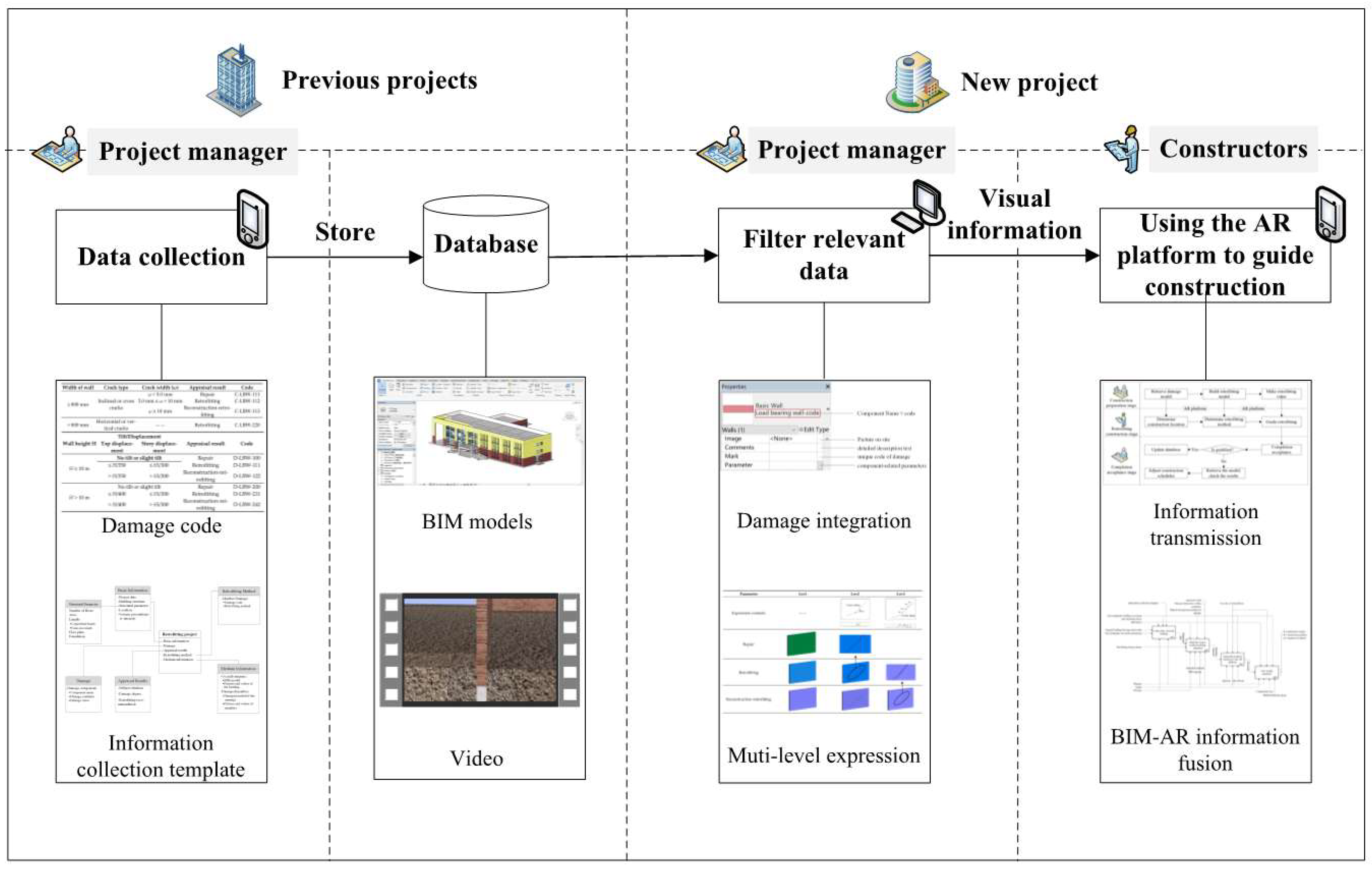
This study proposes combining BIM and AR application methods to address the problem of retrofitting crews being unable to complete engineering tasks owing to insufficient experience, and to realize the visualization of relevant methods and technologies in the retrofitting process. This approach consists of three stages: data collection, information reuse, and construction guidance [54]. The framework is shown in Figure 1.
To ensure the comprehensiveness of the building-related data in the data collection stage, this study designed a relatively comprehensive information collection template for project managers, to facilitate the retrieval of information by relevant personnel in the subsequent reuse phase. The template provides basic project information such as the project start date, building type, and location, as well as the specific methods used in the construction project; moreover, it includes building images, BIM models, and simulation animations.
During the information reuse phase, it should be ensured that users can easily search and retrieve relative defect data from the stored information. For that purpose, an encoding system of retrofitting method is developed, which is explained in detail in Section 5.1. This would assist the user not only to understand whole retrofitting knowledge but also to search and retrieve the needed information without any detailed damage knowledge. The reused data mainly concern the component models and construction methods. If the same encoding as the new project cannot be retrieved from the database, it is necessary to rebuild the BIM model and generate new construction animations.
During the construction guidance stage, the matched information is used to guide the activities of the construction crew. A construction process incorporates many procedures and complicated methods, and construction tasks often cannot be completed with quality and quantity. These situations can be avoided to a great extent if construction workers have ready access to damage information and building models. AR combines virtual objects with the real world. Using an AR platform can expand the application of BIM models in construction and provides guidance ideas for construction workers on-site.
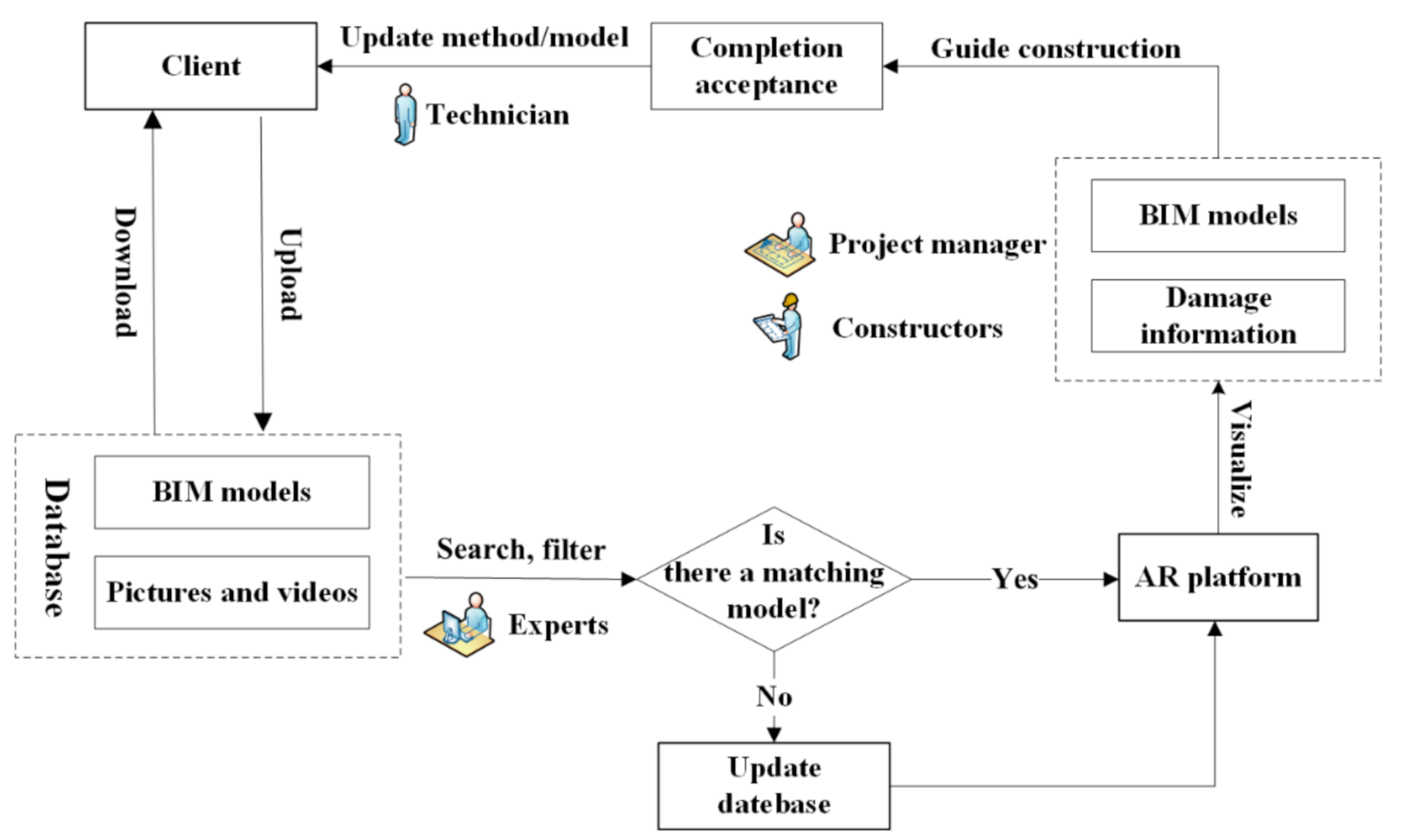
To better apply the above methods to damaged buildings, a more detailed description of the application of BIM and AR in the repair and retrofitting of damaged buildings following new earthquakes is provided, as shown in Figure 2. Information regarding the processes of reinforcing previous post-earthquake buildings is stored in the database through collection templates. Experts preparing new projects can search for and filter relevant building information in the database. If there are projects or members that match well, the searched information is used for AR-based retrofitting work; if none of the identified buildings match well, the BIM model must be rebuilt for the building. Using the AR platform, the project manager can view a 3D model of the building at any time, to better command and dispatch on-site crews and materials. The builders can view the damage information and retrofitting methods according to the assigned tasks, so as to better complete the construction tasks. After the builder completes the assigned tasks, the inspector performs a quality check (and, if appropriate, indicates acceptance of the work), and transmits an image of the finished work to a technician via mobile feedback.
4. BIM-Based Data Collection
The application of BIM and AR in the post-earthquake retrofitting of buildings expands the scope of BIM models using AR and extends the amount of time required. Therefore, before studying the application of BIM and AR, it is necessary to study the required models and information, and to explore the methods and approaches for the continuous use of BIM damage models, BIM retrofitting models, and AR virtual scene models, so as to lay a foundation for the BIM and AR-based retrofitting application research. This section describes the construction of BIM-based seismic models, and the collection of information.
4.1. Construction of Seismic Damage Model
The difference between a seismic building model and a general building model lies in the treatment of damaged components, such as cracks in the walls, deformations of windows and doors, and the spalling of concrete. This information plays a vital role in subsequent construction, so the treatment of these special components is crucial to the accuracy of the retrofitting model.
The seismic damage model is constructed based on post-earthquake pictures taken at the site, post-earthquake building appraisal reports, and retrofitting design drawings. When building the model, it is necessary to use BIM software to draw the model. Revit is a mainstream BIM software used in major projects, and provides many functions and easy operation. As such, this study utilizes Revit to draw the models.
First, a non-damage model is built in Revit by drawing the walls, columns, floors, and other components; then, the damage is represented in the non-damage model. Theoretically, all damage should be represented in the model, but the repair and retrofitting measures can vary depending on the degree of damage to the component. Therefore, the representation requirements for the model can be different. Accordingly, a multi-level expression method is used to solve this problem. The multi-level method can retain and present damage information in the context of the retrofitting requirements for different components. Regarding the relevant code [55] and appraisal results, the components are classified into three levels: repair, retrofitting, and reconstruction-retrofitting, based on the final retrofitting design. Refer to the above standards, standards of multiple levels of detail (multi-LoD) parametric model [56], and multi-LoD BIM models for Wooden architectural heritage (WAH) components [57], we propose the multi-level expression method for the damage and define three accuracy levels: Lev1, Lev2, and Lev3. The objects applicable to the model correspond to these three levels.
Technical specification for post-earthquake urgent assessment and repair of buildings stipulates that for load-bearing walls with a width greater than 800 mm, when a crack width ω < 5.0 mm, the crack must be repaired; when 5.0 mm ≤ ω < 10 mm, the crack should be retrofitted; when ω ≥ 10 mm, the area should be partially demolished and rebuilt before retrofitting. The following uses the load-bearing wall crack as an example to introduce the construction of the multi-level model and expression of the information in detail, as shown in Table 1.
- Lev1 is mainly suitable for components that do not need to be repaired, or that can be simply processed. This type of crack generally does not affect the normal use of the wall, so the amount of damage can be unclear. BIM engineers only need to mark the damaged components in the model with color blocks, e.g., using green, blue, and purple to indicate repair, retrofitting, and rebuild/retrofitting.
- Lev2 is used for retrofitting needs. The length, depth, width, and development shape of the crack must be clarified for the retrofitting construction. In the model, a prism is used to reflect the length, maximum depth, and width of the crack; in addition, the outline of the crack is reflected, such as “wide in the middle, narrow at both ends”, or “wide at the top and narrow at the bottom”.
- Lev3 provides more detailed information for the construction of severely damaged components. This type of component must be partially demolished, rebuilt, and retrofitted. The development pattern of the crack needs to be depicted in the model. In addition to the maximum depth and width information contained in Lev2, the changes in depth and width need to be described to provide more comprehensive damage information for the retrofitting design.
4.2. Information Collection Templates
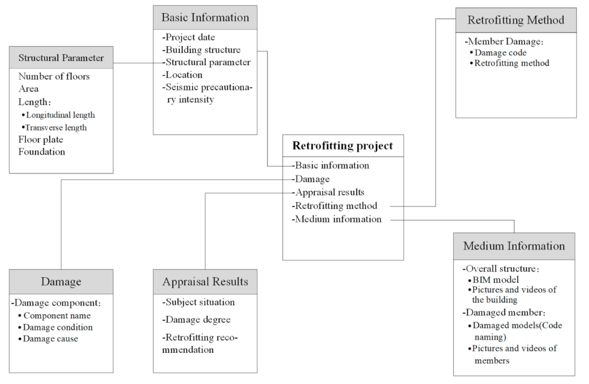
To ensure the quality of the information on the post-earthquake buildings, this study designs a relatively comprehensive information collection template. This template integrates and stores the BIM model, using the method proposed in Section 4.1. It collects basic information (and damage information) pertaining to buildings, for project crews to view. It also provides reference methods and models for other projects, to facilitate searching and reading. This template includes basic information concerning the project, descriptions of the damaged members, appraisal and analysis results, and retrofitting methods, as well as pictures, videos, original design drawings, and BIM models of the building. The information collection elements are shown in Figure 3. A five-story masonry house damaged after the Wenchuan earthquake in Sichuan is taken as an example to explain the information in the template, as shown in Table 2.
The content of the template includes five categories, as follows.
- “Basic Information” includes the date of the project, building structure, structural parameters, area, and seismic intensity. The structural parameters include, but are not limited to, the number of floors, area, length, type of floor plate, and foundation of the building.
- “Damage” consists of “Component Name”, “Damage Condition”, and “Damage Cause”; a detailed inspection of a post-earthquake building is conducted to confirm whether the site structural layouts and dimensions of the beams and columns are consistent with the original drawings and designs. It is necessary to check, e.g., whether the floor slab has fallen or broken the precast slabs; whether the walls of each layer are damaged; whether there are cracks in the buttress and/or zones under the windows of each floor; and whether the foundation is in a stable state. The “Component Name” specifies each damaged component; the “Damage Condition” is a detailed description of the damaged part, including cracks, deformation, and fractures; and the “Cause of Damage” describes the factors leading to the damage. For example, the “Component Name” of the wall could be a load-bearing wall, the “Damage Condition” could be a cross-crack with two sharp ends and a wide middle that tends to develop toward both ends, and the “Cause of Damage” could be the main tensile stress. If the damaged member cannot be further detailed, the “Component Name” can be omitted.
- “Appraisal Results” indicates the degree of the damage and corresponding retrofitting recommendations, as combined with the post-earthquake damage of the building and relevant standards. There are five damage degrees: basic integrity, minor damage, moderate damage, severe damage, and partial or total collapse. Based on the code, moderately damaged buildings, severely damaged buildings with restoration value, and ancient buildings with partial collapses of non-main structures are given “Retrofitting Recommendations”, and can be used safely after retrofitting.
- “Retrofitting Method” is based on results of the appraisal and damage and is used to guide the retrofitting of each damaged member. Different types of damage correspond to different retrofitting methods. For each type of damage, the required information includes the “Damage Code” and “Retrofitting Method”. For the same kind of damage, the corresponding “Retrofitting Method” in the table should be used at the same time. The “Damage Code” strictly follows the guidelines given in Section 5.1.
- “Medium Information” includes images, videos, and original construction drawings, along with the BIM model of the building.
5. Code-Based Information Reuse
In the information reuse stage, the search and screening of BIM models is the key. In order to shorten the data screening time, an information coding method is proposed. The relevant personnel could retrieve the desired result through the key digits of the component code. The main types of damage in a post-earthquake structure are cracks and deformation; therefore, the following section introduces the information encoding method, with these two types of damage described as examples.
5.1. Encoding System
5.1.1. Code of Crack
Cracks can be divided into wall cracks and structural cracks. Wall cracks include buttress cracks, cracks in the upper and lower parts of a hole, and cracks in the corners of the hole. In the case of cracks in a load-bearing wall, for example, different wall widths, shapes, and widths correspond to different degrees of damage, as shown in Table 3. For the different cracks, a new coding criterion is defined based on the Omniclass classification, to classify them by number. The first digit of the code designates the type of damage as indicated by the initial letter, such as C for “crack” or D for “deformation”. The first and second digits are connected with a hyphen “-” to facilitate users understanding the definition of the code, and to prevent confusion between the first and second digits. The second digit designates the damaged component using an acronym, e.g., LBW stands for “load bearing wall” and CW stands for “cross wall”. The second and third digits are connected by another hyphen “-”; the code after the hyphen is expressed using Arabic numerals. The third digit designates the width of the wall, i.e., 1 for “wall width ≥ 800 mm” and 2 for “wall width < 800 mm”. The fourth digit designates the type of crack, i.e., 1 for “inclined or cross cracks” and 2 for “horizontal or vertical cracks”. The fifth digit designates the width of the crack ω, i.e., 1 for “ω < 5.0 mm”, 2 for “5.0 mm ≤ ω < 10 mm”, and 3 for “ω ≥ 10 mm”. For a damaged component, if one or more digits of the code after the second hyphen do not need to be expressed, 0 can be used as a placeholder. For example, C-LBW-220 indicates “horizontal or vertical cracks in load-bearing walls less than 800-mm wide”. For other damage to components outside the cracks of the load-bearing wall, the codes before the hyphen must conform to the above definition. If there is a concept not defined above, it is possible to add a new code to the existing code after the hyphen, and to use numbers from 1 to 9 to define its coding rules under the premise(s) of the existing standards.
5.1.2. Code of Deformation
The deformation of components in earthquake-damaged buildings is mainly reflected in the tilt or displacement of columns and walls. This section mainly considers the deformation of load-bearing walls as an example and introduces the coding system based on the coding rules proposed above. The first digit of the code designates “deformation” with a capital D. The second digit designates the “load-bearing wall” with LBW, the same as above. The specific code definitions of the numbers after the second hyphen are shown in Table 4.
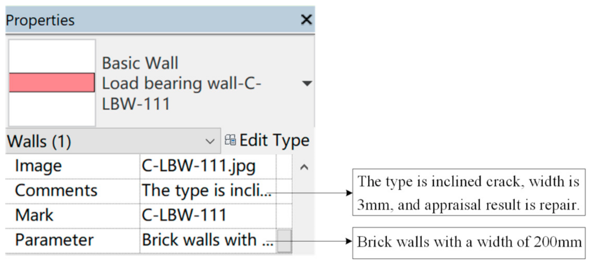
5.2. Information Storage
The BIM model and other media data regarding the individual damaged components should be named after the code as files and stored in the database. This facilitates the subsequent retrieval of the construction process and provides a basis for finding the same type of project. In addition to the code, other information of the damaged component models should be integrated and managed, so that it can be easily viewed by the relevant crews. In Revit, each component model is associated with a properties tab, which allows crews to manage the details of the component in an electronic list. This study arranges the content of the information that needs to be integrated based on the needs of the post-earthquake retrofitting of buildings, including a unique code for the damage; a detailed text description of the damage; and component-related parameters, are shown in Figure 4.
6. AR-Based Construction Guidance
The application of BIM and AR in the post-earthquake retrofitting of buildings is reflected in the use of AR to visualize the BIM model for damage identification, method design, retrofitting construction, and completion inspection. AR makes the visualization process more convenient. According to the functional requirements for different stages, the corresponding models are retrieved from the BIM model built above. The appropriate AR device is selected to realize full-cycle visualization of the BIM models. The following section introduces the information transmission process in the AR environment, along with the integration process for the BIM model and AR.
6.1. Information Transfer in AR
The application of the BIM-AR system in the post-earthquake retrofitting of buildings is mainly reflected as follows. First, an AR viewport is used to view a model of the damaged member; this provides a basis for determining the retrofitting solution, and for building the retrofitting model and animation. Second, during the retrofitting construction, an AR mobile device is used to superimpose the retrofitting model on the actual component, to thereby provide retrofitting guidance to the construction crews. Third, when problems such as substandard construction quality or reworking are found during project completion and acceptance, the AR platform can be used to compare the actual components with the model, e.g., to identify and correct problems on time.
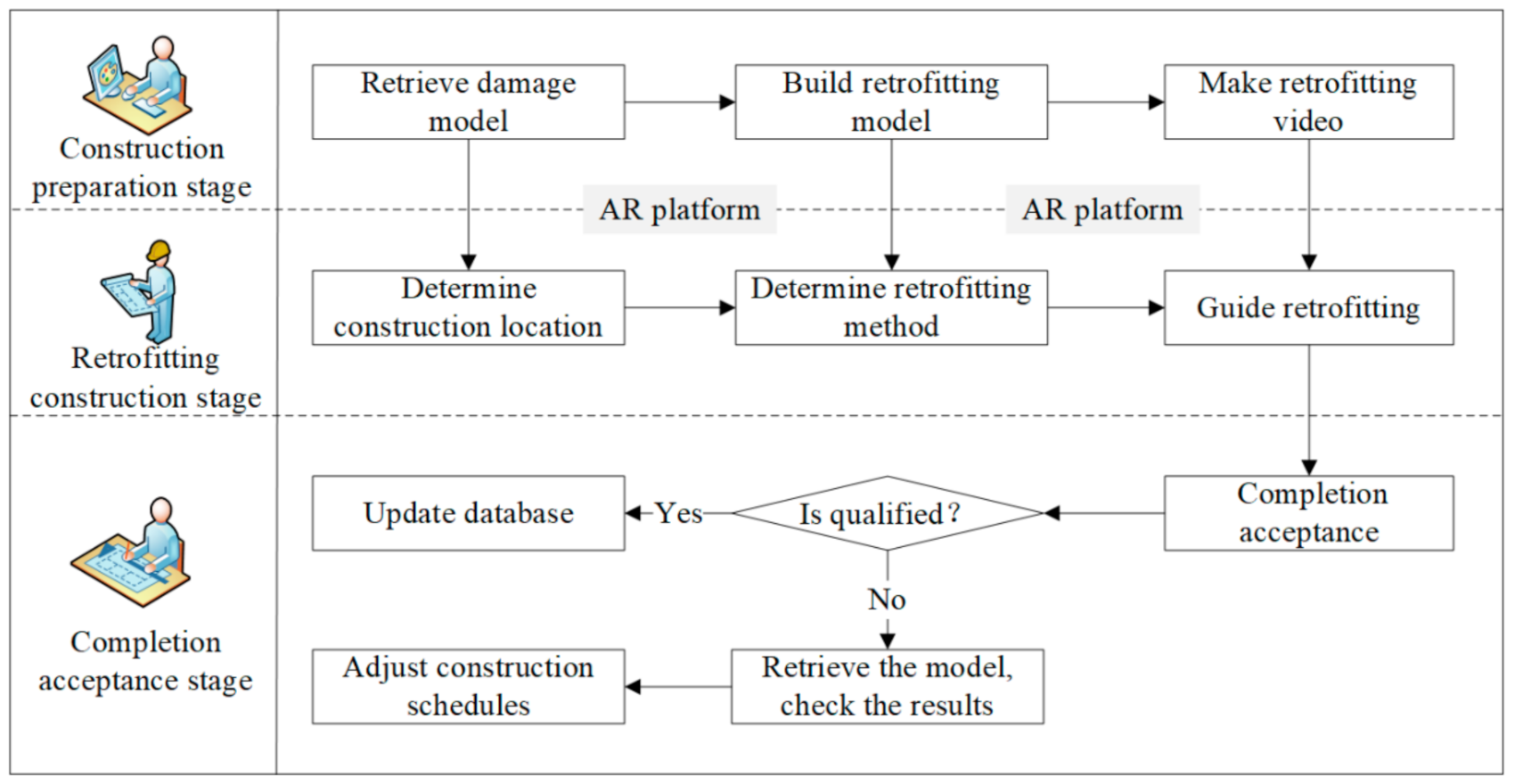
In view of the application scenario for the BIM model, the transmission process for related information in the AR environment is shown in Figure 5. The information transmission in the retrofitting process can be roughly divided into three aspects, as described below.
- Construction preparation stage. The damage model of the building is retrieved from the model base and uploaded to the AR system. All designers can use the AR platform to view the client building to enable remote design guidance and collaboration, as well as to propose recommendations and methods for retrofitting. According to the design requirements, retrofitting models and animations are built, integrated, and stored in the BIM database. Then, all of the information needed during construction is uploaded to the AR platform for easy viewing.
- Retrofitting construction stage. The construction site is divided into several zones, based on appraisal recommendations and the retrofitting design. Each area of the model is installed with an AR reference tracker placed at the appropriate location, so as to facilitate model matching and spatial positioning on the site. Contractors can scan a reference tracker through a handheld mobile device to retrieve the model of the corresponding retrofitted area and can superimpose and compare the physical component and virtual model. This can help the contractor quickly determine the location for the retrofitting. The AR visualization of the model provides on-site views of retrofitting methods for the relevant personnel and can be used by managers to allocate crews and improve construction efficiency. Construction crews can view retrofitting videos and learn by scanning markers arranged in advance, enabling real-time construction guidance.
- Completion acceptance stage. At the end of the construction phase, the inspectors must check the quality of the project. If the project quality deviates from the planned value, the crews mark a screenshot of the problem interface, and send it back to the system to provide a reference for the management staff (e.g., to analyze and make decisions in the next step). By retrieving the original model and comparing it with the feedback, the technicians can adjust the construction plan, and the construction crews can further strengthen and maintain the building according to their assigned tasks. Once the project has been completed and accepted, the information in the database can be updated. The technical design and construction tasks for the next stage are arranged in the system, and the above process is repeated.
6.2. Information Fusion of BIM and AR
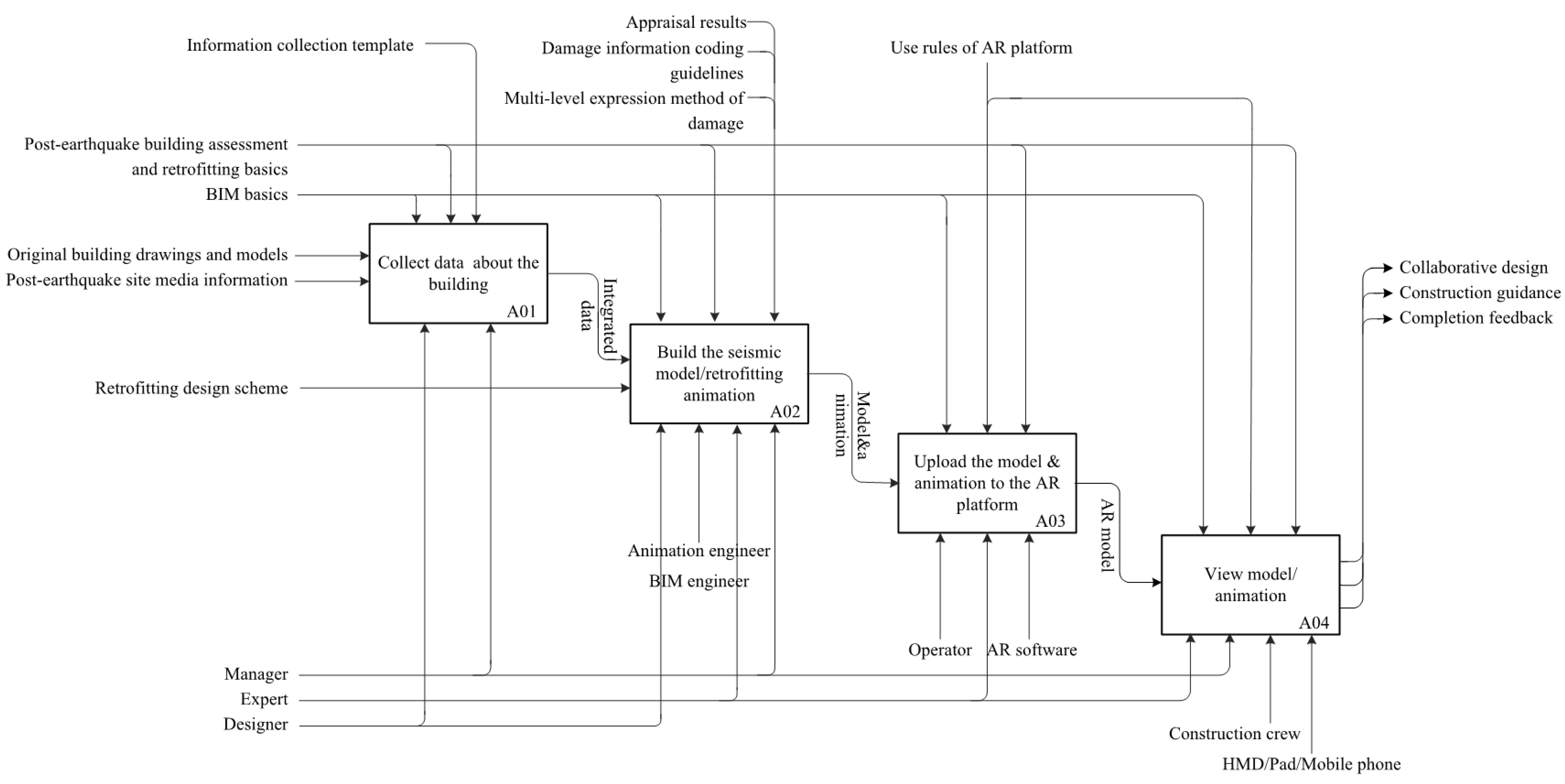
“Integration Definition for Function Modeling” (IDEF0) is a method for graphically representing the specific steps, operations, data elements, and connections between the various activities required to complete a task [58]. IDEF0 models comprise of boxes and arrows. A box represents a system function, and an arrow represents the information required by the box. This information is composed of four parts: input, output, control, and mechanism. The process of integrating BIM and AR information is illustrated using IDEF0 [33], as shown in Figure 6. It encompasses four main activities: collect data about the building (Node A01), build the seismic model/retrofitting animation (Node A02), upload the model and animation to the AR platform (Node A03), and view the model/animation (Node A04).
As shown in Figure 6, the inputs are the “original building drawings and models” and “post-earthquake site media information”, and the final outputs are the AR model usage scenarios for the different retrofitting stages. The implementation of the four functions above is controlled by “BIM basics” and “Post-earthquake building assessment and restoration basics”, and the “Manager”, "Expert”, and “Designer” are employed as the mechanisms for driving the implementation of each function. The “Manager” participates in all activities as the scheduling manager of the project.
The function “Collect data about the building” operates based on the input information. During this period, building-related information is collected according to the “Information collection template” proposed above, and “Integrated data” is output. This output will also be used as input for subsequent functions. The above activities should be performed in cooperation with the “Designer”.
The function “Build the seismic model/retrofitting animation” has “Retrofitting design scheme” and “Integrated data” as its inputs. The output is “Model and animation”. To achieve this function, the “Designer”, “Animation engineer”, and “BIM engineer” must work together to process the model in accordance with the “Damage information coding guidelines” and “Multi-level expression method of damage”, and must follow the constraints imposed by the “Appraisal results”.
The input of the function “Upload the model and animation to the AR platform” is the output “Model and animation” from A02. This function needs to be performed not only by an “Operator”, but also by using “AR software” and strictly following the “Use rules of AR platform”. The output of this function is the “AR model”; it can be used by different types of AR devices and applications and provides input information for the implementation of subsequent functions.
The function “View model/animation” takes “AR model” as an input to perform its activities. It can be used for appraisal of seismic damage, analysis of an overall design, guidance for construction crews, and assistance in completion and acceptance. For different work purposes, each participant selects the appropriate device, and follows the “Use rules of AR platform” to output the AR model scenarios for the function. For example, retrofitting personnel who need to perform “Construction guidance”, i.e., “Construction crews”, should use “Mobile phone” to view models and animations under the guidance of the “Use rules of AR platform”.
6.3. BIM-AR Based Visualization Testing
The post-earthquake retrofitting visualization of buildings described above has two major functions: viewing the BIM model, and simulating an animation of the retrofitting using mobile devices. A wall damaged by shear was taken as an example for testing these functions.
According to the method proposed in Section 5.2, Augin® is chosen as the AR platform. It can operate on mobile device, web pages, and plug-in software. The mobile device for the AR application can be a tablet or a smartphone. The application system of the smartphone can be Android or Apple, but all the above devices need to be after 2017. In general, the more memory space the device has, the smoother the operation will be. Tablets have a greater advantage in terms of model loading speed, but they are larger and less portable. Smartphones are slow to load, but easy to get and easy to carry. Smartphones are chosen as the display tool to facilitate construction. This study uses the iPhone 8 as the mobile device for the AR application.
The experimental steps are as follows.
Construction preparation phase. Building information models and retrofitting videos are obtained and uploaded to the AR platform. Managers assign AR application accounts to construction workers and upload models and videos according to different construction areas. Workers in the same area have the same account and can see the same model. Managers upload models and videos on the plug-in software and/or web page, as shown in Figure 7A–D. To view the model on a real scale, this study uses a reference tracker to achieve fast localization of the AR model in the real world. In particular, a virtual tracking mark is placed in the model, as shown in Figure 7F. At the same time, the managers place physical trackers in advance at the corresponding locations on the construction site, and the placement locations are different for different construction areas. In addition, they upload the retrofitting video and the corresponding thumbnails on the web side. The thumbnails are printed and placed at the location where the retrofitting is needed.
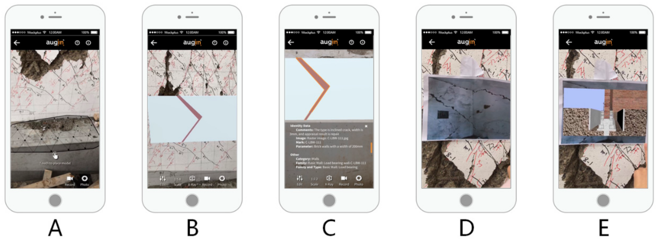
Retrofitting construction phase. Once the preparation is complete, the model and video are synchronized to the AR application on the mobile device. After scanning the pre-arranged reference tracker on the AR interface, the model appears in the corresponding position and can be viewed at a ratio of 1:1, as shown in Figure 8. After specifying the construction location based on the overall model, the crews use the iPhone 8 to view the BIM model of the local component. The integrated BIM damage information described in Section 4.1 is presented by clicking on the component, as shown in Figure 9A–C. At any stage of construction, a video of the retrofitting can be viewed. The video is played by scanning the thumbnail in the AR interface, as shown in Figure 9D,E. Workers can watch the video in an AR environment to guide the retrofitting construction.
7. Discussion
The results showed that the main weaknesses of the current retrofitting (namely: poor management, poor intuitiveness, and weak coordination) can be overcome. This approach improves the intuitiveness, convenience, collaboration, and intelligence of construction, providing new ideas for rapid retrofitting. The case study allowed identification of benefits in adopting the proposed framework. Figure 10 shows the possible outcomes of the proposed framework. Using the BIM model and AR visualization software, users can quickly determine the construction location, and learn while working on the site replacing the traditional training process. This reduces the repetition rate and also improves the efficiency and quality of task. Users can also view the detailed information of components anytime and anywhere, which reduces paperwork, avoids unnecessary waste, saves costs, and improves decision making.
During the experiments, there are cases where the model takes a long time to load or even fails to load, which the authors believe is related to the memory of the mobile device and the size of the model. The above situation usually occurs when viewing the overall model, and when loading a single model such as a wall, there is no failure to load. Replacing a smartphone with a tablet makes the model load significantly faster.
Although it is convenient to use a smartphone as an AR device, there are some shortcomings when using one to guide construction. Builders have to hold the device with one hand to view the model and cannot free their hands; this may cause inconvenience in retrofitting construction.
Another shortcoming of the proposed framework is security issues: working with mobile AR applications may cause users to lose focus on the surrounding area, which can be very dangerous on construction sites and lead to safety issues [59]. So, for safety reasons, workers need to be trained to use the system properly.
8. Conclusions and Future Work
This study presents a visualization method and framework for the application of BIM and AR in the post-earthquake retrofitting of buildings. Exploiting advantages and help from the potentials of BIM and AR and their integration, a system has been developed for integrating multi-dimensional information, guiding the retrofitting construction, and facilitating collaboration among builders. The visualization process is tested through experiments, which demonstrate the feasibility of the method.
The results confirm that objectives of improving the intuitiveness and convenience of retrofitting can be pursued through the proposed retrofitting visualization method. The multi-level expression method and damage codes integrate the damage into the BIM model to improve the integration of information. The information collection template identifies the information required for retrofitting projects, providing a reference for similar projects.
In the framework of the experimental approach followed by the proposed methodological examination, the difficulties encountered during the testing phase can also be considered as positive results and as seeds for further consideration and research work.
Regarding possible future developments to optimize the proposed approach for integrating BIM and AR for retrofitting visualization purposes, a more convenient mobile device for the AR application such as Hololens would improve the experience, freeing the hands of construction workers and providing more detailed procedures to guide construction.
Author Contributions
Conceptualization, Z.L. and W.B.; methodology, Z.L. and W.B.; software, W.B.; validation, Z.L. and W.B.; formal analysis, Z.L.; investigation, Z.L.; resources, Z.L.; data curation, W.B.; writing—original draft preparation, W.B.; writing—review and editing, W.B.; funding acquisition, Z.L. All authors have read and agreed to the published version of the manuscript.
Funding
This research was funded by the National Key R&D Program of China, grant number 2019YFC1509304-06.
Institutional Review Board Statement
Not applicable.
Informed Consent Statement
Not applicable.
Data Availability Statement
Data sharing not applicable.
Acknowledgments
The authors would like to thank Beijing University of Technology, Beijing, China, for their support throughout the research project.
Conflicts of Interest
The authors declare no conflict of interest.
References
- The Human Cost of Disasters: An Overview of the Last 20 Years (2000–2019). Available online: http://dds.cepal.org/redesoc/publication?id=5361 (accessed on 18 January 2021).
- Akhlaghi, M.M.; Bose, S.; Mohammadi, M.E.; Moaveni, B.; Stavridis, A.; Wood, R.L. Post-earthquake damage identification of an RC school building in Nepal using ambient vibration and point cloud data. Eng. Struct. 2021, 227, 111–413. [Google Scholar] [CrossRef]
- Liang, G. Study on Simulation of Damage after Earthquake and Reinforcement of Masonry Wall Based on Finite Element Method. Master’s Thesis, Institute of Engineering Mechanics, China Earthquake Administration, Harbin, China, 2017. [Google Scholar]
- Zhai, W. The Application of BIM Technique in Resistance Building Reinforcement Construction. Master’s Thesis, Southwest University of Science and Technology, Chengdu, China, 2019. [Google Scholar]
- Chalhoub, J.; Ayer, S.K. Using mixed reality for electrical construction design communication. Autom. Constr. 2018, 86, 1–10. [Google Scholar] [CrossRef]
- Liu, Z.; Zhang, A.; Wang, W.; Wang, J. Dynamic Fire Evacuation Guidance Method for Winter Olympic Venues Based on Digital Twin-Driven Model. J. Tongji Univ. 2020, 48, 962–971. [Google Scholar]
- Jiang, H.; Zhao, X.; Zhang, B. Seismic design and BIM application on an assembly building in design-construction integration. Earthq. Resist. Eng. Retrofit. 2019, 41, 119–128. [Google Scholar] [CrossRef]
- Hamledari, H.; Azar, E.R.; Mccabe, B. IFC-based development of as-built and as-is BIMs using construction and facility inspection data: Site-to BIM data transfer automation. J. Comput. Civ. Eng. 2018, 32, 04017075. [Google Scholar] [CrossRef]
- Lu, Q.; Lee, S. Image-based technologies for constructing as-is building information models for existing buildings. J. Comput. Civ. Eng. 2017, 31, 04017005. [Google Scholar] [CrossRef]
- Zhang, H. Application of Renovation in Existing Buildings with BIM Technology. Master’s Thesis, Southwest Jiaotong University, Chengdu, China, 2016. [Google Scholar]
- Ghobadi, M.S.; Jazany, R.A.; Farshchi, H. In situ repair technique of infill masonry walls in steel frames damaged after an earthquake. Eng. Struct. 2019, 178, 665–679. [Google Scholar] [CrossRef]
- Kassem, N.; Atta, A.; Etman, E. Structural behavior of strengthening masonry in-filled frames subjected to lateral load using bonded and un-bonded CFRP. KSCE J. Civ. Eng. 2017, 21, 818–828. [Google Scholar] [CrossRef]
- Baloević, G.; Radnić, J.; Grgić, N.; Matešan, D. Shake-table study of plaster effects on the behavior of masonry-infilled steel frames. Steel Compos. Struct. 2017, 23, 195–204. [Google Scholar] [CrossRef]
- Messali, F.; Metelli, G.; Plizzari, G. Experimental results on the retrofitting of hollow brick masonry walls with reinforced high performance mortar coatings. Constr. Build. Mater. 2017, 141, 619–630. [Google Scholar] [CrossRef]
- Spence, R. Earthquake loss estimation for reinforcetd concrete buildings: Some problems. Mag. Concr. Res. 2008, 60, 701–707. [Google Scholar] [CrossRef]
- Ma, L.; Sacks, R.; Zeibak-Shini, R. Information modeling of earthquake-damaged reinforced concrete structures. Adv. Eng. Inform. 2015, 29, 396–407. [Google Scholar] [CrossRef]
- Zhang, Y.; Liu, T. Energy Dissipation Design for the Concrete Structures in a Stadium in Post-earthquake Restoration and Reconstruction. China Earthq. Eng. J. 2019, 41, 16–22. [Google Scholar] [CrossRef]
- Vlachakis, G.; Vlachaki, E.; Lourenco, P.B. Learning from failure: Damage and failure of masonry structures, after the 2017 Lesvos earthquake (Greece). Eng. Fail. Anal. 2020, 117, 22. [Google Scholar] [CrossRef]
- Anil, E.B.; Akinci, B.; Garrett, J.H.; Kurc, O. Information requirements for earthquake damage assessment of structural walls. Adv. Eng. Inform. 2016, 30, 54–64. [Google Scholar] [CrossRef]
- Viskovic, A.; Zuccarino, L.; Kwiecień, A.; Zając, B.; Gams, M. Quick Seismic Protection of Weak Masonry Infilling in Filled Framed Structures Using Flexible Joints. Key Eng. Mater. 2017, 747, 628–637. [Google Scholar] [CrossRef]
- Jia, Y. A Study on Restoration and Reconstruction of Stricken Areas by Earthquakes—A Case Analysis of Rural Regions. Master’s Thesis, Institute of Geology, China Earthquake Administration, Harbin, China, 2006. [Google Scholar]
- Akcay, C.; Bozkurt, T.S.; Sayin, B.; Yildizlar, B. Seismic retrofitting of the historical masonry structures using numerical approach. Constr. Build Mater. 2016, 113, 752–763. [Google Scholar] [CrossRef]
- Doukari, O.; Naudet, B.; Teulier, R. Merging IFC-Based BIM Models: A New Paradigm and Co-Design Support Tool. Int. J. 3-D Inf. Model. 2017, 6, 51–64. [Google Scholar] [CrossRef] [Green Version]
- ISO. ISO 29481-1: 2016 Building Information Models—Information Delivery Manual—Part 1: Methodology and Format; International Organization for Standardization: Geneva, Switzerland, 2016; Available online: https://www.iso.org/standard/60553.html (accessed on 23 December 2019).
- Zhao, L.; Liu, Z.; Mbachu, J. An Integrated BIM–GIS Method for Planning of Water Distribution System. ISPRS Int. J. Geo-Inf. 2019, 8, 331. [Google Scholar] [CrossRef] [Green Version]
- Zheng, M.; Xue, Q.; Wei, W.; Xu, Z. A Review on the Research Using Building Information Model Technology in Multi-Hazards Topic. J. Graph. 2018, 39, 829–834. [Google Scholar]
- Vitiello, U.; Ciotta, V.; Salzano, A.; Asprone, D.; Manfredi, G.; Cosenza, E. BIM-based approach for the cost-optimization of seismic retrofit strategies on existing buildings. Autom. Constr. 2019, 98, 90–101. [Google Scholar] [CrossRef]
- Xu, Z.; Lu, X.; Zeng, X.; Xu, Y.; Li, Y. Seismic loss assessment for buildings with various-LOD BIM data. Adv. Eng. Inform. 2019, 39, 112–126. [Google Scholar] [CrossRef]
- Zhen, X.; Furong, Z.; Wei, J.; Yingying, W.; Mingzhu, Q.; Yajun, Y. A 5D simulation method on post-earthquake repair process of buildings based on BIM. Earthq. Eng. Eng. Vib. 2020, 19, 541–560. [Google Scholar] [CrossRef]
- Sun, C.; Jiang, S.; Skibniewski, M.J.; Man, Q.; Shen, L. A literature review of the factors limiting the application of BIM in the construction industry. Technol. Econ. Dev. Econ. 2017, 23, 764–779. [Google Scholar] [CrossRef] [Green Version]
- Alizadehsalehi, S.; Hadavi, A.; Huang, J.C. From BIM to extended reality in AEC industry. Autom. Constr. 2020, 116, 103254. [Google Scholar] [CrossRef]
- Kwon, O.; Park, C.; Lim, C. A defect management system for reinforced concrete work utilizing BIM, image-matching and augmented reality. Autom. Constr. 2014, 46, 74–81. [Google Scholar] [CrossRef]
- Machado, R.L.; Vilela, C. Conceptual Framework for Integrating Bim And Augmented Reality in Construction Management. J. Civ. Eng. Manag. 2020, 26, 83–94. [Google Scholar] [CrossRef]
- Li, X.; Yi, W.; Chi, H.L.; Wang, X.; Chan, A.P. A critical review of virtual and augmented reality (VR/AR) applications in construction safety. Autom. Constr. 2018, 86, 150–162. [Google Scholar] [CrossRef]
- del Amo, I.F.; Erkoyuncu, J.; Vrabič, R.; Frayssinet, R.; Reynel, C.V.; Roy, R. Structured authoring for AR-based communication to enhance efficiency in remote diagnosis for complex equipment. Adv. Eng. Inform. 2020, 45, 101096. [Google Scholar] [CrossRef]
- Azuma, R. Survey of augmented reality. Teleoperators Virtual Environ. 1997, 6, 355385. [Google Scholar] [CrossRef]
- Keil, J.; Edler, D.; Dickmann, F. Preparing the HoloLens for user Studies: An Augmented Reality Interface for the Spatial Adjustment of Holographic Objects in 3D Indoor Environments. KN J. Cartogr. Geogr. Inf. 2019, 69, 205–215. [Google Scholar] [CrossRef] [Green Version]
- Kopsida, M.; Brilakis, I. Real-Time Volume-to-Plane Comparison for Mixed Reality–Based Progress Monitoring. J. Comput. Civ. Eng. 2020, 34, 04020016. [Google Scholar] [CrossRef]
- Delgado, J.M.D.; Oyedele, L.; Demian, P.; Beach, T. A research agenda for augmented and virtual reality in architecture, engineering and construction. Adv. Eng. Inform. 2020, 45, 101122. [Google Scholar] [CrossRef]
- Dong, S. Scalable and Extensible Augmented Reality with Applications in Civil Infrastructure Systems. Ph.D. Thesis, Department of Civil and Environmental Engineering, University of Michigan, Ann Arbor, MI, USA, 2012. [Google Scholar]
- Kamat, V.R.; El-Tawil, S. Evaluation of augmented reality for rapid assessment of earthquake-induced building damage. J. Comput. Civ. Eng. 2007, 21, 303–310. [Google Scholar] [CrossRef]
- Matini, M.R.; Andaroodi, E.; Ono, K. A 3D approach to reconstitution of the adobe citadel of Bam after earthquake: A complementary interpretation of architectural heritage knowledge, aerial photogrammetry, and heterogeneous data. Int. J. Archit. Herit. 2019, 13, 600–618. [Google Scholar] [CrossRef]
- Dai, F.; Dong, S.; Kamat, V.R.; Lu, M. Photogrammetry Assisted Measurement of Interstory Drift for Rapid Post-disaster Building Damage Reconnaissance. J. Nondestruct. Eval. 2011, 30, 201. [Google Scholar] [CrossRef]
- Kim, W.; Kerle, N.; Gerke, M. Mobile augmented reality in support of building damage and safety assessment. Nat. Hazards Earth Syst. Sci. 2016, 16, 287–298. [Google Scholar] [CrossRef] [Green Version]
- Mirshokraei, M.; De Gaetani, C.I.; Migliaccio, F. A Web-Based BIM–AR Quality Management System for Structural Elements. Appl. Sci. 2019, 9, 3984. [Google Scholar] [CrossRef] [Green Version]
- Wang, J.; Wang, X.; Shou, W.; Xu, B. Integrating BIM and augmented reality for interactive architectural visualisation. Constr. Innov. 2014, 14, 453–476. [Google Scholar] [CrossRef]
- Lee, J.G.; Seo, J.; Abbas, A.; Choi, M. End-Users’ Augmented Reality Utilization for Architectural Design Review. Appl. Sci. 2020, 10, 5363. [Google Scholar] [CrossRef]
- Zaher, M.; Greenwood, D.; Marzouk, M. Mobile augmented reality applications for construction projects. Constr. Innov. 2018, 18, 152–166. [Google Scholar] [CrossRef] [Green Version]
- Wang, X.; Love, P.; Kim, M.J.; Park, C.-S.; Sing, C.-P.; Hou, L. A conceptual framework for integrating building information modeling with augmented reality. Autom. Constr. 2013, 34, 37–44. [Google Scholar] [CrossRef]
- Chu, M.; Matthews, J.; Love, P.E.D. Integrating mobile Building Information Modelling and Augmented Reality systems: An experimental study. Autom. Constr. 2018, 85, 305–316. [Google Scholar] [CrossRef]
- Williams, G.; Gheisari, M.; Chen, P.-J.; Irizarry, J. BIM2MAR: An Efficient BIM Translation to Mobile Augmented Reality Applications. J. Manag. Eng. 2015, 31, A4014009. [Google Scholar] [CrossRef]
- Wang, T.-K.; Piao, Y. Development of BIM-AR-Based Facility Risk Assessment and Maintenance System. J. Perform. Constr. Facil. 2019, 33, 04019068. [Google Scholar] [CrossRef]
- Diao, P.-H.; Shih, N.-J. BIM-Based AR Maintenance System (BARMS) as an Intelligent Instruction Platform for Complex Plumbing Facilities. Appl. Sci. 2019, 9, 1592. [Google Scholar] [CrossRef] [Green Version]
- Hou, L.; Chi, H.-L.; Tarng, W.; Chai, J.; Panuwatwanich, K.; Wang, X. A framework of innovative learning for skill development in complex operational tasks. Autom. Constr. 2017, 83, 29–40. [Google Scholar] [CrossRef]
- JGJT415-2017 Technical Specification for Post-Earthquake Urgent Assessment and Repair of Buildings. Available online: https://www.chinesestandard.net/PDF/BOOK.aspx/JGJT415-2017 (accessed on 4 October 2020).
- Leite, F.; Akcamete, A.; Akinci, B.; Atasoy, G.; Kiziltas, S. Analysis of modeling effortand impact of different levels of detail in building information models. Autom. Constr. 2011, 20, 601–609. [Google Scholar] [CrossRef]
- Liu, H.; Xie, L.; Shi, L.; Hou, M.; Li, A.; Hu, Y. A method of automatic extraction of parameters of multi-LoD BIM models for typical components in wooden architectural-heritage structures. Adv. Eng. Inform. 2019, 42, 101002. [Google Scholar] [CrossRef]
- Waissi, G.R.; Demir, M.; Humble, J.E.; Lev, B. Automation of strategy using IDEF0—A proof of concept. Oper. Res. Perspect. 2015, 2, 106–113. [Google Scholar] [CrossRef] [Green Version]
- Sabelman, E.; Lam, R. The real-life dangers of augmented reality. IEEE Spectr. 2015, 52, 48–53. [Google Scholar] [CrossRef]
Figure 1.
Building information modeling-augmented reality (BIM-AR)-based construction visualization method framework.
Figure 1.
Building information modeling-augmented reality (BIM-AR)-based construction visualization method framework.

Figure 2.
Visualization process of post-earthquake retrofitting of building.

Figure 3.
Information collection elements.

Figure 4.
Information integration list.

Figure 5.
Information transfer flow in AR.

Figure 6.
BIM-AR information combination flow.

Figure 7.
Uploading data to the AR platform.

Figure 8.
Viewing the model at 1:1 ratio: (A) Project list; (B) AR model; (C) Identify the reference; (D) View the model at 1:1 ratio.
Figure 8.
Viewing the model at 1:1 ratio: (A) Project list; (B) AR model; (C) Identify the reference; (D) View the model at 1:1 ratio.

Figure 9.
Viewing the BIM information and video: (A) Place the model; (B) View the model; (C) View detailed information of damage; (D) Identify the thumbnail; (E) Display the video.
Figure 9.
Viewing the BIM information and video: (A) Place the model; (B) View the model; (C) View detailed information of damage; (D) Identify the thumbnail; (E) Display the video.

Figure 10.
Benefits of the proposed framework.


Table 1.
Schematic diagram of multi-level expression of damage.
| Parameter | Lev1 | Lev2 | Lev3 |
|---|---|---|---|
| Expression contents | —— |  |  |
| Repair |  |  | |
| Retrofitting |  |  |  |
| Reconstruction-retrofitting |  |  |  |
Table 2.
Information collection templates.
| Basic information | ||||
| Date of project | Original construction date | 2010-10 | Retrofitting date | 2020-05 |
| Building structure | Multi-story masonry building | |||
| Structural parameters | Floors | 5 | Area | 2001.56 m2 |
| Length | Longitudinal length is 30 m, transverse length is 12.6 m | |||
| Floorplate | Retrofitted concrete precast hollow slabs | Foundation | Strip foundation | |
| Location | Sichuan, China | |||
| Seismic precautionary intensity | 7 | |||
| Damage | ||||
| Wall | Component name | Load bearing wall, non-load bearing wall | ||
| Damage condition | Cross crack that has two sharp ends and a wide middle and tends to develop toward both ends | |||
| Damage cause | Caused by the main tensile stress | |||
| Longitudinal and cross wall Joint | Component name | Two-and three-story longitudinal and cross wall | ||
| Damage condition | The crack opens along the corner of the wall, wide at the top, and narrow at the bottom | |||
| Damage cause | The whole connection is damaged by the overall bending moment and horizontal shear | |||
| Floorplate | Damage condition | Cracks between plates | ||
| Damage cause | Lack of adequate connection measures between plates | |||
| Structural column ring beam | Damage condition | Spalling of structural columns’ concrete, yielding of steel, and fine cracks in some ring beams | ||
| Damage cause | Low concrete strength during construction | |||
| Appraisal results | ||||
| Subject situation | Stable foundation, cracks in most load-bearing members, some connection damage | |||
| Damage degree | Medium damage level (C) | |||
| Retrofitting recommendations | Requires retrofitting measures before safe use | |||
| Retrofitting methods | ||||
| Wall crack | Damage code | C-LBW-111 | ||
| Retrofitting method | (1) Pressure grouting (Cement latex polymer paste); (2) Retrofitted concrete pin bonding; (3) Double-sided retrofitted mesh troweled cement mortar surface retrofitting | |||
| Damage code | C-LCW-220 | |||
| Retrofitting method | (1) Seismic retrofitting with collapse-resistant design; (2) Pressure grouting (High-strength non-shrinkage grout); (3) Retrofitted concrete pin bonding; (4) Double-sided retrofitted mesh troweled cement mortar surface retrofitting | |||
| Others | Retrofitting method | (1) Strengthen the connection between walls (2) Strengthen the integrity and rigidity of the floor plates and their connection to the walls. (3) Add retrofitted concrete ring beams and structural columns | ||
| Medium information | ||||
| Overall Structure | Building information modeling (BIM) model, pictures, and videos of the building | |||
| Damaged members | Damaged models (code naming), pictures, and videos of members | |||
Table 3.
Coding guidelines for wall cracks in load bearing wall.
| Width of Wall | Crack Type | Crack Width (ω) | Appraisal Result | Code |
|---|---|---|---|---|
| ≥800 mm | Inclined or cross cracks | ω < 5.0 mm | Repair | C-LBW-111 |
| 5.0 mm ≤ ω < 10 mm | Retrofitting | C-LBW-112 | ||
| ω ≥ 10 mm | Reconstruction-retrofitting | C-LBW-113 | ||
| <800 mm | Horizontal or vertical cracks | —— | Retrofitting | C-LBW-220 |
Table 4.
Coding guidelines for deformation in load bearing wall.
| Wall Height H | Tilt/Displacement | Appraisal Result | Code | |
|---|---|---|---|---|
| Top Displacement | Story Displacement | |||
| H ≤ 10 m | No tilt or slight tilt | Repair | D-LBW-100 | |
| ≤H/350 | ≤Hi/300 | Retrofitting | D-LBW-111 | |
| >H/350 | >Hi/300 | Reconstruction-retrofitting | D-LBW-122 | |
| H > 10 m | No tilt or slight tilt | Repair | D-LBW-200 | |
| ≤H/400 | ≤Hi/300 | Retrofitting | D-LBW-231 | |
| >H/400 | >Hi/300 | Reconstruction-retrofitting | D-LBW-242 | |
Note: 1. In the table, H is the height of the apex of the structure, i is the story number, and Hi is the i-th interlayer height. 2. The meanings of the numbers in the code are as follows: (1) For wall height, 1 designates “H ≤ 10 m”, 2 designates “H > 10 m”; (2) 00 designates “no tilt or slight tilt”; (3) For top displacement, 1 designates “≤H/350”, 2 designates “>H/350”, 3 designates “≤H/400”, 4 designates “>H/400”; (4) For story displacement, 1 designates “≤Hi/300”, 2 designates “>Hi/300”.
Publisher’s Note: MDPI stays neutral with regard to jurisdictional claims in published maps and institutional affiliations. |
© 2021 by the authors. Licensee MDPI, Basel, Switzerland. This article is an open access article distributed under the terms and conditions of the Creative Commons Attribution (CC BY) license (https://creativecommons.org/licenses/by/4.0/).
Share and Cite
MDPI and ACS Style
Liu, Z.; Bai, W. Building Information Modeling Methods for Post-Earthquake Retrofitting Visualization of Buildings Using Augmented Reality. Appl. Sci. 2021, 11, 5739. https://0-doi-org.brum.beds.ac.uk/10.3390/app11125739
AMA Style
Liu Z, Bai W. Building Information Modeling Methods for Post-Earthquake Retrofitting Visualization of Buildings Using Augmented Reality. Applied Sciences. 2021; 11(12):5739. https://0-doi-org.brum.beds.ac.uk/10.3390/app11125739
Chicago/Turabian StyleLiu, Zhansheng, and Wenyan Bai. 2021. "Building Information Modeling Methods for Post-Earthquake Retrofitting Visualization of Buildings Using Augmented Reality" Applied Sciences 11, no. 12: 5739. https://0-doi-org.brum.beds.ac.uk/10.3390/app11125739
Note that from the first issue of 2016, this journal uses article numbers instead of page numbers. See further details here.