Research on Rotary Parts Vibration Suppression Based on Coaxiality Measurement and Unbalance Constraint

 , ,
, , 
Abstract
:1. Introduction
2. Theoretical Model
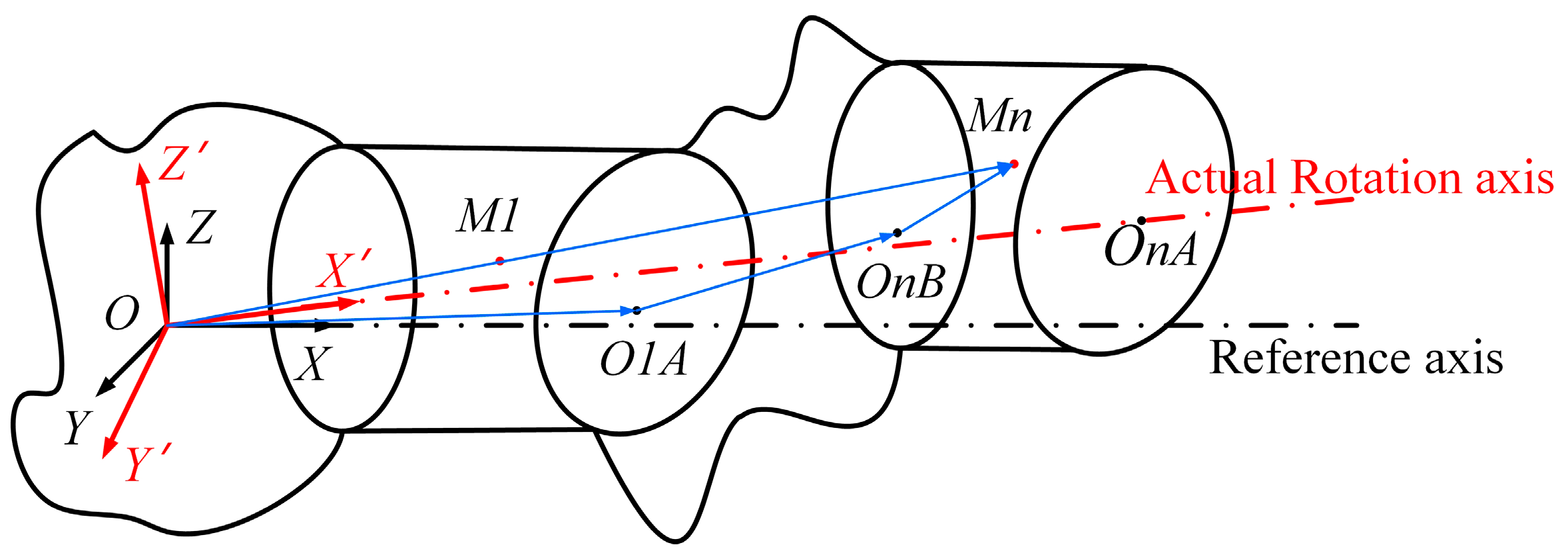
2.1. Dynamic Analysis of Rotor Vibration Response Based on Centroid Transformation
2.2. Assembly Strategy Analysis
2.2.1. First Assembly Strategy: Direct Assembly
2.2.2. Second Assembly Strategy: Minimize Vibration Assembly
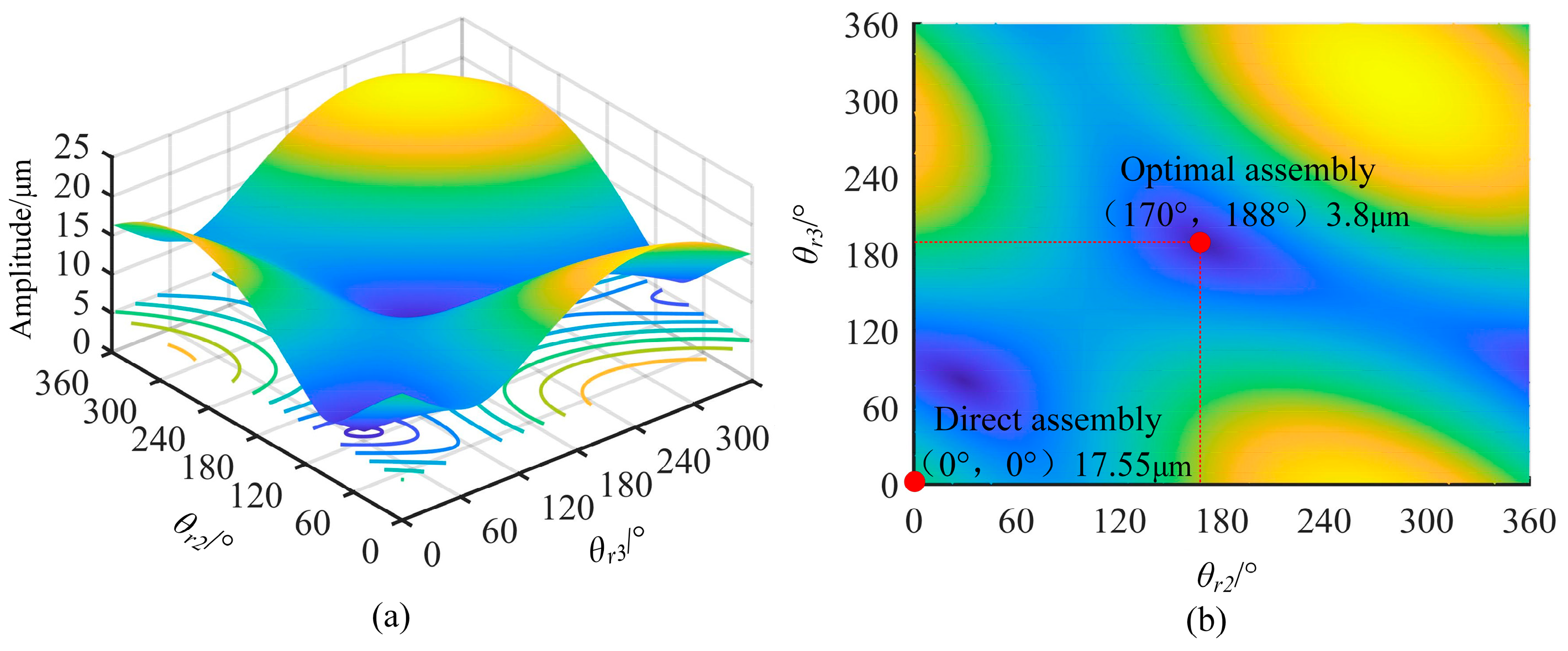
2.2.3. Third Assembly Strategy: Optimal Assembly with Double Constraints
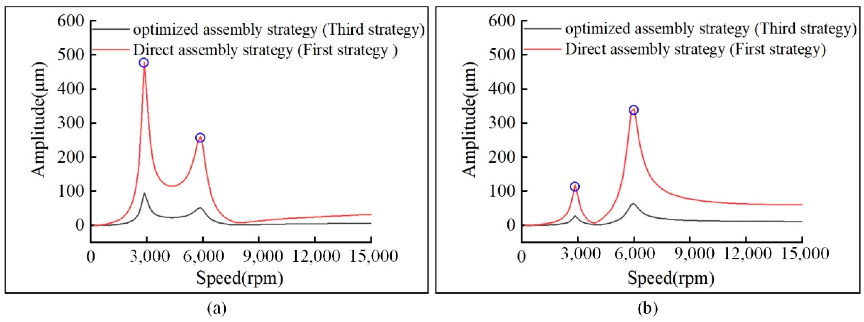
3. Simulation
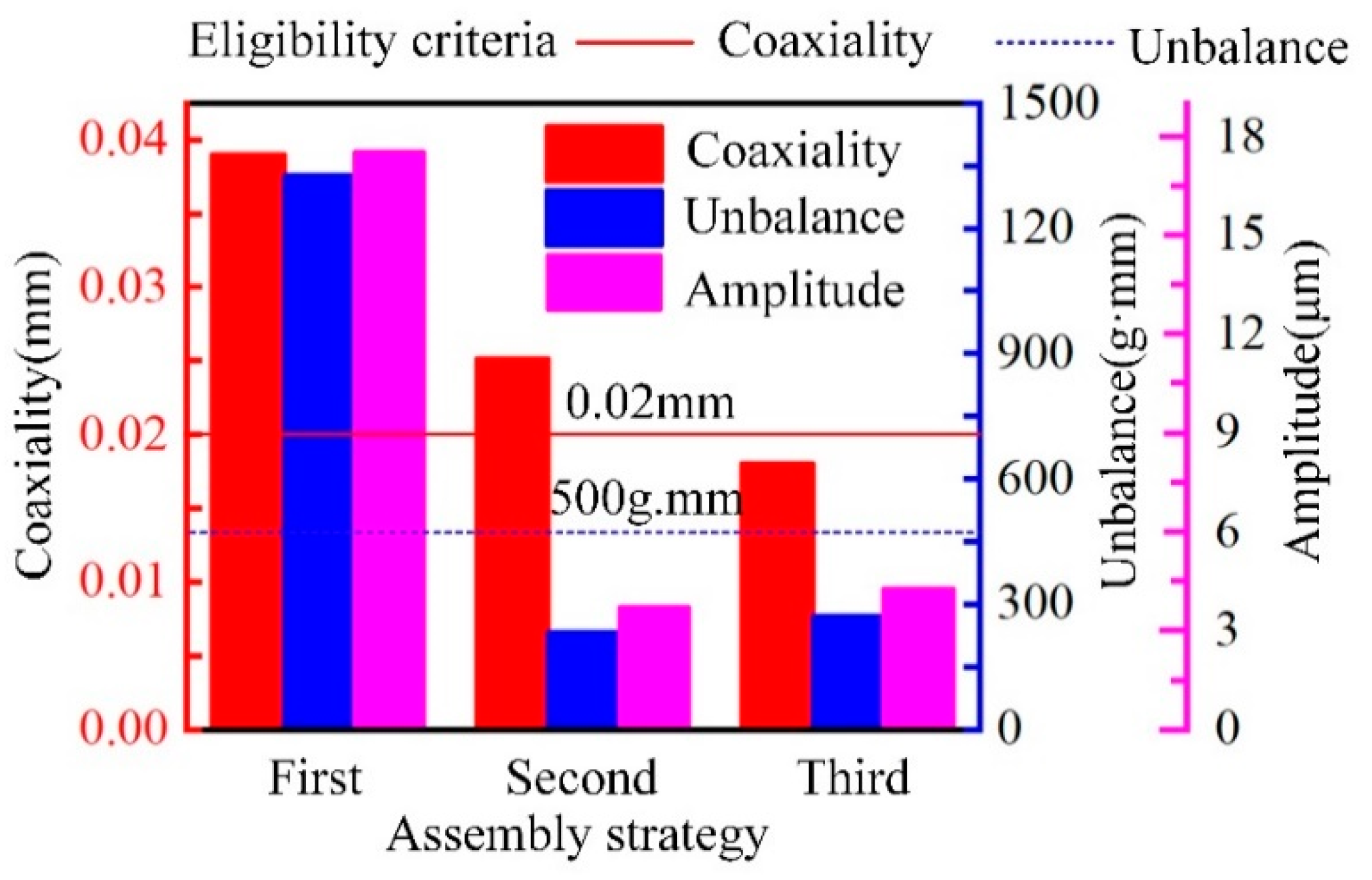
4. Experiment
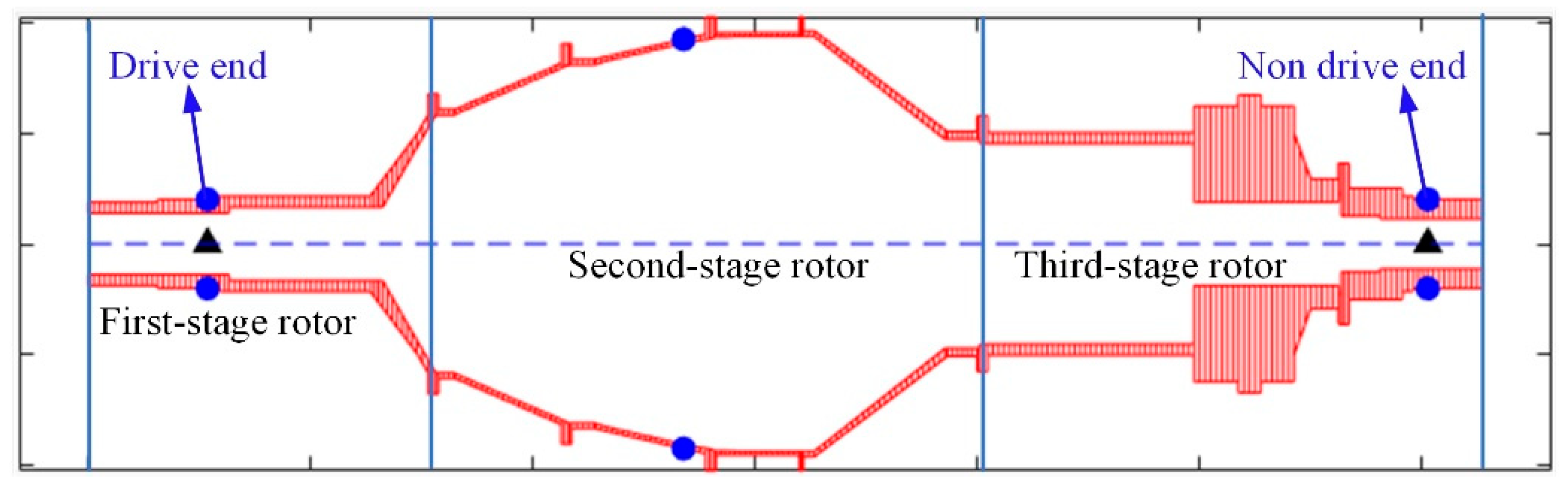
4.1. Parameters Measurement of Rotary Parts Rotors
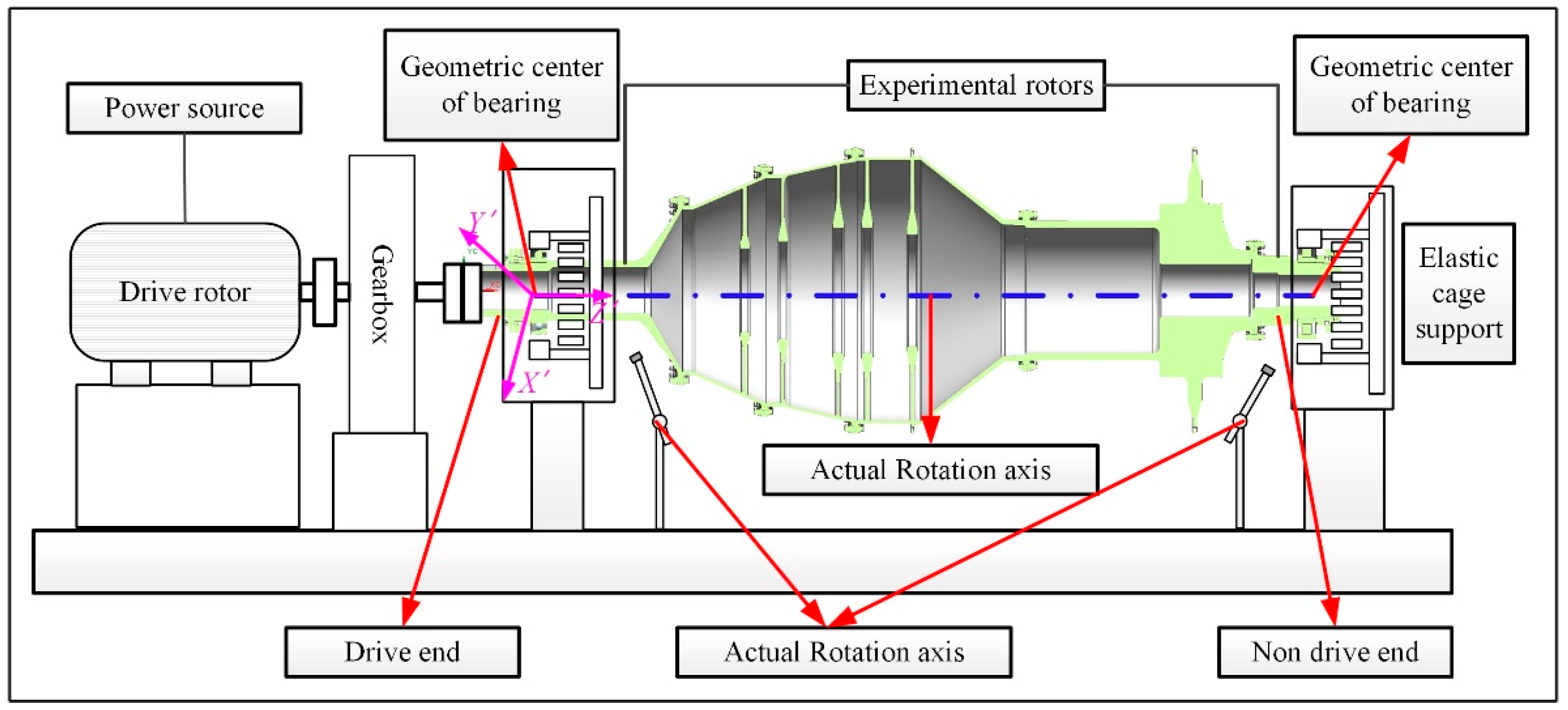
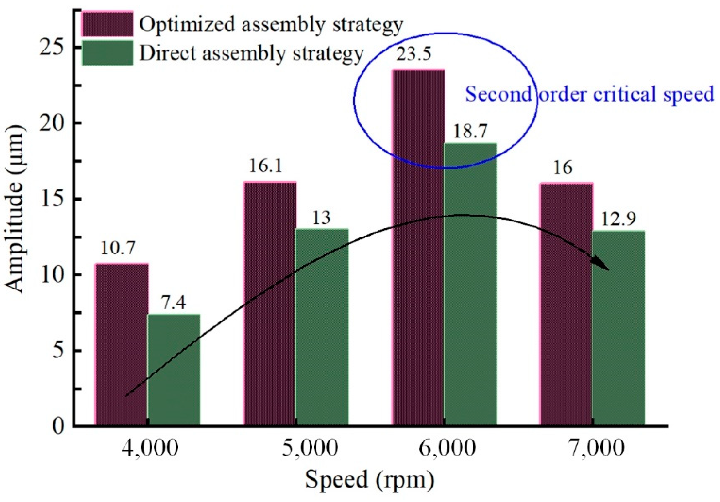
4.2. Vibration Test
5. Conclusions
Author Contributions
Funding
Institutional Review Board Statement
Informed Consent Statement
Data Availability Statement
Acknowledgments
Conflicts of Interest
References
- Yongcun, C.; Sier, D.; Wenhu, Z.; Guoding, C. The impact of roller dynamic unbalance of high-speed cylindrical roller bearing on the cage nonlinear dynamic characteristics. Mech. Mach. Theory 2017, 118, 65–83. [Google Scholar] [CrossRef]
- Cui, Y.; Deng, S.; Niu, R.; Chen, G. Vibration effect analysis of roller dynamic unbalance on the cage of high-speed cylindrical roller bearing. J. Sound Vibr. 2018, 434, 314–335. [Google Scholar] [CrossRef]
- Wang, D.; Wang, N.; Chen, K. Unbalance response of a magnetic suspended dual-rotor system. Proc. Inst. Mech. Eng. Part. G J. Aerosp. Eng. 2019, 233, 5758–5772. [Google Scholar] [CrossRef]
- Wang, H.; Gong, J.; Chen, G. Characteristics analysis of aero-engine whole vibration response with rolling bearing radial clearance. J. Mech. Sci. Technol. 2017, 31, 2129–2141. [Google Scholar] [CrossRef]
- Liu, Y.; Zhang, M.; Sun, C.; Hu, M.; Chen, D.; Liu, Z.; Tan, J. A method to minimize stage-by-stage initial unbalance in the aero engine assembly of multistage rotors. Aerosp. Sci. Technol. 2019, 85, 270–276. [Google Scholar] [CrossRef]
- Hussain, T.; Yang, Z.; Popov, A.A.; Mcwilliam, S. Straight-Build Assembly Optimization: A Method to Minimize Stage-by-Stage Eccentricity Error in the Assembly of Axisymmetric Rigid Components (Two-Dimensional Case Study). J. Manuf. Sci. Eng.-Trans. 2011, 133, 031014. [Google Scholar] [CrossRef]
- Yang, Z.; Mcwilliam, S.; Popov, A.A.; Hussain, T. A probabilistic approach to variation propagation control for straight build in mechanical assembly. J. Mech. Sci. Technol. 2013, 64, 1029–1047. [Google Scholar] [CrossRef]
- Lei, W.; Sun, C.; Tan, J.; Bo, Z.; Gu, W. Improvement of location and orientation tolerances propagation control in cylindrical components assembly using stack-build assembly technique. Assem. Autom. 2015, 35, 358–366. [Google Scholar] [CrossRef]
- Rao, S.S.; Wu, A. Optimum tolerance allocation in mechanical assemblies using an interval method. Eng. Optim. 2005, 37, 237–257. [Google Scholar] [CrossRef]
- Yang, Z.; Mcwilliam, S.; Popov, A.A.; Hussain, T.; Yang, H. Dimensional variation propagation analysis in straight-build mechanical assemblies using a probabilistic approach. J. Manuf. Syst. 2013, 32, 348–356. [Google Scholar] [CrossRef]
- Yang, Z.; Popov, A.A.; Mcwilliam, S. Variation propagation control in mechanical assembly of cylindrical components. J. Manuf. Syst. 2012, 31, 162–176. [Google Scholar] [CrossRef] [Green Version]
- Sun, C.; Wang, L.; Tan, J.; Zhao, B.; Tang, Y. Design of roundness measurement model with multi-systematic error for cylindrical components with large radius. Rev. Sci. Instrum. 2016, 87, 025110. [Google Scholar] [CrossRef]
- Liu, J.; Fa-Yong, W.U.; Wang, J. Optimization Technique of Aeroengine Rotor Assembly. Aeroengine 2014, 40, 75–78. [Google Scholar] [CrossRef]
- Maldonado, D.; Karev, A.; Hagedorn, P.; Ritto, T.G.; Sampaio, R. Analysis of a rotor dynamic system with anisotropy and nonlinearity using the Floquet theory and the method of normal forms. J. Sound Vibr. 2019, 453, 201–213. [Google Scholar] [CrossRef]
- Eissa, M.; Saeed, N.A. Nonlinear vibration control of a horizontally supported Jeffcott-rotor system. J. Vib. Control. 2018, 24, 5898–5921. [Google Scholar] [CrossRef]
- Xu, L.X. A general method for impact dynamic analysis of a planar multi-body system with a rolling ball bearing joint. Nonlinear Dyn. 2014, 78, 857–879. [Google Scholar] [CrossRef]
- Lees, A.W.; Sinha, J.K.; Friswell, M.I. Model-based identification of rotating machines. Mech. Syst. Signal. Proc. 2009, 23, 1884–1893. [Google Scholar] [CrossRef]
- Zhou, S.; Shi, J. Imbalance Estimation for Speed-Varying Rigid Rotors Using Time-Varying Observer. J. Dyn. Syst. Meas. Control Trans. ASME 2001, 123, 637–644. [Google Scholar] [CrossRef]
- Yao, J.; Liu, L.; Yang, F.; Scarpa, F.; Gao, J. Identification and optimization of unbalance parameters in rotor-bearing systems. J. Sound Vibr. 2018, 431, 54–69. [Google Scholar] [CrossRef] [Green Version]
- Chen, G. Vibration modelling and verifications for whole aero-engine. J. Sound Vibr. 2015, 349, 163–176. [Google Scholar] [CrossRef]
- Breńkacz, Ł.; Bagiński, P.; Korbicz, K.J. Vibration damping of the anti-vibration platform intended for use in combination with audio/music devices. J. Vibr. Eng. 2020, 22, 578–593. [Google Scholar] [CrossRef]
- Breńkacz, Ł.; Bagiński, P.; Żywica, G. Experimental Research on Foil Vibrations in a Gas Foil Bearing Carried Out Using an Ultra-High-Speed Camera. Appl. Sci. 2021, 11, 878. [Google Scholar] [CrossRef]
- Yao, H.; Cao, Y.; Ding, Z.; Wen, B. Using grounded nonlinear energy sinks to suppress lateral vibration in rotor systems. Mech. Syst. Signal. Proc. 2019, 124, 237–253. [Google Scholar] [CrossRef]
- Qiu, Y.; Jiang, S. Suppression of low-frequency vibration for rotor-bearing system of flywheel energy storage system. Mech. Syst. Signal. Proc. 2019, 121, 496–508. [Google Scholar] [CrossRef]
- Lusty, C.; Bailey, N.Y.; Keogh, P.S. Control of Flexible Rotor Vibration with Flexibly Mounted Active Magnetic Bearings. IEEE-ASME Trans. Mechatron. 2018, 23, 2870–2880. [Google Scholar] [CrossRef]
- Sun, C.; Liu, Z.; Liu, Y.; Wang, X.; Tan, J. An Adjustment Method of Geometry and Mass Centers for Precision Rotors Assembly. IEEE Access 2019, 7, 169992–170002. [Google Scholar] [CrossRef]


| Rotor Parameter | First-Stage Rotor | Second-Stage Rotor | Third-Stage Rotor |
|---|---|---|---|
| Mass weight/g | 27,400 | 20,000 | 5800 |
| Height/mm | 310 | 500 | 330 |
| Geometric eccentricity error in X direction/mm | 0.001 | 0.001 | 0.001 |
| Geometric eccentricity error in Y direction/mm | 0.002 | 0.002 | 0.002 |
| Geometric eccentricity error in Z direction/mm | 0.002 | 0.002 | 0.002 |
| Perpendicularity/mm | 0.001 | 0.001 | 0.001 |
| Mass eccentricity error in X direction/mm | 0.002 | 0.002 | 0.002 |
| Mass eccentricity error in Y direction/mm | 0.001 | 0.001 | 0.001 |
| Mass eccentricity error in Z direction/mm | 0.001 | 0.001 | 0.001 |
| Lowest tilt point phase/° | 0 | 0 | 0 |
| Rotor Parameter | First-Stage Rotor | Second-Stage Rotor | Third-Stage Rotor |
|---|---|---|---|
| Radius of top face/mm | 43 | 189 | 100 |
| Radius of bottom face /mm | 189 | 100 | 66 |
| Height/mm | 310 | 500 | 330 |
| Geometric eccentricity error in X direction/mm | 0.0026 | 0.0011 | −0.0119 |
| Geometric eccentricity error in Y direction/mm | 0.0419 | 0.0051 | −0.0047 |
| Geometric eccentricity error in Z direction/mm | 0.0021 | 0.0015 | 0.0003 |
| Tilt angle/″ | 2.3 | 3.1 | 0.9 |
| Lowest tilt point phase/° | 220 | 221 | 51 |
| Rotor Parameter | First-Stage Rotor | Second-Stage Rotor | Third-Stage Rotor |
|---|---|---|---|
| Mass weight/g | 27,850 | 19,278 | 53,278 |
| Mass eccentricity error in X direction/mm | 0.0042 | −0.0080 | −0.0042 |
| Mass eccentricity error in Y direction/mm | −0.0039 | −0.0067 | 0.0041 |
| Rotor Parameter | Coaxiality/mm | Unbalance/g·mm | ||
|---|---|---|---|---|
| First Assem-Bly Strategy | Third Assembly Strategy | First Assem-Bly Strategy | Third Assembly Strategy | |
| First-stage rotor | 0.012 | 0.012 | 84.45 | 84.45 |
| Second-stage rotor | 0.068 | 0.030 | 810.41 | 532.65 |
| Third-stage rotor | 0.068 | 0.038 | 2471.51 | 533.82 |
Publisher’s Note: MDPI stays neutral with regard to jurisdictional claims in published maps and institutional affiliations. |
© 2021 by the authors. Licensee MDPI, Basel, Switzerland. This article is an open access article distributed under the terms and conditions of the Creative Commons Attribution (CC BY) license (https://creativecommons.org/licenses/by/4.0/).
Share and Cite
Liu, Y.; Li, R.; Sun, C.; Chen, Z.; Mei, Y.; Xiao, P.; Wang, X.; Li, C. Research on Rotary Parts Vibration Suppression Based on Coaxiality Measurement and Unbalance Constraint. Appl. Sci. 2021, 11, 5747. https://0-doi-org.brum.beds.ac.uk/10.3390/app11125747
Liu Y, Li R, Sun C, Chen Z, Mei Y, Xiao P, Wang X, Li C. Research on Rotary Parts Vibration Suppression Based on Coaxiality Measurement and Unbalance Constraint. Applied Sciences. 2021; 11(12):5747. https://0-doi-org.brum.beds.ac.uk/10.3390/app11125747
Chicago/Turabian StyleLiu, Yongmeng, Ruirui Li, Chuanzhi Sun, Ze Chen, Yingjie Mei, Pinghuan Xiao, Xiaoming Wang, and Chengtian Li. 2021. "Research on Rotary Parts Vibration Suppression Based on Coaxiality Measurement and Unbalance Constraint" Applied Sciences 11, no. 12: 5747. https://0-doi-org.brum.beds.ac.uk/10.3390/app11125747