
The Influence of Hard- and Software Improvement of Intraoral Scanners on the Implant Transfer Accuracy from 2012 to 2021: An In Vitro Study


 ,
,
Abstract
:1. Introduction
2. Materials and Methods
3. Results
4. Discussion
5. Conclusions
Author Contributions
Funding
Institutional Review Board Statement
Informed Consent Statement
Data Availability Statement
Acknowledgments
Conflicts of Interest
Abbreviations
| CMM | Coordinate measurement machine |
| IAIPs | Implant abutment interface points |
| IsB | Intraoral scan body |
| ISC | Intraoral scan |
| IMM | Implant master model |
| IOS | Intraoral scanner |
| RC | reference cube |
References
- Blatz, M.B.; Conejo, J. The Current State of Chairside Digital Dentistry and Materials. Dent. Clin. N. Am. 2019, 63, 175–197. [Google Scholar] [CrossRef]
- Michelinakis, G.; Apostolakis, D.; Kamposiora, P.; Papavasiliou, G.; Ozcan, M. The direct digital workflow in fixed implant prosthodontics: A narrative review. BMC Oral Health 2021, 21, 37. [Google Scholar] [CrossRef]
- Schmidt, A.; Klussmann, L.; Wostmann, B.; Schlenz, M.A. Accuracy of Digital and Conventional Full-Arch Impressions in Patients: An Update. J. Clin. Med. 2020, 9, 688. [Google Scholar] [CrossRef] [Green Version]
- Schmidt, A.; Rein, P.E.; Wostmann, B.; Schlenz, M.A. A comparative clinical study on the transfer accuracy of conventional and digital implant impressions using a new reference key-based method. Clin. Oral Implant. Res. 2021, 32, 460–469. [Google Scholar] [CrossRef]
- Yatmaz, B.B.; Raith, S.; Reich, S. Trueness evaluation of digital impression: The impact of the selection of reference and test object. J. Dent. 2021, 103706. [Google Scholar] [CrossRef] [PubMed]
- Christopoulou, I.; Kappaaklamanos, E.G.; Makrygiannakis, M.A.; Bitsanis, I.; Tsolakis, A.I. Patient-reported experiences and preferences with intraoral scanners: A systematic review. Eur. J. Orthod. 2021. [Google Scholar] [CrossRef]
- Zhang, Y.J.; Shi, J.Y.; Qian, S.J.; Qiao, S.C.; Lai, H.C. Accuracy of full-arch digital implant impressions taken using intraoral scanners and related variables: A systematic review. Int. J. Oral Implantol. 2021, 14, 157–179. [Google Scholar]
- Logozzo, S.; Zanetti, E.M.; Franceschini, G.; Kilpelä, A. Recent advances in dental optics—Part I: 3D intraoral scanners for restorative dentistry. Opt. Laser. Eng. 2014, 54, 203–221. [Google Scholar] [CrossRef]
- Rehmann, P.; Sichwardt, V.; Wostmann, B. Intraoral Scanning Systems: Need for Maintenance. Int. J. Prosthodont. 2017, 30, 27–29. [Google Scholar] [CrossRef] [PubMed] [Green Version]
- Müller, P.; Ender, A.; Joda, T.; Katsoulis, J. Impact of digital intraoral scan strategies on the impression accuracy using the TRIOS Pod scanner. Quintessence Int. 2016, 47, 343–349. [Google Scholar] [CrossRef]
- Ender, A.; Mehl, A. Influence of scanning strategies on the accuracy of digital intraoral scanning systems. Int. J. Comput. Dent. 2013, 16, 11–21. [Google Scholar]
- Rutkunas, V.; Geciauskaite, A.; Jegelevicius, D.; Vaitiekunas, M. Accuracy of digital implant impressions with intraoral scanners. A systematic review. Eur. J. Oral Implantol. 2017, 10 (Suppl. 1), 101–120. [Google Scholar] [PubMed]
- Boeddinghaus, M.; Breloer, E.S.; Rehmann, P.; Wostmann, B. Accuracy of single-tooth restorations based on intraoral digital and conventional impressions in patients. Clin. Oral Investig. 2015, 19, 2027–2034. [Google Scholar] [CrossRef] [PubMed]
- Kuhr, F.; Schmidt, A.; Rehmann, P.; Wöstmann, B. A new method for assessing the accuracy of full arch impressions in patients. J. Dent. 2016, 55, 68–74. [Google Scholar] [CrossRef]
- Giachetti, L.; Sarti, C.; Cinelli, F.; Russo, D.S. Accuracy of Digital Impressions in Fixed Prosthodontics: A Systematic Review of Clinical Studies. Int. J. Prosthodont. 2020, 33, 192–201. [Google Scholar] [CrossRef]
- Keul, C.; Güth, J.F. Accuracy of full-arch digital impressions: An in vitro and in vivo comparison. Clin. Oral Investig. 2020, 24, 735–745. [Google Scholar] [CrossRef]
- Amin, S.; Weber, H.P.; Finkelman, M.; El Rafie, K.; Kudara, Y.; Papaspyridakos, P. Digital vs. conventional full-arch implant impressions: A comparative study. Clin. Oral Implants Res. 2017, 28, 1360–1367. [Google Scholar] [CrossRef]
- Papaspyridakos, P.; Vazouras, K.; Chen, Y.W.; Kotina, E.; Natto, Z.; Kang, K.; Chochlidakis, K. Digital vs. Conventional Implant Impressions: A Systematic Review and Meta-Analysis. J. Prosthodont. 2020, 29, 660–678. [Google Scholar] [CrossRef] [PubMed]
- Haddadi, Y.; Bahrami, G.; Isidor, F. Effect of Software Version on the Accuracy of an Intraoral Scanning Device. Int. J. Prosthodont. 2018, 31, 375–376. [Google Scholar] [CrossRef]
- Shim, J.S.; Lee, J.S.; Lee, J.Y.; Choi, Y.J.; Shin, S.W.; Ryu, J.J. Effect of software version and parameter settings on the marginal and internal adaptation of crowns fabricated with the CAD/CAM system. J. Appl. Oral Sci. 2015, 23, 515–522. [Google Scholar] [CrossRef] [PubMed] [Green Version]
- Vag, J.; Renne, W.; Revell, G.; Ludlow, M.; Mennito, A.; Teich, S.T.; Gutmacher, Z. The effect of software updates on the trueness and precision of intraoral scanners. Quintessence Int. 2021, 52, 2–10. [Google Scholar] [CrossRef]
- Chang, P.K.; Chen, Y.C.; Huang, C.C.; Lu, W.H.; Chen, Y.C.; Tsai, H.H. Distribution of micromotion in implants and alveolar bone with different thread profiles in immediate loading: A finite element study. Int J. Oral Maxillofac. Implants 2012, 27, e96–e101. [Google Scholar] [PubMed]
- Winter, W.; Klein, D.; Karl, M. Micromotion of Dental Implants: Basic Mechanical Considerations. J. Med. Eng. 2013, 2013, 265412. [Google Scholar] [CrossRef] [Green Version]
- Schmidt, A.; Billig, J.W.; Schlenz, M.A.; Rehmann, P.; Wöstmann, B. Influence of the Accuracy of Intraoral Scanbodies on Implant Position: Differences in Manufacturing Tolerances. Int. J. Prosthodont. 2019, 32, 430–432. [Google Scholar] [CrossRef] [PubMed]
- Schmidt, A.; Billig, J.W.; Schlenz, M.A.; Wöstmann, B. Do different methods of digital data analysis lead to different results? Int. J. Comput. Dent. 2021, 24, 157–164. [Google Scholar]
- Schmidt, A.; Billig, J.W.; Schlenz, M.A.; Wöstmann, B. The Influence of Using Different Types of Scan Bodies on the Transfer Accuracy of Implant Position: An In Vitro Study. Int. J. Prosthodont. 2021, 34, 254–260. [Google Scholar] [CrossRef] [PubMed]
- International Organization for Standardization. Accuracy (Trueness and Precision) of Measurement Methods and Results—Part 1: General Principles and Definitions. ISO 5725-1:1994. 1994. Available online: https://www.iso.org/obp/ui/#iso:std:iso:5725:-1:ed-1:v1:en (accessed on 10 June 2021).
- Schlenz, M.A.; Schubert, V.; Schmidt, A.; Wostmann, B.; Ruf, S.; Klaus, K. Digital versus Conventional Impression Taking Focusing on Interdental Areas: A Clinical Trial. Int. J. Environ. Res. Public Health 2020, 17, 4725. [Google Scholar] [CrossRef] [PubMed]
- Tewes, M.; Berner, M. Device, Method and System for Generating Dynamic Projection Patterns in a Confocal Camera. U.S. Patent US 16/003628, 12 December 2019. [Google Scholar]
- Flügge, T.; van der Meer, W.J.; Gonzalez, B.G.; Vach, K.; Wismeijer, D.; Wang, P. The accuracy of different dental impression techniques for implant-supported dental prostheses: A systematic review and meta-analysis. Clin. Oral Implants Res. 2018, 29 (Suppl. 16), 374–392. [Google Scholar] [CrossRef] [Green Version]
- Moreira, A.H.; Rodrigues, N.F.; Pinho, A.C.; Fonseca, J.C.; Vilaca, J.L. Accuracy Comparison of Implant Impression Techniques: A Systematic Review. Clin. Implant Dent. Relat. Res. 2015, 17 (Suppl. 2), e751–e764. [Google Scholar] [CrossRef] [Green Version]
- Stimmelmayr, M.; Erdelt, K.; Güth, J.F.; Happe, A.; Beuer, F. Evaluation of impression accuracy for a four-implant mandibular model--a digital approach. Clin. Oral Investig. 2012, 16, 1137–1142. [Google Scholar] [CrossRef]
- Ender, A.; Attin, T.; Mehl, A. In vivo precision of conventional and digital methods of obtaining complete-arch dental impressions. J. Prosthet. Dent. 2016, 115, 313–320. [Google Scholar] [CrossRef] [Green Version]
- Ender, A.; Mehl, A. Full arch scans: Conventional versus digital impressions-An in-vitro study. Int. J. Comput. Dent. 2011, 14, 11–21. [Google Scholar]
- Gan, N.; Xiong, Y.; Jiao, T. Accuracy of Intraoral Digital Impressions for Whole Upper Jaws, Including Full Dentitions and Palatal Soft Tissues. PLoS ONE 2016, 11, e0158800. [Google Scholar] [CrossRef] [Green Version]
- Ameza-Lasuen, X.; Iturrate-Mendieta, M.; Oriozabala-Brit, J.A.; Garikano-Osinaga, X.; Martin-Amundarain, I.; Solaberrieta-Mendez, E. Best-Fit Alignment in the Digital Dental Workflow. In Advances in Design Engineering: Proceedings of the XXIX International Congress INGEGRAF; Cavas-Martínez, F., Sanz-Adan, F., Morer Camo, P., Lostado Lorza, R., Santamaría Peña, J., Eds.; Springer: Berlin/Heidelberg, Germany, 2020; pp. 202–211. [Google Scholar]
- Ender, A.; Mehl, A. Accuracy of complete-arch dental impressions: A new method of measuring trueness and precision. J. Prosthet. Dent. 2013, 109, 121–128. [Google Scholar] [CrossRef] [Green Version]
- Aswani, K.; Wankhade, S.; Khalikar, A.; Deogade, S. Accuracy of an intraoral digital impression: A review. J. Indian Prosthodont. Soc. 2020, 20, 27–37. [Google Scholar] [CrossRef] [PubMed]
- Gimenez, B.; Ozcan, M.; Martinez-Rus, F.; Pradies, G. Accuracy of a digital impression system based on active wavefront sampling technology for implants considering operator experience, implant angulation, and depth. Clin. Implant Dent. Relat. Res. 2015, 17 (Suppl. 1), e54–e64. [Google Scholar] [CrossRef] [PubMed]
- Gimenez-Gonzalez, B.; Hassan, B.; Ozcan, M.; Pradies, G. An In Vitro Study of Factors Influencing the Performance of Digital Intraoral Impressions Operating on Active Wavefront Sampling Technology with Multiple Implants in the Edentulous Maxilla. J. Prosthodont. 2017, 26, 650–655. [Google Scholar] [CrossRef] [PubMed]
- Medina-Sotomayor, P.; Pascual-Moscardo, A.; Camps, I. Accuracy of four digital scanners according to scanning strategy in complete-arch impressions. PLoS ONE 2018, 13, e0202916. [Google Scholar] [CrossRef] [Green Version]
- Medina-Sotomayor, P.; Pascual-Moscardo, A.; Camps, I. Relationship between resolution and accuracy of four intraoral scanners in complete-arch impressions. J. Clin. Exp. Dent. 2018, 10, e361–e366. [Google Scholar] [CrossRef] [Green Version]
- Vandeweghe, S.; Vervack, V.; Dierens, M.; De Bruyn, H. Accuracy of digital impressions of multiple dental implants: An in vitro study. Clin. Oral Implants Res. 2017, 28, 648–653. [Google Scholar] [CrossRef]
- Jeong, I.D.; Lee, J.J.; Jeon, J.H.; Kim, J.H.; Kim, H.Y.; Kim, W.C. Accuracy of complete-arch model using an intraoral video scanner: An in vitro study. J. Prosthet Dent. 2016, 115, 755–759. [Google Scholar] [CrossRef]
- Moura, R.V.; Kojima, A.N.; Saraceni, C.H.C.; Bassolli, L.; Balducci, I.; Ozcan, M.; Mesquita, A.M.M. Evaluation of the Accuracy of Conventional and Digital Impression Techniques for Implant Restorations. J. Prosthodont. 2019, 28, e530–e535. [Google Scholar] [CrossRef]
- Menini, M.; Setti, P.; Pera, F.; Pera, P.; Pesce, P. Accuracy of multi-unit implant impression: Traditional techniques versus a digital procedure. Clin. Oral Investig. 2018, 22, 1253–1262. [Google Scholar] [CrossRef]
- Rutkunas, V.; Gedrimiene, A.; Adaskevicius, R.; Al-Haj Husain, N.; Ozcan, M. Comparison of the Clinical Accuracy of Digital and Conventional Dental Implant Impressions. Eur. J. Prosthodont. Restor. Dent. 2020, 28, 173–181. [Google Scholar] [CrossRef]
- Chew, A.A.; Esguerra, R.J.; Teoh, K.H.; Wong, K.M.; Ng, S.D.; Tan, K.B. Three-Dimensional Accuracy of Digital Implant Impressions: Effects of Different Scanners and Implant Level. Int. J. Oral Maxillofac. Implants 2017, 32, 70–80. [Google Scholar] [CrossRef] [PubMed]
- Flügge, T.V.; Att, W.; Metzger, M.C.; Nelson, K. Precision of Dental Implant Digitization Using Intraoral Scanners. Int. J. Prosthodont. 2016, 29, 277–283. [Google Scholar] [CrossRef] [PubMed] [Green Version]
- Rech-Ortega, C.; Fernandez-Estevan, L.; Sola-Ruiz, M.F.; Agustin-Panadero, R.; Labaig-Rueda, C. Comparative in vitro study of the accuracy of impression techniques for dental implants: Direct technique with an elastomeric impression material versus intraoral scanner. Med. Oral Patol. Oral Cir. Bucal 2019, 24, e89–e95. [Google Scholar] [CrossRef] [PubMed]
- Revilla-Leon, M.; Att, W.; Ozcan, M.; Rubenstein, J. Comparison of conventional, photogrammetry, and intraoral scanning accuracy of complete-arch implant impression procedures evaluated with a coordinate measuring machine. J. Prosthet. Dent. 2021, 125, 470–478. [Google Scholar] [CrossRef]
- Gedrimiene, A.; Adaskevicius, R.; Rutkunas, V. Accuracy of digital and conventional dental implant impressions for fixed partial dentures: A comparative clinical study. J. Adv. Prosthodont. 2019, 11, 271–279. [Google Scholar] [CrossRef] [PubMed] [Green Version]
- O’Toole, S.; Osnes, C.; Bartlett, D.; Keeling, A. Investigation into the accuracy and measurement methods of sequential 3D dental scan alignment. Dent. Mater. 2019, 35, 495–500. [Google Scholar] [CrossRef]
- Mizumoto, R.M.; Yilmaz, B.; McGlumphy, E.A., Jr.; Seidt, J.; Johnston, W.M. Accuracy of different digital scanning techniques and scan bodies for complete-arch implant-supported prostheses. J. Prosthet. Dent. 2020, 123, 96–104. [Google Scholar] [CrossRef] [PubMed] [Green Version]


| Scanner Family | Type | Software Version | Release Date | Label |
|---|---|---|---|---|
| True Definition Scanner | True Definition scanner (Cart version) | 4.0.3 | 2013-04 | TD_4.1 |
| True Definition scanner (Cart version) | 5.4 | 2018-07 | TD_5.4 | |
| True Definition scanner (Portable version) | 5.4 | 2018-07 | TDpb_5.4 | |
| TRIOS | TRIOS II | 2013-01 | 2013-01 | TR2 |
| TRIOS 4 | 19.2.4 | 2020-12 | TR4 | |
| CEREC | CEREC Omnicam | 4.2.1.61068 | 2012-04 | OC_4.2 |
| CEREC Omnicam | 4.6.1.152739 | 2018-05 | OC_4.6 | |
| CEREC Primescan | 5.1.0.190461 | 2020-05 | PS |
| Impression Method | p-Value | ||||
|---|---|---|---|---|---|
| Trueness/Precision (Mean [µm] ± Standard Deviation [µm]) | |||||
| Implant Position | |||||
| Hardware/Software-Version (Old—New) | 16 | 14 | 25 | 26 | |
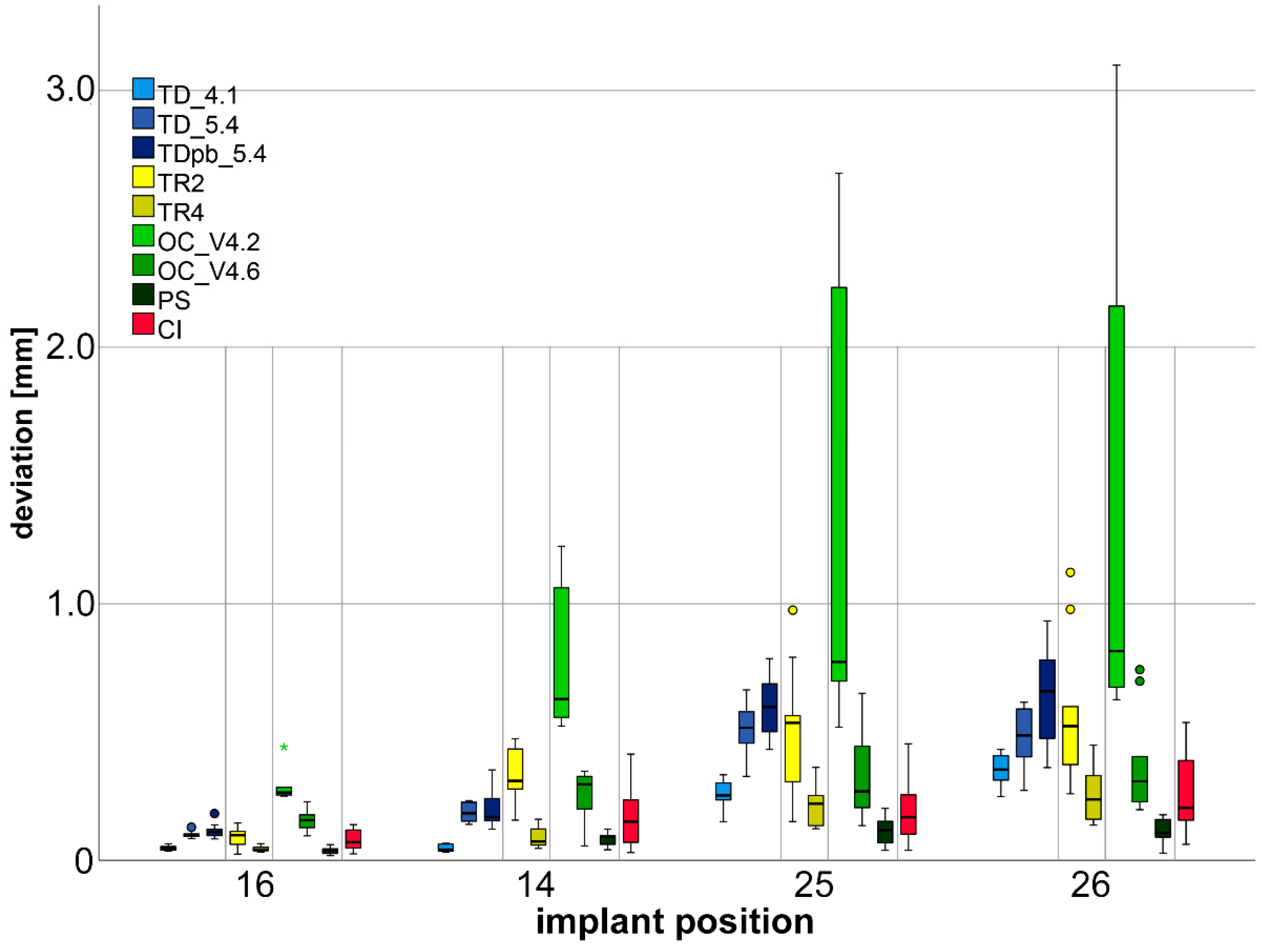
| Three-dimensional Deviations | TD_4.1—TD_5.4 | <0.001/0.672 (0.047 ± 0.009–0.101 ± 0.013) | <0.001/0.010 (0.047 ± 0.014–0.185 ± 0.035) | <0.001/0.024 (0.258 ± 0.052–0.515 ± 0.103) | 0.013/0.135 (0.355 ± 0.062–0.483 ± 0.110) |
| TD_4.1—TDpb_5.4 | <0.001/0.082 (0.047 ± 0.009–0.115 ± 0.028) | <0.001/0.009 (0.047 ± 0.014–0.192 ± 0.069) | <0.001/0.007 (0.258 ± 0.052–0.597 ± 0.120) | 0.002/0.010 (0.355 ± 0.062–0.632 ± 0.184) | |
| TR2—TR4 | 0.006/0.004 (0.089 ± 0.036–0.044 ± 0.011) | <0.001/0.009 (0.335 ± 0.105–0.092 ± 0.043) | 0.002/0.035 (0.516 ± 0.242–0.214 ± 0.072) | 0.001/0.071 (0.574 ± 0.274–0.258 ± 0.100) | |
| OC_4.2—OC_4.6 | <0.001/0.863 (0.282 ± 0.058–0.154 ± 0.039) | <0.001/0.002 (0.747 ± 0.262–0.256 ± 0.092) | <0.001/<0.001 (1.260 ± 0.889–0.335 ± 0.173) | 0.001/<0.001 (1.356 ± 1.023–0.370 ± 0.195) | |
| OC_4.2—PS | <0.001/0.163 (0.282 ± 0.058–0.038 ± 0.014) | <0.001/<0.001 (0.747 ± 0.262–0.085 ± 0.024) | <.001/<0.001 (1.260 ± 0.889–0.115 ± 0.053) | <0.001/<0.001 (1.356 ± 1.023–0.110 ± 0.049) | |
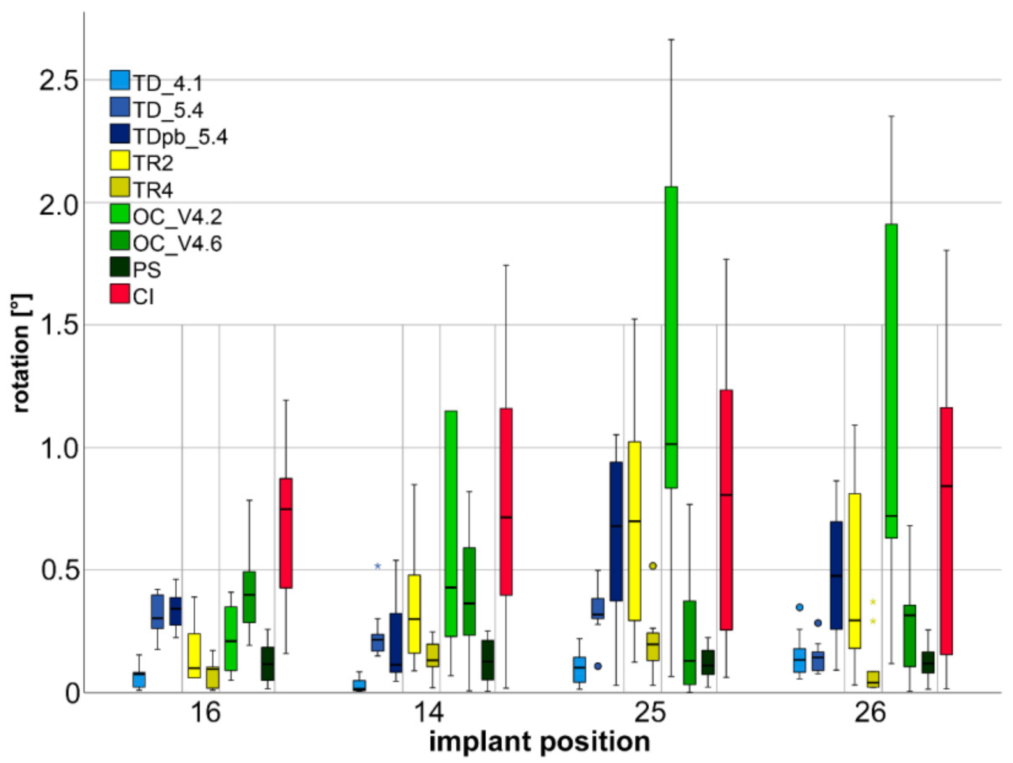
| Rotational Deviations | TD_4.1—TD_5.4 | <0.001/0.099 (0.067 ± 0.044–0.312 ± 0.078) | <0.001/0.099 (0.031 ± 0.029–0.237 ± 0.108) | 0.001/0.605 (0.108 ± 0.073–0.335 ± 0.108) | 0.821/0.435 (0.152 ± 0.090–0.143 ± 0.065) |
| TD_4.1—TDpb_5.4 | <0.001/0.123 (0.067 ± 0.044–0.339 ± 0.076) | 0.001/0.001 (0.031 ± 0.029–0.211 ± 0.182) | 0.004/0.004 (0.108 ± 0.073–0.640 ± 0.354) | 0.005/0.012 (0.152 ± 0.090–0.494 ± 0.266) | |
| TR2—TR4 | 0.324/0.026 (0.161 ± 0.125–0.084 ± 0.058) | 0.012/0.009 (0.349 ± 0.233–0.139 ± 0.073) | 0.012/<0.001 (0.709 ± 0.491–0.206 ± 0.131) | 0.008/0.004 (0.067 ± 0.044–0.339 ± 0.076) | |
| OC_4.2—OC_4.6 | 0.021/0.718 (0.218 ± 0.138–0.418 ± 0.184) | 0.405/0.003 (1.567 ± 2.414–0.404 ± 0.247) | 0.001/0.008 (1.307 ± 0.877–0.241 ± 0.272) | 0.006/0.001 (1.083 ± 0.814–0.313 ± 0.221) | |
| OC_4.2—PS | 0.130/0.030 (0.218 ± 0.138–0.122 ± 0.083) | 0.008/0.002 (1.567 ± 2.414–0.131 ± 0.088) | 0.002/0.001 (1.307 ± 0.877–0.123 ± 0.067) | 0.001/<0.001 (1.083 ± 0.814–0.123 ± 0.070) | |
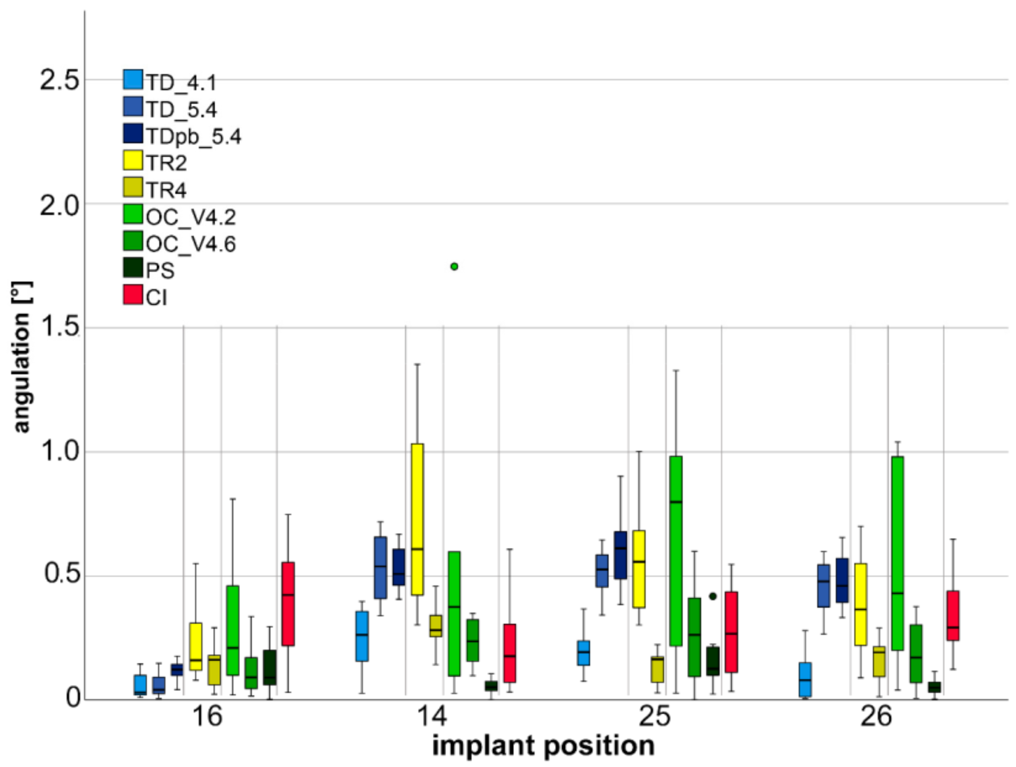
| Angulation Deviations | TD_4.1—TD_5.4 | 0.471/0.724 (0.052 ± 0.047–0.058 ± 0.044) | <0.001/0.681 (0.251 ± 0.119–0.541 ± 0.132) | <0.001/0.525 (0.194 ± 0.082–0.515 ± 0.097) | <0.001/0.638 (0.101 ± 0.092–0.453 ± 0.105) |
| TD_4.1—TDpb_5.4 | 0.006/0.487 (0.052 ± 0.047–0.118 ± 0.041) | <0.001/0.401 (0.251 ± 0.119–0.526 ± 0.089) | <0.001/0.072 (0.194 ± 0.082–0.601 ± 0.162) | <0.001/0.210 (0.101 ± 0.092–0.477 ± 0.111) | |
| TR2—TR4 | 0.290/0.090 (0.219 ± 0.146–0.139 ± 0.074) | 0.004/0.005 (0.685 ± 0.352–0.299 ± 0.100) | <0.001/0.008 (0.567 ± 0.238–0.130 ± 0.069) | 0.015/0.007 (0.374 ± 0.224–0.159 ± 0.083) | |
| OC_4.2—OC_4.6 | 0.096/0.007 (0.318 ± 0.296–0.121 ± 0.104) | 0.705/0.008 (0.569 ± 0.658–0.236 ± 0.087) | 0.059/0.010 (0.663 ± 0.448–0.275 ± 0.216) | 0.054/0.010 (0.531 ± 0.399–0.183 ± 0.139) | |
| OC_4.2—PS | 0.151/0.005 (0.318 ± 0.296–0.120 ± 0.092) | 0.019/0.003 (0.569 ± 0.658–0.055 ± 0.039) | 0.023/<0.001 (0.663 ± 0.448–0.152 ± 0.114) | 0.002/<0.001 (0.531 ± 0.399–0.053 ± 0.031) | |
Publisher’s Note: MDPI stays neutral with regard to jurisdictional claims in published maps and institutional affiliations. |
© 2021 by the authors. Licensee MDPI, Basel, Switzerland. This article is an open access article distributed under the terms and conditions of the Creative Commons Attribution (CC BY) license (https://creativecommons.org/licenses/by/4.0/).
Share and Cite
Schmidt, A.; Schlenz, M.A.; Liu, H.; Kämpe, H.S.; Wöstmann, B. The Influence of Hard- and Software Improvement of Intraoral Scanners on the Implant Transfer Accuracy from 2012 to 2021: An In Vitro Study. Appl. Sci. 2021, 11, 7166. https://0-doi-org.brum.beds.ac.uk/10.3390/app11157166
Schmidt A, Schlenz MA, Liu H, Kämpe HS, Wöstmann B. The Influence of Hard- and Software Improvement of Intraoral Scanners on the Implant Transfer Accuracy from 2012 to 2021: An In Vitro Study. Applied Sciences. 2021; 11(15):7166. https://0-doi-org.brum.beds.ac.uk/10.3390/app11157166
Chicago/Turabian StyleSchmidt, Alexander, Maximiliane Amelie Schlenz, Haoyu Liu, Holger Sebastian Kämpe, and Bernd Wöstmann. 2021. "The Influence of Hard- and Software Improvement of Intraoral Scanners on the Implant Transfer Accuracy from 2012 to 2021: An In Vitro Study" Applied Sciences 11, no. 15: 7166. https://0-doi-org.brum.beds.ac.uk/10.3390/app11157166