
Fast Stepwise Inertial Control Scheme of a DFIG for Reducing Second Frequency Drop


1
School of Electrical Engineering, Nantong University, Nantong 226019, China
2
Key Laboratory of Modern Power System Simulation and Control & Renewable Energy Technology Ministry of Education, Northeast Electric Power University, Jilin 132012, China
*
Authors to whom correspondence should be addressed.
Appl. Sci. 2021, 11(17), 8259; https://0-doi-org.brum.beds.ac.uk/10.3390/app11178259
Submission received: 24 July 2021
/
Revised: 29 August 2021
/
Accepted: 1 September 2021
/
Published: 6 September 2021
(This article belongs to the Section Energy Science and Technology)
Abstract
:With the fast growth in the penetration of wind power, doubly fed induction generators (DFIGs) are recommended for their ability to enforce grid codes that provide inertial control services by releasing rotational energy. However, after supporting the system frequency, a second frequency drop (SFD) is prone to occurring to regain the rotor speed caused by the sudden reduction in output. In this article, we propose a torque limit-based fast stepwise inertial control scheme of a DFIG using a piecewise reference function for reducing the SFD while preserving the frequency nadir (FN) with less rotor energy released. To achieve the first objective, the power reference increases to the torque limit and then decays with the rotor speed toward the preset operating point. To achieve the second objective, the power reference smoothly lessens over time based on the exponential function. The performance of the proposed stepwise inertial control strategy was studied under various scenarios, including constant wind speed and ramp down wind speed conditions. The test results demonstrated that the frequency stability is preserved during the frequency support phase, while the second frequency drop and mechanical stress on the wind turbine reduce during the rotor speed restoration phase when the DFIG implements the proposed stepwise inertial control scheme.
1. Introduction
The increase in the penetration of renewable energy in electric power systems is expected and planned. Wind power generation has the highest proportion of employment and potential for renewable energy generation. However, wind power generation is a power electronic-based resource that minimally contributes to the inertia response of electric power systems. In addition, increasing the amount of wind power generation can replace traditional synchronous generators (TSGs), leading to low system inertia and primary frequency response [1,2,3,4,5]. In a low-inertia electric power system, an insufficient inertia response increases the rate of change of frequency and the maximum frequency deviation [6,7,8].
In a traditional electric power system, a frequency disturbance, including load connection or generator tripping, reduces the system frequency since TSGs immediately respond to the power imbalance. Initially, the inertia of TSGs supplies the deficit power of the electric power system, and after a few seconds, the generator’s governor response activates to prevent the system frequency from further decreasing, thereby stabilizing the system frequency [9]. In a high wind power penetration electric power system, low inertia response and primary frequency response increase the maximum frequency deviation, which drops below the reliability standard. A wide-area power failure may occur during the activation of under-frequency relays [10]. To solve this frequency stability issue, the fast frequency response (FFR) of the wind turbine generators (WTGs), which improves the lower frequency, was introduced as an auxiliary service [11,12,13,14,15,16,17,18,19,20,21,22,23,24,25,26].
The present strategies of the WTGs for providing FFR are roughly divided into two types based on their input signals: frequency-based FFR and fixed-trajectory FFR [27,28,29,30,31,32,33]. The use of frequency based FFR modifies the additional control signals to imitate the inertial response and emulate the droop response based on frequency deviation [27,28,29]. The authors of [7] suggest a timing-varying droop control coefficient to reduce the SFD. An optimized power point tracking method is suggested, the coefficient of the optimized power point tracking scheme is defined based on the frequency deviation and rate of change of frequency [30]. Fixed trajectory FFR is determined by the predefined power reference rather than the measured frequency; it can also sustain the system frequency better than the frequency-based FFR [31]. Nevertheless, after sustaining the grid frequency, the rotor speed is required to regain optimal speed; this process creates a secondary dip in the system frequency [32]. To lessen the depth of the SFD, the authors of [33] suggested a power reference that decays in a ramp manner. Regaining rotor speed addresses a small constant power reference, reducing the depth of the SFD [34,35]. However, it is difficult to counterbalance the performance of the second frequency drop and rotor speed recovery. In addition, to reduce the SFD, the authors of [36] suggest a power reference based on mechanical power. However, it is difficult to obtain accurate mechanical power information. Therefore, a two-stage variable coefficient-based controller was constructed for DFIGs [37]. However, the effectiveness of the two-stage scheme strongly relies on the predetermined training of the fuzzy controller. Furthermore, the rotor speed is regained by adjusting the setting of the primary frequency response, and an energy storage system counterbalances the absorbed power. However, these two strategies require more investment.
We suggest a fast stepwise inertial control scheme of a DFIG to preserve the FN with less energy released and reduce both the depth of the SFD and the mechanical stress on the wind turbine. A piecewise function for the frequency support phase and rotor speed recovery phase is needed to address these issues. The benefits of the proposed stepwise inertial control scheme are indicated by various wind speed conditions.
2. Doubly-Fed Induction Generator Model
Based on the theory of aerodynamics, the mechanical power of the wind turbine is a function of air density (ρ), power coefficient (cp), rotor radius (R), and wind speed (vw):
where β is the pitch angle and λ is the tip-speed ratio.
The mechanical dynamics are displayed in a two-mass shaft model, as indicated by the following equations [36]:
where Tm is the mechanical torque from the turbine; Tem is the generator electrical torque, Ht is inertia from the turbine; Hg is the generator inertia constant; Tls and Ths are the torques of the low-speed and high-speed shafts, respectively; ωt is the turbine rotor speed; ωr is the generator rotor speed; K is the spring constant; θt and θls are the torsional twists of the rotor and low-speed shaft, respectively; B and ωls are the damping constant and rotor speed of the low-speed shaft, respectively.
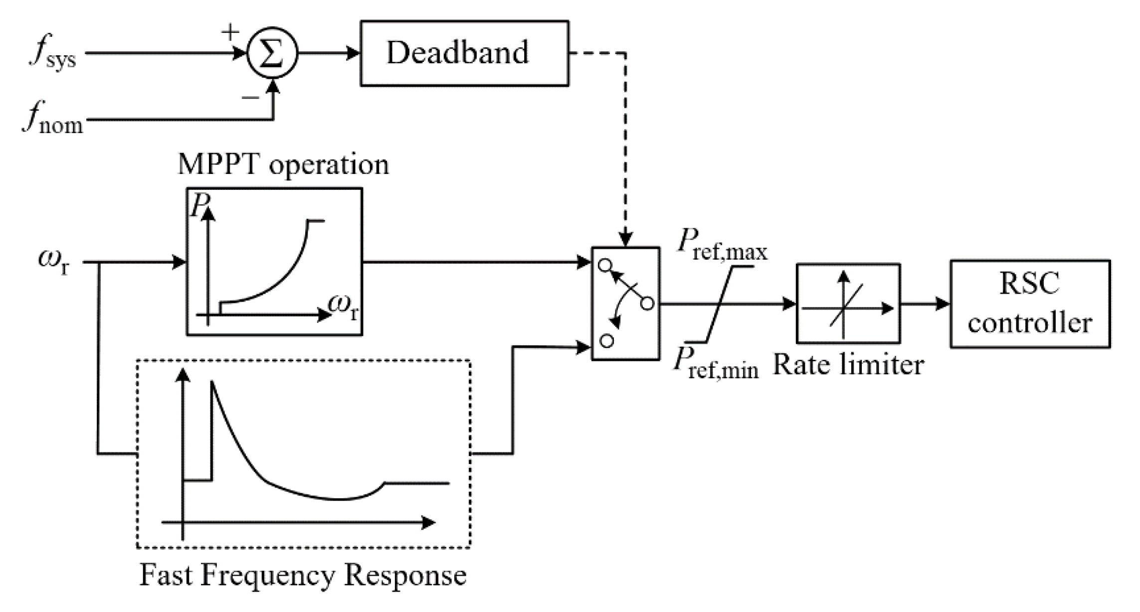
Figure 1 illustrates the vector control of the rotor side converter, which adjusts the voltage and active power injected into the grid through the inner current controller.
In (1), the DFIG captures the maximum power from wind. Substituting (4) into (1), the expression of the power reference for MPPT operation, PMPPT, is described as:
where kg is set to 0.512. In addition, cP, max is the maximum value of cP and is set to 0.5. λopt is the optimal tip-speed ratio and is set to 9.95.
3. Frequency Support Schemes of a DFIG
When implementing the frequency support, the relationship between ΔPDFIG and rotor speed of the DFIG is represented as:
where ΔPDFIG and JDFIG are the active power variation and moment of the DFIG, respectively.
According to the definition of inertia constant by the synchronous generator, the inertia constant of the DFIG (HDFIG) is expressed as:
where ωn and SDFIG are the rated rotor speed and rated capacity of the DFIG, respectively.
Rearranging (9), and converting to a per unit (p.u.) system:
where ΔPDFIG_pu and ωpu are ΔPDFIG and the rotor speed of the DFIG in p.u., respectively.
As reported in [38], the system frequency in p.u. is the same as ωpu; therefore, the expression of (11) can be modified as a function of the system frequency, as follows:
After integrating (12), the instantaneous frequency in p.u. is derived as:
where fpu(t) and fpu(t + ∆t) are the grid frequencies at t and t + ∆t, respectively. Then, (13) is rearranged as:
Hence, (14) illustrates that the DFIG sustains the system frequency during a frequency disturbance. During the frequency support phase (FSP), the DFIG provides a higher ∆PDFIG_pu; therefore, the maximum frequency deviation reduces.
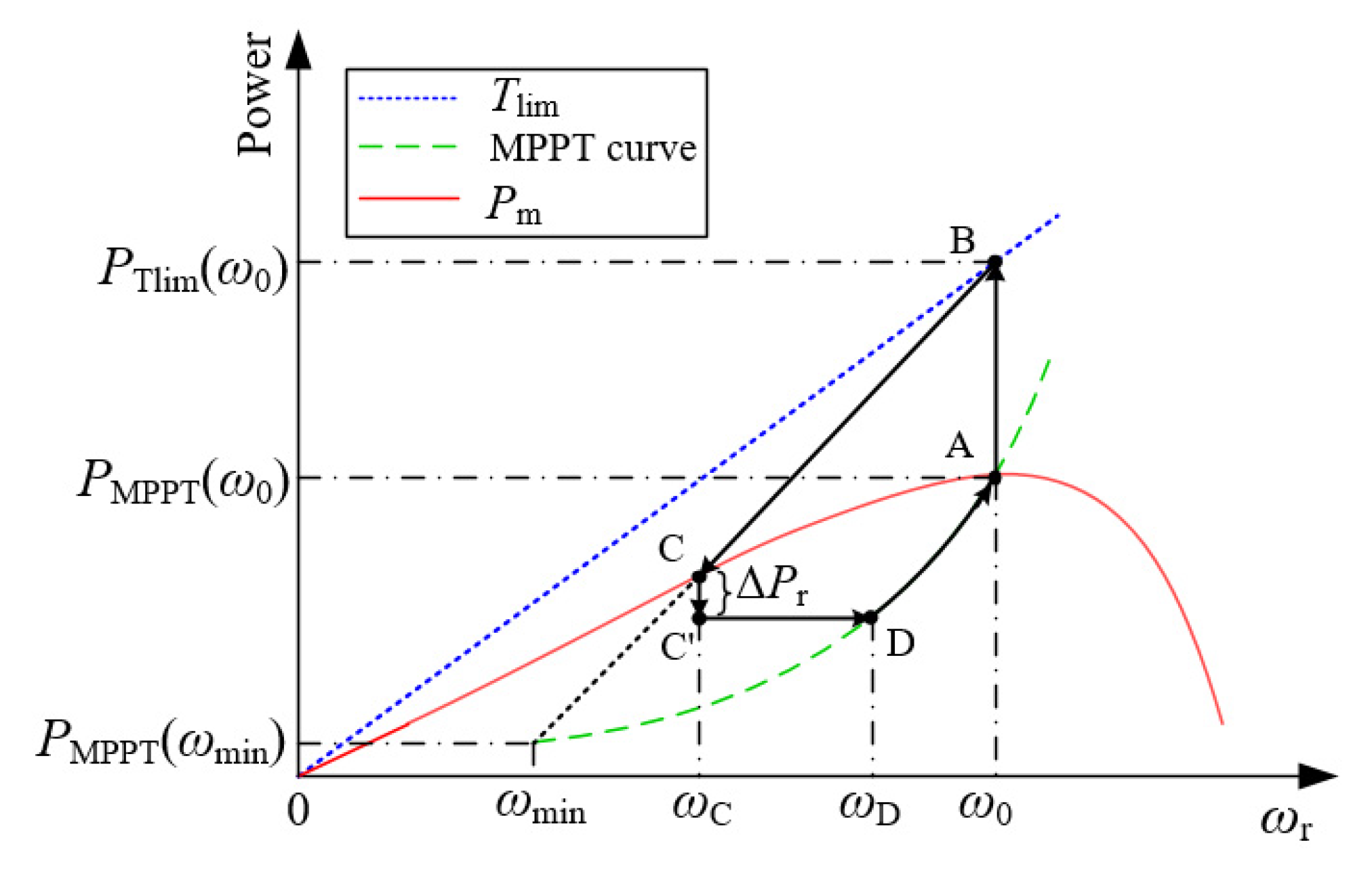
3.1. Conventional Stepwise Inertial Control Scheme
Figure 2 illustrates the structure of the conventional stepwise inertial control scheme, which consists of two phases demonstrated by segment A-B-C-C’-D: a frequency support phase (FSP, operating point A to operating point C) and rotor speed recovery phase (RSRP, operating point C to operating point D). When a frequency disturbance occurs, the DFIG rapidly increases its output power (Pset) to PTlim(ω0) (the torque limit at ω0) to reduce the maximum frequency deviation. This process corresponds to segment A-B in Figure 2. To prevent the rotor speed from stalling, Pset decreases with the rotor speed, which is defined in (15).
Based on the swing equation, the rotor speed increases since the output power of the DFIG is more than the mechanical power, and ωr converges to operating point C, which represents the intersection of (15) and the Pm curve. Thus, the conventional stepwise inertial control scheme prevents the stalling of the wind turbine. However, during the rotor speed convergence stage, considerable energy is released into the grid.
In the RSRP, to regain the rotor speed, Pref should decrease to lower than the mechanical input power. To this end, the conventional stepwise inertial control scheme instantly reduces the reference to Pset(ωC) – ∆Pr, which is maintained until Pset meets the PMPPT curve. The power reference for segment C-C’-D-A is represented in (16) and (17).
As indicated in (14), the rapid and large change in ∆PDFIG_pu significantly affects the system frequency; this signifies that using large ∆Pr produces a severe depth of the SFD with rapid rotor speed recovery and vice versa. Hence, the control strategy of the RSRP cannot counterbalance the performance of the recovered rotor speed and depth of the SFD.
3.2. Proposed Stepwise Inertial Control Scheme of a DFIG
To solve the conventional stepwise inertial control scheme issues mentioned above, we suggest a torque limit-based fast stepwise inertial control scheme of a DFIG using a piecewise function. This function includes the power reference in the FSP and RSRP, which are the same as in the conventional scheme. Nevertheless, the power reference for the RSRP and the activation moment of the RSRP are different from the conventional scheme.
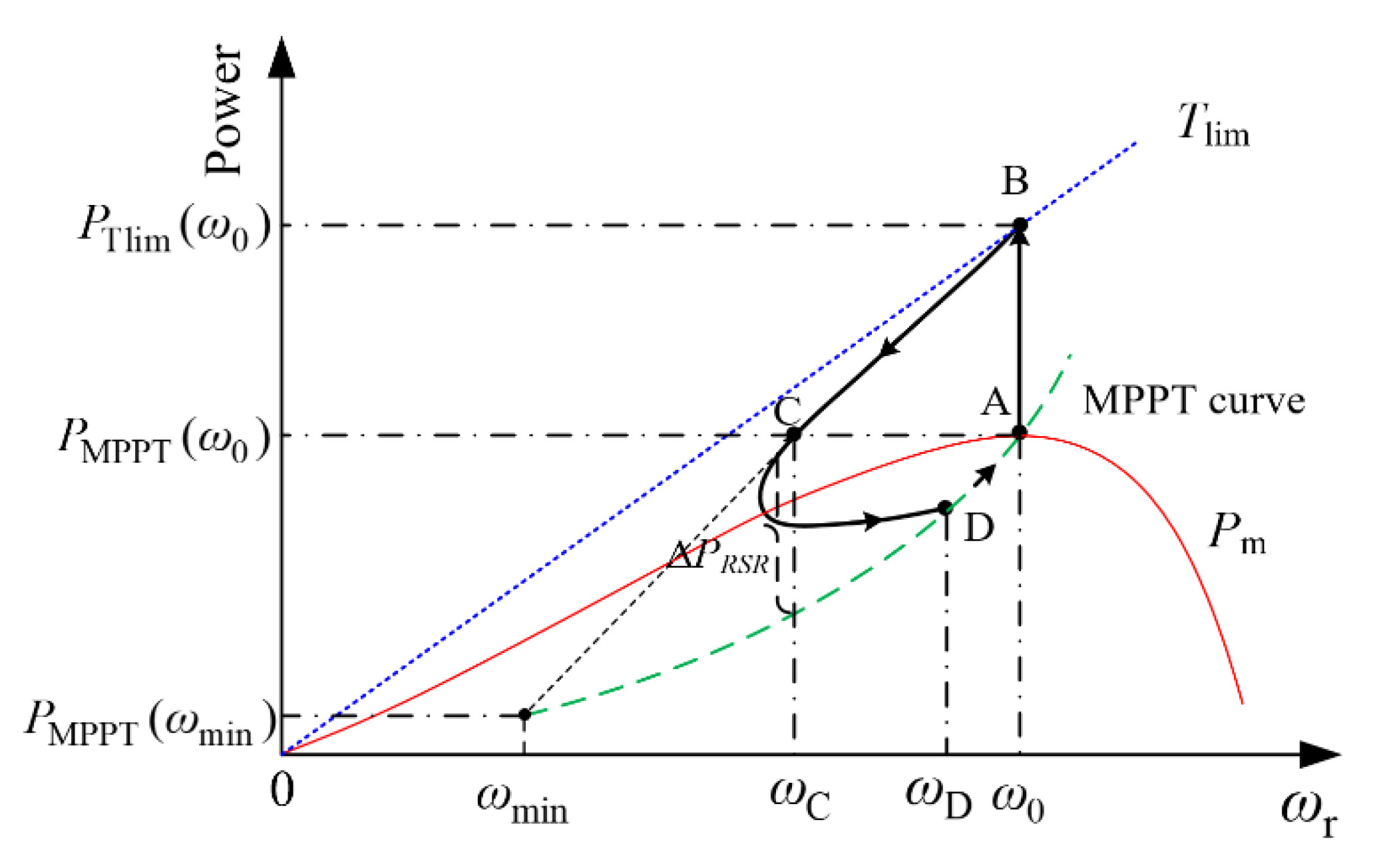
The control concept and characteristics of the proposed stepwise inertial control strategy are illustrated in Figure 3 and Figure 4, respectively. After detecting a frequency disturbance, the DFIG increases Pref to PB, corresponding to operating point B. Afterward, the DFIG decreases Pref using rotor speed to prevent the rotor from stalling, and the operating point moving from point B to point C. The power reference of the proposed stepwise inertial control scheme from operating point A to operating point C is the same as in (15). As a result, the proposed frequency support preserves the frequency nadir during the FSP.
In the RSRP (from operating point C to operating point D), the DFIG smoothly decreases the power reference based on the exponential function rather than instantly decreasing the correspondence with segment C-D in Figure 4. Therefore, the proposed stepwise inertial control scheme reduces the depth of the SFD and further reduces the wind turbine’s mechanical stresses. The power reference for RSRP is represented as:
where t1 is the instant of operating point C, ΔPRSR is the difference between Pset(ωC) and PMPPT(ωC), and α is the regulation factor of the RSRP.
The reasons why the RSRP initiates at operating point C is explained as follows: the system frequency is in the rebounding phase around operating point C. According to [1], the depth of the SFD reduces if the RSRP initiates during the frequency rebound phase. Thus, the expression of the suggested piecewise function during the FSP and RSRP is:
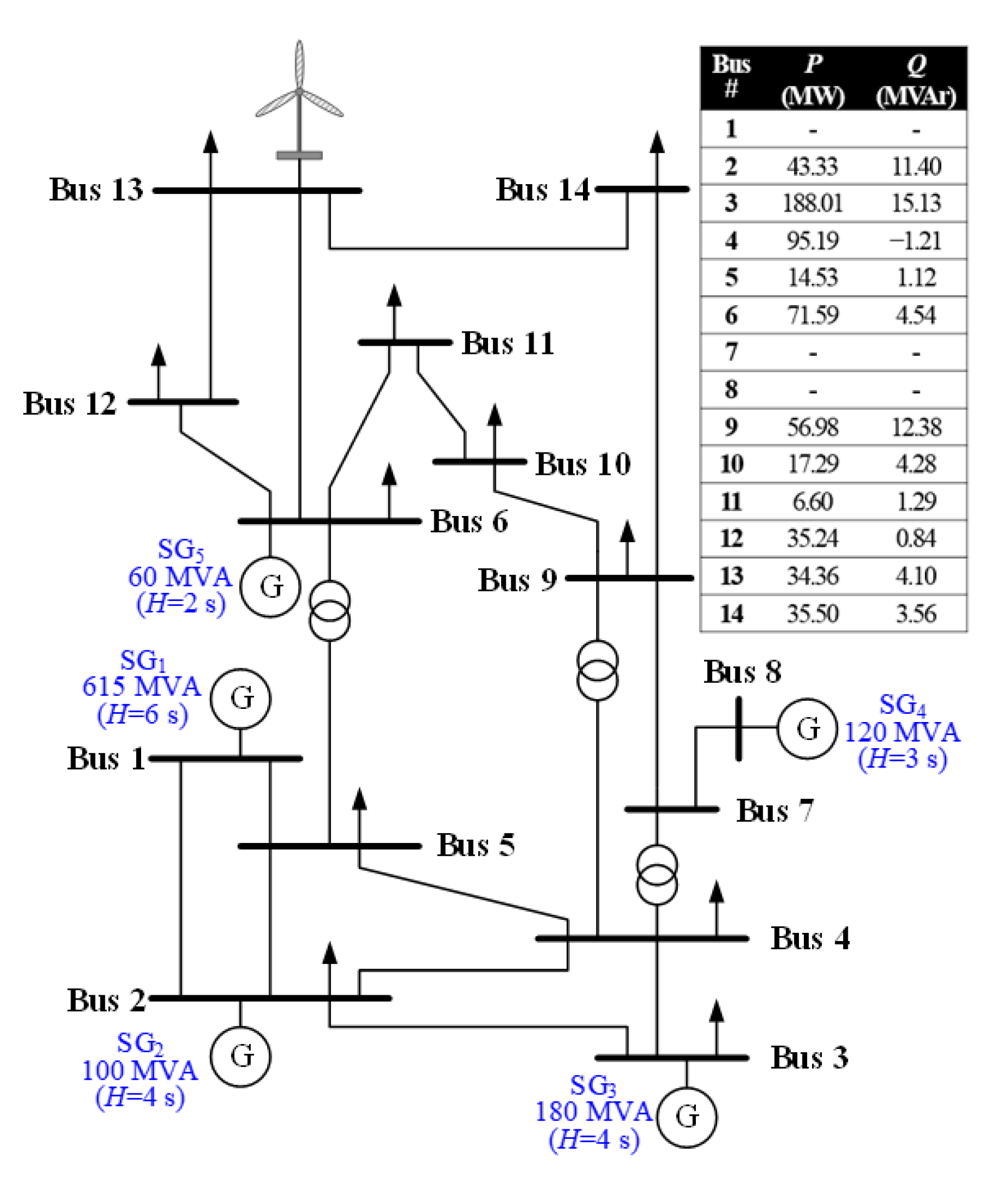
4. System Layout and Case Studies
To study the effectiveness of the proposed stepwise inertial control scheme, three cases with constant wind speed and ramp down wind speed conditions were conducted using the test system shown in Figure 5. The test system comprises five steam turbine synchronous generators, static loads and one DFIG-based wind farm. The capacities of steam turbine synchronous generators SG1, SG2, SG3, SG4, and SG5 are 615, 100, 180, 120, and 60 MVA, respectively. The settings of the inertia time constants for SG1, SG2, SG3, SG4, and SG5 are 6, 4, 4, 3, and 2 s, respectively. The parameters of the DFIG are shown in Table 1. The SG3, a disturbance that generates 150 MW, is tripped out.
The performance of the MPPT operation, conventional stepwise inertial control scheme, and proposed stepwise inertial control scheme was compared to study the performance of the dynamic frequency response, including the maximum frequency deviation, depth of the SFD, and torque difference between the high-speed shaft and low-speed shaft.
4.1. Case 1: Constant Wind Speed of 9.5 m/s, Wind Power Penetration of 15%
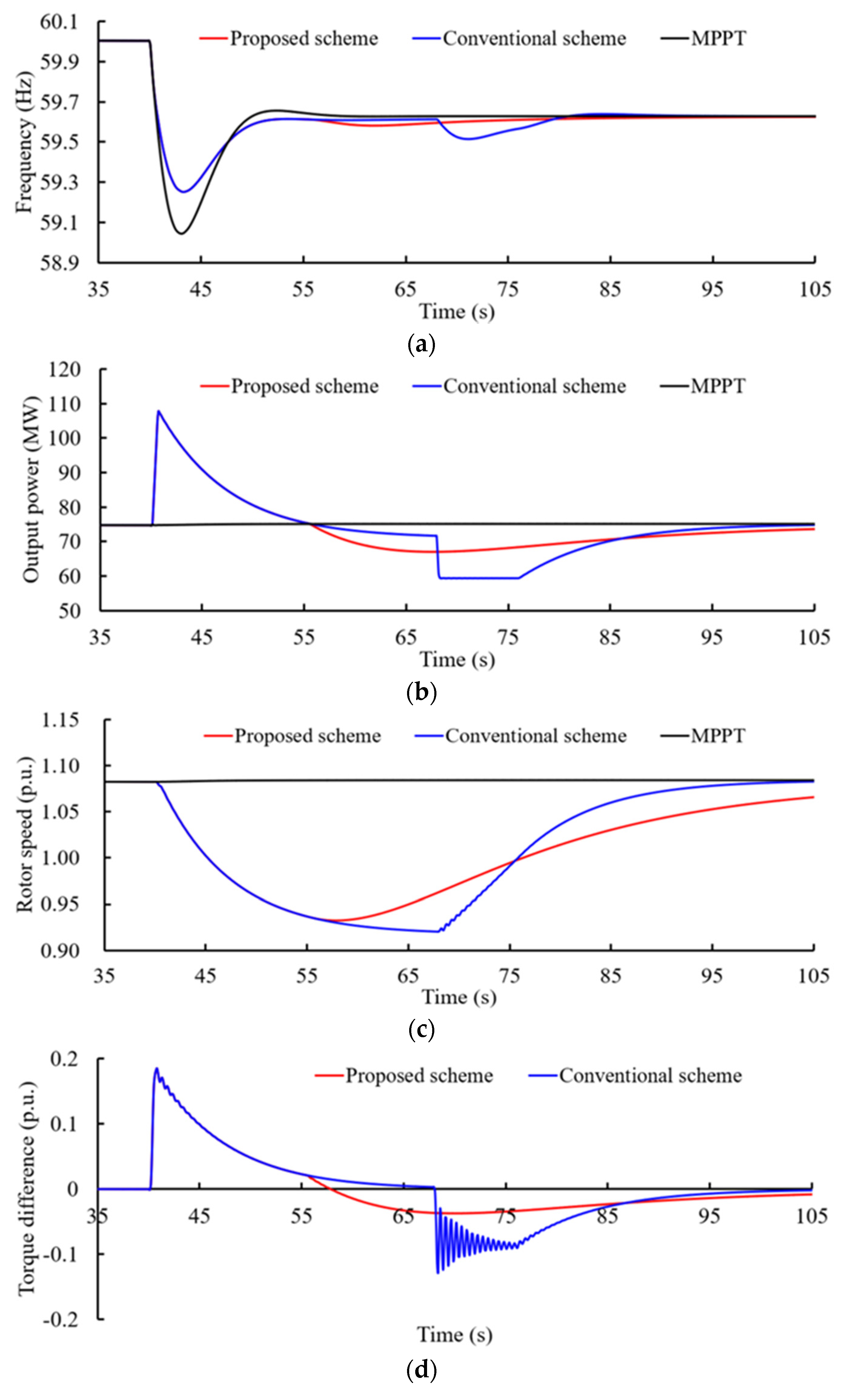
Figure 6 shows the grid frequency, output power of the DFIG, rotor speed, and torque difference between the low-speed shaft and high-speed shaft for Case 1. During the FSP, using the proposed stepwise inertial control and the conventional stepwise inertial control schemes reduces the maximum frequency deviation from 0.958 to 0.748 Hz. The reason for this phenomenon is that the proposed stepwise inertial control takes the same reference power function as the conventional scheme and the same injection of the active power prior at the beginning of a disturbance, as illustrated in Figure 6a,b.
As shown in Figure 6a,b, the depths of the SFD for the proposed and conventional stepwise inertial control schemes are 0.418 and 0.485 Hz, respectively; this is because during the RSRP, the use of the proposed stepwise inertial control strategy smoothly reduces the output power of the DFIG. In addition, the smooth decrease of the output is beneficial in reducing the wind turbine’s mechanical stress, as shown in Figure 6d. Furthermore, as shown in Figure 6c, the lowest rotor speeds of the proposed and conventional stepwise inertial control schemes are 0.936 and 0.922 pu, respectively. Therefore, using the proposed stepwise inertial control strategy releases less rotor energy compared with the conventional stepwise inertial control scheme during the FSP. Hence, using the proposed frequency scheme can preserve the frequency nadir while releasing less rotor energy.
4.2. Case 2: Constant Wind Speed of 9.5 m/s, Wind Power Penetration of 30%
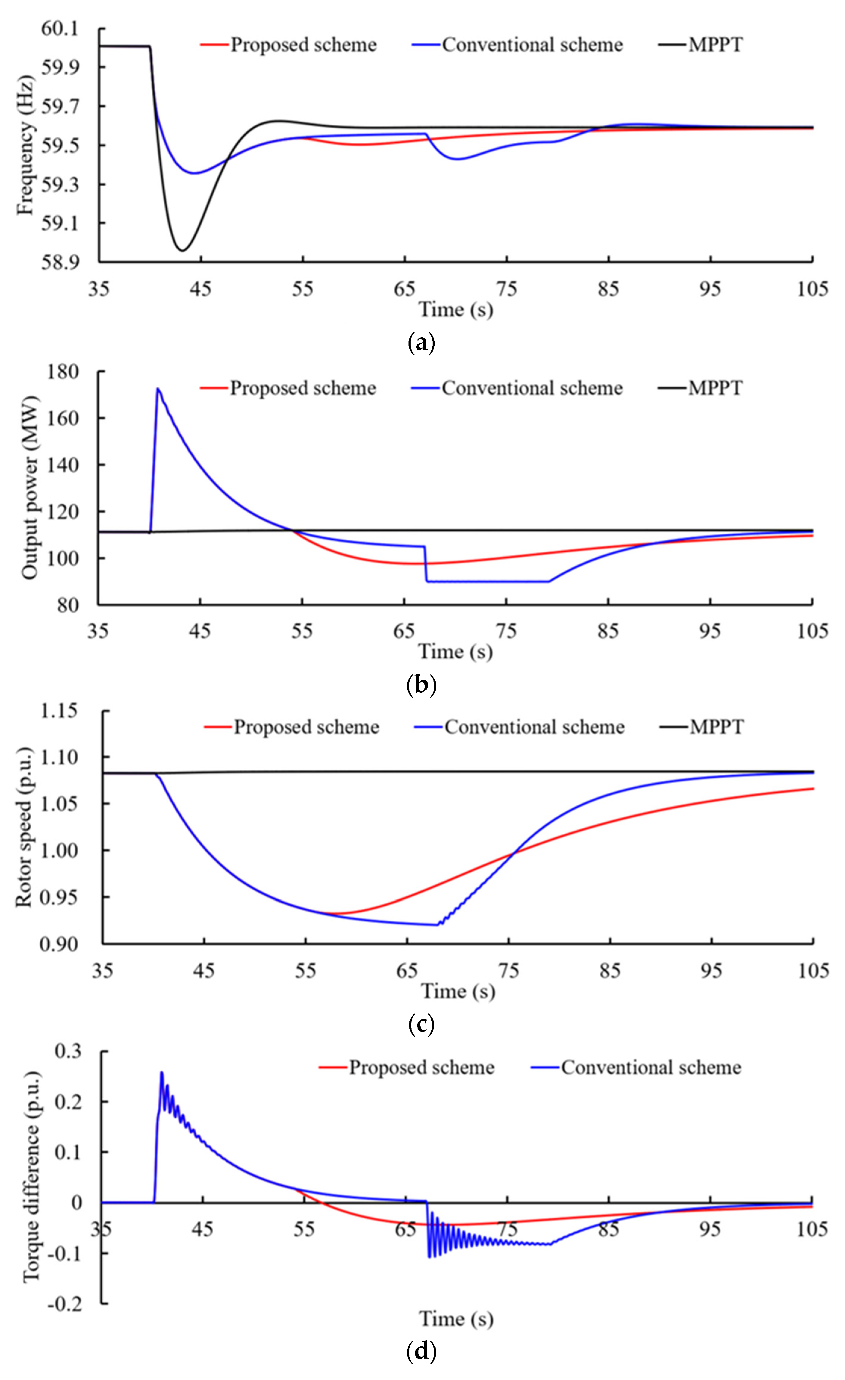
Figure 7 shows the grid frequency, output power of the DFIG, and rotor speed for Case 2. Table 2 shows the summary of Case 1 and Case 2.
The maximum deviation from the grid frequency of the MPPT operation is 1.043 Hz, which is more than a low wind penetration due to the reduced inertia and governor response of the SGs. As in Case 1, compared with MPPT, using the proposed stepwise inertial control and conventional stepwise inertial control schemes reduce the maximum frequency deviation by 0.411 Hz. Furthermore, as shown in Figure 7c, ωr in the proposed stepwise inertial control drops faster and decreases to 0.936 p.u. at 56.6 s, and then gradually returns to ω0; ωr in the conventional stepwise inertial control schemes converges to 0.922 p.u. at 66.9 s. Therefore, the proposed frequency support preserves the frequency stability with less rotor energy released from the DFIG and starts the rotor speed recovery earlier.
As shown in Figure 7a,b, the SFD size in the conventional stepwise inertial control scheme is 0.572 Hz which is more severe than a lower wind penetration and in the proposed stepwise inertial control scheme due to the large power reduction in MW. Moreover, the smooth decrease in the output helps to reduce the mechanical stress of the wind turbine, as shown in Figure 7d.
4.3. Case 3: Ramp down Wind Speed Conditions (Decreasing Wind Speeds from 9.5 to 7.0 m/s in 10 s)
The stalling of the wind turbine during the RSRP may be caused by ramp down wind speed conditions since the output power of the DFIG is higher than the changed mechanical input power. As a result, the rotor speed continues to decrease until the power reference descends to the MPPT curve. Thus, one scenario was used to investigate the influence of the ramp down wind speed conditions on the proposed and conventional stepwise inertial control schemes.
In this scenario, the ramp down wind speed decreases at 70.0 s from 9.5 to 7.0 m/s in 10.0 s. Before 70.0 s, the wind speed condition is the same as Case 1; thus, the maximum frequency deviation and released rotor energy are the same, as illustrated in Figure 8. After 70.0 s, during the RSRP, the use of the conventional scheme results in the stalling of the wind turbine because of the decreasing wind speed conditions. Consequently, the conventional scheme reduces the maximum frequency deviation to 59.259 Hz at 87.6 s. The proposed scheme decreases the active power output using the exponential function. Furthermore, the decreasing wind conditions cause an SFD of 59.468 Hz, which is almost the same as MPPT operation. Thus, the proposed scheme can prevent the wind turbine from stalling even under ramp down wind speed conditions.
5. Conclusions
In this article, we suggest a torque limit-based fast stepwise inertial control scheme of DFIGs to reduce the second frequency drop while preserving the FN with less rotor energy released using a piecewise reference function. The benefits of the optimized frequency support strategy were investigated using a test system embedded with DFIGs. The contribution of this strategy can be summarized as follows:
- During the FSP, this proposed FFR scheme preserves the FN with less rotor energy released. Thus, the proposed FFR scheme solves the issue that unnecessary rotor speed is released after rebounding the system frequency.
- During the RSRP, based on the second segment power reference function which is an exponential function in time domain, the output of the DFIG decreases smoothly and switches to MPPT without an active power mutation so as to realize the smooth rotor speed recovery and reduce the SFD. Thus, the proposed FFR scheme solves the issue of counterbalancing the performance for smoothing rotor speed recovery while reducing the mechanical stress on the wind turbines and reducing the SFD.
The simulation studies clearly indicate that the proposed FFR scheme preserves the frequency stability with less rotor energy released and reduces the second frequency drop and mechanical stress of wind turbines under scenarios of constant wind speeds, varying wind speeds, and various wind power penetrations.
For the future research, we plan to investigate the inertial control scheme of the DFIG using RTDS or RT-lab for hardware-in-the-loop simulations.
Author Contributions
Conceptualization, D.Y. and X.Z.; methodology, D.Y.; software, Y.X. and D.Y.; validation, Y.X., D.Y. and J.H.; formal analysis, L.H.; investigation, Y.X., D.Y. and X.Z.; resources, Y.X., D.Y. and J.H.; data curation, Y.X., D.Y. and X.Z.; writing-original draft preparation, Y.X. and D.Y.; writing-review and editing, All authors; visualization, L.H.; supervision, L.H.; funding acquisition, D.Y. and X.Z. All authors have read and agreed to the published version of the manuscript.
Funding
This work was supported by the Natural Science Foundation of the Jiangsu Higher Education Institutions of China (20KJB470026).
Institutional Review Board Statement
Not applicable.
Informed Consent Statement
Not applicable.
Data Availability Statement
Not applicable.
Conflicts of Interest
The authors declare no conflict of interest.
References
- Bao, W.; Ding, L.; Liu, Z.; Zhu, G.; Kheshti, M.; Wu, Q.; Terzija, V. Analytically derived fixed termination time for stepwise inertial control of wind turbines—Part I: Analytical derivation. Int. J. Elect. Power Energy Syst. 2020, 121, 106120. [Google Scholar] [CrossRef]
- Kabsha, M.M.; Rather, Z.H. A New Control Scheme for Fast Frequency Support From HVDC Connected Offshore Wind Farm in Low-Inertia System. IEEE Trans. Sustain. Energy 2020, 11, 1829–1837. [Google Scholar] [CrossRef]
- Lalor, G.; Ritchie, J.; Rourke, S.; Flynn, D.; O’Malley, M.J. Dynamic frequency control with increasing wind generation. IEEE Power Eng. Soc. Gen. Meet. 2004, 2, 1715–1720. [Google Scholar]
- Duval, J.; Meyer, B. Frequency behavior of grid with high penetration rate of wind generation. In Proceedings of the 2009 IEEE Bucharest PowerTech, Bucharest, Romania, 28 June–2 July 2009; pp. 1–6. [Google Scholar]
- Doherty, R.; Mullane, A.; Nolan, G.; Burke, D.J.; Bryson, A.; O’Malley, M. An Assessment of the Impact of Wind Generation on System Frequency Control. IEEE Trans. Power Syst. 2010, 25, 452–460. [Google Scholar] [CrossRef]
- Kerdphol, T.; Rahman, F.S.; Watanabe, M.; Mitani, Y. Robust Virtual Inertia Control of a Low Inertia Microgrid Considering Frequency Measurement Effects. IEEE Access 2019, 7, 57550–57560. [Google Scholar] [CrossRef]
- Garmroodi, M.; Verbič, G.; Hill, D.J. Frequency Support From Wind Turbine Generators With a Time-Variable Droop Characteristic. IEEE Trans. Sustain. Energy 2018, 9, 676–684. [Google Scholar] [CrossRef]
- Morren, J.; de Haan, S.W.H.; Ferreira, J.A. Contribution of DG units to primary frequency control. In Proceedings of the 2005 International Conference on Future Power Systems, Amsterdam, The Netherlands, 18–18 November 2005; p. 6. [Google Scholar]
- Kundur, P. Power System Stability and Control; China Electric Power Press: Beijing, China, 1994. [Google Scholar]
- Gevorgian, V.; Zhang, Y.; Ela, E. Investigating the impacts of wind generation participation in interconnection frequency response. IEEE Trans. Sustain. Energy 2015, 6, 1004–1012. [Google Scholar] [CrossRef]
- Kheshti, M.; Ding, L.; Bao, W.; Yin, M.; Wu, Q.; Terzija, V. Toward Intelligent Inertial Frequency Participation of Wind Farms for the Grid Frequency Control. IEEE Trans. Ind. Inf. 2020, 16, 6772–6786. [Google Scholar] [CrossRef]
- Attya, A.B.T.; Dominguez-García, J.L. Insights on the Provision of Frequency Support by Wind Power and the Impact on Energy Systems. IEEE Trans. Sustain. Energy 2018, 9, 719–728. [Google Scholar] [CrossRef] [Green Version]
- Tarnowski, G.C.; Kjar, P.C.; Sorensen, P.E.; Ostergaard, J. Variable speed wind turbines capability for temporary over-production. In Proceedings of the 2009 IEEE Power & Energy Society General Meeting, Calgary, AB, Canada, 26–30 July 2009; pp. 1–7. [Google Scholar]
- Mullane, A.; O’Malley, M. The inertial response of induction-machine-based wind turbines. IEEE Trans. Power Syst. 2005, 20, 1496–1503. [Google Scholar] [CrossRef]
- Lalor, G.; Mullane, A.; O’Malley, M. Frequency control and wind turbine technologies. IEEE Trans. Power Syst. 2005, 20, 1905–1913. [Google Scholar] [CrossRef]
- Morren, J.; de Haan, S.W.H.; Kling, W.L.; Ferreira, J.A. Wind turbines emulating inertia and supporting primary frequency control. IEEE Trans. Power Syst. 2006, 21, 433–434. [Google Scholar] [CrossRef]
- Ullah, N.R.; Thiringer, T.; Karlsson, D. Temporary Primary Frequency Control Support by Variable Speed Wind Turbines— Potential and Applications. IEEE Trans. Power Syst. 2008, 23, 601–612. [Google Scholar] [CrossRef]
- Mauricio, J.M.; Marano, A.; Gomez-Exposito, A.; Ramos, J.L.M. Frequency Regulation Contribution Through Variable-Speed Wind Energy Conversion Systems. IEEE Trans. Power Syst. 2009, 24, 173–180. [Google Scholar] [CrossRef]
- Loukarakis, E.; Margaris, I.; Moutis, P. Frequency control support and participation methods provided by wind generation. In Proceedings of the 2009 IEEE Electrical Power & Energy Conference (EPEC), Montreal, QC, Canada, 22–23 October 2009; pp. 1–6. [Google Scholar]
- Akbari, M.; Madani, S.M. Participation of DFIG based wind turbines in improving short term frequency regulation. In Proceedings of the 2010 18th Iranian Conference on Electrical Engineering, Isfahan, Iran, 11–13 May 2010; pp. 874–879. [Google Scholar]
- Tarnowski, G.C.; Kjær, P.C.; Dalsgaard, S.; Nyborg, A. Regulation and frequency response service capability of modern wind power plants. In Proceedings of the IEEE PES General Meeting, Minneapolis, MN, USA, 25–29 July 2010; pp. 1–8. [Google Scholar]
- Morren, J.; Pierik, J.; de Haan, S.W.H. Inertial response of variable speed wind turbines. Electr. Power Syst. Res. 2006, 76, 980–987. [Google Scholar] [CrossRef]
- Tarnowski, C.G. Wind Turbine Providing Grid Support. Patent WO2011000531A2, 6 January 2011. [Google Scholar]
- Ortiz, C.; Cruz, A.L.; Carrasco Solís, J.M.; Diez, E.G.; Franquelo, L.G. System for Using Energy Stored in the Mechanical Inertia of the Rotor of a Wind Turbine. Patent WO2003023224A1, 3 June 2003. [Google Scholar]
- Buendia, J. Wind Turbine Inertia Control System. Patent EP2918824A1, 16 September 2015. [Google Scholar]
- Burra, R.K.; Delmerico, R.W.; Bose, S.; Chandrashekhara, D.K. Multi-Use Energy Storage for Renewable Sources. U.S. Patent 20110074151A1, 31 March 2011. [Google Scholar]
- Arani, M.F.M.; Mohamed, Y.A.I. Dynamic Droop Control for Wind Turbines Participating in Primary Frequency Regulation in Microgrids. IEEE Trans. Smart Grid 2018, 9, 5742–5751. [Google Scholar] [CrossRef]
- Ravanji, M.H.; Cañizares, C.A.; Parniani, M. Modeling and Control of Variable Speed Wind Turbine Generators for Frequency Regulation. IEEE Trans. Sustain. Energy 2020, 11, 916–927. [Google Scholar] [CrossRef]
- Binbing, W.; Abuduwayiti, X.; Yuxi, C.; Yizhi, T. RoCoF Droop Control of PMSG-Based Wind Turbines for System Inertia Response Rapidly. IEEE Access 2020, 8, 181154–181162. [Google Scholar] [CrossRef]
- Ochoa, D.; Martinez, S. Fast-Frequency Response Provided by DFIG-Wind Turbines and its Impact on the Grid. IEEE Trans. Power Syst. 2017, 32, 4002–4011. [Google Scholar] [CrossRef]
- Yang, D.; Kim, J.; Kang, Y.C.; Muljadi, E.; Zhang, N.; Hong, J.; Song, S.H.; Zheng, T. Temporary frequency support of a DFIG for high wind power penetration. IEEE Trans. Power Syst. 2018, 33, 3428–3437. [Google Scholar] [CrossRef]
- Wang, S.; Tomsovic, K. Fast Frequency Support From Wind Turbine Generators With Auxiliary Dynamic Demand Control. IEEE Trans. Power Syst. 2019, 34, 3340–3348. [Google Scholar] [CrossRef]
- Hafiz, F.; Abdennour, A. Optimal use of kinetic energy for the inertial support from variable speed wind turbines. Renew. Energy 2015, 80, 629–643. [Google Scholar] [CrossRef]
- Kang, M.; Muljadi, E.; Hur, K.; Kang, Y.C. Stable adaptive inertial control of a doubly-fed induction generator. IEEE Trans. Smart Grid 2016, 7, 2971–2979. [Google Scholar] [CrossRef]
- Kang, M.; Kim, K.; Muljadi, E.; Park, J.W.; Kang, Y.C. Frequency control support of a doubly-fed induction generator based on the torque limit. IEEE Trans. Power Syst. 2016, 31, 4574–4583. [Google Scholar] [CrossRef]
- Xu, G.; Xu, L. Improved use of wind turbine kinetic energy for system frequency support. IET Renew. Power Gener. 2017, 11, 1094–1100. [Google Scholar] [CrossRef] [Green Version]
- Peng, X.; Yao, W.; Yan, C.; Wen, J.; Cheng, S. Two-Stage Variable Proportion Coefficient Based Frequency Support of Grid-Connected DFIG-WTs. IEEE Trans. Power Syst. 2020, 35, 962–974. [Google Scholar] [CrossRef]
- Miao, L.; Wen, J.; Xie, H.; Yue, C.; Lee, W.-J. Coordinate control strategy of wind turbine generator and energy storage equipment for frequency support. IEEE Trans. Ind. Appl. 2015, 51, 2732–2742. [Google Scholar] [CrossRef]
Figure 1.
Vector control of the rotor side converter.

Figure 2.
Operational features of the conventional scheme.

Figure 3.
Control concept of the proposed stepwise inertial control scheme.

Figure 4.
Operational features of the proposed stepwise inertial control scheme.

Figure 5.
Test system embedded with a DFIG.

Figure 6.
Results for Case 1: (a) frequency, (b) output power, (c) rotor speed, and (d) torque difference.
Figure 6.
Results for Case 1: (a) frequency, (b) output power, (c) rotor speed, and (d) torque difference.

Figure 7.
Results for Case 2: (a) frequency, (b) output power, (c) rotor speed, and (d) torque difference.
Figure 7.
Results for Case 2: (a) frequency, (b) output power, (c) rotor speed, and (d) torque difference.

Figure 8.
Results for Case 3: (a) wind speed, (b) frequency, (c) output power, and (d) rotor speed.


Table 1.
Parameters of the DFIG.
| Item | Values | Units |
|---|---|---|
| Nominal Stator Voltage | 2.3 | kV |
| Nominal Apparent Power | 5.5 | MVA |
| Nominal Active Power | 5.0 | MW |
| Magnetizing Reactance | 2.9 | p.u. |
| Stator Leakage Reactance | 0.18 | p.u. |
| Rotor Resistance | 0.016 | p.u. |
| Rotor Leakage Reactance | 0.16 | p.u. |
| Stator Resistance | 0.023 | p.u. |
| Inertia Constant | 5.0 | S |
| Stable Operating Range of ωr | 0.70–1.25 | p.u. |
| Rated, Cut-in, and Cut-out Speeds | 11, 4, and 25 | m/s |
| Based value of rotor speed | 235.62 | rad/s |
| Based value of torque | 21.78 | kNm |
Table 2.
Summary of Case 1 and Case 2.
| Scheme | Case 1 | Case 2 | |
|---|---|---|---|
| Frequency nadir (Hz) | MPPT | 59.042 | 58.957 |
| Conventional | 59.252 | 59.355 | |
| Proposed | 59.252 | 59.355 | |
| Second frequency drop (Hz) | MPPT | - | - |
| Conventional | 59.515 | 59.428 | |
| Proposed | 59.582 | 59.502 |
Publisher’s Note: MDPI stays neutral with regard to jurisdictional claims in published maps and institutional affiliations. |
© 2021 by the authors. Licensee MDPI, Basel, Switzerland. This article is an open access article distributed under the terms and conditions of the Creative Commons Attribution (CC BY) license (https://creativecommons.org/licenses/by/4.0/).
Share and Cite
MDPI and ACS Style
Xu, Y.; Yang, D.; Huang, J.; Zhang, X.; Hua, L. Fast Stepwise Inertial Control Scheme of a DFIG for Reducing Second Frequency Drop. Appl. Sci. 2021, 11, 8259. https://0-doi-org.brum.beds.ac.uk/10.3390/app11178259
AMA Style
Xu Y, Yang D, Huang J, Zhang X, Hua L. Fast Stepwise Inertial Control Scheme of a DFIG for Reducing Second Frequency Drop. Applied Sciences. 2021; 11(17):8259. https://0-doi-org.brum.beds.ac.uk/10.3390/app11178259
Chicago/Turabian StyleXu, Yien, Dejian Yang, Jiejie Huang, Xinsong Zhang, and Liang Hua. 2021. "Fast Stepwise Inertial Control Scheme of a DFIG for Reducing Second Frequency Drop" Applied Sciences 11, no. 17: 8259. https://0-doi-org.brum.beds.ac.uk/10.3390/app11178259
Note that from the first issue of 2016, this journal uses article numbers instead of page numbers. See further details here.