
Strain State in Metal Sheet Axisymmetric Stretching with Variable Initial Thickness: Numerical and Experimental Results


Dipartimento di Ingegneria Civile e Meccanica, Università degli Studi di Cassino e del Lazio Meridionale, 03043 Cassino, Italy
*
Author to whom correspondence should be addressed.
Appl. Sci. 2021, 11(17), 8265; https://0-doi-org.brum.beds.ac.uk/10.3390/app11178265
Submission received: 16 July 2021
/
Revised: 2 September 2021
/
Accepted: 3 September 2021
/
Published: 6 September 2021
(This article belongs to the Special Issue 10th Anniversary of Applied Sciences: Invited Papers in Mechanical Engineering Section)
Abstract
:Featured Application
This paper presents a stretching process of a metal sheet with a variable thickness. It gives products with better performances than that with constant thickness.
Abstract
This work presents a finite element model to analyze the distribution of the strains due to an axisymmetric stretching of a metal sheet. The sheet is characterized by a variable initial thickness. The resulting strain state is compared with that of a sheet with a constant initial thickness. The results of the present study allow asserting that the distribution of strains in the sheet can be controlled by setting opportunely the trend of the sheet initial thickness. In this way, it is possible to see that, starting from a sheet with variable initial thickness, a lighter final product is obtained, whose final thickness distribution is more uniform than that of the product obtained from a classic stretching process that requires a sheet with constant initial thickness. Encouraging results from an experimental activity carried out on an AA6060 aluminum alloy sheet, whose trend of initial thicknesses was prepared by removing material from a commercial sheet with a constant thickness, allow us to note the good agreement with what was theoretically highlighted.
1. Introduction
For several decades, to reduce the weight of the parts used in the transport sector and, therefore, the fuel needed to move them, steel parts have been replaced by light alloys based on aluminum or magnesium. The semi-finished product, in the form of sheet metal, is generally subjected to an ironing or drawing process both at room temperature (only aluminum alloy sheets) and hot (both aluminum alloy and magnesium alloy sheets). Conventional stretching processes at room temperature have two important drawbacks: light alloys are generally not easily formable and the thickness distribution produced is not uniform in the part subjected to deformation. 5xxx aluminum alloys have cold formability better than that of the 6xxx and 7xxx series alloys [1].
More generally, light alloys have reduced formability compared to steel and generate greater problems in terms of elastic return. To overcome, in part, the problem of failure of the sheet metal, in [2] it was proposed to operate properly on the force or pressure exerted on the blank holder. In [3,4], attention was paid to the flexibility of the dies and the adoption of an original blank holder.
However, to increase the formability of the material, reference is increasingly made to hot sheet metal working techniques.
In a review work on sheet metal working techniques [5], it was shown that a sheet can be heated directly or indirectly (by heating the equipment) and then subjected to the forming process.
In other cases, the sheet is pushed inside a die heated by the use of pressurized gas. In [6], a series of works related to materials and processing techniques of superplastic forming was collected. In [6,7], a complete overview of the quick plastic forming technology is presented.
To make the thickness distribution of a sheet metal component formed by a hot forming process as uniform as possible, in recent years, multiphase processes have been proposed. In [8], a two-stage superplastic forming process was designed and validated experimentally, while in [9], the thickness profile of a PbSn60 superplastic sheet metal component was optimized by adopting a two-phase gas forming process and making use of a fracture criterion during the design phase.
However, the hot working techniques present a series of drawbacks that are mainly related to the heating methods and, for some materials, to the reduction of the resistance properties.
Therefore, in [10,11] incremental sheet forming (ISF) and multi-point forming (MPF) were used as flexible forming processes to increase the formability of the material at room temperature. These processes are suitable to produce components of high value and belonging to small lots.
The ISF process allows reaching deformations deeper than the traditional forming process [12], while the main limit is represented by longer processing times. The MPF process makes it possible to obtain three-dimensional surfaces by adjusting the used punches [13]. The main limit is related to the presence of defects on the surface of the sheet due to the action of the punches. These defects were inevitable even in the presence of an elastic rubber sheet on the die surface [14]. Moreover, the size of the punches can limit the shape of the geometry of the workpiece to produce. To overcome the limits indicated above for flexible forming processes, in [15,16] processes have been proposed to be carried out in several forming steps. In [15], the sheet to be deformed is first subjected to an MPF process and then to an ISF process. In [16], a sheet pre-deformed by a process using a pressurized fluid is subsequently subjected to an ISF process.
For the sole purpose of standardizing the thickness of simple parts in superplastic material, in [17,18,19,20] methods to design the profile of the initial thicknesses of the sheet were proposed.
In this work, to optimize the final thickness distribution, the weight of the formed part, and to improve the formability of the material, a cold working technique is used which uses an initial plate characterized by a variable thickness profile. The sheet, clamped on a die in the peripheral region by a blank holder, is subjected to the action of a punch that stretches it inside the die.
The proposed process can produce an enlargement of the traditional classification of processes that make use of tailored blanks. Therefore, alongside the traditional classification [21] that distinguishes tailored blanks in tailor welded blanks, patchwork blanks, tailor rolled blanks and tailor heat treated blanks, it is possible to add tailored blanks based on removing material.
In [22], the reliability of the results due to a numerical simulation on industrial sheet metal forming cases was evaluated. The authors in [23] tested the use of numerical modeling based on the finite element method on a process for superplastic deformation of the sheet with excellent results and the forming limit diagram was analyzed in [24]. The finite element method is widely used in many fields [25,26].
The proposed paper presents a numerical model based on the finite element method to simulate an axisymmetric stretching of a metal sheet. The sheet is characterized by a variable initial thickness. The resulting strain state was compared with that of a sheet with a constant initial thickness. It was observed that starting from a sheet with variable initial thickness, a lighter final product is obtained, whose final distribution of thicknesses is more uniform than that of the product obtained from a classic stretching process that requires a sheet with constant initial thickness. Encouraging results from an experimental activity carried out on an AA6060 aluminum alloy sheet, whose trend of initial thicknesses was prepared by removing material from a commercial sheet with a constant thickness, allow to note the good agreement with what was theoretically highlighted. The proposed stretching process overcomes the state of the art since it involves processing times shorter than ISF and avoids defects on the surface of the sheet, such as MPF. Finally, it is easy to modify linearly the thickness of the blank using machining.
2. Materials and Methods
In this work, an axisymmetric process to stretch a metal sheet is studied through the MSC. Marc finite element software. In particular, as shown in Figure 1, a hemispherical punch characterized by a diameter of 120 mm, during its stroke, stretched a sheet positioned on a die (characterized by an inner diameter of 129.5 mm) and constrained to the edge from the presence of a blank holder (with a diameter of 166 mm) that avoided its slipping inside the die.
The problem being axisymmetric, four-noded isoparametric elements with bilinear interpolation were used. A comparison was presented between the use of axisymmetric elements and thick-shell elements to demonstrate that the best choice was the first one.
The sheet represented the deformable body and it was discretized using two rows of 166 elements. The mechanical behavior of the material was simulated through the use of a rigid–plastic model; therefore, the effects of the material spring-back phenomenon were neglected. The constitutive equation of the material is expressed by the following power law:
where σ and ε represent the equivalent stress and the equivalent strain respectively, while the strength coefficient K and the work-hardening index n are in constant connection with the material under study. The latter was represented by the aluminum-based alloy AA6060, whose chemical composition by weight was the following: Al-0.6% Si-0.3% Fe-0.1% Mn-0.6% Mg-0.1% Cu-0.15% Zn-0.05% Cr-0.1% Ti. The K and n constants of the material were derived from the results of the tensile tests: their values were equal to 135 MPa and 0.12 respectively.
σ = Kεn,
The punch and the die were considered rigid, while the blank holder was replaced by locking the displacement of the node, belonging to the outer edge of the sheet, into contact with the die. The other nodes of the outer edge, as well as the nodes of the sheet on the symmetry axis, were not able to move orthogonally to the axis of symmetry.
The simulation of the stretching process involved the contact between a deformable body and two rigid bodies. Furthermore, simulations were carried out in presence of friction among the bodies. Therefore, the appropriate contact option and the modified Coulomb friction model were used. Using these models, a relationship between the tangential ft and the normal fn forces was defined:
ft = μfn(2/π)arctg(vr/Rsv),
In this expression, vr represents the relative sliding speed and Rsv is the relative sliding speed value below which the friction force was null. The value of the friction coefficient μ was set equal to 0 in conditions of perfect lubrication, while the values 0,1 and 0.2 were taken into account in friction conditions, that are commonly used in sheet metal working processes.
The analysis of the results also foresees a comparison in conditions of sheet metal instability. This condition was defined by comparing the estimated strains during the process with the formability limit curve obtained from the local Hill theory [27] and the Swift diffusion theory [28].
Therefore, once β is defined as the ratio between the main strains, εmax and εmin, measured in the plane of the sheet, the formability limit parameter (FLP) is defined as:
where FLC (εmin) represents an analytical description of the formability limit curve. The expression assumed by the function FLC (εmin) for β ≤ 0 is:
while that for β > 0 is:
FLP = εmax/FLC(εmin)
In this way, FLP = 1 identifies the instant and the point in which the instability of the sheet happens during the deformation process.
3. Experimental Tests
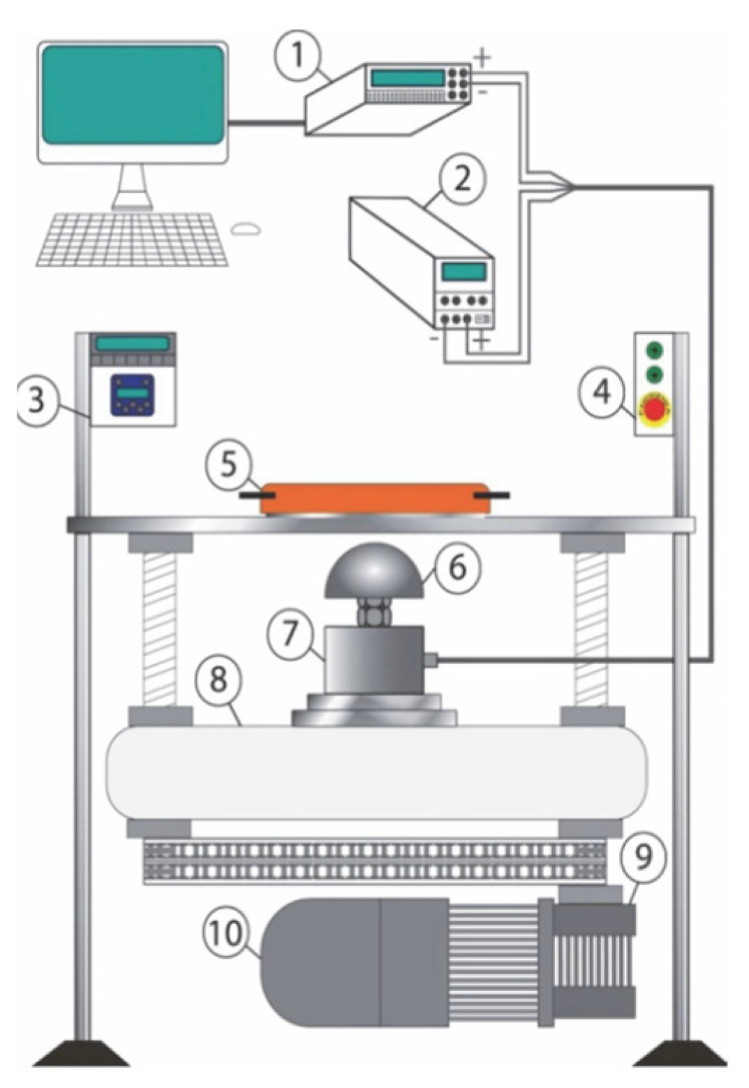
The experimental results of an axisymmetric stretching process were reported to have additional observations to support the theoretical study presented in the previous paragraph. The used metal sheet was made by an aluminum-based alloy AA6060. The stretching process was performed using a machine designed and built at the Laboratory of Technology and Manufacturing System of the University of Cassino and Southern Lazio, whose scheme is shown in Figure 2. It was constituted by a multimeter (1 in Figure 2) and a power supply (2 in Figure 2) connected to the load cell (7 in Figure 2) placed under the punch (6 in Figure 2) to measure the force trend applied by the punch on the sheet during the test. The vertical translation of the punch was due to a trapezoidal screw jack with an external female thread (9 in Figure 2), and an electric motor (10 in Figure 2) put into rotation the screw. The rotation of the screw generated an alternative straight upward or downward movement of the crosshead (8 in Figure 2) on which the punch coupled to a load cell was mounted. The sheet was fixed on the machine using the die-draw bead component (5 in Figure 2). Further details are reported in [29]. This machine allows (i) to perform forming tests with different values of the speed of the crossbar on which the punch is mounted and (ii) to monitor the force-stroke curve of the punch. The sheet was locked by the blank holder on a cylindrical die that has a hole of 129.50 mm diameter. A hemispherical steel punch characterized by a diameter of 120 mm pushed the sheet inside the die until a breaking line appeared on the extrados of the sheet itself. In this work, the results achieved in the absence of lubrication between the punch and the sheet are presented.
The stretch tests were carried out using both a constant initial thickness sheet equal to 1.03 mm and a sheet whose thickness varied from the edge to the pole, as shown in Figure 1. Concerning Figure 1, during the experimental tests, that were carried out with sheets of variable thickness, it was assumed that the thickness of the edge the was equal to 0.90 mm and the thickness of the pole thp was equal to 1.03 mm. The sheet with a variable initial thickness was produced, starting from a sheet with a constant initial thickness, by removing material according to the profile proposed in Figure 1. For each kind of sheet three replicas were carried out.
At the end of the test, it was possible to acquire the internal and external profile of the deformed sheet by a coordinate measuring machine. Therefore, it was possible to trace the thickness of the sheet and therefore the deformation along the thickness using an algorithm designed for this purpose [30]. In this way, it was possible to calculate the distribution of the deformation along with the thickness.
4. Results and Discussion
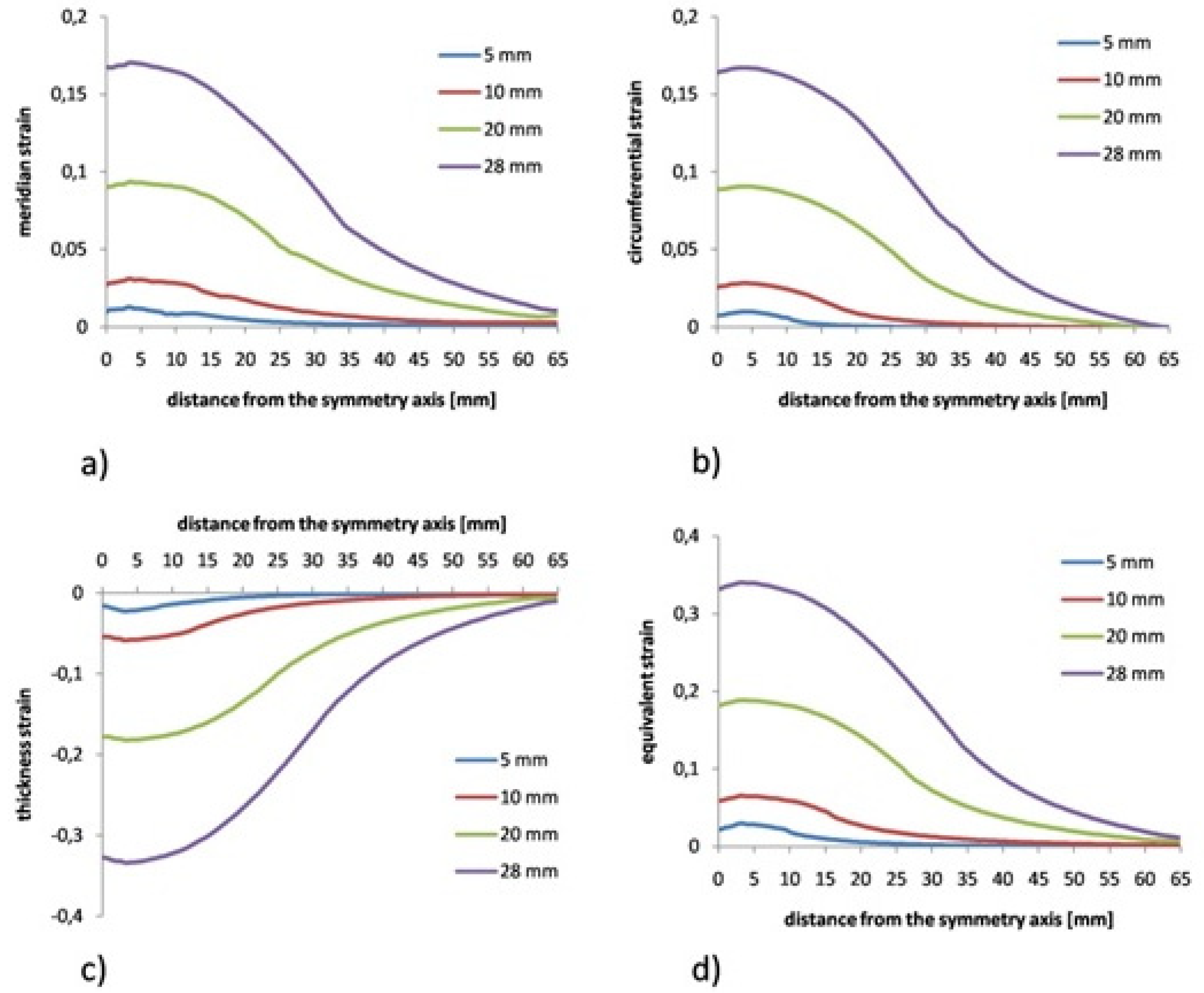
Figure 3, Figure 4 and Figure 5 show the strain on an AA6060 aluminum sheet with a constant initial thickness due to the FEM simulation of an axisymmetric stretching process.
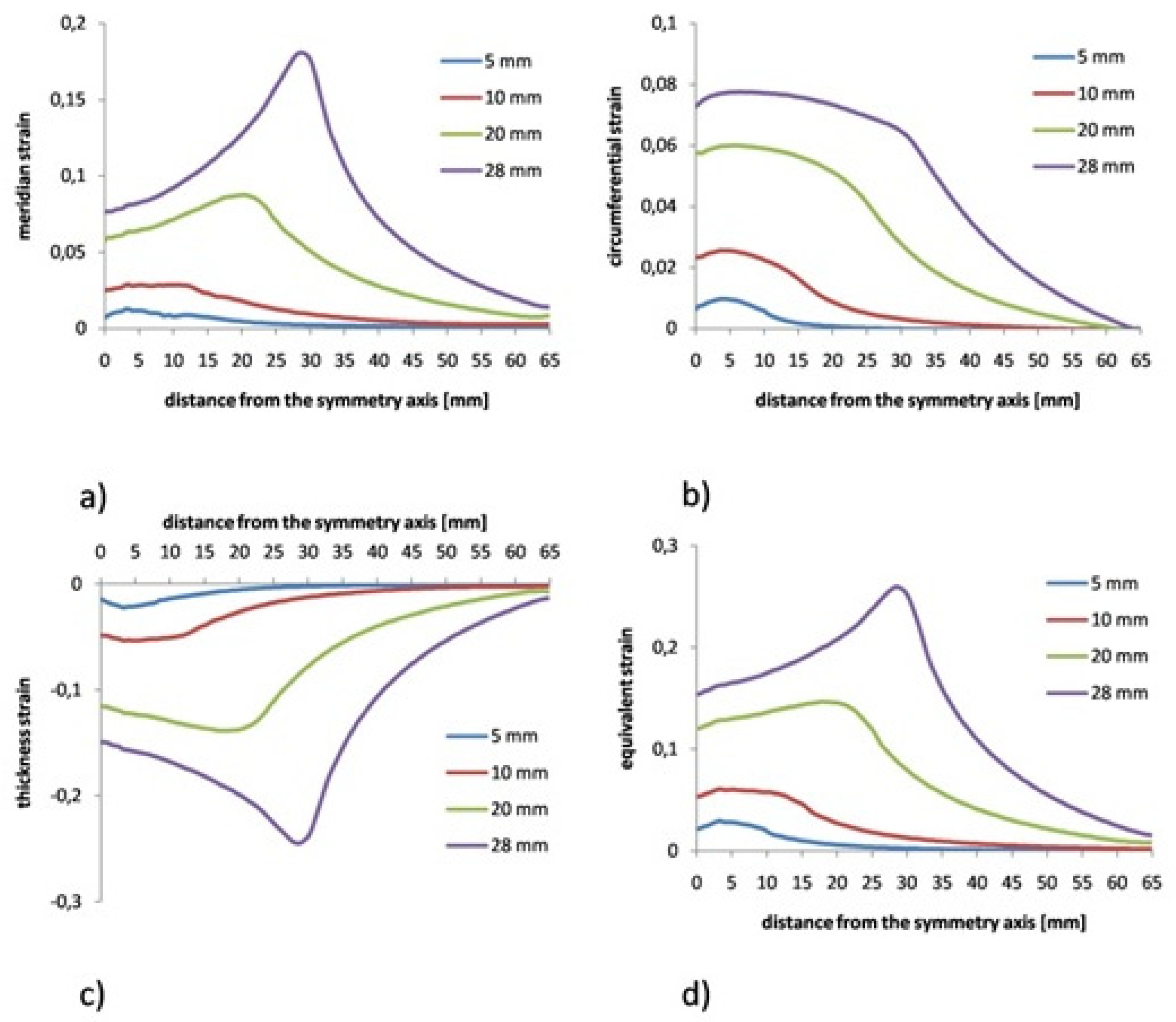
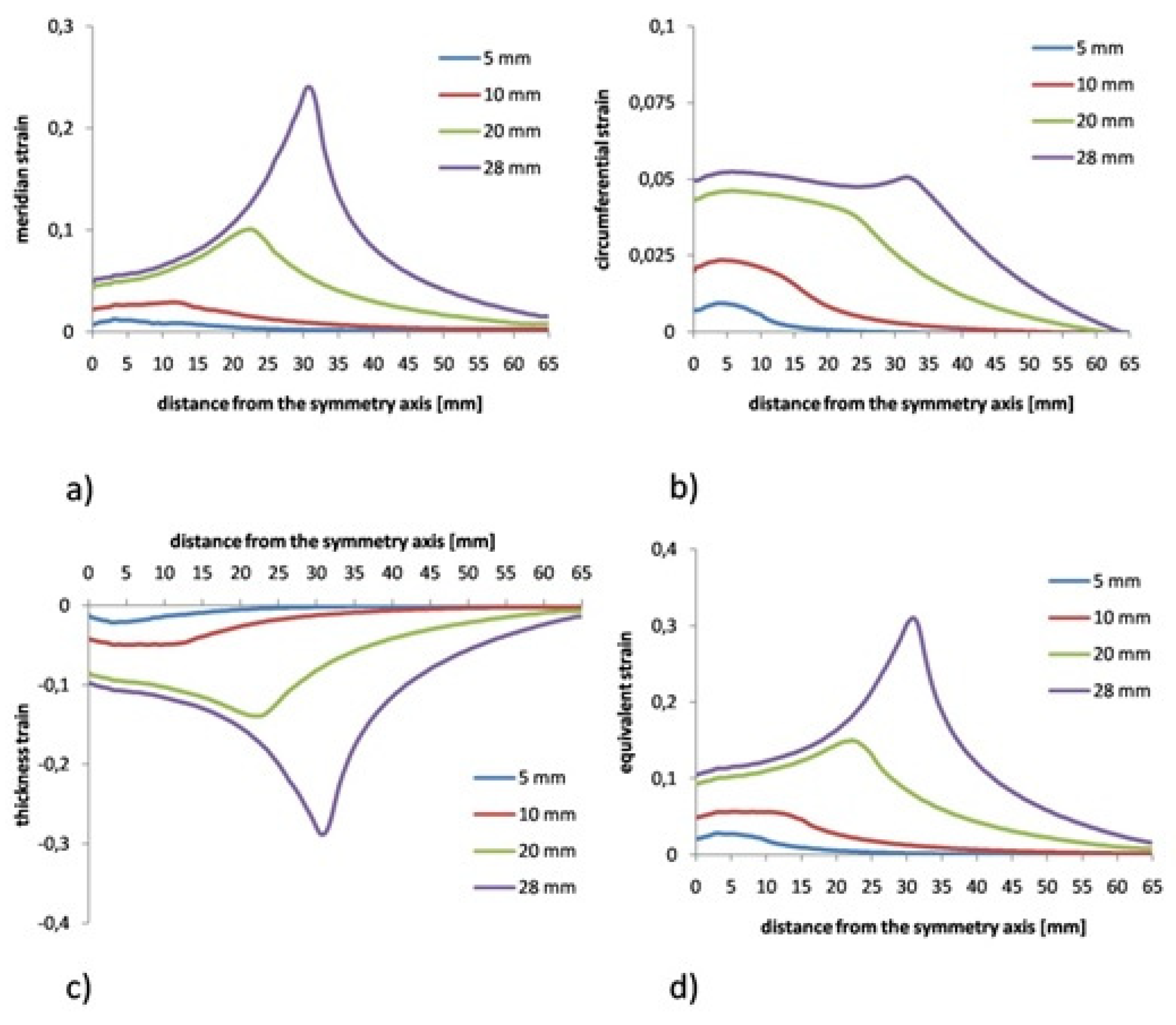
The figures are related to the results determined under conditions of perfect lubrication (Figure 3) and in presence of Coulomb friction (Figure 4 relates to the results achieved using a friction coefficient equal to 0.1, while Figure 5 concerns a friction coefficient equal to 0.2). In each figure, the distributions of the main strains (meridian, circumferential, and along with the sheet thickness) and the equivalent strain are represented versus the punch stroke. The strain distributions were connected with a punch stroke of 5, 10, 20, and 28 mm respectively. This last value (28 mm) represented the value of the stroke at break achieved during the experimental tests.
Figure 3 shows that, in conditions of perfect lubrication, the maximum strain was reached near the symmetry axis of the deformed part. On the contrary, increasing with the friction coefficient moved the maximum strain along with the sheet thickness (analogous to the equivalent strain) to a distance from the symmetry axis (see Figure 4 and Figure 5).
In this way, the failure due to thinning was determined in correspondence of an area where the contact between the punch and the sheet had not yet occurred. It should be noted that the strain along the thickness decreased quickly from the breaking point towards the edge of the sheet. This sheet area was therefore not subjected to deformation.
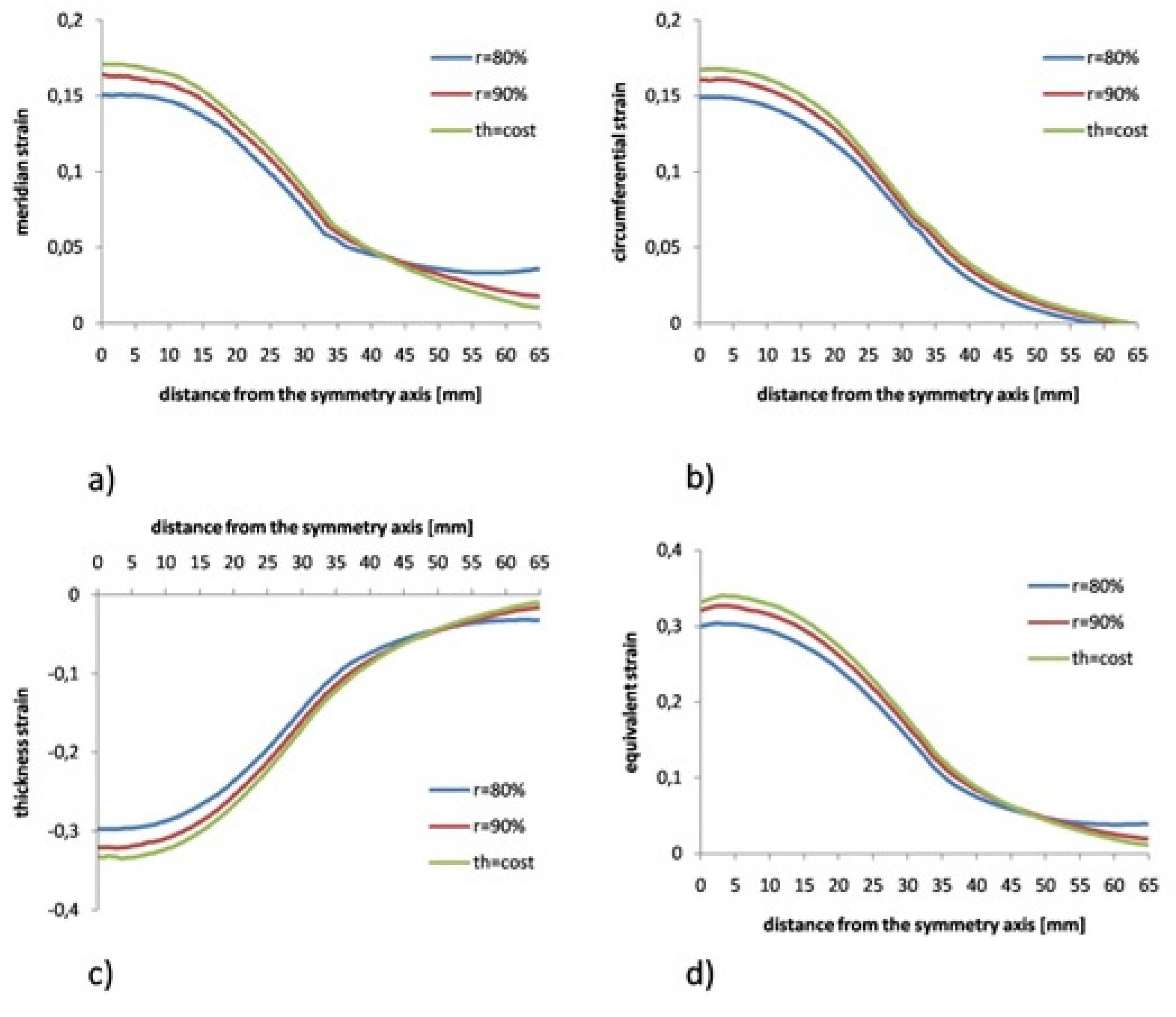
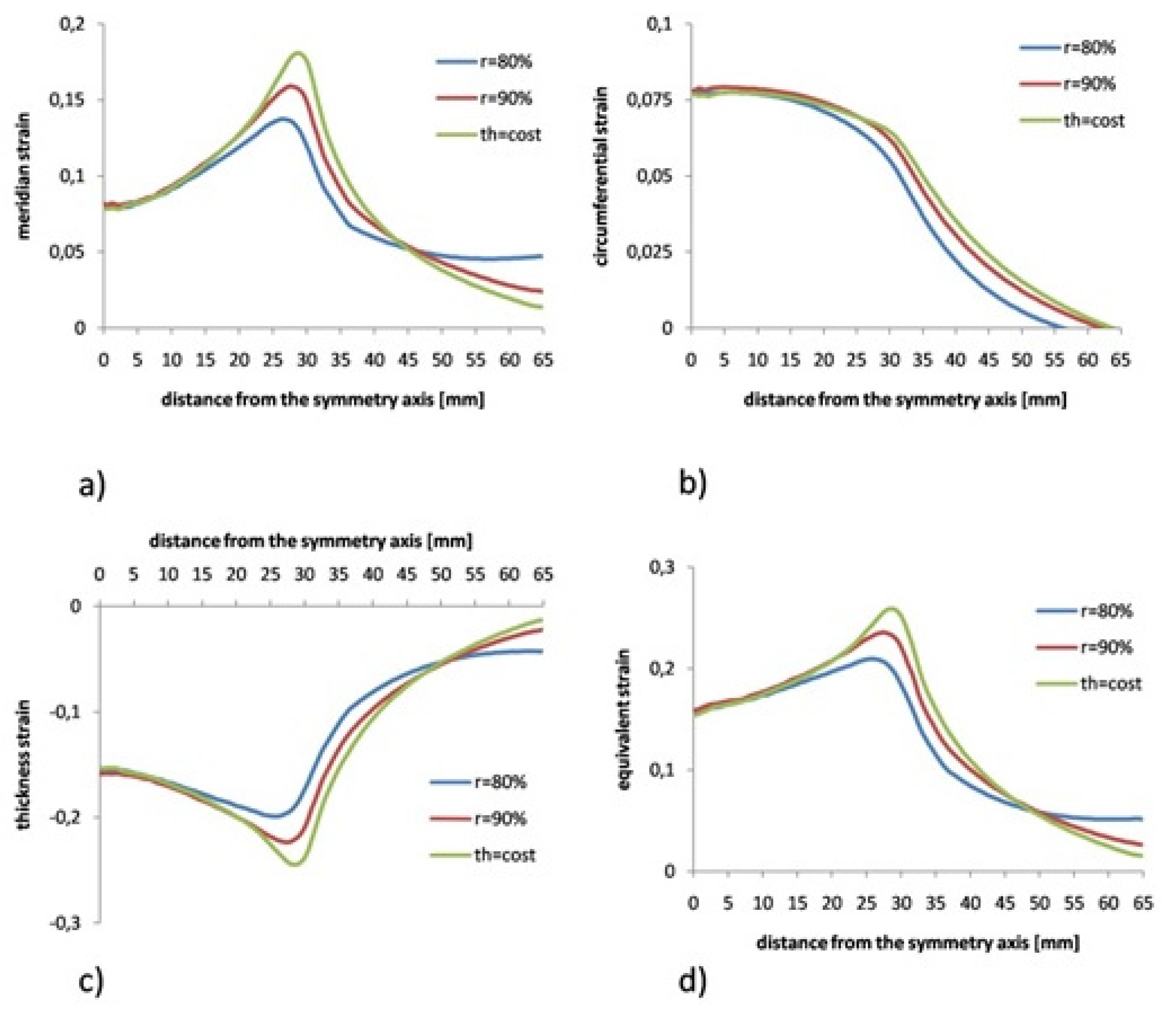
The axisymmetric stretching process was simulated by FEM too using sheets with a variable initial thickness as shown in Figure 1. The proposed thickness profile provided a reduction of the thickness towards the edge of the sheet, that is, in correspondence of that region of the sheet with a constant thickness that was little subjected to strain. Two cases were analyzed. The reduction of the thickness from the edge to the pole of the sheet (r = the/thp) was set equal to 90% and 80% respectively. In each case three friction conditions were analyzed, they were identified by a friction coefficient equal to 0 (perfect lubrication), 0.1, and 0.2. To explain as clearly as possible what happened during the stretching process, the results obtained under the most extreme deformation conditions, i.e., for a punch stroke of 28 mm, will be compared in the following. For each simulated friction condition, Figure 6, Figure 7 and Figure 8 show the comparison of the strain distribution, obtained with constant and variable thickness sheets and characterized by a 90% and an 80% reduction of the thickness from the edge to the sheet metal pole, r, respectively.
To analyze the obtained results, it is necessary to remember that, in conditions of constant volume, the strain modulus along the thickness is given by the sum of the meridian strain and the circumferential strain, which were the main strains performed in the plane of the sheet.
In presence of perfect lubrication, in the region of the sheet pole, the decrease of the thickness reduction r involved a decrease of both the meridian and the circumferential strain values with t more than it happened in a process carried out on a sheet with an initial constant thickness. Conversely, at the edge of the sheet, the decrease of the thickness reduction r involved an increase of the meridian strain. Composing these strains produced a strain along with the thickness (as well as an equivalent strain) that appeared more uniform than that due to a sheet with an initial constant thickness with the decrease of the thickness reduction r.
Some preliminary experimental results, carried out on the aluminum alloy AA6060, supported what was observed using finite element analysis. The experimental activity was performed using axial-symmetrical stretching tests at break using both constant thickness sheets and sheets characterized by a value of r = 0.87. No lubricant was used between the punch and the sheet. Therefore, the results obtained were to be considered in friction conditions.
Figure 9 shows the comparison between the strains measured along with the sheet thickness at the breaking point. The breaking point of the sheet with an initial variable thickness was reached for a punch stroke value higher by about 10% than that measured in a constant initial thickness test. The comparison of the results highlights greater formability and more uniform thickness distribution of the stretched sheet with an initial variable thickness than that with an initial constant thickness. Figure 9 experimentally confirms what was observed through FEM (see Figure 7c and Figure 8c). The observed trend was qualitatively identical.
5. Conclusions
In this work, the process of axisymmetric stretching on a metal sheet was analyzed and modeled by a numerical model. Through FEM analysis, the results of the process carried out using a sheet with an initial constant thickness were compared with those obtained starting from a sheet with an initial variable thickness.
The sheet stretched starting from an initial variable thickness is characterized by a thickness profile decreasing from the pole to the edge of the sheet. The ratio between the thickness at the edge and that at the pole is defined by the parameter r that was set equal to 90% and 80%. The results showed that the strain distribution is more uniform as r decreases. Those results were experimentally supported by tests on aluminum alloy plates AA6060. Moreover, the experimental results confirmed the trend obtained with FEM, i.e., the increase in formability of the sheet with an initial variable thickness.
The obtained results are useful for the automotive and transport industry, where increasingly lighter and formed parts are sought.
Further studies are focused on a sensitivity analysis of the proposed stretching process by varying the values of forming parameters that were kept constant in this paper, such as the friction coefficient.
Author Contributions
Conceptualization, G.G. and W.P.; methodology, G.G.; software, G.G.; validation, W.P.; formal analysis, G.G.; investigation, W.P.; resources, G.G. and W.P.; data curation, W.P.; writing—original draft preparation, G.G.; writing—review and editing, W.P. All authors have read and agreed to the published version of the manuscript.
Funding
This research received no external funding.
Institutional Review Board Statement
Not applicable.
Informed Consent Statement
Not applicable.
Conflicts of Interest
The authors declare no conflict of interest.
References
- Sotirov, N.; Falkinger, G.; Grabner, F.; Schmid, G.; Schneider, R.; Grant, R.J.; Kelsch, R.; Radlmayr, K.; Scheerer, M.; Reichl, C.; et al. Improved formability of AA5182 aluminium alloy sheet at cryogenic temperatures. Mater. Today Proc. 2015, 2, S113–S118. [Google Scholar] [CrossRef]
- Ahmetoglu, M.A.; Altan, T.; Kinzel, G.L. Improvement of part quality in stamping by controlling blank-holder force and pressure. J. Mater. Process. Technol. 1992, 33, 195–214. [Google Scholar] [CrossRef]
- Doege, E.; Elend, L.E. Design and application of pliable blank holder systems for the optimization of process conditions in sheet metal forming. J. Mater. Process. Technol. 2001, 111, 182–187. [Google Scholar] [CrossRef]
- Cao, J.; Kinsey, B.L.; Yao, H.; Viswanathan, V.; Song, N. Next generation stamping dies–controllability and flexibility. Robot. Comput.-Integr. Manuf. 2001, 17, 49–56. [Google Scholar] [CrossRef]
- Zheng, K.; Politis, D.J.; Wang, L.; Lin, J. A review on forming techniques for manufacturing lightweight complex-shaped aluminium panel components. Int. J. Light. Mater. Manuf. 2018, 1, 55–80. [Google Scholar] [CrossRef]
- Giuliano, G. Superplastic Forming of Advanced Metallic Materials: Methods and Applications; Woodhead Publishing Ltd.: Cambridge, UK, 2011; pp. 1–369. [Google Scholar]
- Krajewski, P.E.; Schroth, J.G. Overview of quick plastic forming technology. Mater. Sci. Forum 2007, 551–552, 3–12. [Google Scholar] [CrossRef]
- Luckey, G.; Friedman, P.; Weinmann, K. Design and experimental validation of a two-stage superplastic forming die. J. Mater. Process. Technol. 2009, 209, 2152–2160. [Google Scholar] [CrossRef]
- Giuliano, G.; Corrado, A.; Polini, W. Influence of multiphase forming approach on the thickness uniformity of components from superplastic PbSn60 alloy. Manuf. Lett. 2018, 18, 16–19. [Google Scholar] [CrossRef]
- Matsubara, S. Incremental backward bulge forming of a sheet metal with a hemispherical tool. J. Jpn. Soc. Technol. Plast. 1994, 35, 1311–1316. [Google Scholar]
- Liu, C.; Li, M.; Fu, W. Principles and apparatus of multipoint forming for sheet metal. Int. J. Adv. Manuf. Technol. 2008, 35, 1227–1233. [Google Scholar] [CrossRef]
- Jeswiet, J.; Young, D. Forming limit diagrams for single-point incremental forming of aluminium sheet. Proc. Inst. Mech. Eng. Part B J. Eng. Manuf. 2005, 219, 359–364. [Google Scholar] [CrossRef]
- Li, M.Z.; Cai, Z.Y.; Sui, Z.; Yan, Q.G. Multi-point forming technology for sheet metal. J. Mater. Process. Technol. 2002, 129, 333–338. [Google Scholar] [CrossRef]
- Wang, Z.R.; Yuan, S.J. New forming technologies used in manufacturing large vessels. Int. J. Mach. Tools Manuf. 2006, 46, 1180–1187. [Google Scholar] [CrossRef]
- Lu, B.; Zhang, H.; Xu, D.K.; Chen, J. A hybrid flexible sheet forming approach towards uniform thickness distribution. Procedia CIRP 2014, 18, 244–249. [Google Scholar] [CrossRef] [Green Version]
- Shamsari, M.; Mirnia, M.J.; Elyasi, M.; Baseri, H. Formability improvement in single point incremental forming of truncated cone using a two-stage hybrid deformation strategy. Int. J. Adv. Manuf. Technol. 2018, 94, 2357–2368. [Google Scholar] [CrossRef]
- Akkus, N.; Suzuki, K.; Kawahara, M.; Nishimura, H. Influence of performing on the final thickness distribution of the superplastically deformed domes. Mater. Sci. Forum 1999, 304–306, 759–764. [Google Scholar] [CrossRef]
- Kim, Y.H.; Lee, J.-M.; Hong, S.S. Optimal design of superplastic forming processes. J. Mater. Process. Technol. 2001, 112, 166–173. [Google Scholar] [CrossRef]
- Huang, A.; Lowe, A.; Cardew-Hill, M.J. Experimental validation of sheet thickness optimization for superplastic forming of engineering structures. J. Mater. Process. Technol. 2001, 112, 136–143. [Google Scholar] [CrossRef]
- Dutta, A. Thickness-profiling of initial blank for superplastic forming of uniformly thick domes. Mater. Sci. Eng. A 2004, 371, 79–81. [Google Scholar] [CrossRef]
- Merklein, M.; Johannes, M.; Lechner, M.; Kuppert, A. A review on tailored blanks—Production, applications and evaluation. J. Mater. Process. Technol. 2014, 214, 151–164. [Google Scholar] [CrossRef]
- Gantar, G.; Pepelnjak, T.; Kuzman, K. Optimization of sheet metal forming processes by the use of numerical simulations. J. Mater. Process. Technol. 2002, 130–131, 54–59. [Google Scholar] [CrossRef]
- Giuliano, G. Constitutive Modelling of Superplastic AA-5083. Tech. Mech. 2012, 32, 221–226. [Google Scholar]
- Giuliano, G. Analysis of Forming Limit Diagram for Superplastic Materials. Int. J. Adv. Manuf. Technol. 2006, 31, 244–246. [Google Scholar] [CrossRef]
- Ali, B.; Nie, Y.; Hussain, S.; Habib, D.; Abdal, S. Insight into the dynamics of fluid conveying tiny particles over a rotating surface subject to Cattaneo–Christov heat transfer, Coriolis force, and Arrhenius activation energy. Comput. Math. Appl. 2021, 93, 130–143. [Google Scholar] [CrossRef]
- Ali, B.; Pattnaik, P.K.; Naqvi, R.A.; Waqas, H.; Hussain, S. Brownian motion and thermophoresis effects on bioconvection of rotating Maxwell nanofluid over a Riga plate with Arrhenius activation energy and Cattaneo-Christov heat flux theory. Therm. Sci. Eng. Prog. 2021, 23, 100863. [Google Scholar] [CrossRef]
- Hill, R. On discontinuous plastic states with special reference to localized necking in thin sheets. J. Mech. Phys. Solids 1952, 1, 19–30. [Google Scholar] [CrossRef]
- Swift, H.W. Plastic instability under plane stress. J. Mech. Phys. Solids 1952, 1, 1–18. [Google Scholar] [CrossRef]
- Giovinco, G.; Giuliano, G.; Testa, G. Forming apparatus to investigate the effect of temperature on the superplastic behaviour of alloys. AIP Conf. Proc. 2010, 1252, 304–311. [Google Scholar]
- Giuliano, G.; Corrado, A.; Polini, W. A geometric algorithm to evaluate thickness distribution of stretched sheets through finite element analysis. Appl. Sci. 2021, 11, 1905. [Google Scholar] [CrossRef]
Figure 1.
Scheme of the axisymmetric stretching on a sheet with an initial variable thickness (1 is the punch, 2 is the blank and 3 is the die).
Figure 1.
Scheme of the axisymmetric stretching on a sheet with an initial variable thickness (1 is the punch, 2 is the blank and 3 is the die).

Figure 2.
Machine used for the forming tests: ➀ multimeter; ➁ power supply; ➂ interface for the test parameters management; ➃ control panel for the punch translation; ➄ die-drawbead component; ➅ punch; ➆ load cell; ➇ crosshead; ➈ rotating screw jack; ➉ electric motor.
Figure 2.
Machine used for the forming tests: ➀ multimeter; ➁ power supply; ➂ interface for the test parameters management; ➃ control panel for the punch translation; ➄ die-drawbead component; ➅ punch; ➆ load cell; ➇ crosshead; ➈ rotating screw jack; ➉ electric motor.

Figure 3.
Distribution of the main strains and equivalent strain during the stretching process in perfect lubrification condition due to FEM: (a) meridian strain; (b) circumferential strain; (c) thickness strain; (d) equivalent strain.
Figure 3.
Distribution of the main strains and equivalent strain during the stretching process in perfect lubrification condition due to FEM: (a) meridian strain; (b) circumferential strain; (c) thickness strain; (d) equivalent strain.

Figure 4.
Distribution of the main strains and equivalent strain during the stretching process in friction conditions with a friction coefficient μ = 0.1 due to FEM: (a) meridian strain; (b) circumferential strain; (c) thickness strain; (d) equivalent strain.
Figure 4.
Distribution of the main strains and equivalent strain during the stretching process in friction conditions with a friction coefficient μ = 0.1 due to FEM: (a) meridian strain; (b) circumferential strain; (c) thickness strain; (d) equivalent strain.

Figure 5.
Distribution of the main strains and equivalent strain during the stretching process in friction conditions with a friction coefficient μ = 0.2 due to FEM: (a) meridian strain; (b) circumferential strain; (c) thickness strain; (d) equivalent strain.
Figure 5.
Distribution of the main strains and equivalent strain during the stretching process in friction conditions with a friction coefficient μ = 0.2 due to FEM: (a) meridian strain; (b) circumferential strain; (c) thickness strain; (d) equivalent strain.

Figure 6.
Comparison between the main strains and the equivalent strain during the stretching process on a constant (th = cost) and a variable (r = 80% e r = 90%) thickness sheet in perfect lubrification condition due to FEM: (a) meridian strain; (b) circumferential strain; (c) thickness strain; (d) equivalent strain.

Figure 7.
Comparison between the main strains and the equivalent strain during the stretching process on a constant (th = cost) and a variable (r = 80% e r = 90%) thickness sheet in friction conditions with a friction coefficient μ = 0.1 due to FEM: (a) meridian strain; (b) circumferential strain; (c) thickness strain; (d) equivalent strain.

Figure 8.
Comparison between the main strains and the equivalent strain during the stretching process on a constant (th = cost) and a variable (r = 80% e r = 90%) thickness sheet in friction conditions with a friction coefficient μ = 0.2 due to FEM: (a) meridian strain; (b) circumferential strain; (c) thickness strain; (d) equivalent strain.

Figure 9.
Comparison between experimental results in terms of thickness strain due to a stretching process on a sheet with an initial constant thickness and an initial variable thickness.
Figure 9.
Comparison between experimental results in terms of thickness strain due to a stretching process on a sheet with an initial constant thickness and an initial variable thickness.

Publisher’s Note: MDPI stays neutral with regard to jurisdictional claims in published maps and institutional affiliations. |
© 2021 by the authors. Licensee MDPI, Basel, Switzerland. This article is an open access article distributed under the terms and conditions of the Creative Commons Attribution (CC BY) license (https://creativecommons.org/licenses/by/4.0/).
Share and Cite
MDPI and ACS Style
Giuliano, G.; Polini, W. Strain State in Metal Sheet Axisymmetric Stretching with Variable Initial Thickness: Numerical and Experimental Results. Appl. Sci. 2021, 11, 8265. https://0-doi-org.brum.beds.ac.uk/10.3390/app11178265
AMA Style
Giuliano G, Polini W. Strain State in Metal Sheet Axisymmetric Stretching with Variable Initial Thickness: Numerical and Experimental Results. Applied Sciences. 2021; 11(17):8265. https://0-doi-org.brum.beds.ac.uk/10.3390/app11178265
Chicago/Turabian StyleGiuliano, Gillo, and Wilma Polini. 2021. "Strain State in Metal Sheet Axisymmetric Stretching with Variable Initial Thickness: Numerical and Experimental Results" Applied Sciences 11, no. 17: 8265. https://0-doi-org.brum.beds.ac.uk/10.3390/app11178265
Note that from the first issue of 2016, this journal uses article numbers instead of page numbers. See further details here.