
Can ISO GPS and ASME Tolerancing Systems Define the Same Functional Requirements?


Institute of Machine Design Fundamentals, Warsaw University of Technology, 00-661 Warsaw, Poland
Appl. Sci. 2021, 11(17), 8269; https://0-doi-org.brum.beds.ac.uk/10.3390/app11178269
Submission received: 20 July 2021
/
Revised: 19 August 2021
/
Accepted: 28 August 2021
/
Published: 6 September 2021
(This article belongs to the Special Issue New Trends in Manufacturing Metrology)
Abstract
:Geometrical tolerances are defined in the ISO Geometrical Product Specification system that is used worldwide, but on the other hand, the ASME Y14.5 standard is used in American companies to define how far actual parts may be away from their nominal geometry. This paper aimed to investigate whether specifications defining acceptable geometrical deviations in one system can be transformed to specifications in the other system. Twelve selected cases are discussed in the paper. Particularly, two cases of size tolerance, three cases of form tolerances, one case of orientation tolerance, four cases of position tolerance (including position tolerance with MMR for the pattern of five holes) and, finally, two cases of surface profile tolerance (unequally disposed tolerance zone and dynamic profile tolerance). The issue is not only in the several different symbols and a set of different defaults, but also in the different meanings and different application contexts of some symbols that have the same graphical form. The answer to the question raised in the paper title is yes for the majority of indications specified according to ASME Y14.5 when new tools from the 2017 edition of ISO 1101 are applied.
1. Introduction
Manufacturing metrology covers verification of whether produced parts fulfil functional requirements defined by a customer. A designer transforms functional requirements into dimensional and geometrical tolerances that limit actual part deviations and determine a part’s performance [1,2]. For example, roundness deviations and dimensional deviations of bearings and their adjacent components (shaft and housing) determine a cylindrical roller bearing’s vibrational behaviour and fatigue life [3]. Assemblability of additive manufactured metal parts also depends largely on the size, flatness, cylindricity, perpendicularity and position tolerances of a part’s geometrical features, along with their deviations [4].
The geometrical product specification and verification system developed in ISO by Technical Committee ISO/TC 213 (ISO GPS system) [5] is a set of concepts, principles, rules and symbols that enable description and clarification of how far geometrical features of an actual workpiece can be away from theoretically exact geometry (CAD model of a part) [6,7,8,9,10,11]. The international standards that constitute the ISO GPS system are implemented as national standards in countries all over the world and are widely used in local and international companies. The foundation of geometrical specifications for the ISO GPS system are provided in ISO 1011 [12] and other International Standards give more detail [7,8,9,10]. On the other hand, the US National Standard ASME Y14.5-2018 [13] also establishes uniform practices for stating and interpreting geometrical requirements. ASME Y14.5 is globally used because many USA companies locate their branches or look for suppliers in emerging countries that have lower labour costs. Both the ISO GPS system standards and ASME Y14.5 secure functional tolerancing and intend to provide uniformity in drawing specifications and interpretation. Some companies selected ASME Y14.5 much before American companies started de-centralizing manufacturing from the USA to other countries, because nearly all of the info is in one document that is focused on design intent and there is the opinion that it is easier to understand [14].
Specification of functional requirements according to ASME Y14.5-2018 is quite often called geometric dimensioning and tolerancing, shortly referred to by the acronym GD&T. To improve the usability of ASME Y14.5-2018, the revised standard ASME Y14.5.1-2019 [15], which establishes the uniform mathematical basis for interpreting dimensional and geometrical tolerances, has been published.
Nowadays, due to globalization, many suppliers face a challenge to work with two systems in parallel due to their customer requirements or supplier experience and capability. The ASME and ISO standards have many similarities in indications and definitions but in some aspects they are different. A careful comparison of ASME Y14.5 and the ISO GPS system tolerance indications enabled us to distinguish four cases:
- Interpretation of the same symbols is always the same;
- Interpretation of the same symbols in certain cases is the same;
- Interpretation of the same symbols is never the same—the same symbols are intended to be used in different contexts;
- Some symbols (indications) are available only in one system.
There are a few papers that have addressed the differences between the ISO GPS system and ASME Y14.5 [16,17]. In Appendix C to ASME Y14.5-2018, two tables are given to compare the symbols used in ASME Y14.5 with symbols available in the ISO GPS system. It is worth mentioning that in the opposite relation of comparison i.e., aiming to show how many symbols and modifiers defined in the ISO GPS system are available in ASME Y14.5-2018 standard, there would be a lot of comments not available in the ASME column. The tables given in ASME Y14.5-2018 indicate only if the same symbols are available in the ISO GPS system without any information as to whether the identical graphical symbol has the same meaning. At the end of Section 2 of this paper, a comparison table that provides much more detail is given. Some differences between ASME Y14.5 and ISO 1101 are also shown in [18], but it shall be underlined that the latest editions of both standards, which are considered in this paper, are not compared in [18].
In both systems, there are several different default rules i.e., specification and interpretation rules that are not stated by particular indications in the drawings but are only enforced due to the selection of a particular tolerancing system that is indicated in the drawing title block. In both systems, specifications by tolerance zone and specifications by gauge are available. Specification by gauge is functionally oriented to assembly and enables the use of virtual boundaries that may be implemented by material (physical) or virtual (digital) gauges to examine a part’s ability to mate with its respective counterpart.
It is the task of each designer to determine the permissible size, form, orientation and location deviations, which, if not violated, allow an intended performance of a part. The aim of this paper was to investigate how tolerances may be allocated (specified) in both systems to secure identical permissible deviations of manufactured parts from their nominal geometrical models. There are two important cases:
- Local design office (familiar with one system) has to develop a product for a global company working with another system;
- Local supplier working with one tolerancing system is forced to adopt technical product documentation from a global company prepared according to another tolerancing system.
In both cases, the objective is to secure a part function. Below several specifications made according to ASME Y14.5 will be “translated” to specifications made according to the ISO GPS system notations. It should be noted that transformation from ASME Y14.5 to the ISO GPS notation without loss of the part’s intended function (loss of coded information) may be performed in a significantly larger amount of cases than reverse conversion due to a new set of modifiers implemented in ISO 1101:2017 [7]. It was underlined in [2] that ISO 1101:2017 allows for more precise tolerance definitions that are independent of the view plane and also support digital threads for geometry assurance. One hundred and fifty ISO documents [5] currently form the ISO GPS system, but only about ten devoted to geometrical tolerancing are directly addressed to designers, manufacturers and quality staff involved in product development and production. They will be analyzed in this paper to find the ISO GPS system specifications that are equivalent to specifications given according to ASME Y14.5.
The issue of changing specifications of geometrical tolerances indicated according to ASME Y14.5 to the ISO GPS system is important for industry. The survey results on the usage of ISO GPS and ASME Y14.5 standards shows that 20% of companies will, in the future, use both ASME Y14.5 and the ISO GPS system standards [14].
The role of tolerance information sharing through a product life cycle was carefully analysed in [19], with good remarks on the capability of computer-aided design tools. Particularly, it was stated that currently available CAD systems only partly support rule-based tolerance specifications and processing of tolerancing information is performed with many manual interventions. Most advanced CAD systems allow for checking, taking into account the particular tolerance system [19]. Currently, a user can select the ISO GPS system or ASME Y14.5 standard, but switching from one tolerance system to another will not update specified tolerance indications according to the selected system. Further development of the commercial software is required to automate such a transition.
2. From ASME Y14.5 Specifications to the ISO GPS System Drawing
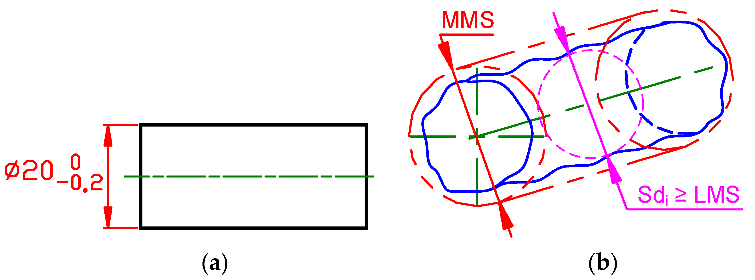
Dimensioning and tolerancing should clearly define a designer’s intent [20]. All dimensions and tolerances should be selected and specified to secure the functional requirements and mating relationship of a part, and should not allow more than one interpretation. The coupling of the shafts and holes requires the appropriate actual geometry of mating parts. The default Rule #1 in ASME Y14.5 establishes the condition that allows parts to fit every time. According to Rule #1, unless otherwise specified, the limits of the size of an individual feature of size control the form of the feature as well as the size (Figure 1). It means, functionally, that even at maximum shaft and minimum hole diameters, the shaft will be able to freely pass through the mating hole if it is required by a designer. The surface of a shaft shall not extend beyond the boundary (envelope) of the perfect form at maximum material condition. The maximum material size is equal to MMS = 20 mm. The actual local size is defined by a continuously expanding and contracting sphere pulled through the shaft. To meet the local size requirements, the minimum local sphere (LMS = 19.8 mm) shall never exit the material.
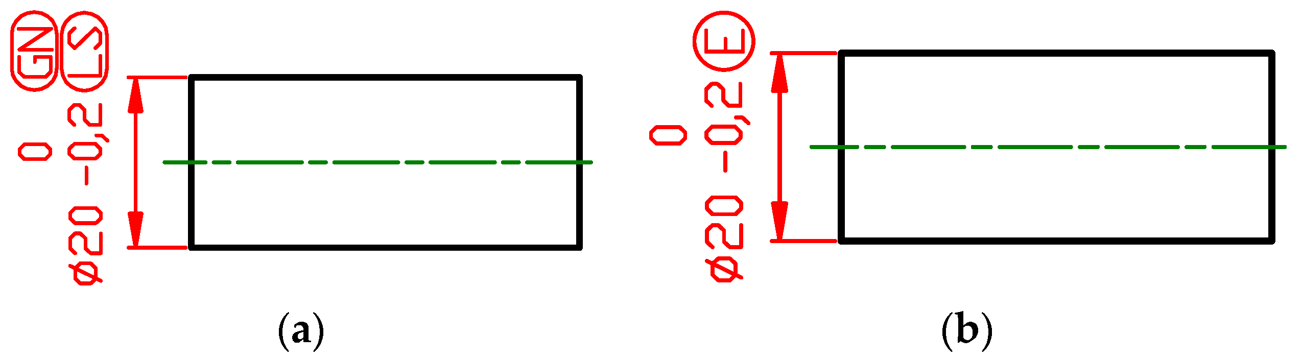
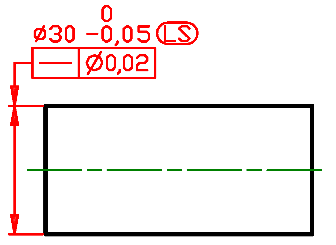
To find the equivalent specification according to the ISO GPS system notation, it is necessary to start with an explanation (Figure 1b)—two requirements are established: minimum circumscribed size (global size) [21] is equal to 20 mm and spherical size (local size) is equal 19.8 mm. In Figure 2a, the upper limit size is 20 mm due to the modifier minimum circumscribed size (letters GN placed in the elongated circle) and the lower limit size is 19.8 mm due to the modifier local size defined by a sphere (letters LS placed in in the elongated circle). Both sizes are defined exactly as ASME Y14.5 default size. It is difficult to verify the local size defined by a sphere, so in most cases, for the lower limit of size 19.8 mm, a two-point size is applied and the specification given in Figure 2b is regarded as equivalent to ASME Y14.5 default size defined according to Rule #1. Dimensional evaluation algorithms for a feature of size according to ASME Y14.5 and the ISO GPS system specifications are discussed in [22].
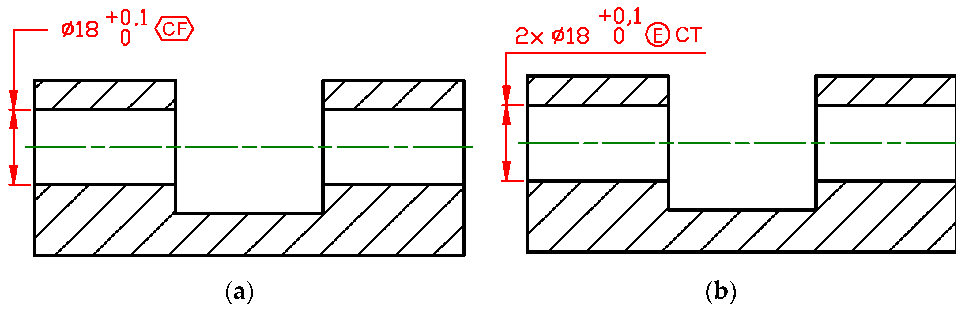
The term continuous feature of size, designated with the “CF” symbol, is used in ASME Y14.5 (Figure 3a) to indicate that one or more interrupted features shall be considered as a single feature of size. It means that no portion of the continuous feature crated by two holes shall extend inside one envelope of perfect form at maximum material condition, MMC, (MMS = 18 mm). Almost the same (see Figure 2 for slight difference) functional requirement is controlled in the ISO GPS system by indication CT [21], which stands for common tolerance feature of size (Figure 3b).
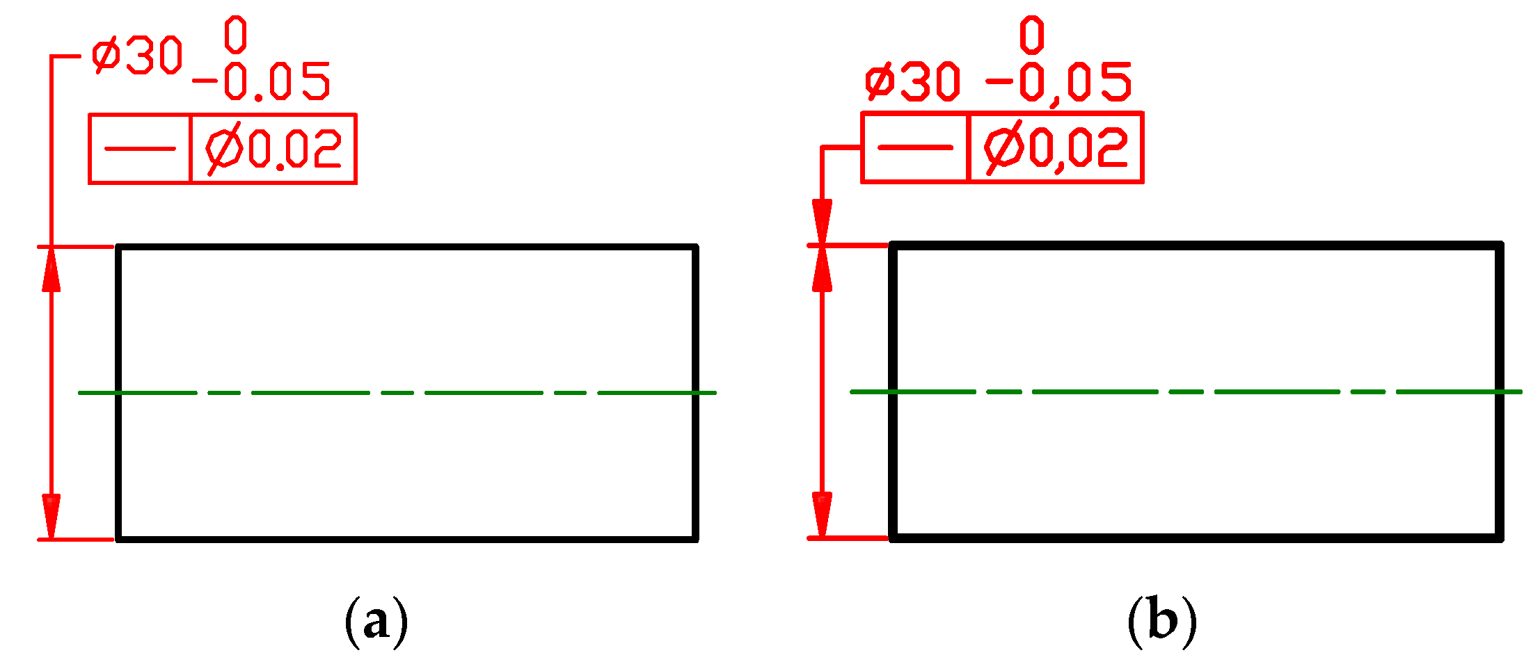
When ASME Y14.5 feature control frame with the straightness symbol is attached to an extension of the dimension line of a cylindrical feature (Figure 4a), the default Rule #1 is cancelled and the size of the shaft shall be verified as local size defined by continuously expanding and contracting spheres. According to the independency principle formulated in ISO 8015 [23], by default, every GPS specification for a feature or relation between features shall be fulfilled independently of other specifications, except when a modifier that overrules the independency principle is stated. So, by default, the size in Figure 4b is considered as the two-point size and the straightness tolerance applies to the derived median line. The two-point size is a distance between two opposite points of the shaft’s extracted surface, where the connection line between the points includes the associated least square circle centre and the cross-sections are perpendicular to the axis of the associated least square cylinder obtained from the shaft’s extracted surface [24]. Specifications in Figure 4a,b seem to be identical, but the default interpretation of the local size is different in ASME Y14.5 and in the ISO GPS system. The equivalent specifications are shown in Figure 5.
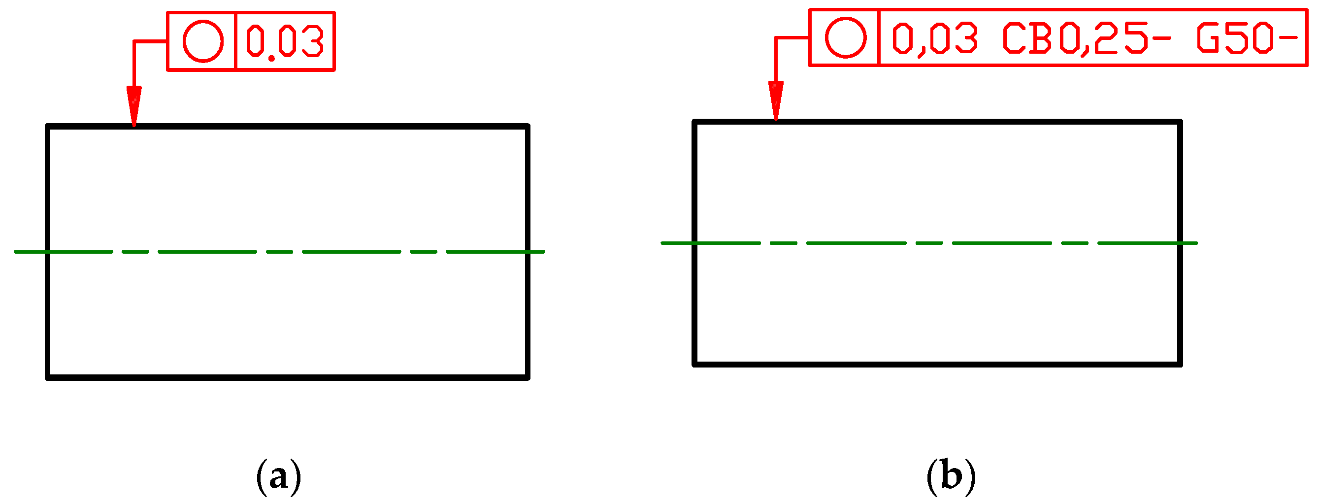
The circularity (roundness) tolerance specified in Figure 6a is listed in ASME Y14.5 as the form tolerance, and in ANSI B89.3.1 [25], further information is given. ANSI/ASME B89.3.1 states, by default (i.e., without any additional symbols), that for roundness measurement, the following conditions apply: reference method, MRS (minimum radial separation); filter, 50 UPR (undulation per revolution); and tip radius, 0.25 mm. Currently, default measuring conditions for roundness tolerance are not specified in the ISO GPS system standards, but ISO 1101 [12] provides symbols that a designer may use to set up measuring conditions (Figure 6b). The specification element CB indicates that a closing ball filter is specified. The value “0.25” indicates that a 0.25 mm radius ball shall be used as the structuring element and, because it is followed by “-”, it is a long-wave pass filter, which removes short wavelengths. The closing ball filter may be physically implemented as the diameter of the ball stylus tip. The specification element G indicates that a Gaussian filter is specified with nesting index 50 UPR. Due to the fact that the value “50” is followed by “-”, it is a long-wave pass filter, which removes short wavelengths (higher UPR values). The specification, therefore, applies to a feature (circumferential line) that has been digitally filtered with a 50 UPR Gaussian long-wave pass filter. By default, each individual filtered circumferential line shall be contained in a tolerance zone defined as the space between two concentric circles with the 0.03 mm radius difference. It is worth mentioning that in American Standards, default conditions are only specified for roundness deviation measurement. The default conditions for measurement of other form deviations (cylindricity, flatness and straightness) are not given.
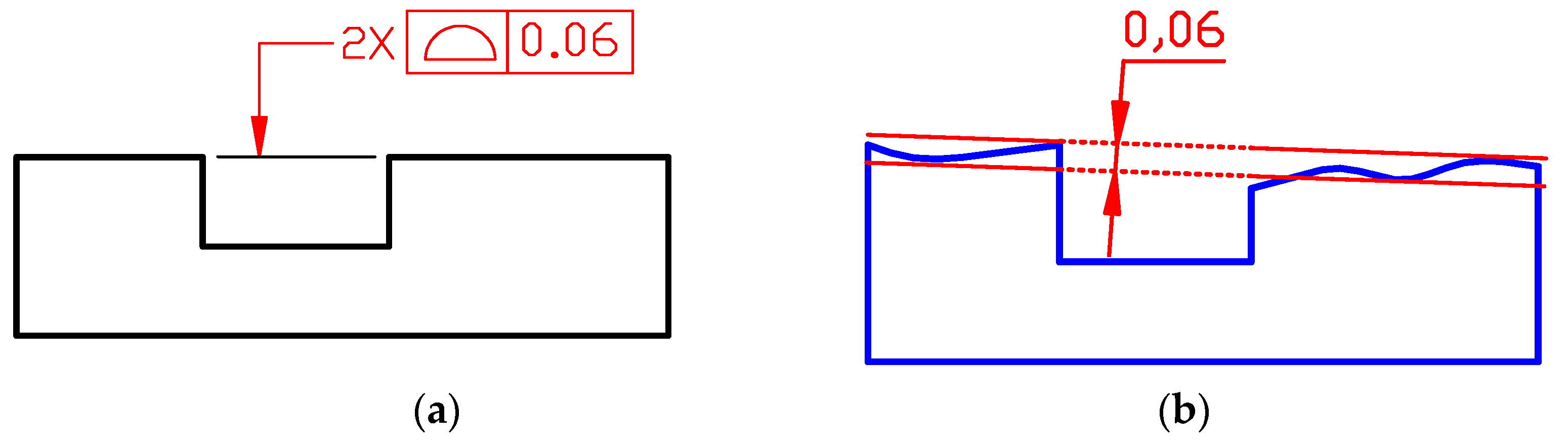
According to ASME Y14.5, when profile tolerance is applied to a few features without datums, the tolerance features are by default regarded as the interrupted feature (pattern of coplanar surfaces) and the tolerances are applied simultaneously. In Figure 7a the profile tolerance controls flatness and coplanarity of two nominally planar surfaces (Figure 7b).
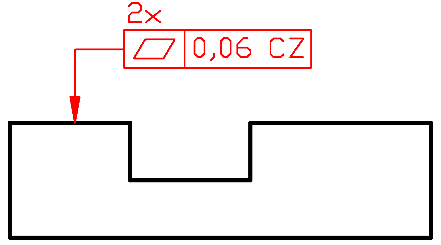
In the ISO GPS system, according to the independency principle [23], by default, each profile tolerance will be applied separately, the first one to the left top surface and the second one to the right top surface, thereby individually controlling the flatness of each surface. To make the specification easy to understand, it is better to indicate the flatness tolerance symbol instead of the surface profile. Of course, the part shown in Figure 7a is simple and it is easy to recognize that the top surfaces are flat, however, for more complex parts, the nominal geometry defined in CAD model specification of the surface profile tolerance may indicate that two surfaces have a free form with low curvature that is excluded when the flatness tolerance is applied. To create coplanarity, two individual tolerance zones should be constrained in location and orientation amongst themselves. The modifier CZ (combined zone) indicated after the tolerance value (Figure 8) creates the combined tolerance zone constituted by two parallel planes distance 0.06 mm apart, in which two extracted surfaces shall be contained simultaneously. It is easy to identify in Figure 8 that the tolerance zones are fixed by an implicit theoretically exact dimension TED = 0 mm.
The perpendicularity, parallelism and angularity tolerances have the same symbols in ASME Y14.5 and in the ISO GPS system. The perpendicularity, parallelism and angularity tolerances applied for planar surfaces of a part (integral features) define identical requirements in ASME Y14.5 and in the ISO GPS system. In both systems, the extracted (actual) surface should be contained in a tolerance zone that is limited by two parallel planes separated by a distance that is equal to the tolerance value specified in the second compartment of the tolerance indicator. It means that for the planar surface, each orientation tolerance limits form deviation (flatness) of a toleranced feature.
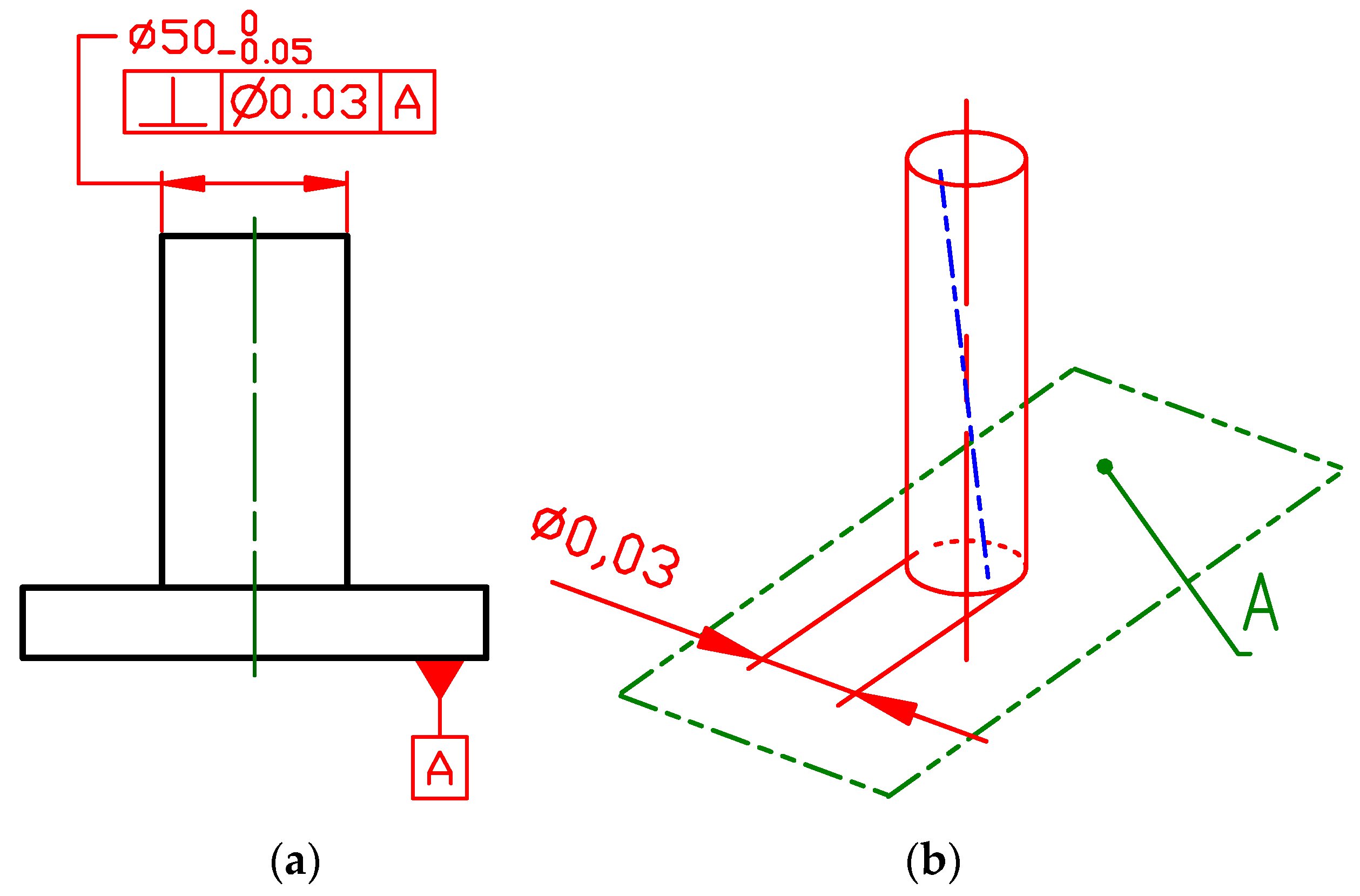
The perpendicularity (Figure 9a), parallelism and angularity tolerances applied for derived features (median line or median plane) create different requirements when specified according to ASME Y14.5 and in the ISO GPS system. According to ASME Y14.5, the orientation tolerance applies to the axis (symmetry plane) of an unrelated actual mating envelope, i.e., the maximum inscribed feature or minimum circumscribed feature (respectively, cylinder or two parallel planes). So, according to ASME Y14.5, the tolerance feature has the perfect form (Figure 9b).
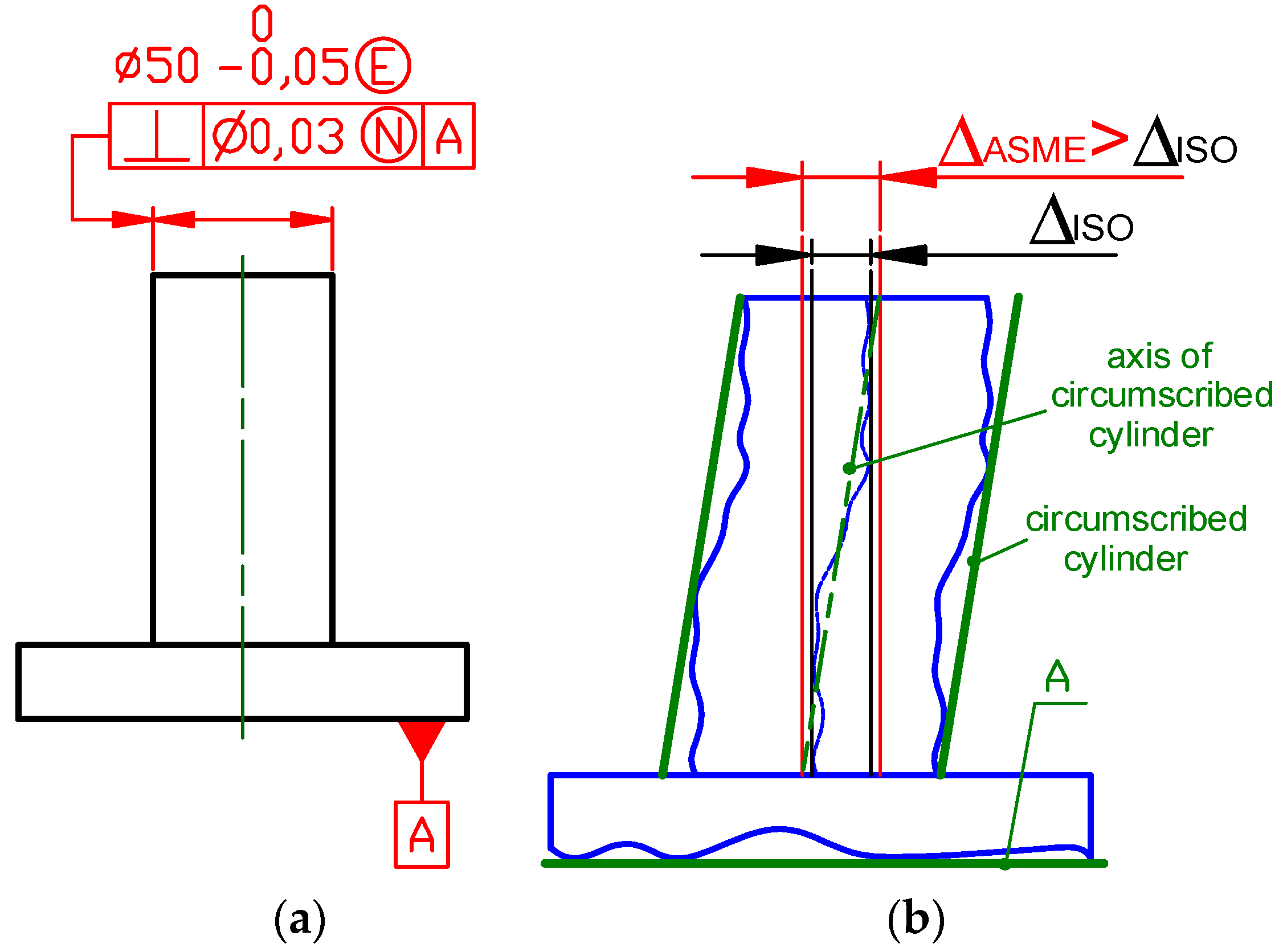
According to the ISO GPS system by default the orientation tolerance applies to the derived median line (actual axis) or derived median surface. It means that each orientation tolerance limits form deviation of the tolerance feature (respective median line straightness or median surface flatness). So additional modifier shall be added in specification according to the ISO GPS system to indicate that the specification does not apply to the indicated feature itself, but to a feature associated with it. In this case, the encircled N shall be placed after the tolerance value (Figure 10a) to indicate that the toleranced feature is defined as the derived feature (axis) of the associated minimum circumscribed cylinder – the cylinder that is circumscribed over the actual surface of a pin. Five associated tolerance feature specification elements were introduced in 2017 in the fourth edition of ISO 1101. The previous edition from 2012 has no tools to specify requirements identical to ASME Y14.5 specification.
It shall be noted that skipping form deviation of the toleranced axis for perpendicularity tolerance according to ASME Y14.5 will usually give a smaller deviation compare with the perpendicularity deviation assessed according to the default ISO GPS system requirement. However, the pin may have such a shape that deviation assed according to ASME Y14.5 specification is greater (Figure 10b).
ASME Y14.5-2018 locates features of size only by tolerances of position. The coaxiality (concentricity) and symmetry symbols that were available in previous editions of this standard have been removed. The coaxiality and symmetry tolerances in ASME Y14.5-2009 controlled the opposing median points of a feature of size. It means that for coaxiality, a set of points has to be examined in each cross-section, which is rarely a functional requirement and is not considered in the ISO GPS system standards. The meaning of the symmetry tolerance in ASME Y14.5-2009 was the same as the meaning of the symmetry tolerance in the ISO GPS system. In ASME Y14.5-2018, the position tolerance is used to control centre distances between features of size (holes, slots, bosses and tabs), location of patterns (groups) of the features of size with respect to the datum system, as well as the coaxial (Figure 11) and symmetrical relationships between features of size.
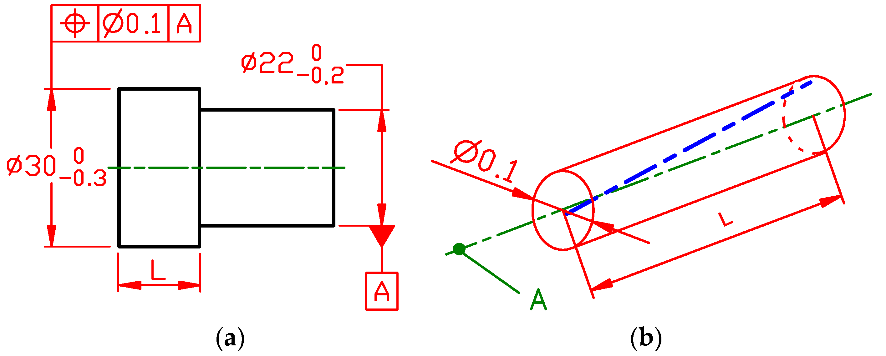
For the location of the derived feature (axis or symmetry plane), ASME Y14.5 applies only position tolerance. According to ASME Y14.5, the position tolerance is applied to the axis (symmetry plane) of an unrelated actual mating envelope, i.e., maximum inscribed feature or minimum circumscribed feature (respectively, cylinder or two parallel planes). The position tolerance (Figure 11a) is specified to control the coaxiality of the two-step shaft flange with respect to the datum A. According to ASME Y14.5, the tolerance feature has the perfect form (Figure 11b).
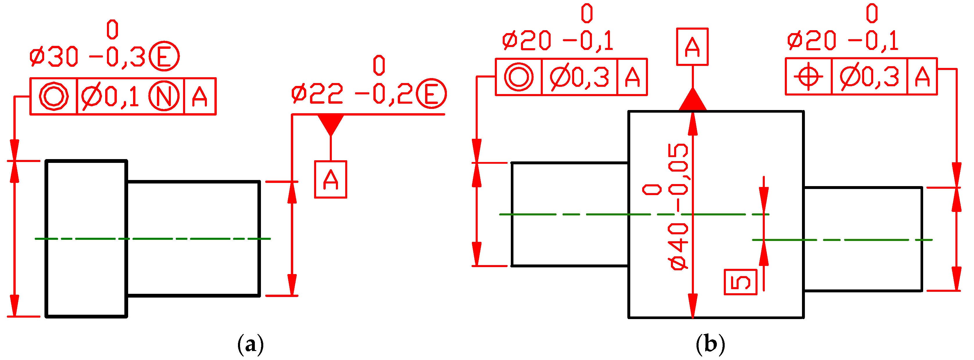
In Figure 12a, the coaxiality symbol with the encircled N placed after the tolerance value 0.1 mm is specified to secure in the ISO GPS system the same functional requirement as defined in Figure 11a. Of course, when in the ISO GPS system, the position tolerance symbol is specified instead of the coaxiality symbol; the meaning of specification is the same, but the coaxiality symbol clearly states that the theoretically exact dimension (TED) between the datum axis and the axis of the tolerance zone is equal to 0 mm. Specification of the position tolerance does not convey such information. The part in Figure 12 is simple and there is no doubt that there is no offset between the tolerance zone axis and the datum axis, but if a part will be more complex, application of coaxiality in the ISO GPS system is recommended as it is more informative.
According to ASME Y14.5, by default, the simultaneous requirement applies to the position and profile tolerances that are located by basic dimensions related to the set of datum features specified in the same order of precedence without the material modifiers or with the same maximum or least material requirements. In the simultaneous requirement, there is no translation or rotation between the datum reference frames of considered geometrical tolerances, therefore, all features create one pattern. This default approach may be cancelled by indication SEP REQT placed adjacent to each tolerance indicator. According to the ISO GPS system independency principle [23], by default, every GPS specification for a feature or relation between features shall be fulfilled independently of other specifications, except when a modifier that overrules the independency principle is stated.
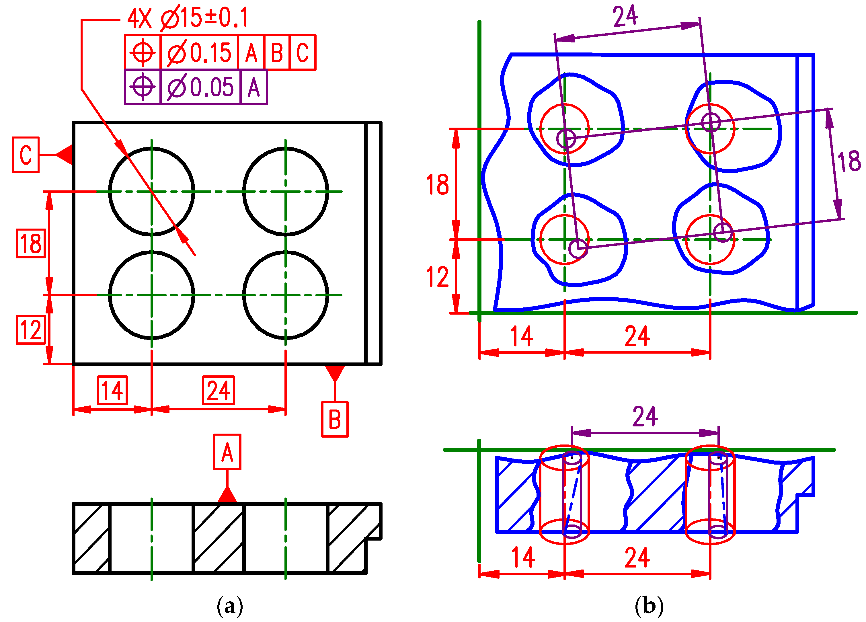
The plate with four holes is given in Figure 13a. Two position tolerances are indicated and both shall be considered separately. The position tolerance T = 0.15 mm with respect to the datum system A|B|C defines four cylindrical tolerance zones of diameter 0.15 mm located by theoretically exact dimensions (dimensions given in rectangular frames), within which the tolerance features—axes of the cylinders inscribed individually to each hole—shall be contained. The datum system A|B|C constrains all 6 degrees of freedom, so these four tolerance zones are locked (Figure 13b). The position tolerance T = 0.05 mm with respect to the datum A defines the next set of four cylindrical tolerance zones of diameter 0.05 mm that are perpendicular to the datum A and, due to ASME Y14.5’s default simultaneous requirement, their axes are defined as edges of the rectangular prism with the rectangle base 24 mm × 18 mm. The pattern of four cylindrical tolerance zones of diameter 0.05 mm may float, i.e., may translate into any direction parallel to the datum A (plane) and rotate around the axis perpendicular to the datum A. The axes of the four holes shall be within the largest tolerance zones and the smaller tolerance zones, as is shown in Figure 13b.
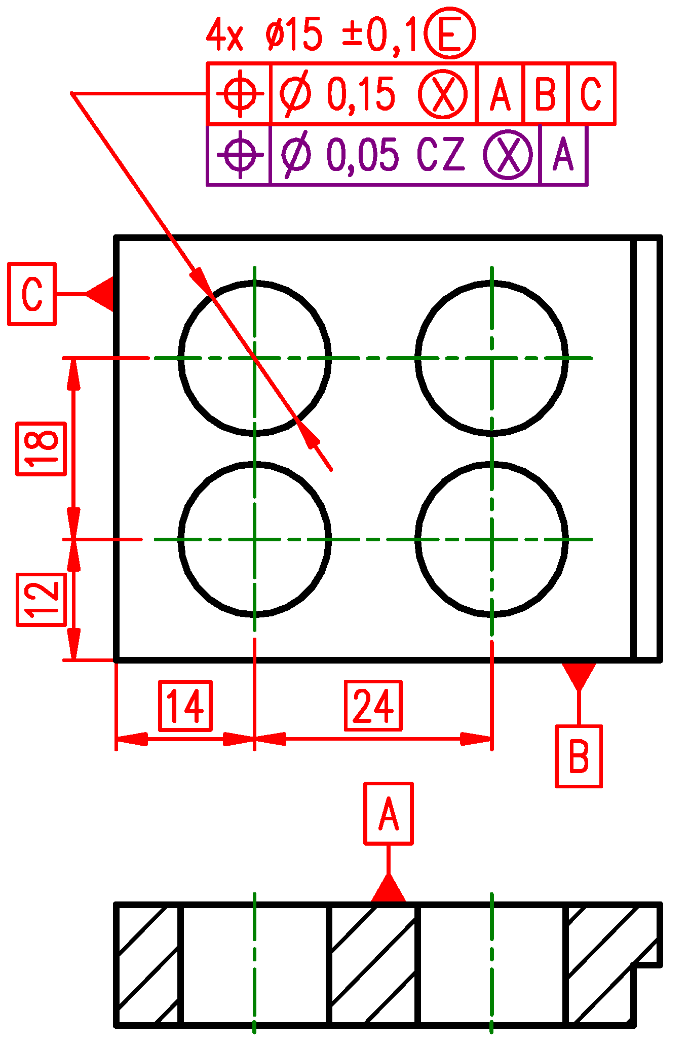
In the ISO GPS system, due to different defaults to specify the same requirement, two modifiers shall be indicated (Figure 14). The modifier CZ, combined zone, shall be used to create the pattern [26] of four cylindrical tolerance zones of diameter 0.05 mm with respect to the datum A and the encircled X shall be used to indicate that the tolerance feature is defined as the derived feature (axis) of the associated maximum inscribed cylinder—the cylinder that is inscribed into the actual surface of each hole.
The same plate with four holes is given in Figure 15a, but now the composite feature control frame is specified. According to ASME Y14.5, the composite feature control frame contains a single geometrical characteristic symbol (position or profile), followed by two or more segments, each containing tolerance and any required datum references. The uppermost segment has the largest tolerance value and locates the pattern with respect to the specified datum system. Each lower segment is a feature-relating control that governs the smaller position tolerance within the pattern (feature-to-feature relationship). The datum features specified in the second and all lower segments of a composite feature control frame constrain only rotational degrees of freedom with respect to specified datums, translational degrees of freedom are not constrained. The datum features in the lower segment shall be specified in the same order of precedence as in the upper segment, and if not listed all, they may be skipped in the order from right to left.
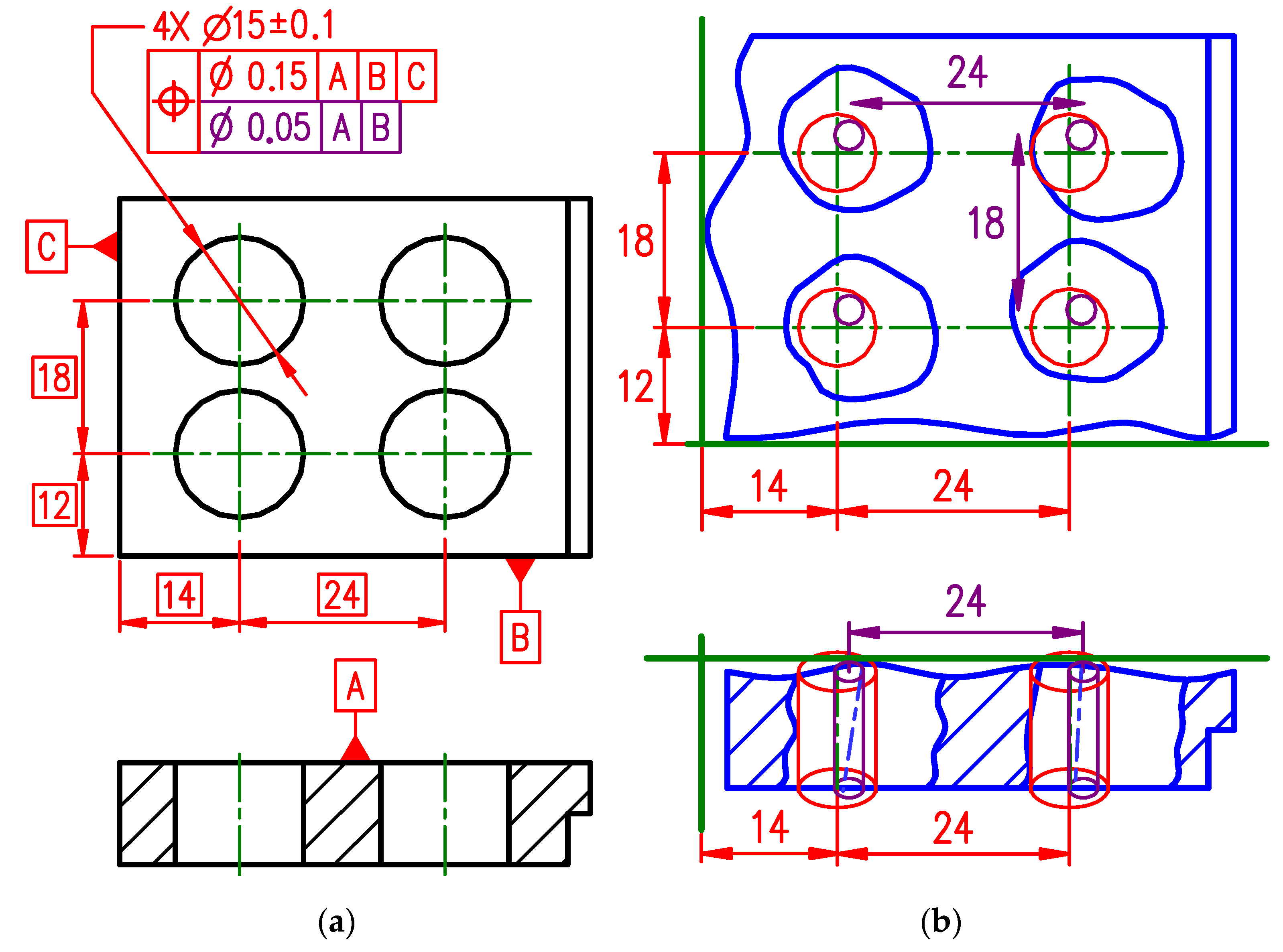
In Figure 15a, the position tolerance symbol is “shared” twice. The position tolerance T = 0.15 mm with respect to the datum system A|B|C defines four cylindrical tolerance zones of diameter 0.15 mm located by theoretically exact dimensions, within which the tolerance features—axes of the cylinders inscribed individually to each hole—shall be contained. The datum system A|B|C constrains all 6 degrees of freedom, so these four tolerance zones are locked (Figure 15b). The position tolerance T = 0.05 mm with respect to the datum system A|B due to ASME Y14.5’s default simultaneous requirement defines the next set of four cylindrical tolerance zones of diameter 0.05 mm with axes defined as edges of the rectangular prism with the rectangle base 24 mm × 18 mm. So, the requirement for the relative location between the axes of the four holes is tightened. The datum B in the datum system A|B constrains only the orientation of the axes of the four holes. Theoretically, exact linear dimensions apply only between the holes but do not apply to datum B—the linear theoretically exact dimension of 12 mm is not considered. The pattern of four holes may float up and down with respect to the datum B, but the pattern cannot rotate with respect to the datum B. The axes of the four holes shall be within the largest tolerance zones and the smaller tolerance zones simultaneously, as is shown in Figure 15b.
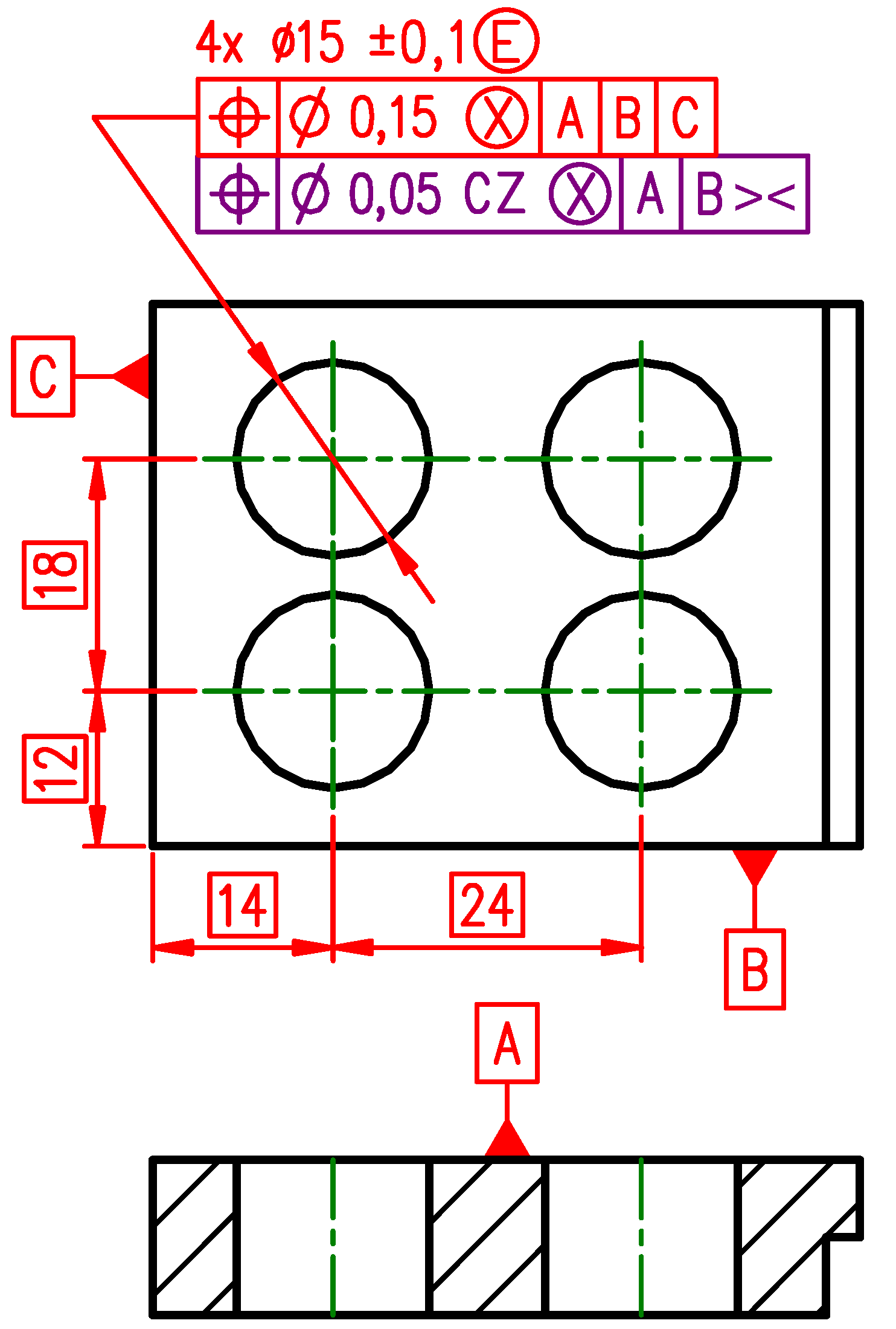
The ISO GPS system does not use the concept of composite tolerance. The function depicted by the meaning in Figure 15b is secured by stacked two-level tolerance indications (Figure 16). The upper tolerance indicator is identical, as in Figure 14, and in the lower tolerance indicator the modifier >< (for orientation constraint only) is specified after the datum B. The modifier >< indicates that datum the B establishes only orientation for the pattern of tolerance zones of diameter T = 0.05 mm. As it was explained for the indication in Figure 14, modifier CZ is specified after the tolerance value T = 0.05 to override the ISO GPS system default independency principle to create the pattern of the four holes and the encircled X indicates that the axes of maximum inscribed cylinders shall be contained as the tolerance features in both tolerance zone patterns.
The position tolerances in Figure 13a and Figure 15a are locating axes of the holes. According to ASME Y14.5, the axis of the hole is derived by using the actual mating envelope, which contacts the highest points of the hole surface (axis of the maximum inscribed cylinder). The location of the axis is often used because it is intuitive and easy to explain. In an assembly, from the functional point of view, the surfaces of holes and pins come into contact with the mating part. This may be well observed when a functional gauge is used to verify specified position tolerances. The hole axis is not located, but a hole surface must not violate the maximum material virtual condition boundary. The difference in the axis and surface interpretation is usually negligible. The problem may occur when a hole is significantly out of cylindricity and only the axis of such a hole is controlled. To get rid of the mentioned problem, maximum material requirement (MMR), marked by the encircled M [13,27], is specified. It should be mentioned that the new edition of ISO 2962 [27] was just published (June 2021).
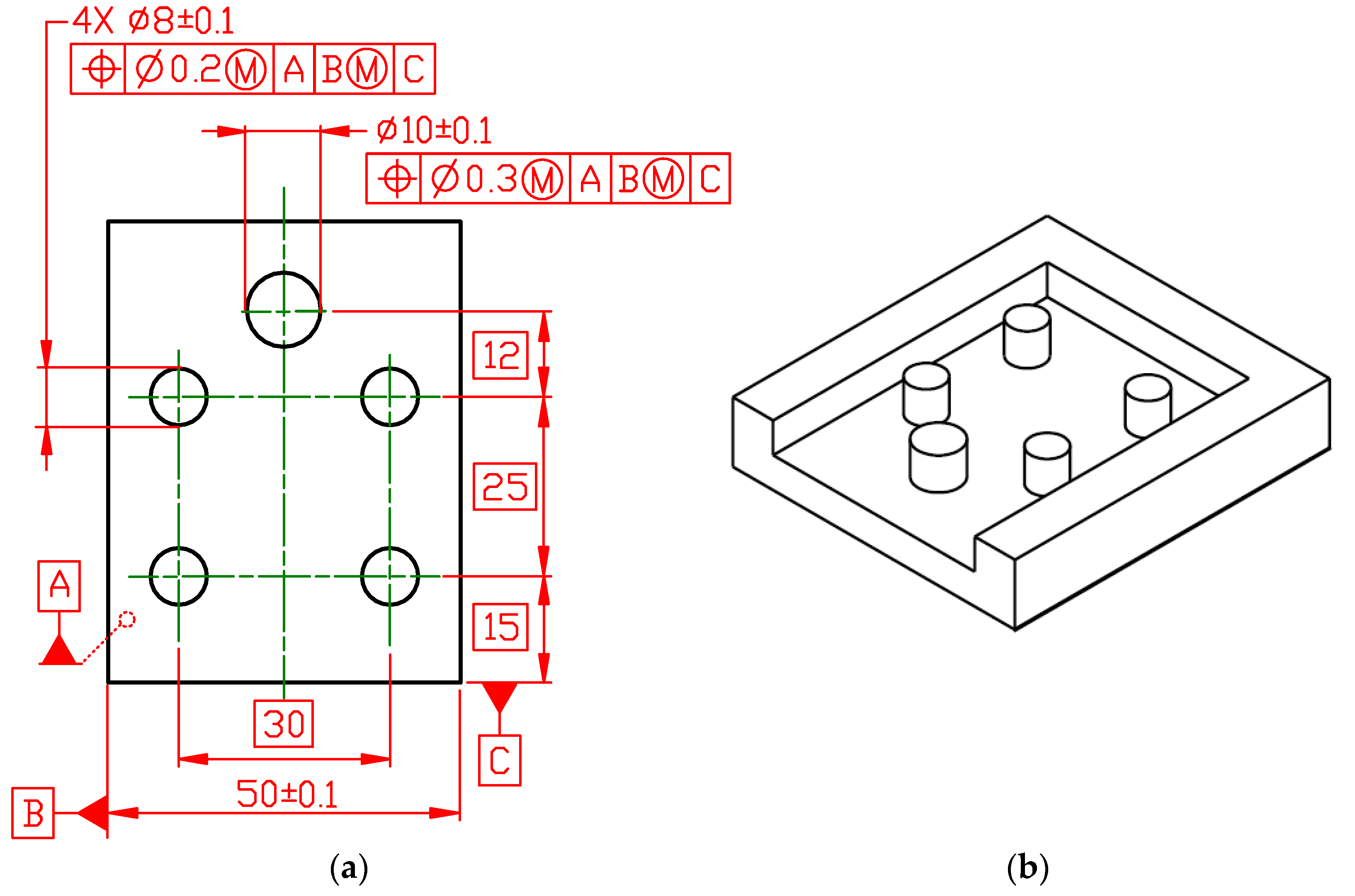
According to ASME Y14.5, five holes in the plate (Figure 17a) shall be considered as a pattern and all tolerances apply simultaneously. The hole locations shall be verified in one attempt by material gauge: a close-end slot with four pins of diameter equal to maximum material virtual size MMVS = 7.7 mm [27] and one pin of diameter MMVS = 9.6 mm (Figure 17b) located with respect to the datum system A|B ![Applsci 11 08269 i002]() |C. The plate during verification shall lay on the slot bottom that establishes the datum A. Due to the maximum material requirement specified for the datum B, the sidewalls of the plate shall not violate the maximum material virtual condition MMVC boundary established by two parallel planes, a distance 50.1 mm apart, perpendicular to the datum A. The MMVC is represented in the gauge by its flank walls. Finally, at least one point of contact is required for the datum feature indicated by letter C with the gauge groove closing side that establishes the datum C. The maximum material requirement specified for the datum B produces additional mobility for the plate with a width smaller than 50.1 mm when it is inserted into the gauge grove. It means, taking into account ASME Y14.5’s default simultaneous requirement, that all five holes may be shifted in the same direction and thanks to the smaller plate width it may be possible to move (translate/rotate) the plate to insert the plate holes into the gauge pins.
|C. The plate during verification shall lay on the slot bottom that establishes the datum A. Due to the maximum material requirement specified for the datum B, the sidewalls of the plate shall not violate the maximum material virtual condition MMVC boundary established by two parallel planes, a distance 50.1 mm apart, perpendicular to the datum A. The MMVC is represented in the gauge by its flank walls. Finally, at least one point of contact is required for the datum feature indicated by letter C with the gauge groove closing side that establishes the datum C. The maximum material requirement specified for the datum B produces additional mobility for the plate with a width smaller than 50.1 mm when it is inserted into the gauge grove. It means, taking into account ASME Y14.5’s default simultaneous requirement, that all five holes may be shifted in the same direction and thanks to the smaller plate width it may be possible to move (translate/rotate) the plate to insert the plate holes into the gauge pins.
 |C. The plate during verification shall lay on the slot bottom that establishes the datum A. Due to the maximum material requirement specified for the datum B, the sidewalls of the plate shall not violate the maximum material virtual condition MMVC boundary established by two parallel planes, a distance 50.1 mm apart, perpendicular to the datum A. The MMVC is represented in the gauge by its flank walls. Finally, at least one point of contact is required for the datum feature indicated by letter C with the gauge groove closing side that establishes the datum C. The maximum material requirement specified for the datum B produces additional mobility for the plate with a width smaller than 50.1 mm when it is inserted into the gauge grove. It means, taking into account ASME Y14.5’s default simultaneous requirement, that all five holes may be shifted in the same direction and thanks to the smaller plate width it may be possible to move (translate/rotate) the plate to insert the plate holes into the gauge pins.
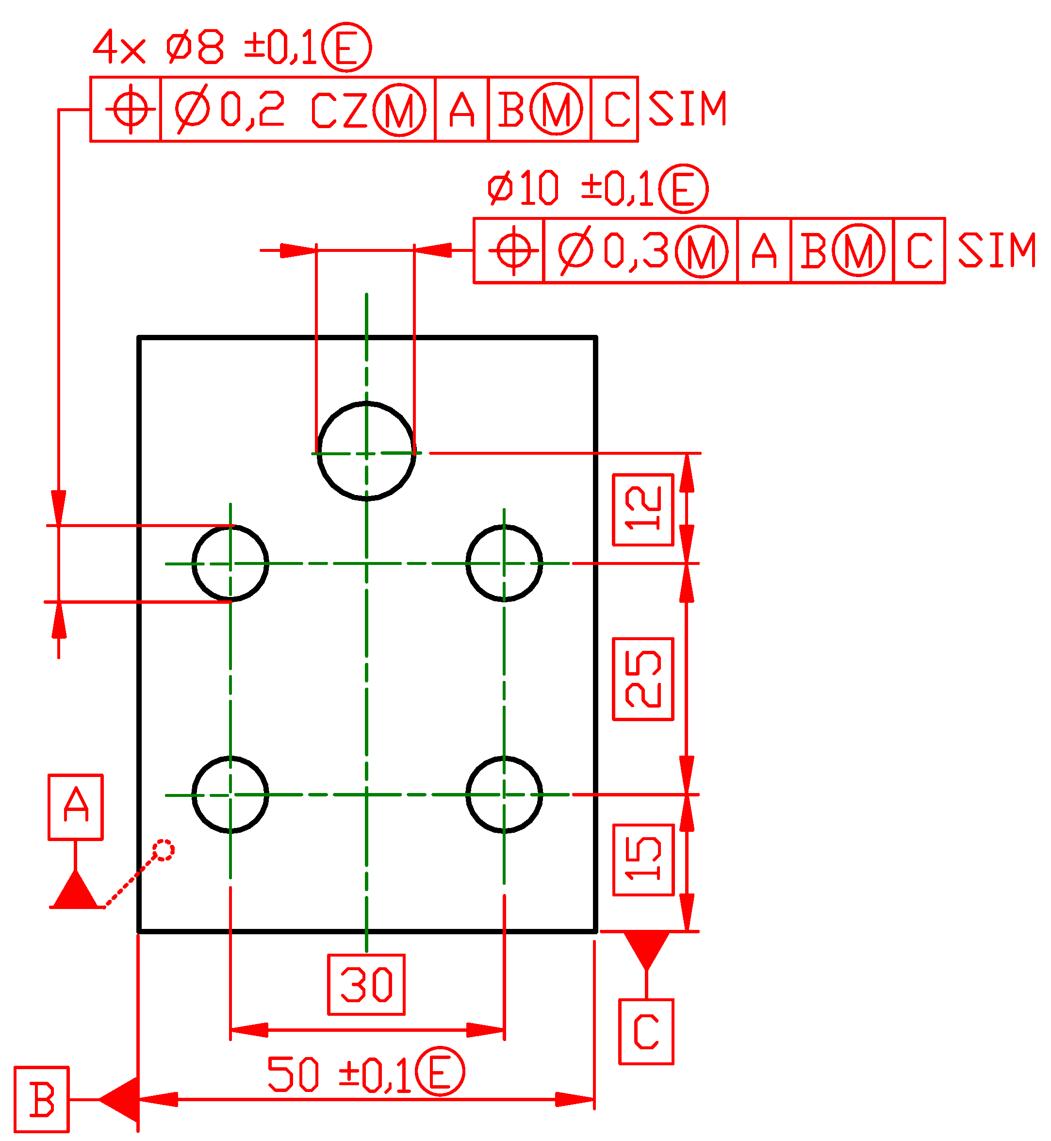
In the ISO GPS system, according to the independency principle, by default, a geometrical specification that applies to more than one single feature applies to those features independently. So, the tolerance zones defined by one tolerance indicator or by several tolerance indicators shall be considered independently. Looking at the plate shown in Figure 17a, it is, functionally, very likely that four 8 mm diameter holes shall be located together. To indicate this in the ISO GPS system, modifier CZ (combined zone) shall be specified after position tolerance T = 0.2 mm in the tolerance indicator (Figure 18). The 10 mm hole is another geometrical feature with another position tolerance, T = 0.3 mm. To link together these two position tolerances in one requirement, the modifier SIM (simultaneous requirement) is indicated on the right side of each position tolerance indicator (Figure 18). In cases where, the modifier SIM will be not specified the position tolerances for the pattern of 8 mm diameter holes and position tolerance for the single 10 mm hole shall be verified separately. For the two material gauges, close-end slots are necessary. The first gauge has four pins with diameters equal to the maximum material virtual size, MMVS = 7.7 mm. The second gauge has one pin of diameter MMVS = 9.6 mm. It means that when the plate width is smaller than 50.1 mm, then the 8 mm hole pattern and the 10 mm hole may be shifted away in opposite directions. The encircled M—MMR (maximum material requirement [27]) specified after the secondary datum introduces mobility with respect to boundaries defined by the MMC condition. In the case where the datum B will be specified without MMR, the datum system A|B|C is constraining all degrees of freedom and the modifier SIM is not necessary.
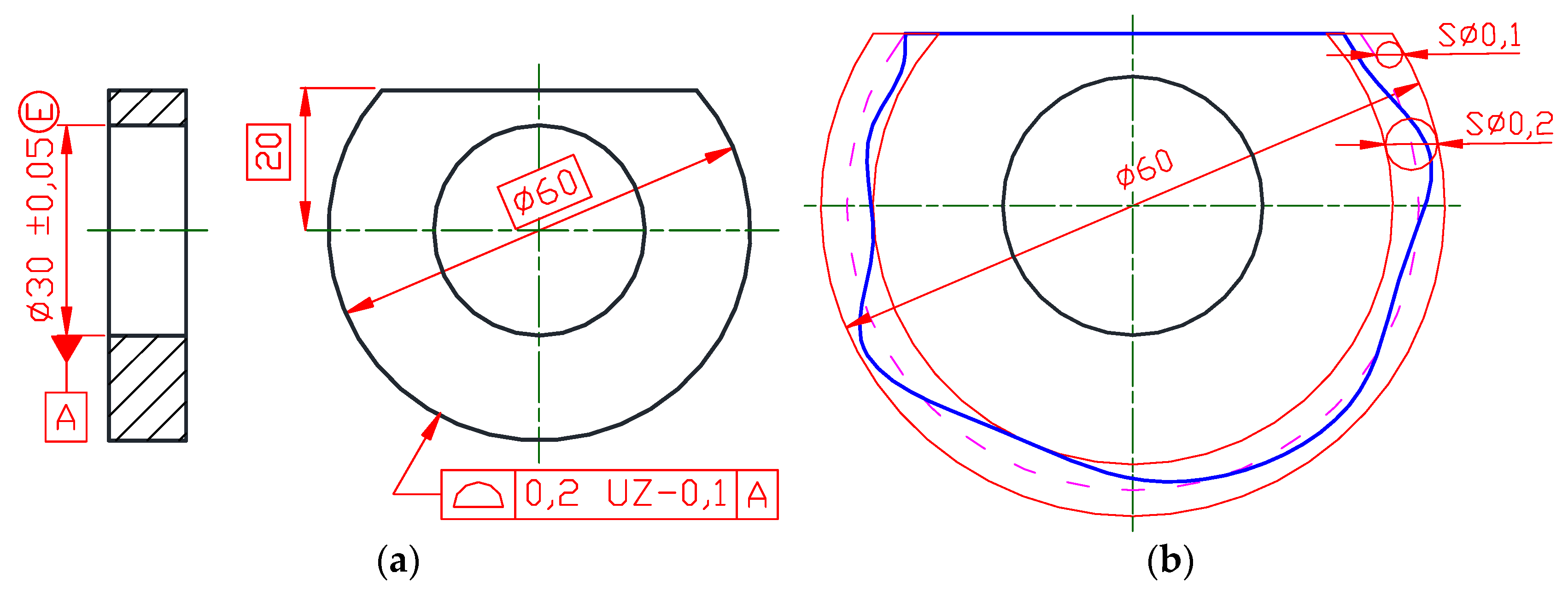
The surface profile tolerance is used to define a tolerance zone to control the combination of size, form, orientation and location of a feature (Figure 19a), or features, with reference to theoretically exact profile(-s). The surface profile tolerance zones may or may not be indicated with respect to the datum or datum system. By default, in the ASME Y14.5 and in the ISO GPS system, for the surface profile tolerance the tolerance zone is bilaterally (equally) disposed on both sides of the theoretically exact feature (profile) by equal offsets. In some instances, an unequally disposed tolerance zone is required. For example, the disc shown in Figure 19a shall slide precisely along the groove in a cube. It will be quite convenient for such a function to specify the same theoretically exact dimension for both parts and displace, respectively, tolerance zones in both features to eliminate the overlap that will occur in the case of equally disposed tolerance zones. The encircled U placed after tolerance T = 0.2 mm (Figure 19a) indicates that the tolerance zone is unequally disposed. The 0 mm following the encircled U indicates the value of the tolerance in the direction that would allow additional material to be added to the theoretically exact profile. So, in Figure 19, the maximum material boundary coincides with the theoretically exact profile. All points of the extracted profile shall be contained in the tolerance zone shown in Figure 19b, which starts from the theoretically exact feature and extends into the material.
A quite different notation to specify the unequally disposed tolerance zone is implemented in the ISO GPS system (Figure 20a). The value 0.1 mm indicated after modifier UZ (specified tolerance zone offset) sets the diameter of the spheres defining the new shifted theoretically exact feature. This new offset theoretically exact feature is defined as a surface that envelops auxiliary spheres of diameter 0.1 mm (Figure 20b) that are rolled on a primary theoretically exact feature defined by the theoretically exact dimension with respect to the datum A. The datum A, the axis established by the cylinder inscribed in the hole, defines the origin of the theoretically exact radius of 30 mm. The sign plus or minus given between the modifier UZ and the auxiliary sphere diameter determines whether the spheres shall be rolled outside (the positive value) or inside (the negative value) of the theoretically exact feature material. The offset tolerance zone (Figure 20b) is limited by two surfaces enveloping spheres with diameters of 0.2 mm, the centres of which are situated on the theoretically exact surface that was generated by the auxiliary spheres of diameter 0.1 mm.
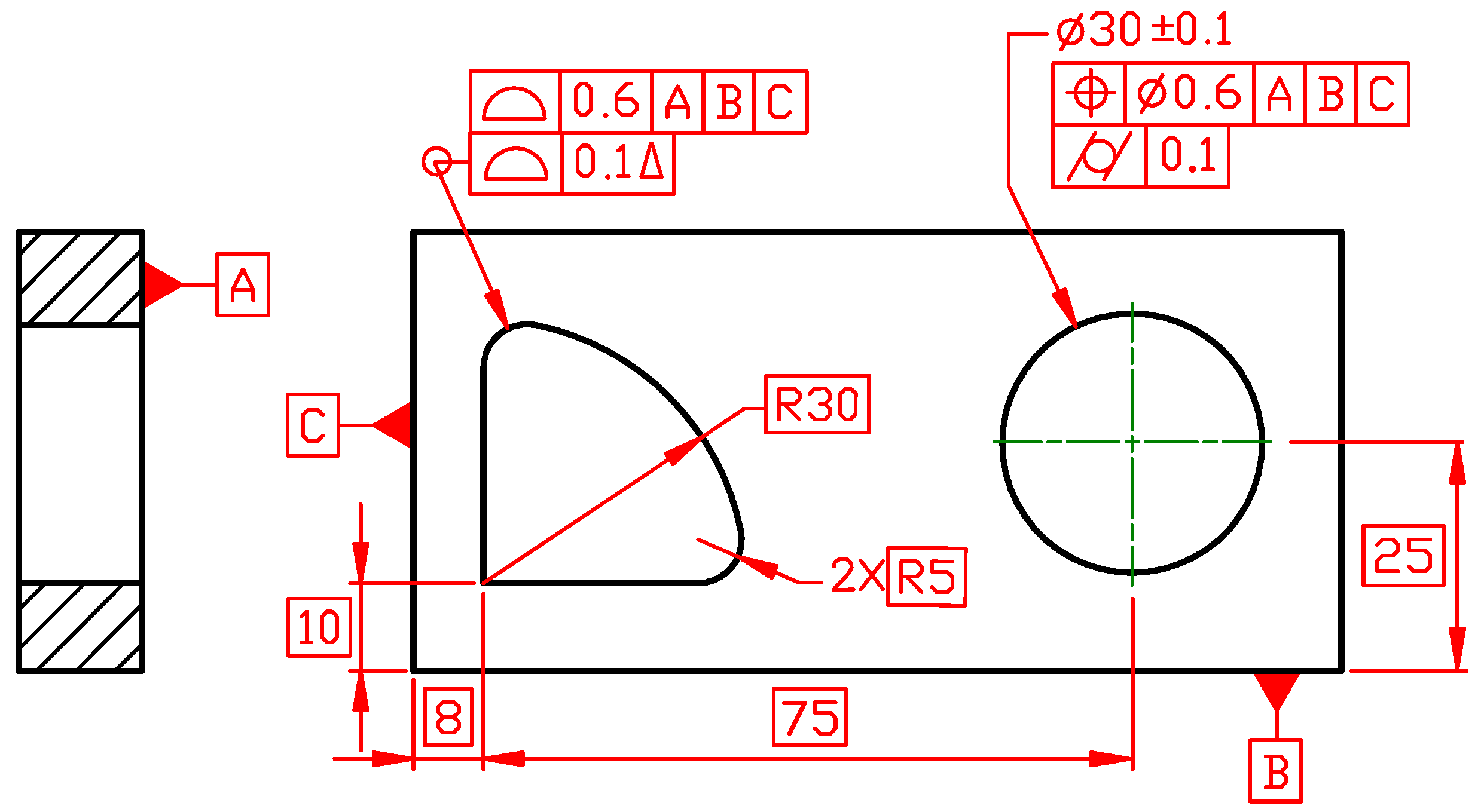
For many years, as was mentioned above, the profile tolerance was used to control a combination of size, form, orientation and location respectively to the datum indication. It is due to ASME Y14.5’s default that the profile tolerance zone follows the theoretically exact profile of the considered feature. There was no possibility to control only the form of a toleranced non-planar feature, even for the profile tolerance without a datum(s) because it shares the same tolerance zone for dimensions and form. In ASME Y14.5-2018, a new modifier, dynamic profile, indicated by a triangle placed after the tolerance value in the tolerance indicator (Figure 21) was introduced. The dynamic profile modifier shall be specified when it is necessary to refine the form but not the dimensions of the toleranced feature. The form of the toleranced feature is controlled independently of the dimensions. When the dynamic profile tolerance is applied, the tolerance zone may progress (expand or contract) normally to the theoretically exact profile while maintaining its width. The offset between the boundaries of the dynamic profile tolerance zone remains fixed but the size of the boundaries is variable. The actual feature shall simultaneously be within the dynamic profile tolerance zone and the other specified tolerance zone.
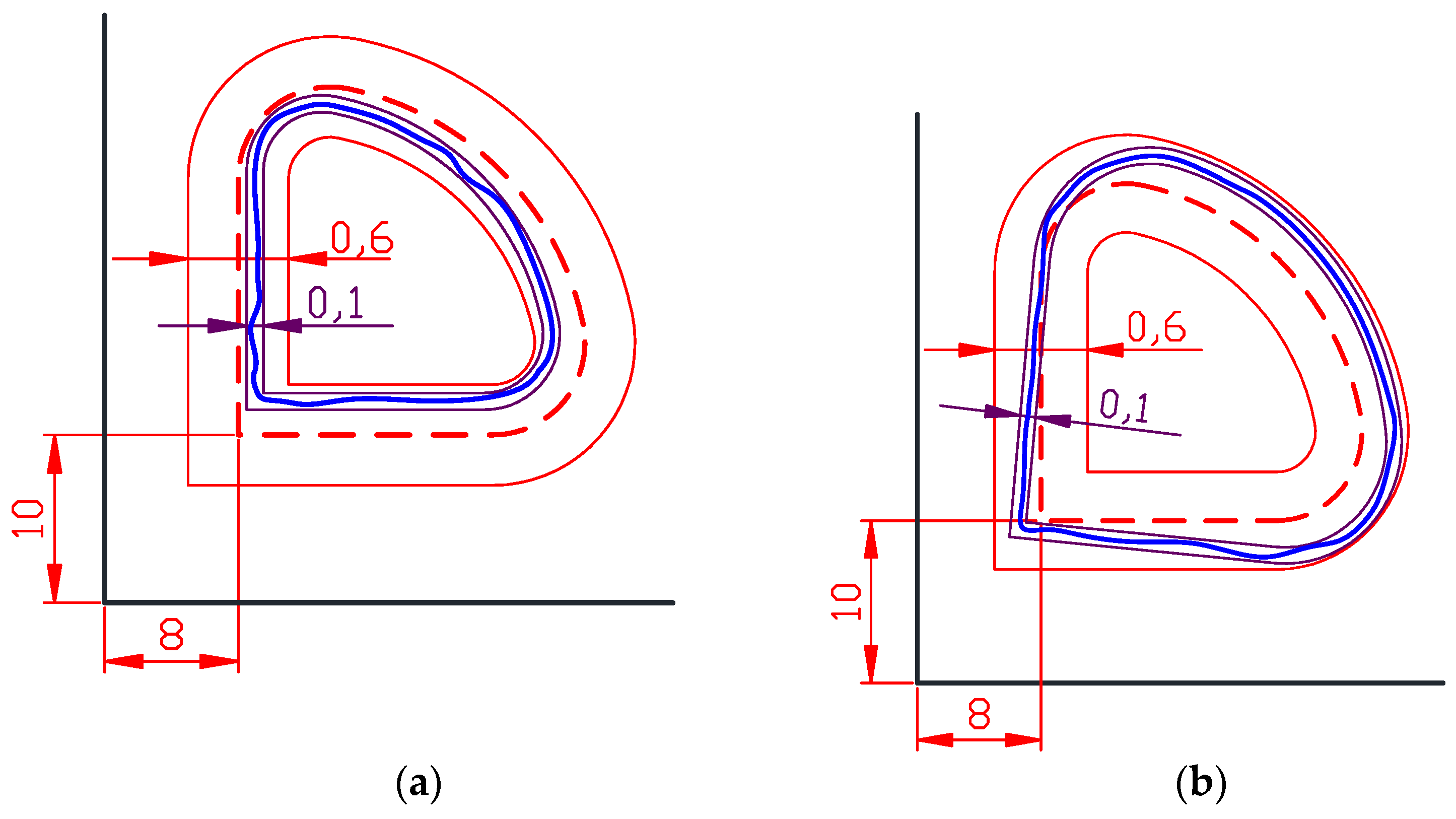
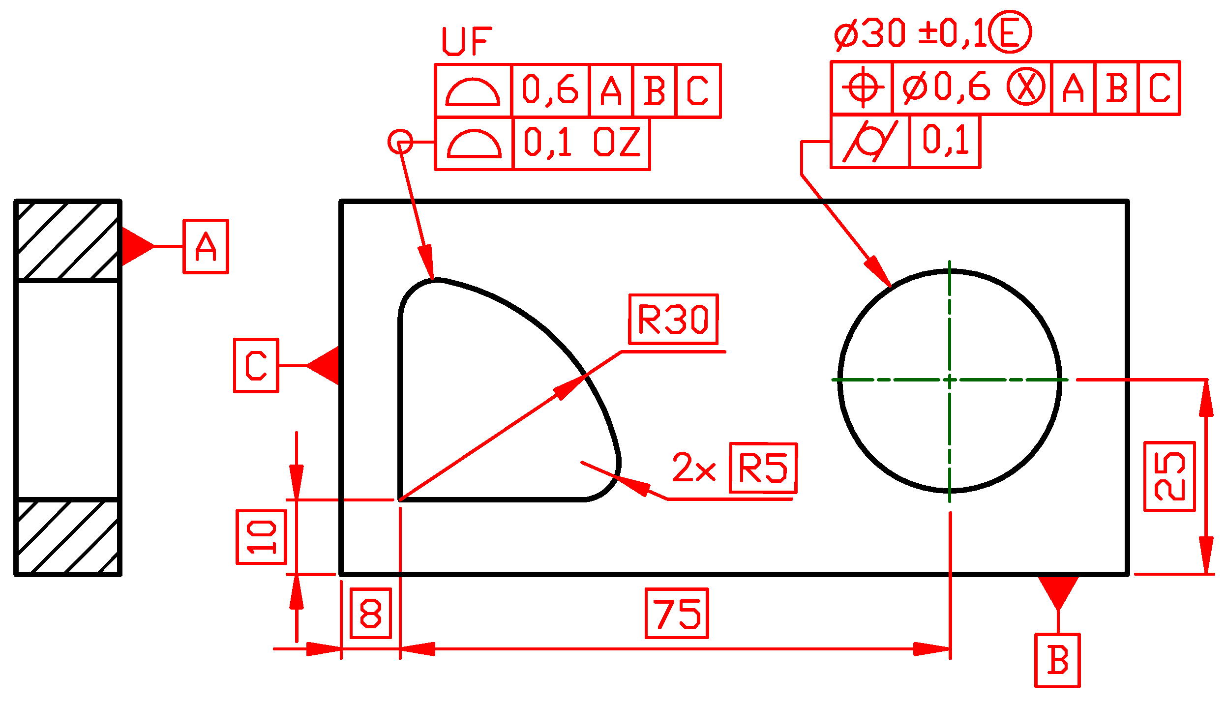
The dynamic surface profile concept may be well explained on the plate shown in Figure 21. The right cylindrical hole is located by position tolerance T = 0.6 mm with respect to the datum system A|B|C and the hole size (surface variability) is controlled by Rule #1 with the diameter limit deviations ±0.1 mm. It means that the hole form deviations due to the size tolerance are limited to 0.2 mm. The designer decided that this is too much and additionally specified the cylindricity tolerance T = 0.1 mm. The extracted cylindrical hole surface shall be contained between two coaxial cylinders with the difference in radii of 0.1 mm. The left hole has a complex shape; therefore, it is located by the surface profile tolerance T = 0.6 mm with respect to the datum system A|B|C. The location of the tolerance zone is fixed and the tolerance zone is divided symmetrically into both sides of the theoretically exact profile (marked by the dashed line in Figure 22). The surface profile tolerance applies all around the theoretically exact profile, which is indicated by the small circle placed on the intersection on the leader line and the reference line. The extracted quarter-cylindrical hole surface shall be contained between two boundary surfaces 0.6 mm apart. It means that the quarter-hole form deviations are limited to 0.6 mm. The designer accepted 0.6 mm variability for the quarter-hole in the delivered lots, but in the particular plate, the left hole form deviation is limited to 0.1 mm by the indicated dynamic surface profile tolerance. Regardless of the size of the left hole, its form has to be confined in its separate tolerance zone. This gives a tighter control of the form without tightening the size tolerance given to the feature. The dynamic surface profile tolerance zone is functionally equivalent to the cylindricity tolerance zone applied to the right hole. The datum references may also be used with the dynamic profile to control form, orientation and location without size.
The equivalent limits for the left hole specified with the ISO GPS system indications are shown in Figure 23. The modifier OZ (unspecified linear tolerance zone offset) was introduced in the latest edition of ISO 1101 [12] and its application is explained in ISO 1660 [28]. The modifier OZ indicates that the surface profile tolerance zone is allowed to be offset from being symmetrical around the theoretically exact feature by a constant but unspecified amount. The width of the tolerance zone, T = 0.1 mm, is given in front of the OZ. The modifier UF (united feature) is specified in the upper adjacent area to make it explicit that the specification applies to the compound integral feature considered as a single feature.
It should be noted that the surface profile tolerance in ASME Y14.5 is the only tolerance that may be applied to locate a nominally flat surface. In the ISO GPS system, both the surface profile tolerance and the position tolerance may be applied to locate the nominally flat surface and have the same meaning. However, to get better readability of the drawings, it is recommended to apply the position tolerance to locate nominally flat surfaces. The position tolerance in the ISO GPS system carries clear information that the tolerance feature is a nominally flat surface. When the profile tolerance is specified in the ISO GPS system, it is necessary to verify in the drawing or in the CAD model that there is no indication that the feature is nominally non-flat. In ASME Y14.5, specification of the position tolerance is restricted to the derived features of the features of size.
It is worth mentioning that both systems recommend using the profile tolerances as general geometrical specifications and general size specifications to ensure univocal specifications for functionally less important geometrical features of a part [13,29].
The differences and similarities between the two tolerancing systems are summarized in Table 1. In the second column, a graphical indication that is available in ASME Y14.5-2018 is given. The third column shows whether the identical symbols are available in the ISO GPS system. The crossed table cell in the third column indicates that the identical graphical notation exists in the ISO GPS system, but the meaning of the identical indication is different. In such a case, in the fourth column, additional symbols that shall be used as an indication to specify the same requirement for a toleranced feature are listed.
3. Conclusions
The challenge is the parallel existence of two geometrical tolerancing systems that are used to control a part size, form, orientation and location deviations. The ISO GPS system standards and National American Standard ASME Y14.5-2018 establish communication protocols between designers, manufacturing engineers and inspection staff that are particularly helpful in a global economy where parts may be designed in one country, produced in another and assembled elsewhere. The proper specification of allowable geometrical deviations is a key issue for successful fabrication of parts that enable the required assembly and performance. Miscommunication during specification and misinterpretation of symbols given in the technical product documentation can result in controversy during outsourcing and verification of parts, and can cause expensive scraps or reworks.
It should be noted that the same concepts or rules that exist in National American Standard ASME Y14.5-2018 and in the ISO GPS system standards are called by different names or coded graphically in a different manner. For example, feature control frame (ASME Y14.5) versus tolerance indicator (ISO GPS), basic size (ASME Y14.5) versus theoretically exact dimension (ISO GPS), true position (ASME Y14.5) versus theoretically exact position (ISO GPS), true profile (ASME Y14.5) versus theoretically exact profile (ISO GPS), maximum material boundary (ASME Y14.5) versus maximum material condition (ISO GPS), etc. In this paper, to make it more clear, in most cases only the ISO GPS system terms have been used, even in the case of discussion of dimensional and geometrical tolerances specified according to ASME Y14.5.
The problem of transformation from ASME Y14.5 specifications to the ISO GPS system specifications has been discussed in the paper in regards to selected cases for size, form, orientation and location specifications. Many people believe that specifications in both systems are identical because both systems have the same symbols for form, orientation, location and runout tolerances. This is not true. Many default rules are different. Moreover, there are cases when the same graphical symbol is used in the ASME standard and in the ISO GPS system but have different interpretations—sometimes the same symbol recalls different extracted features to which a tolerance is applied. This is a danger for less experienced designers, manufacturers and quality staff.
Table 1 was developed to summarize the question of differences and similarities between ASME Y14.5 and the ISO GPS system tolerancing tools. The novelty of this paper can be found in providing detailed information regarding how use the ISO GPS system indicators to express limits for a part’s geometry variation that were initially expressed by symbols given in ASME Y14.5. This paper focused on tools given in recently published ISO GPS standards. Table 1 shows that there are differences in syntax and semantics in geometrical tolerance indications. The differences in semantics are more dangerous because the same syntax (the same graphical representation) establishes another geometrical requirement that may be less or even not at all related to a part function.
Currently, no computer tools are available to transfer specifications made according to the ASME Y14.5 standard to specifications made according to the ISO GPS system’s rules. Education at universities and vocational trainings should cover tolerancing and knowledge in geometry assurance to a greater extent [2,30]. At present, practice-oriented factory training courses [31] can help the industry to have highly skilled personnel to perform a manual transformation of geometrical tolerances specified according to the ASME Y14.5 standard to geometrical tolerances specified according to the ISO GPS system. This is the first step, but a future possibility for such transformation shall be built-in commercial CAD systems.
The discussed cases of conversion from ASME Y14.5 specifications to the ISO GPS system do not cover all possible tasks that may face designers and production and quality staff in the industry, however, the most critical issues were considered. The paper’s aim was to highlight that in both systems there are a number of different default interpretations, as well as the fact that the meaning of the same symbols may be different always or only in certain cases.
Funding
This research received no external funding.
Conflicts of Interest
The author declares no conflict of interest.
References
- Walter, M.S.J.; Klein, C.; Heling, B.; Wartzack, S. Statistical Tolerance Analysis—A survey on awareness, use and need in German industry. Appl. Sci. 2021, 11, 2622. [Google Scholar] [CrossRef]
- Wärmefjord, K.; Söderberg, R.; Schleich, B.; Wang, H. Digital twin for variation management: A general framework and identification of industrial challenges related to the implementation. Appl. Sci. 2020, 10, 3342. [Google Scholar] [CrossRef]
- Dahiwal, R.; Aschenbrenner, A.; Schleich, B. Evaluation of the effects of geometrical deviations on the fatigue life and vibrations of cylindrical roller bearings. Bear. Word J. 2018, 3, 7–21. [Google Scholar]
- Rupal, B.S.; Anwer, N.; Secanellc, M.; Qureshi, A.J. Geometric tolerance and manufacturing assemblability estimation of metal additive manufacturing (AM) processes. Mater. Design 2020, 194, 1–15. [Google Scholar] [CrossRef]
- Welcome to ISO/TC 213. Available online: https://committee.iso.org/home/tc213 (accessed on 16 June 2021).
- Humienny, Z. State of art in standardization in GPS area. CIRP J. Manuf. Sci. Technol. 2009, 2, 1–7. [Google Scholar] [CrossRef]
- Humienny, Z. State of art in standardization in the geometrical product specification area a decade later. CIRP J. Manuf. Sci. Technol. 2021, 33, 42–51. [Google Scholar] [CrossRef]
- Morse, E.P.; Shakarji, C.M.; Srinivasan, V. A Brief analysis of recent ISO tolerancing standards and their potential impact on digitization of manufacturing. Procedia CIRP 2018, 75, 11–18. [Google Scholar] [CrossRef]
- Tornincasa, S. Technical Drawing for Product Design. Mastering ISO GPS and ASME GD&T; Springer: Berlin/Heidelberg, Germany, 2020. [Google Scholar]
- Henzold, G. Geometrical Dimensioning and Tolerancing for Design, Manufacturing and Inspection. A Handbook for Geometrical Product Specification Using ISO and ASME Standards; Butterworth-Heinemann: Kidlington, UK, 2020. [Google Scholar]
- Gill, P.S. Geometric Dimensioning and Tolerancing (Including Tolerance Stackups); S.K. Katara & Sons: New Delhi, India, 2019. [Google Scholar]
- ISO 1101:2017 Geometrical product Specifications (GPS)—Geometrical Tolerancing—Tolerances of Form, Orientation, Location and Run-Out; International Organization for Standardization: Geneva, Switzerland, 2017.
- ASME Y14.5-2018 Dimensioning and Tolerancing. Engineering Product Definition and Related Documentation Practices; American Society of Mechanical Engineers: New York, NY, USA, 2018.
- Krulikowski, A. Survey Results on the Usage of ISO GPS and ASME Y14.5 Standards. Available online: https://krulikowskiconsulting.com/survey-results-on-the-usage-of-iso-and-asme-y14-5-standards/ (accessed on 16 June 2021).
- ASME Y14.5.1-2019. Mathematical Definition of Dimensioning and Tolerancing Principles; American Society of Mechanical Engineers: New York, NY, USA, 2019.
- Morse, E. Tolerancing standards: A comparison. Quality 2016, 8, 40–43. [Google Scholar]
- Baker, J.; Sesselmann, M. Analysis of differences between perpendicularity measurements applying ISO 1101/2012 and ASME Y14.5-2009 and its impacts. In Advances in Transdisciplinary Engineering; Volume 4: Transdisciplinary Engineering: Crossing Boundaries; IOS Press: Amsterdam, The Netherlands, 2016; pp. 1009–1018. Available online: https://ebooks.iospress.nl/volumearticle/45489 (accessed on 16 June 2021).
- Engineers Edge. Available online: https://www.engineersedge.com/asme-iso-differences.htm (accessed on 10 August 2021).
- Schleich, B.; Anwer, N. Tolerancing informatics: Towards automatic tolerancing information processing in geometrical variations management. Appl. Sci. 2021, 11, 198. [Google Scholar] [CrossRef]
- Morse, E.P.; Dantan, J.Y.; Anwer, N.; Söderberg, R.; Moroni, G.; Querehu, A.; Jiang, X.; Matieu, L. Tolerancing: Managing uncertainty from conceptual design to final product. CIRP Ann. Manuf. Technol. 2018, 67, 695–717. [Google Scholar] [CrossRef] [Green Version]
- ISO 14405-1:2016 Geometrical Product Specifications (GPS)—Dimensional Tolerancing—Part 1: Linear Sizes; International Organization for Standardization: Geneva, Switzerland, 2016.
- Geng, Z.; Bidanda, B. Tolerance estimation and metrology for reverse engineering based remanufacturing systems. Int. J. Prod. Res. 2021. [Google Scholar] [CrossRef]
- ISO 8015:2011 Geometrical Product Specifications (GPS)—Fundamentals—Concepts, Principles and Rules; International Organization for Standardization: Geneva, Switzerland, 2011.
- ISO 17450-3:2016 Geometrical Product Specifications (GPS)—General Concepts—Part 3: Toleranced Features; International Organization for Standardization: Geneva, Switzerland, 2016.
- ANSI B89.3.1-1972 (R2003) Measurement of out-of-Roundness; American Society of Mechanical Engineers: New York, NY, USA, 2003.
- ISO 5458:2018 Geometrical Product Specifications (GPS)—Geometrical Tolerancing—Pattern and Combined Geometrical Specification; International Organization for Standardization: Geneva, Switzerland, 2018.
- ISO 2692:2021 Geometrical Product Specifications (GPS)—Geometrical Tolerancing—Maximum Material Requirement (MMR), Least Material Requirement (LMR) and Reciprocity Requirement (RPR); International Organization for Standardization: Geneva, Switzerland, 2021.
- ISO 1660:2017 Geometrical Product Specifications (GPS)—Geometrical Tolerancing—Profile Tolerancing; International Organization for Standardization: Geneva, Switzerland, 2017.
- ISO 22081:2021 Geometrical Product Specifications (GPS)—Geometrical Tolerancing—General Geometrical Specifications and General Size Specifications; International Organization for Standardization: Geneva, Switzerland, 2021.
- Płowucha, W.; Humienny, Z.; Mathieu, L.; Savio, E. GPS&VToolbox—Project that facilitates professional training in ISO GPS system. In Proceedings of the 18th International Conference & Exhibition, EUSPEN, Venice, Italy, 4–8 June 2018; European Society for Precision Engineering and Nanotechnology: Cranfield, UK, 2018; pp. 517–518. [Google Scholar]
- Schuldt, J.; Hofmann, R.; Gröger, S. Introduction of a maturity model for the assessment of the integration of the GPS system in companies. Procedia CIRP 2020, 92, 129–133. [Google Scholar] [CrossRef]
Figure 1.
(a) The size tolerance applied to a pin (ASME Y14.5); (b) meaning.

Figure 2.
(a) Shaft with limit sizes specified according to the ISO GPS system indications with requirements equivalent to those given in Figure 1a (ASME Y14.5); (b) the envelope requirement (ISO GPS) is not fully in line with requirements given in Figure 1a.

Figure 3.
(a) Two coaxial holes shall be considered as one feature of size (ASME Y14.5); (b) common tolerance with the envelope requirement is applied to two separate single features of size to consider them as one feature of size (ISO GPS). To accept a part in both tolerancing systems, one cylinder with a diameter not less than 18 mm shall be inscribed into two holes simultaneously.

Figure 4.
(a) Shaft with straightness tolerance for derived median line and size tolerance (ASME Y14.5); (b) shaft with straightness tolerance for derived median line and size tolerance (ISO GPS). Local sizes are defined differently.
Figure 4.
(a) Shaft with straightness tolerance for derived median line and size tolerance (ASME Y14.5); (b) shaft with straightness tolerance for derived median line and size tolerance (ISO GPS). Local sizes are defined differently.

Figure 5.
In the ISO GPS system, the straightness tolerance for derived median line and the size tolerance with modifier local size defined by a sphere (letters LS placed in in the elongated circle) defines identical requirements as the specifications given in Figure 4a.
Figure 5.
In the ISO GPS system, the straightness tolerance for derived median line and the size tolerance with modifier local size defined by a sphere (letters LS placed in in the elongated circle) defines identical requirements as the specifications given in Figure 4a.

Figure 6.
(a) Roundness tolerance—the default measuring conditions apply (ASME Y14.5); (b) roundness tolerance—to indicate the same measuring parameters in the ISO GPS system, measuring conditions should be directly specified.
Figure 6.
(a) Roundness tolerance—the default measuring conditions apply (ASME Y14.5); (b) roundness tolerance—to indicate the same measuring parameters in the ISO GPS system, measuring conditions should be directly specified.

Figure 7.
(a) Specification of surface profile tolerance for coplanar surfaces (ASME Y14.5); (b) each surface shall be within two parallel planes 0.06 mm apart. Two sets of parallel planes are coplanar. The right surface of the actual part is out of the tolerance zone—the requirement is not satisfied.

Figure 8.
The combination specification element CZ in the ISO GPS system controls top surfaces in the same way as the ASME Y14.5 specification given in Figure 7a.
Figure 8.
The combination specification element CZ in the ISO GPS system controls top surfaces in the same way as the ASME Y14.5 specification given in Figure 7a.

Figure 9.
(a) Specification of perpendicularity tolerance for the pin with respect to the bottom of its flange (ASME Y14.5); (b) minimum circumscribed cylinder axis within the cylindrical tolerance zone.
Figure 9.
(a) Specification of perpendicularity tolerance for the pin with respect to the bottom of its flange (ASME Y14.5); (b) minimum circumscribed cylinder axis within the cylindrical tolerance zone.

Figure 10.
(a) Specification of perpendicularity tolerance for the pin with respect to the bottom of its flange (ISO GPS) equivalent to the specification given in Figure 9a; (b) perpendicularity deviation assessed according to ASME Y14.5 definition may be greater than that assessed according to the default ISO GPS meaning that controls the derived median line of the toleranced feature.

Figure 11.
(a) Specification of position tolerance for flange with respect to the datum axis (ASME Y14.5); (b) minimum circumscribed cylinder axis shall be within the cylindrical tolerance zone.
Figure 11.
(a) Specification of position tolerance for flange with respect to the datum axis (ASME Y14.5); (b) minimum circumscribed cylinder axis shall be within the cylindrical tolerance zone.

Figure 12.
(a) Coaxiality tolerance for flange with respect to datum axis A (ISO GPS), equivalent to the specification given in Figure 11a; (b) for coaxiality tolerance, TED = 0 mm is obvious. If the offset between the axes in a complex part will be significantly smaller, there is a risk for the position tolerance that a drawing reader will not detect such offset.

Figure 13.
(a) Position tolerance T = 0.15 mm locates the pattern with respect to datum system A|B|C, position tolerance T = 0.05 mm refines the mutual location between holes and limits tilting of the pattern with respect to the datum A (ASME Y14.5); (b) tolerance zones—meaning of two level specification.

Figure 14.
The ISO GPS system specification equivalent to the requirement given in Figure 13a.
Figure 14.
The ISO GPS system specification equivalent to the requirement given in Figure 13a.

Figure 15.
(a) Position tolerance T = 0.15 mm locates the pattern with respect to datum system A|B|C, position tolerance T = 0.05 mm refines mutual location between holes and limits rotation of the pattern with respect to the datum system A|B (ASME Y14.5); (b) tolerance zones—meaning of two level specification.

Figure 16.
The ISO GPS system specification equivalent to the requirement given in Figure 15a.
Figure 16.
The ISO GPS system specification equivalent to the requirement given in Figure 15a.

Figure 17.
(a) Two position tolerances shall be verified simultaneously (ASME Y14.5); (b) the material gauge.
Figure 17.
(a) Two position tolerances shall be verified simultaneously (ASME Y14.5); (b) the material gauge.

Figure 18.
The ISO GPS system specification equivalent to the requirement given in Figure 17a.
Figure 18.
The ISO GPS system specification equivalent to the requirement given in Figure 17a.

Figure 19.
(a) The surface profile tolerance with modifier (ASME Y14.5); (b) meaning—0 mm outside the theoretically exact feature implies that the whole tolerance zone is inside the maximum material boundary.
Figure 19.
(a) The surface profile tolerance with modifier (ASME Y14.5); (b) meaning—0 mm outside the theoretically exact feature implies that the whole tolerance zone is inside the maximum material boundary.

Figure 20.
(a) The ISO GPS system specification equivalent to the requirement given in Figure 19a; (b) establishment of the tolerance zone according to the ISO GPS system, new offset theoretically exact feature is marked by the dashed line.
Figure 20.
(a) The ISO GPS system specification equivalent to the requirement given in Figure 19a; (b) establishment of the tolerance zone according to the ISO GPS system, new offset theoretically exact feature is marked by the dashed line.

Figure 21.
The dynamic surface profile tolerance for the left hole with a complex shape controls its form in similar way as cylindricity tolerance controls the form for the right cylindrical hole (ASME Y14.5).
Figure 21.
The dynamic surface profile tolerance for the left hole with a complex shape controls its form in similar way as cylindricity tolerance controls the form for the right cylindrical hole (ASME Y14.5).

Figure 22.
Surface profile tolerance zone (T = 0.6 mm) fixed with respect to datum system A|B|C. (a) One of the numerous dynamic tolerance zones (T = 0.1 mm); (b) another of the numerous dynamic tolerance zones (T = 0.1 mm). The dynamic surface profile tolerance zones are free to translate, rotate and uniformly expand or contract.

Figure 23.
The ISO GPS system specification equivalent to the requirement given in Figure 21.
Figure 23.
The ISO GPS system specification equivalent to the requirement given in Figure 21.


Table 1.
Comparison of ASME Y14.5 and the ISO GPS system symbols meaning.
 |
Publisher’s Note: MDPI stays neutral with regard to jurisdictional claims in published maps and institutional affiliations. |
© 2021 by the author. Licensee MDPI, Basel, Switzerland. This article is an open access article distributed under the terms and conditions of the Creative Commons Attribution (CC BY) license (https://creativecommons.org/licenses/by/4.0/).
Share and Cite
MDPI and ACS Style
Humienny, Z. Can ISO GPS and ASME Tolerancing Systems Define the Same Functional Requirements? Appl. Sci. 2021, 11, 8269. https://0-doi-org.brum.beds.ac.uk/10.3390/app11178269
AMA Style
Humienny Z. Can ISO GPS and ASME Tolerancing Systems Define the Same Functional Requirements? Applied Sciences. 2021; 11(17):8269. https://0-doi-org.brum.beds.ac.uk/10.3390/app11178269
Chicago/Turabian StyleHumienny, Zbigniew. 2021. "Can ISO GPS and ASME Tolerancing Systems Define the Same Functional Requirements?" Applied Sciences 11, no. 17: 8269. https://0-doi-org.brum.beds.ac.uk/10.3390/app11178269
Note that from the first issue of 2016, this journal uses article numbers instead of page numbers. See further details here.