
Manipulation Planning for Large Objects through Pivoting, Tumbling, and Regrasping


Graduate School of Engineering Science, Osaka University, 1 Machikaneyamacho, Osaka 560-8531, Japan
*
Author to whom correspondence should be addressed.
Appl. Sci. 2021, 11(19), 9103; https://0-doi-org.brum.beds.ac.uk/10.3390/app11199103
Submission received: 3 September 2021
/
Revised: 24 September 2021
/
Accepted: 27 September 2021
/
Published: 30 September 2021
(This article belongs to the Special Issue Advances in Industrial Robotics and Intelligent Systems)
Abstract
:Robotic manipulation of a bulky object is challenging due to the limited kinematics and payload of the manipulator. In this study, a robot realizes the manipulation of general-shaped bulky objects utilizing the contact with the environment. We propose a hierarchical manipulation planner that effectively combined three manipulation styles, namely, pivoting, tumbling, and regrasping. In our proposed method, we first generate a set of superimposed planar segments on the object surface to obtain an object pose in stable contact with the table, and a set of points on the object surface for the end-effectors (EEFs) of a dual-arm manipulator to stably grasp the object. Object manipulation can be realized by solving a graph, considering the kinematic constraints of pivoting and tumbling. For pivoting, we consider two supporting styles: stable support (SP) and unstable support (USP). Our proposed method manipulates large and heavy objects by selectively using the two different support styles of pivoting and tumbling according to the conditions on the table area. In addition, it can effectively avoid the limitation arising due to the arm kinematics by regrasping the object. We experimentally demonstrate that a dual-arm manipulator can move an object from the initial to goal position within a limited area on the table, avoiding obstacles placed on the table.
1. Introduction
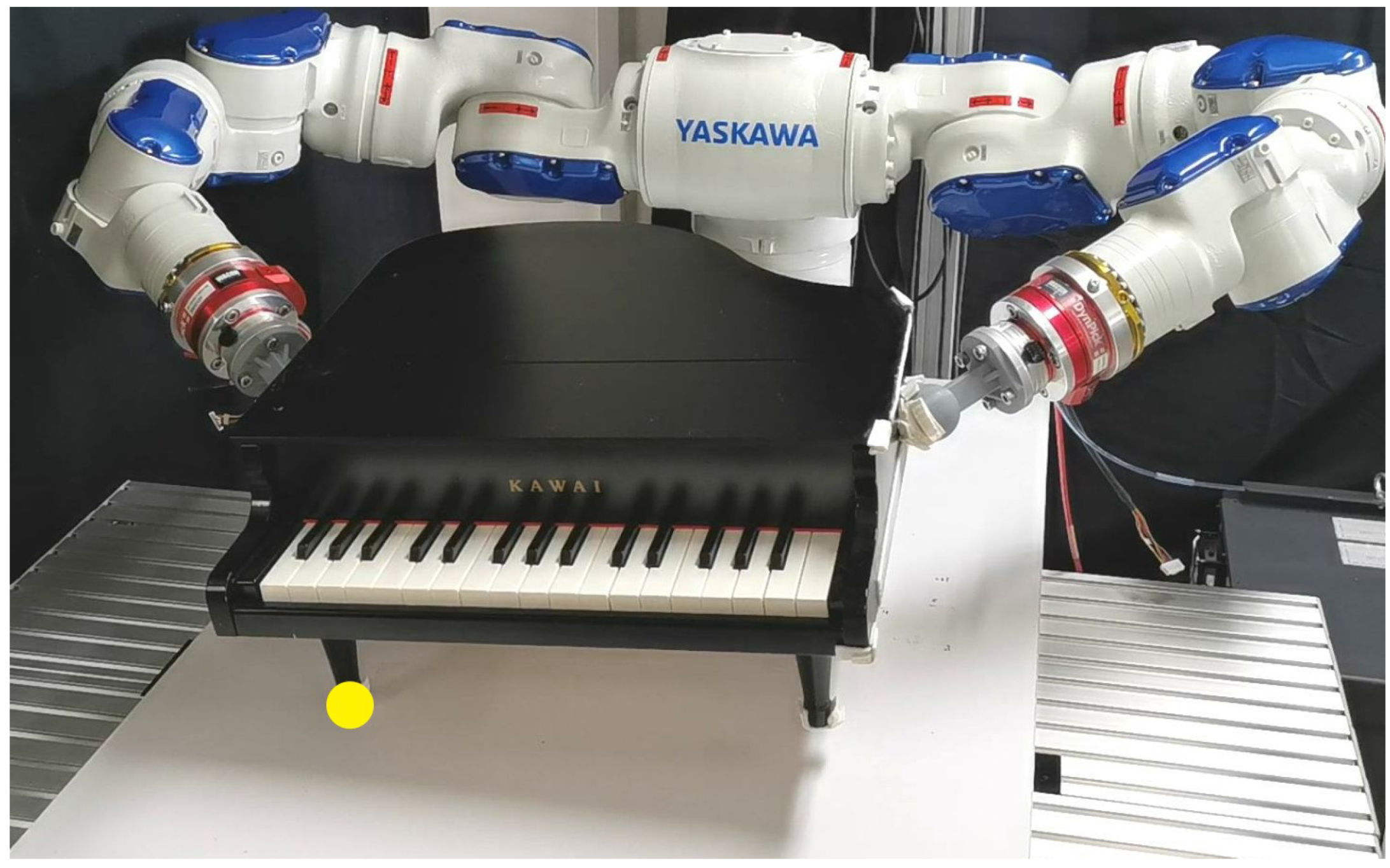
Humans often manipulate large and heavy objects utilizing the contact of the object with environment. Although robotic manipulation of general-shaped large and heavy objects is challenging, we aim to realize a robot manipulating such objects by effectively utilizing the contact of the object with a table (Figure 1). Among the manipulation styles using contact with a table, pivoting refers to the style of inclining and rotating an object on its vertex. Pivoting enables a robot to manipulate a bulky object with a relatively small manipulating force because the robot does not need to lift the object [1]. Moreover, the pivoting gait, which is a manipulation style, enables a robot to move an object by pivoting it multiple times by changing its rotational vertex. In addition, to start the pivoting gait from the designated initial pose of the object, a robot may once tumble the object by rotating it on its edge.
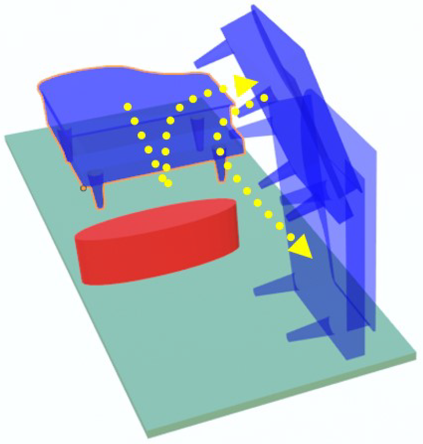
Pivoting gait has been explored for moving a simple box-shaped object [2,3]; however, this study aims to realize the robotic manipulation of a general-shaped object by combining pivoting, tumbling, and regrasping (Figure 2). Let us consider the example shown in Figure 3, where a robot moves a blue-colored object to the designated location on a table, with avoiding an obstacle (red colored). In this case, the robot first tumbles the object to an upright posture and then passes through the narrow passage using the pivoting gait. For realizing such combined manipulation, we need to determine the object face required to contact with table and the grasping pose of the object. In addition, a robot may change the grasping pose multiple times, and such changes of the grasping pose are referred as regrasping.
Our proposed planner comprises offline and online phases. In the offline phase, we first preprocess the mesh model of a general-shaped object clustered into superimposed segments [4] in order to determine the object’s contact surface with table and the contact surfaces with the end-effectors (EEFs). In the online phase, we propose a hierarchical motion planning method to determine the motion of both the object and the robot. Hierarchical planning includes task level planning and motion level planning. In the task level, we sample the object configurations on the table considering the kinematic constraints of pivoting and tumbling. At this level, the planner constructs a graph, where each node in the graph represents an object pose and a grasp configuration, and each edge in the graph indicates a primitive motion to transform the object poses or grasp configurations. The purpose of primitive motion is to realize either pivoting, tumbling, or regrasping. On the other hand, in the motion level, the robotic manipulation motions are generated. Here, the pivoting and tumbling motions are generated by predicting the object’s future dynamics using model predictive control (MPC), considering the kinematic constraints for maintaining contact with the environment.
Furthermore, this study expands the feasible object poses used in motion planning to both stable placements (SP) and unstable placements (USP). Here, SP indicates that the vertical projection of the object’s center of mass (CoM) is included in the object’s supporting area. The robot can easily regrasp the object in SP. On the other hand, in USP, a robot can manipulate an object within a limited support area, which offers more choice for avoiding collision in a narrow space. Despite this advantage, it is difficult to regrasp the object in USP because USP not only requires contact with the environment but also contact with the EEFs. If contact between the object and the EEFs is lost during USP, the object will fall. To solve this problem, the two EEFs sequentially change the contact point position, i.e., the left EEF moves to the desired position while the right EEF maintains contact with the object and vice versa.
The contributions of this work are as follows:
- A manipulation plan for pivoting a general-shaped object is proposed;
- Multiple motions, including tumbling, pivoting, and regrasping, are combined to better manipulate the object;
- Pivoting gait is planned in both SP and USP.
This reminder of this paper is organized as follows. Section 2 reviews the related work. Section 3 provides an overview of the proposed method. The required preprocessing of the object model to manipulate a general-shaped object is presented in Section 4. Section 5 introduces the manipulation planning design. It describes the sampling of the object configurations and the design of primitive motions, such as pivoting, regrasping, tumbling, which are combined into a graph. The performed simulation and experiments are detailed in Section 6. Finally, Section 7 summarizes the results and discusses the future work.
2. Related Works
2.1. Non-Prehensile Manipulation
The non-prehensile manipulation allows a robot to manipulate an object without firmly grasping it by taking advantage of contact with environment [5]. Examples of non-prehensile manipulation include pushing [6], tumbling [7], scooping [8], tilting [9], throwing [10], catching [11], batting [12], sliding [13] and pivoting [14].
Pivoting is efficient for manipulating heavy objects because the weight of the object is mostly supported by the table. Aiyama et al. [15] first proposed the manipulation of a heavy object by pivoting. Doshi et al. [16] and Raessa et al. [17] proposed motion planners to reorient an object by pivoting. Yoshida et al. [18,19] proposed a motion planner planning an object path during the pivoting gait. Shi et al. [20] proposed a tumbling motion planner. In addition, there have been some research on motion planning combining the pivoting gait with other manipulation styles. Fakhari et al. [21] proposed the manipulation planner combining the pivoting gait with tumbling. Murooka et al. [22,23] combined pivoting, pushing and tumbling. In all the above mentioned works, the pivoting gait was planned for a simple box shaped objects. On the other hand, this is a first trial on planning the motion of a general shaped object by combining pivoting, tumbling and regrasping. In addition, our planner considers both SP and USP to efficiently manipulate an object.
2.2. Regrasp Planning
There are several studies on the manipulation planner with regrasping an object [24,25,26,27,28,29]. Berenson et al. [30], and Bouyamane et al. [31] presented regrasp planners with a change in contact state between the object and the environment. Harada et al. [32] proposed a regrasp planning for dual-arm robots. Hayashi et al. [33] implemented manipulation planning to wrap-up fabric by incorporating two robot arms with regrasping. Wan et al. [34] proposed manipulation planning, which determines a sequence of dual-arm robot motion, to reorient an object with regrasping.
2.3. Grasp Planning
The grasp planning searches for a grasping pose of an object satisfying the force/form closure [35,36,37,38] or grasp stability condition [39,40,41]. In many regrasp planner, multiple grasping poses are calculated by using a grasp planner [4,42,43], before executing the motion planner. Then, a robot regrasps an object by switching among multiple grasping poses. To provide steady grasps, many elements must be considered, such as contact zones, object surface curvatures, mechanics of robot hands, and so on [44,45,46,47,48]. For two-fingered robot gripper, Jones et al. [49] and Wolter et al. [50] proposed grasp planners. Surface segmentation was used to determine the grasping points for a parallel-jaw gripper [42,51]. This study uses grasp planners for a parallel-jaw gripper [4] to determine the contact points on a general-shaped object manipulated by a dual-arm manipulator with ball-shaped EEFs. Cooperating two manipulators with the EEFs enables a robot to grasp a large object which may be too large for a gripper to grasp.
3. Steps of the Proposed Motion Planner
In this study, we assume that the 3D shape of the object is given. In addition, we assume that a dual-arm robot with ball-shaped EEFs manipulates the object at two contact points. To manipulate the object to the target pose, a hierarchical manipulation planner is built at the task and motion levels, which outputs the planned motions. The proposed motion planner is designed according to the following steps:
- Before executing the motion planner, the 3D model of the target object is analyzed to obtain the information necessary for the manipulation planner.This information includes the potential rotational vertices used for pivoting, edges used for tumbling, base surfaces for stably contacting the table, and the contact points between the object and EEFs;
- Task level planning then is performed. We discretize the object poses on a table. The object configurations along with their grasp configurations are saved in the graph nodes. In this phase, we consider object poses in both SP and USP;
- Finally, in motion level planning, primitive motions, such as pivoting, tumbling, and regrasping, are planned for moving the object to the target location.In the motion level, the designed motions include pivoting, tumbling, and regrasping. MPC is implemented to generate the motions because it can find the motions required for maintaining contact between the object and environment. If we cannot find any feasible motion in this level, we go back to the task level planning.
4. Object Model Analysis
To manipulate a general-shaped object, we preprocess its 3D-shape model and obtain the necessary information for manipulation planning. We aim to determine the following:
- A set of object vertices, which are the potential rotational vertices during pivoting;
- A set of object edges, which are the potential rotational edges during tumbling;
- A set of stable object placements;
- A set of grasp configurations for the dual-arm manipulator.
Superimposed segments are implemented when preprocessing the 3D-shape model of the object [4]. These segments often generate numerous grasp configurations. However, as numerous grasp configurations increase the calculation load of the manipulation planner, we reduce the number of grasp configurations by checking the collisions with the EEFs and evaluating the grasp stability, as described in the next subsection.
4.1. 3D Surface Model Processing for Grasp Planning
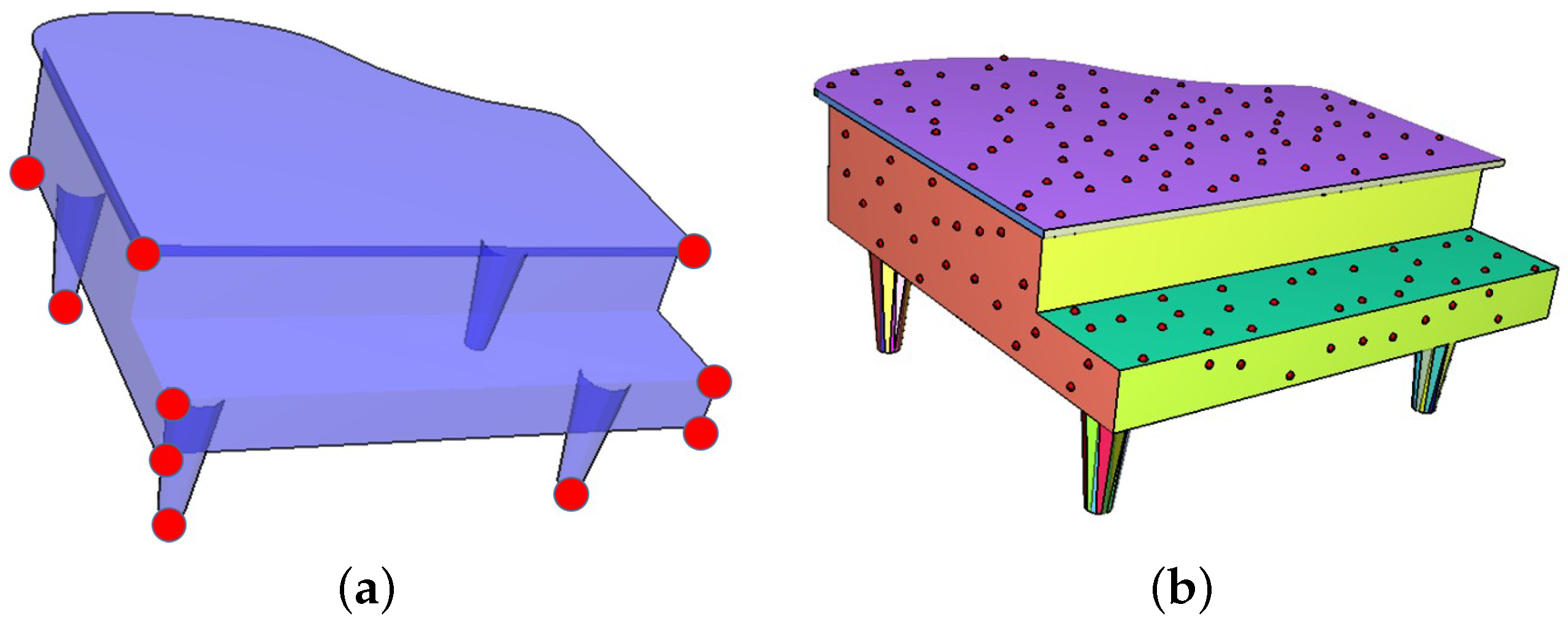
By calculating the convex hull of the model, its vertices, which are the potential rotational vertices used for pivoting, can be obtained (see Figure 4a). The rotational vertices are the supporting feet of objects during pivoting gait. In addition, the edges, which are the potential rotational edges used for tumbling, can be obtained from the convex hull.
Superimposed segments are implemented to process a mesh model for contact and grasp planning. It analyzes the object model by peeling it into facets where the facets are allowed to be overlapped by each other. In addition to superimposed segments, the ray-shooting method [52] and simple segments [42] can also be used for analyzing mesh models. The ray-shooting method samples a contact point on the mesh surface and finds the candidate counter contact point by shooting a ray from the sampled point along the reversed normal direction. The simple segments method is similar to the superimposed segments while the difference lies in if the overlapping of facets is considered. The comparison among the three methods has been researched in [4] which showed that the superimposed segments can find more grasps while the time cost of it is faster than that of the ray-shooting method and is not significantly worse than that of the simple segments.
In superimposed segments, given a triangulated CAD model [53], a seed triangle is initialized and is compared with the surrounding triangles by evaluating the differences between surface normals of triangles. If the difference is smaller than a threshold, the neighboring triangle is clustered into the same facet. Otherwise, a new facet based on the neighboring triangle is built. After dealing with the initial facet, the algorithm selects a new seed and repeats the clustering until all the triangles are scanned. As a result, a set of facets are generated by the superimposed segments, where each face can be a candidate contact surface with the table in SP. When placing an object on the table, we define SP if the vertical projection of the object’s CoM on the table is included in the support area. During SP, the robot is allowed to regrasp the object without influencing the stability of the object.
In addition, a set of contact points with the EEFs are computed by sampling the surface of the object model. To evenly distribute the contact points on the surface, sampling is initially performed over the entire surface. The sampled points are then repeatedly distributed as contact points on the superimposed facets. Further, some of the undesired sampling points are removed based on the following: (1) they are too close to the boundary of the facet, (2) they are close to each other, and (3) there is undesired collision between the object and the EEF. Examples of the sampled contact points are shown in Figure 4b.
4.2. Grasp Planning
In this study, a dual-arm robot with ball-shaped EEFs grasps the object at two contact points on nearly parallel facets with opposite contact normal vectors. By inspecting the candidate contact points on these facets, the planner computes the potential contact pairs. Among several grasping point candidates, we further analyze and select a feasible one for a given object pose. We check whether each grasp point candidate leads to collision among the links of the robot or between a link and the environment. In addition, we check whether the inverse kinematics (IK) is solvable and whether the grasp stability can be satisfied by checking the wrench cone generated by the contacts with the EEFs and the environment.
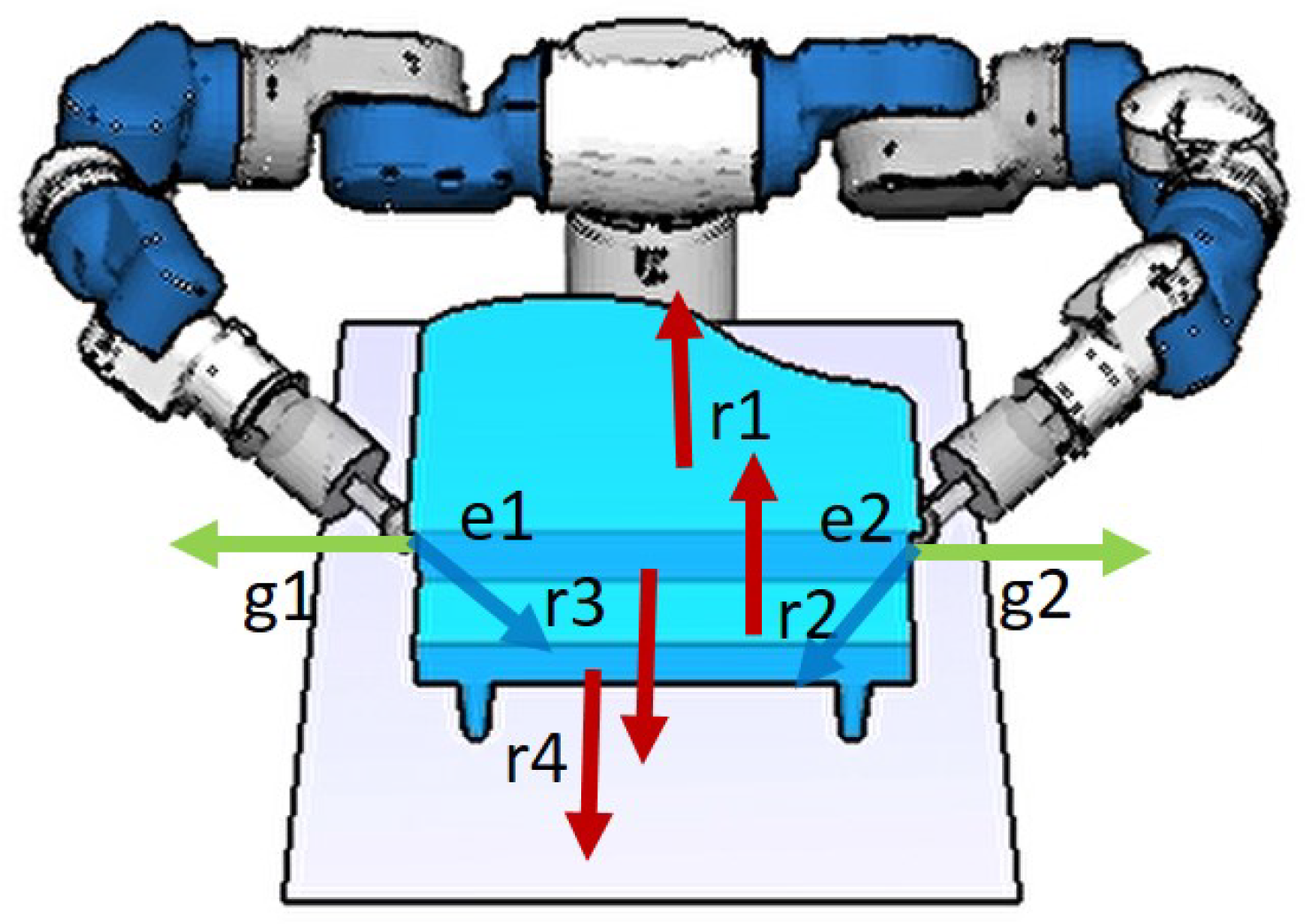
Figure 5 shows examples of the selected contact points. Given an object configuration, the surface normals of the object are compared with those of the table. The contact pairs on surfaces with normals r1 and r2 are removed because collision occurs between the EEF and table when the EEF contacts the bottom of the object. On the other hand, the surface normals of the object are also compared with the EEF’s rotational vector (e1 and e2). The contact pairs on surfaces with normals r3 and r4 are removed because they are too far to be reached by the EEF. As a result, only the contact pairs on the facets with surface normals g1 and g2 (green) remain.
4.3. Grasp Stability
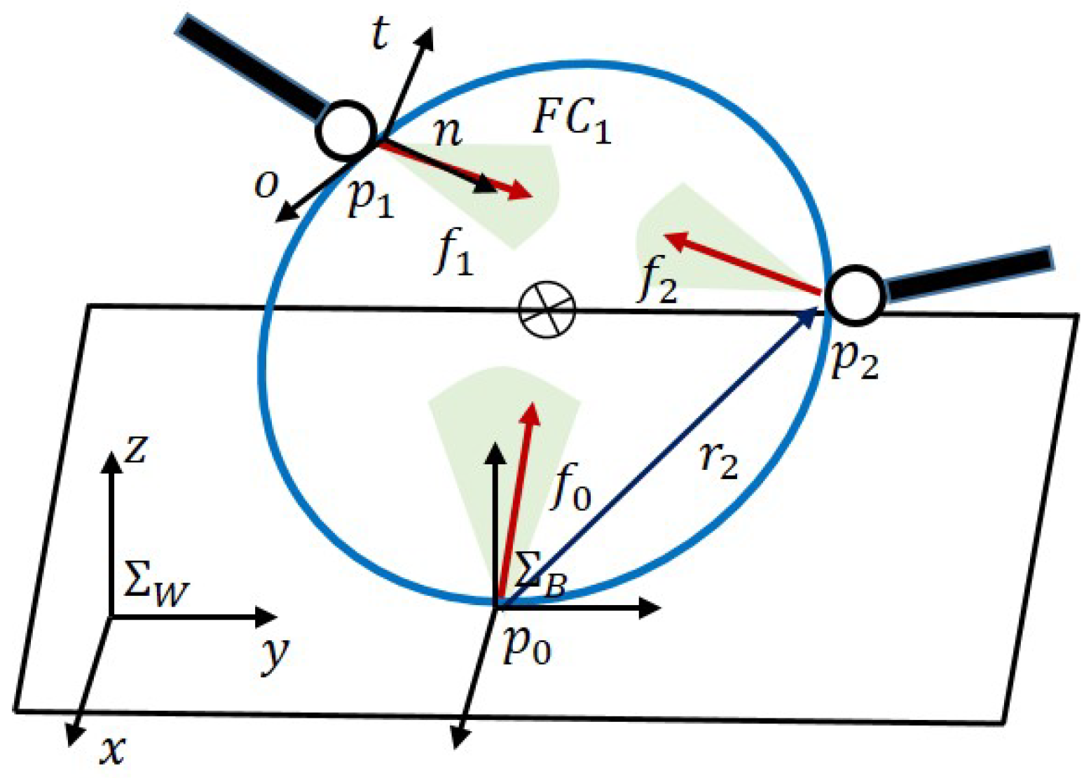
When pivoting, the object contacts two EEFs of the robot (see Figure 6). In addition, the object contacts the environment, such as the table. Considering these contacts, we can evaluate the grasp stability, which is the ability of an object to balance the external wrenches by the force vector f applied at each contact point:
where G denotes the grasp map that maps the contact forces to the total object wrench. If an object contacts the environment with a vertex, we define , where , , and are the force vectors applied by the environment and the two EEFs, respectively. On the other hand, if an object contacts the environment with two vertices during USP, one EEF will be sufficient to balance the external wrench. In this case, and are the force vectors applied by the environment, and is the force vector exerted by the EEF. This property allows us to regrasp the object in USP. Contact force , must lie within friction cone :
where is the friction coefficient at the i-th contact point. In this study, we approximate the friction cone using a six-sided polyhedral cone. By calculating the Minkowski sum [54] of the force at each contact point, we obtain the grasp wrench space (GWS, ) [55].
where indicates the wrench generated by the gravitational force. The stability s can be evaluated by calculating the minimum distance between the origin in the wrench space and the convex hull of the set . In this work, if the origin is inside of the GWS, the grasp is considered stable. In the physical world, the s indicates the ability to resist external wrenches and it can be calculated by:
Based on the grasp stability, we select the stable grasp configurations.
5. Hierarchical Manipulation Planning
We plan the motions to manipulate an object on which information is available. We propose hierarchical planning, which includes task and motion level planning. The manipulation planner constructs a graph. In task level planning, we design the discrete object poses on a table, which along the grasp poses are saved in the nodes. In motion level planning, we plan the motions for moving the object and changing the grasp configurations. Primitive motions, such as pivoting, tumbling, and regrasping, are represented by the edges of the graph. Further, given the initial and goal configuration of the object, we search the graph and find a motion sequence to manipulate the object to the goal position.
Different from previous planners [2,3,19], we consider tumbling and regrasping in addition to the pivoting gait. Moreover, we consider the SP and USP of the object. Object motion in USP allows object movement within a limited table area. However, the object may easily fall if the robot regrasps it in USP. To avoid this problem, we design the regrasping motion in USP, such that the robot sequentially changes the contact position of each EEF.
5.1. Task Level Planning
In task level planning, we sample the object poses on a table, and save information on the object configurations and the related grasp configurations in the nodes. The object poses are not sampled randomly on the table because pivoting includes a kinematic constraint that the object must be rotated around a fixed point on the table, which is also the object’s rotational vertex. In the graph, we sample new object poses with respect to the pivoting and tumbling motions (see Figure 7). In pivoting motion, we discretize the object pose when rotating about the vertical line including the object vertex. The rotation is discretized in intervals. We repeat such sampling for all the vertices in the current base surface. By sequentially changing the rotational vertices, the object can be moved through pivoting gait along a certain direction (see Figure 8).
To sample new object configurations by tumbling, the object is rotated around an object edge until the object moves from one SP to another (see Figure 2b and Figure 7). Tumbling enables a change in the support surface, which provides more choice in the path planning of the object, in case an obstacle is present (see Figure 3).
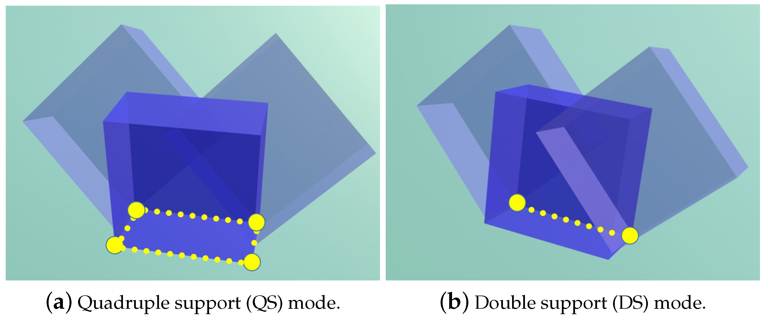
In this study, most of the object poses are designed in SP. However, within a limited table area, such as the boundary of the table, it is difficult to place the object in SP. For such an area, we sample the object pose in USP where an EEF of the robot assists in holding the object. To retain an object in USP, we check the grasp stability, discussed in Section 4.3, to select the contact points of the EEFs. Here, it is to be noted that sampling the object poses in USP corresponds to pivoting the object assuming the double support (DS) gait mode, as discussed in [3]. On the other hand, sampling the object poses in SP corresponds to pivoting the object assuming the quadruple support (QS) gait mode. Figure 9 shows the difference between the DS and QS gait modes. Refer [3] for the details on the DS and QS gait modes.
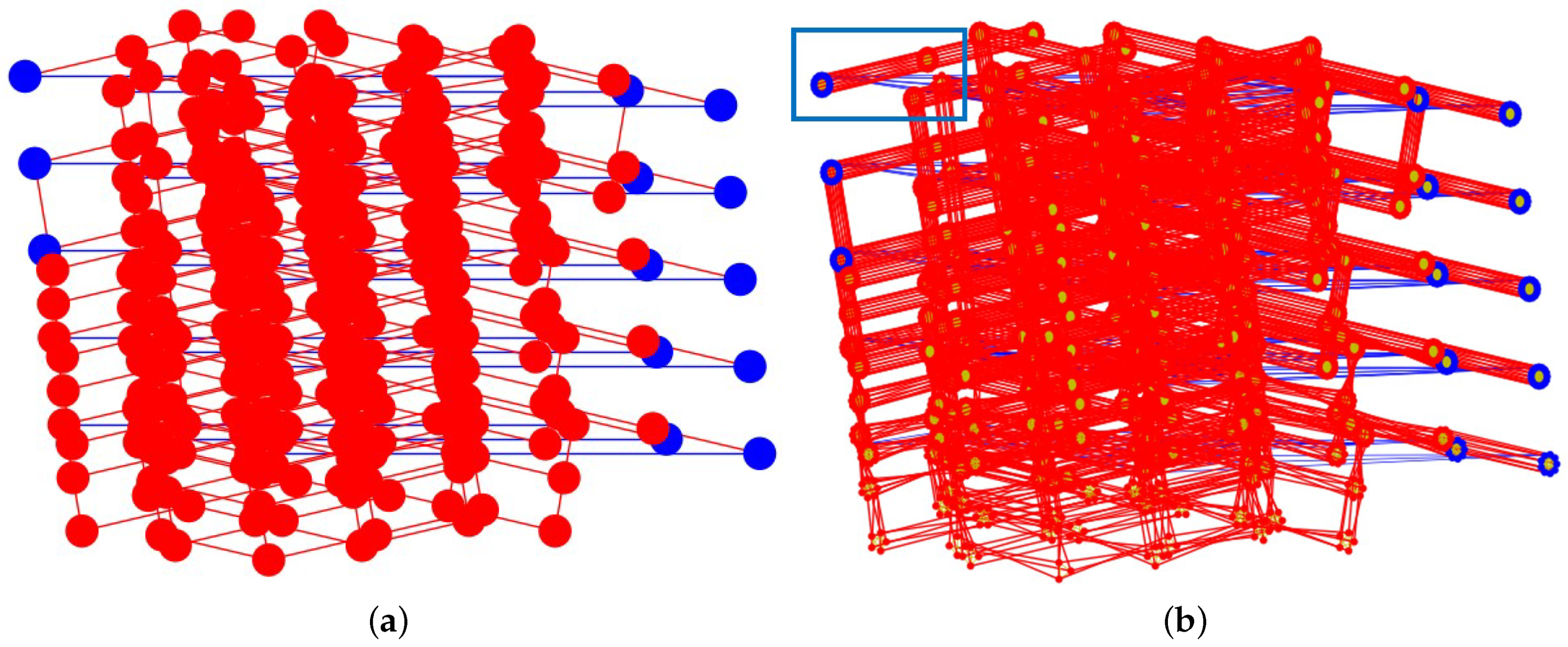
Figure 10a shows the sampled object poses on the table. Each node indicates an object pose; the red ones denote SP, whereas the blue ones denote USP. The red and blue edges indicate pivoting and tumbling motion, respectively. For better manipulation performance in the real physical world, we also evaluate the change in the angle between the EEF and the contact surface normal during pivoting motion.
Combining the corresponding grasp configurations with the object configuration, we can generate the graph shown in Figure 10b. In this graph, each node includes information on the grasp configurations and the object pose related to Figure 10a.
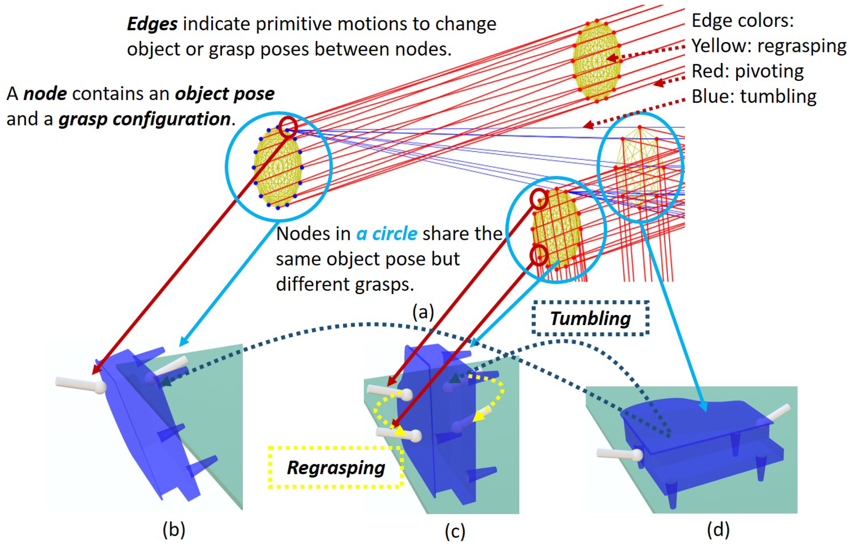
The detailed explanations of the graph are shown in Figure 11, where the blue rectangular part in Figure 10b is amplified. A node contains information on both an object and a grasp configuration. Nodes insides a light blue circle (which is drawn only for explanations in Figure 11 and is not included in the graph) indicate they share the same object pose but different grasp configurations. Three primitive motions are represented by edges where yellow, red, and blue edges imply regrasping, pivoting, and tumbling, respectively. The configurations saved in nodes can be transferred by the edges connecting them. For example, in Figure 11b, the grasp configurations of two nodes are changed by a yellow edge which implies regrasping. The design of SP and USP is also reflected in the graph where blue nodes indicate USP, see Figure 11b and red nodes indicate SP, see Figure 11c,d. What is more, there are fewer nodes within the right blue circle in (a) because there are fewer grasps as the contact surface in the current object pose is small, see Figure 11d.
5.2. Motion Level Planning
After sampling the object poses on the table and generating the corresponding grasps, the motions to move the object and change the grasp poses are generated in motion level planning. The primitive motions include the following: (i) pivoting motion, which is a transfer motion to change the object configuration without changing the grasps, (ii) tumbling motion, which includes both transfer and transit motions to rotate the object around one edge and change its base surface, and (iii) regrasping of an object in SP involving transit motion, which changes the grasp configurations without affecting the object configuration, and regrasping of an object in USP, which involves both transit and transfer motions.
5.2.1. Pivoting
Pivoting motion is designed by raising the object up on a vertex, rotating it around the vertex, and placing it down. A property of pivoting motion is that two object poses must share the same rotational vertex. Figure 8 displays 2D examples in which pivoting gait is used to move an object in the direction indicated by arrows.
In Figure 6, the contact point between the object and table is denoted by . Here, we assume point contact with friction at each contact point. Due to contact with table at a fixed vertex (), the object motion is constrained as follows:
Contact between the object and i-th EEF () is constrained as follows:
where S is a selection matrix that selects the linear velocity and transforms the linear and angular velocity from to . Details on the S and D matrices can be found in our previous work [3]. The object is accelerated by the force () applied by the two EEFs. The dynamic of the object’s rotational motion can be obtained as
where , , and where denotes the position vector of the object’s CoM. and indicate the mass and moment of inertia of the object, respectively. and indicate the angular velocity and angular acceleration of the object in frame , respectively.
In the motion level, the robot motions to move the object between the object poses designed in the nodes are generated by MPC with respect to the kinematics (5), (6), and the dynamic (7). Figure 12b depicts an example of the generated motions for pivoting a piano. In MPC, we define the state vector as where indicates the Euler angles of the object in and select the input vector as . During the object’s rotation on the vertex , the prediction of the state is obtained by,
where , and D are coefficient matrices defined as
where the matrix W transforms the angular velocity to the velocity of the Euler angles.
The future states and free variables appear in the prediction horizon () are defined as and , respectively. The MPC tracks a reference by solving the following optimization problem,
where and are the weights. is the reference trajectory of the object and it is provided by the object configuration saved in nodes of the graph. The first and the second terms in (11) evaluate the state error and the amount of the manipulating force of the EEF, respectively.
5.2.2. Tumbling and Regrasping
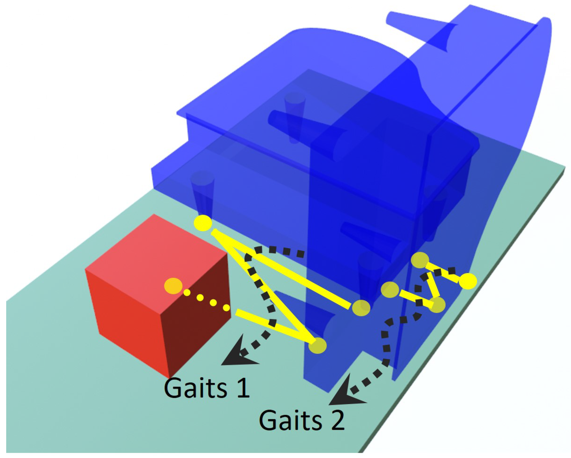
Changing the base surface of the object improves the obstacle avoidance performance. The object’s base surface is the support surface between the object and the table. The proposed method has better collision-avoidance capability since pivoting gait is performed with the combination of tumbling and regrasping. By tumbling, we can control the area of support polygon and it contributes to the case when a manipulated object passes through a narrow passage. In addition, by regrasping, we may avoid the collision between the robotic arms and the environment. An example of the object motion is shown in Figure 13, where the gaits 1 cannot avoid the collision with the red obstacle since the object is not tumbled. If the object is tumbled to the right as shown in the right of Figure 13, the supporting polygon can be changed. Such a change allows the object to be moved without colliding the obstacle by performing the gaits 2. Tumbling motion contributes to change the type of gaits adaptively according to the environment.
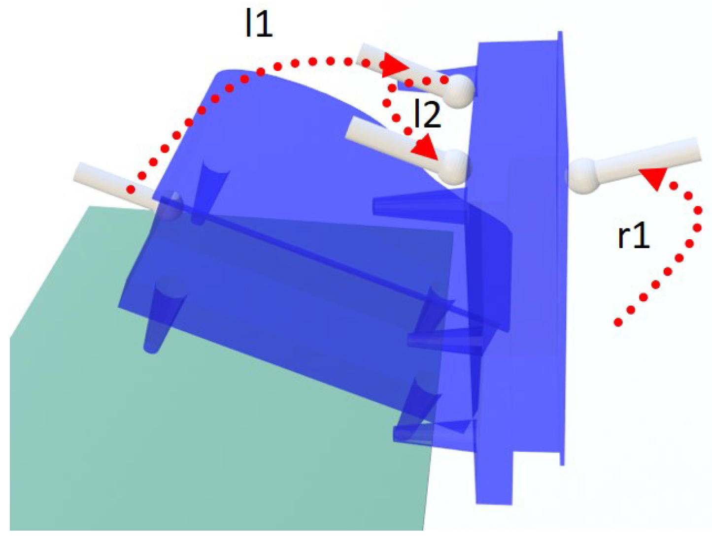
For changing the object’s base surface, we design tumbling motion, which is a special case of pivoting when the rotation passes through the object’s edge. Rotating an object up to SP is simple, where one EEF rotates the object around one edge (the line connecting the two supporting vertices) of the object until it moves to SP. The kinematics and dynamics of tumbling motion can be derived through minor modifications in (5)–(11). However, rotating an object up to USP is more complex. This is because to maintain an object in USP, the EEF must contact and hold the object, which leads to difficulty in changing the grasp poses. To solve this problem, we incorporate multiple arms to achieve regrasping by sequentially using different arms to contact the object. Figure 14 depicts a tumbling motion where the object is rotated to USP in the boundary of the table. If the right EEF does not contact the object, it will fall from the table. The tumbling motion is designed as follows: First, the left EEF contacts and rotates the piano (see motion l1). Meanwhile, the right EEF moves to the desired position, which is also the right EEF’s grasp pose for contacting the object in USP (see motion r1). The left EEF rotates the object until it contacts the right EEF. Next, the right EEF alone holds the object. The stability is evaluated by calculating the contact wrench of the contact between the right EEF and the object, as well as that between the object and table, as mentioned in Section 4.3. The left EEF then leaves the object and moves to the desired grasp configuration (see motion l2). Compared to regrasping with a gripper, which can only regrasp an object in SP, a multi-arm robot can regrasp an object in both SP and USP.
5.3. Graph Searching
Given the initial and goal poses of the object, grasps of these object poses can be determined by data provided by object analysis introduced in Section 4. Then, we look for the same object and grasp configurations that are embedded in nodes of the graph. If the new object poses and their grasp configurations can not be found in the graph, new nodes will be created and be connected with the graph. The reachability of new nodes can be guaranteed by the controllability of pivoting motion [18], which proved that a sequence of three pivoting motions can move the object to an arbitrary object configuration with the same base surface in the neighborhood.
Weights are manually assigned to edges in the graph. As the object can be efficiently moved by pivoting and we expect the robot finishes the placement of the object quickly, we set the weight of edges representing pivoting to a small value 0.1. The weight of edges indicating regrasping is set to 0.5 and the weight of edges indicating tumbling is set t 1. A relative large weight is designed to edges related to tumbling because the tumbling is mainly designed for changing the object’s supporting base instead of moving the object. Knowing the initial and goal configurations, we search the weighted graph to find a path. A solution path includes sequences of discrete object and grasp configurations. Intermediate configurations are added to ensure a smooth motion during pivoting and tumbling by the MPC introduced in Section 5.2. In a lower-level motion planning, we use rapidly exploring random tree (RRT) to sample the space considering grasp configurations. At this level, if configurations with feasible inverse kinematics and obstacle clearance cannot be found, we go back to the graph, remove certain nodes and edges which caused the problem and re-search the graph for a new path.
6. Simulation and Experiments
In this study, the target object is a toy piano sized 0.425 × 0.45 × 0.205 m with a weight of 3.1 kg. The piano is placed on a table, which is in front of the robot, and the size of the table surface is 0.9 × 0.6 m. We use a dual-arm Yaskawa Motoman SDA5F robot to manipulate the object. The two EEFs of the robot are the same and ball-shaped. They are produced by a 3D printer where the diameter of the ball is 4 cm. In addition, to increase the friction between the EEFs and the object, anti-slip stickers are added to the tip of EEFs.
6.1. Object Analysis
A mesh piano model is processed by the superimposed segments offline. The computational costs and the results of the analysis of the mesh model are shown in Table 1. The results are obtained by executing the process on a desktop PC where the CPU is Intel Core i7-9700K @ 3.60 GHZ and a memory in size of 8 GB. The program is performed using Python 3.6.
The number of faces of the object generated by the superimposed segments is 262 which is large. This is because curvatures of the object, for example, the legs of the piano, can be separated to many faces, see Figure 4b. It is a time-consuming process to refine samples and plan contact pairs where bad samples are removed due to the rules mentioned in Section 4.1 and collision checking between the EEFs and the object. The time cost is reasonable because a mesh-to-mesh collision detection is implemented. After the refinement, contact pairs are created based on the remaining samples.
Contact pairs under a given object configuration can be refined by grasp stability and collision checking between the EEFs and the environment by the rules discussed in Section 4.2 and Section 4.3. In Figure 10b, the total number of sampled object configurations is 310 and the number of feasible grasp configurations after the refinement is 4207 where the process of the refinement costed 9.362 s. The time cost of the refinement is relatively high but acceptable since we only need to do it once and offline. If the refinement is not implemented, the evaluation of the grasp stability will be performed 33,170 () times and cost over one minute.
6.2. Simulation
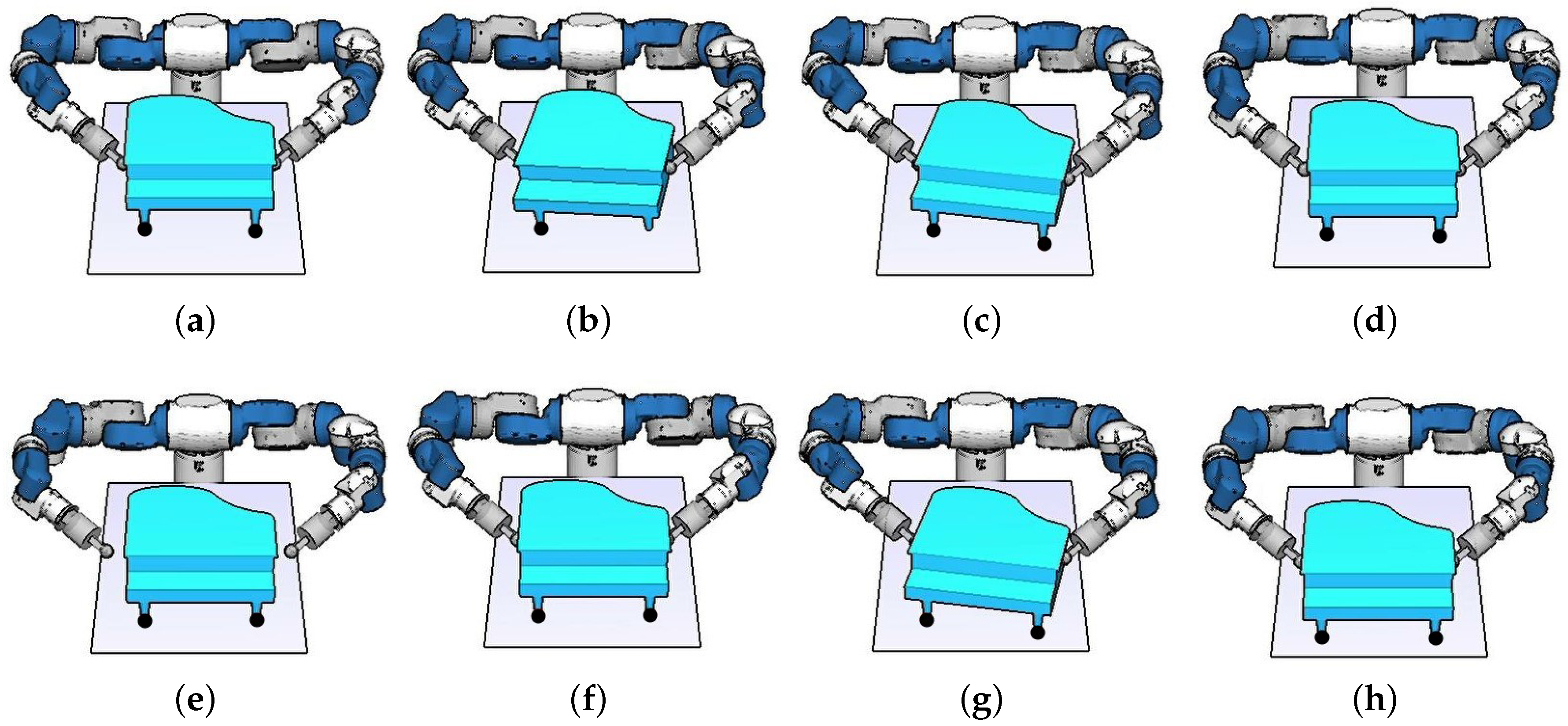
In the simulation, the target is to move the piano to the goal pose, which is far from the robot (see Figure 15). The robot first grasps the piano placed on the table (see Figure 15a). Further, it pivots the piano around one vertex under the front right leg (see Figure 15b). Here, we define the left and right sides of the object and those of the robot according to the view from the robot. In Figure 15c, the piano is placed on the table and the rotational vertex is changed from right to left. Then, through pivoting motion, the piano is placed in the pose shown in Figure 15d. Note that both arms of the robot are close to their kinematic limits and the robot cannot further move the object forward. However, the robot changes its grasp configuration and grasps the rear of the object (see Figure 15e,f). Thereby, the robot can pivot the piano to move it forward and successfully place it in the goal position (see Figure 15g,h). By changing the grasp configuration, the piano is moved forward by as much as 12.5 cm (see Figure 15d,h).
This simulation demonstrates that regrasping motion extends the scope of feasible placements of the object manipulated by the robot.
6.3. Experiment 1: Pivoting Gait
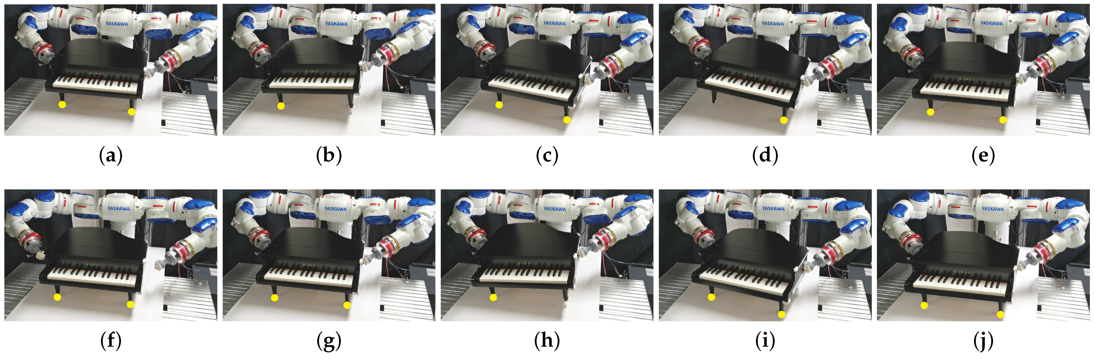
In the first experiment, we perform the simulated pivoting gait in a real scenario. The inputs are the initial and target poses of the piano. The system automatically plans the grasp, pivoting motion, and regrasping motion. Figure 16 depicts the experimental process. The robot first grasps the piano (see Figure 16a) and pivots it around the right (from the robot view) rotational vertex (see Figure 16b). Further, the robot changes the rotational vertex to the left (see Figure 16c) and pivots the piano (see Figure 16d,e). In Figure 16e, both the arms are close to the limit of the robot workspace; hence, the robot cannot further move the piano forward. Pivoting gaits generated by the graph MPC [3] faces such limitations and the object cannot be placed in the target location. To solve this problem, regrasping is planned in this work and the robot changes the grasp poses to grasp the rear part of the object (see Figure 16f,g) and successfully pivots the piano to the target pose (see Figure 16h–j. Table 2 compares the performances of two methods where only the proposed planner can generate motions to move the object to the target location.
In the experiment, after moving the piano a few steps, the robot cannot further move the object with the initial grasp poses because of the robot workspace. To continue moving the object, the robot finds a new grasp configuration, regrasps the piano, and manipulates it to the target location. Compared with the pivoting gaits generated by the graph MPC [3], the regrasping motion enables further motion of the object by as much as 12.5 cm along the x-axis.
6.4. Experiment 2: Object Orientation
Experiment 2 tests a combination of regrasping and pivoting during the rotation of the piano around the z-axis in the world frame (see Figure 17). The initial pose of the piano is shown in Figure 17a and the support vertices are marked as yellow dots. The robot grasps the piano, pivots it around one of its support vertices, and places it down in a pose where a rotation of −45 degrees in the z-axis is performed (see Figure 17a–c). Further, the robot changes the grasp poses to different contact surfaces as depicted in Figure 17d,e to avoid self-collision of the robot and maintain the EEF in a reachable pose. After regrasping, the robot rotates the piano by another −45 degrees around the z-axis and places it down (see Figure 17f). In Figure 17g,h, a new regrasping motion is performed after which the robot pivots the piano to the target pose (see Figure 17i,j).
Experiment 2 shows that to perform a relatively large change in the object orientation, the robot needs to contact different surfaces of the object; with a combination of regrasping and pivoting, the robot successfully manipulates the object to the target pose.
6.5. Experiment 3: Obstacle Avoidance
In the third experiment, the robot moves the piano to the target pose considering the environment where an obstacle exists and the limited support surface (see Figure 18). Different from the sheering method [2], which cannot find a feasible path to avoid collision, changing the object’s base surface by tumbling can realize better collision avoidance between the object and the obstacle. Moreover, the USP design allows the robot to manipulate the object within a narrow support surface without falling.
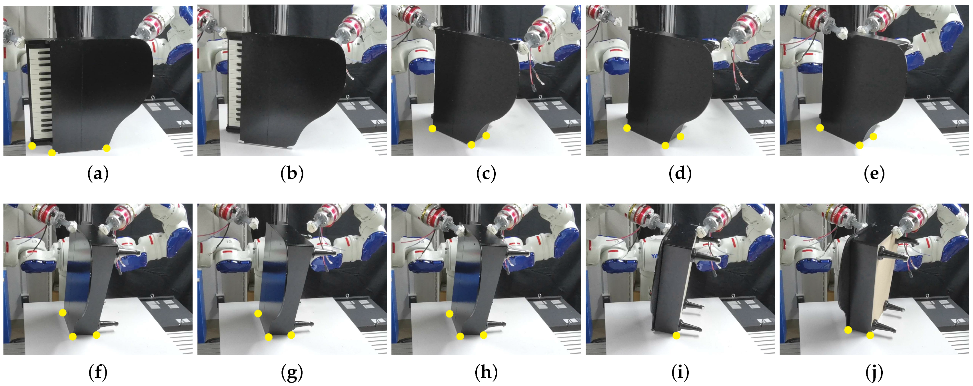
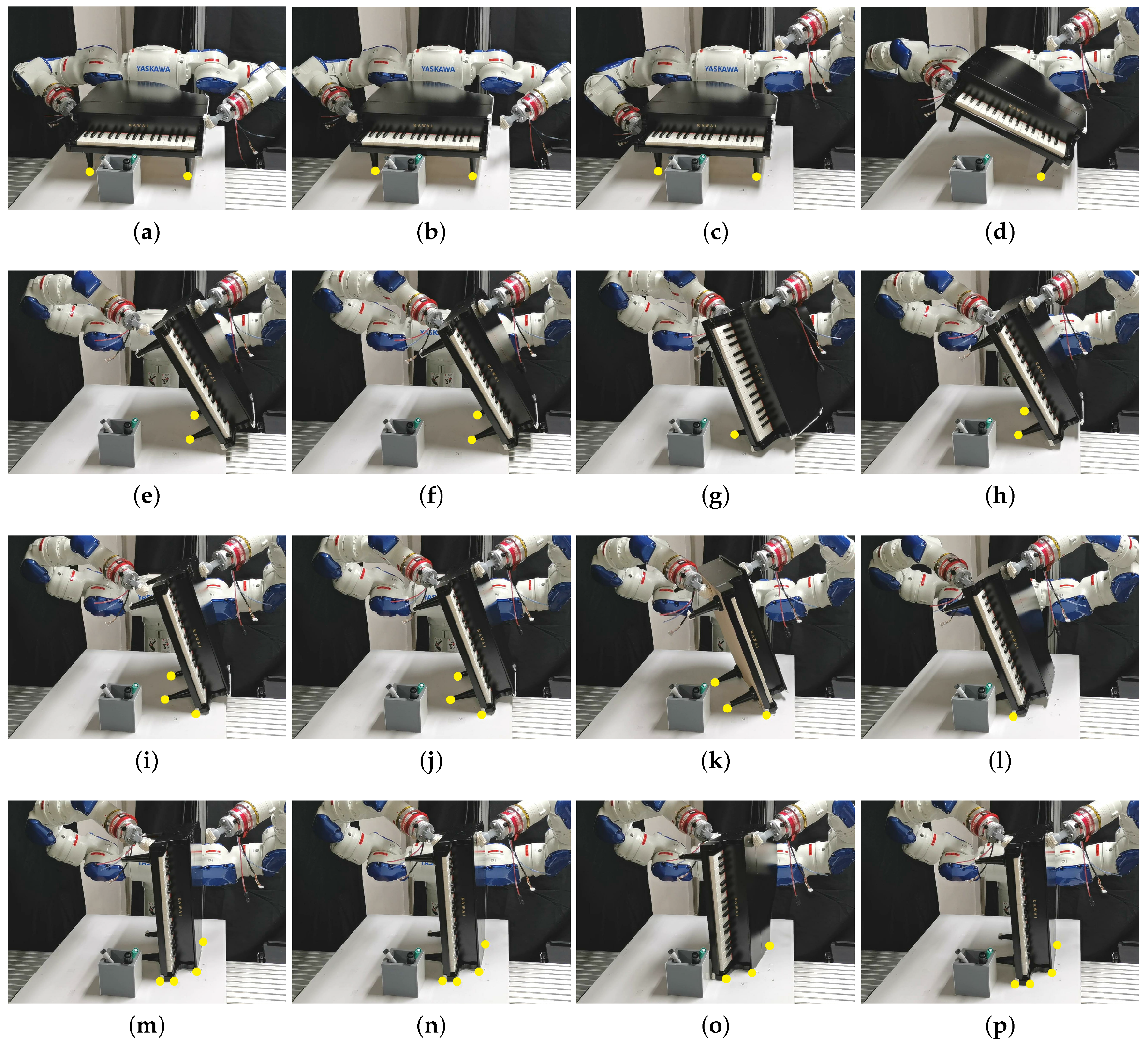
A grey pen holder is placed in front of the piano as an obstacle (see Figure 18a). The poses of the obstacle and the piano are input to the system. As the obstacle is very close to the piano, the piano cannot avoid collision by performing the pivoting gait using the sheering method. Therefore, the robot tries to tumble the piano. The right EEF moves to a new grasp configuration and prepares for the tumbling motion, whereas the left EEF moves to the planned grasp configuration preparing to catch and hold the object after rotation (see Figure 18b,c). The robot utilizes the right EEF to rotate the piano (see Figure 18d). Once the piano is in contact with the left EEF, the right EEF leaves the piano and moves to a new grasp pose (see Figure 18e,f). As a result, after the rotation, regrasping is performed by sequentially incorporating the right and left EEFs to hold the piano, which is an advantage of the dual-arm robot. Note that as the supporting table is narrow and the piano is near the table boundary, sufficient space is not available for the piano to be placed in SP and the left EEF is used to keep the piano in USP. For example, if the left EEF does not hold the piano, the piano will fall from the table (see Figure 18e). The USP design allows the robot to manipulate the object within a limited support space. Subsequently, the robot performs the pivoting gait designed for the USP, which is the DS gait mode (see Figure 18g,h). The robot places the piano in SP when there is sufficient space on the table, and then changes the grasp configurations (see Figure 18i,j). After regrasping, the robot pivots the piano for two steps along the y-direction (see Figure 18k,l) and then tumbles the piano to change the support surface through the right EEF (see Figure 18m). Finally, the robot regrasps the object and pivots it for two steps along the x-direction, and places it at the target location (see Figure 18n–p). During the entire process, there is no collision between the object and the obstacle.
Experiment 3 demonstrates that changing the object’s base surface improves the collision avoidance performance in pivoting gait. In addition, the USP design enables the robot to move the object within a limited support space. Moreover, the multiple arms incorporated to sequentially contact the object achieve regrasping in USP.
7. Conclusions
In this study, we proposed a manipulation plan for moving a general-shaped large object. With superimposed segments, the object model was first analyzed, and the contact between the object and EEFs, as well as that between the object and environment were determined. Utilizing the object’s contact with the environment, we realized the manipulation of a bulky object through pivoting, tumbling, and regrasping. In the plan, the object configurations in both SP and USP were considered, enabling the robot to manipulate the object within a limited support area. The proposed approach takes advantage of the kinematic, dynamic, and gait modes of the pivoting gait published in our previous work [3], which is related to motion planning for moving the object in both SP and USP. In this study, this pivoting gait is further improved by combining regrasping and tumbling. The efficiency of the proposed method was demonstrated through experiments in which the robot moved an object to the goal configuration, avoiding the kinematic limits of the robot arms and exhibiting better collision avoidance performing compared to those reported in prior works. The proposed approach can be employed to automate the manipulation of large objects by dual-arm manipulators. In future, we intend to manipulate more complex-shaped objects, using one EEF to perform pivoting, and planning motions in more complex environment for testing the planner’s performance. Quantitative analysis based on computational costs, stability, number of gaits, tumbles and regrasps to finish a task will be researched.
Author Contributions
The authors’ contributions are reported as follows: Original concept, A.Z. and K.H.; Methodology, A.Z., K.K., W.W. and K.H.; Software implementation, A.Z. and W.W.; Technical implementation, A.Z.; Writing—Original Draft Preparation, A.Z.; Writing—Review and Editing, A.Z. and K.H.; Supervision, K.K., W.W. and K.H.; Project Administration, K.H. All authors have read and agreed to the published version of the manuscript.
Funding
This research received no external funding.
Conflicts of Interest
The authors declare no conflict of interest.
References
- Yoshida, E.; Blazevic, P.; Hugel, V.; Yokoi, K.; Harada, K. Pivoting a large object: Whole-body manipulation by a humanoid robot. Appl. Bionics Biomech. 2006, 3, 227–235. [Google Scholar] [CrossRef]
- Yoshida, E.; Poirier, M.; Laumond, J.P.; Kanoun, O.; Lamiraux, F.; Alami, R.; Yokoi, K. Pivoting based manipulation by a humanoid robot. Auton. Robot. 2010, 28, 77–88. [Google Scholar] [CrossRef]
- Zhang, A.; Koyama, K.; Wan, W.; Harada, K. Controlling Pivoting Gait Using Graph Model Predictive Control. IEEE Access 2021, 9, 73757–73770. [Google Scholar] [CrossRef]
- Wan, W.; Harada, K.; Kanehiro, F. Planning Grasps With Suction Cups and Parallel Grippers Using Superimposed Segmentation of Object Meshes. IEEE Trans. Robot. 2020, 37, 166–184. [Google Scholar] [CrossRef]
- Lynch, K.M.; Mason, M.T. Dynamic nonprehensile manipulation: Controllability, planning, and experiments. Int. J. Robot. Res. 1999, 18, 64–92. [Google Scholar] [CrossRef]
- Chavan-Dafle, N.; Holladay, R.; Rodriguez, A. Planar in-hand manipulation via motion cones. Int. J. Robot. Res. 2020, 39, 163–182. [Google Scholar] [CrossRef] [Green Version]
- Sawasaki, N.; INOUE, H. Tumbling objects using a multi-fingered robot. J. Robot. Soc. Jpn. 1991, 9, 560–571. [Google Scholar] [CrossRef]
- Trinkle, J.C. On the stability and instantaneous velocity of grasped frictionless objects. IEEE Trans. Robot. Autom. 1992, 8, 560–572. [Google Scholar] [CrossRef]
- Erdmann, M.A.; Mason, M.T. An exploration of sensorless manipulation. IEEE J. Robot. Autom. 1988, 4, 369–379. [Google Scholar] [CrossRef] [Green Version]
- Satici, A.C.; Ruggiero, F.; Lippiello, V.; Siciliano, B. A coordinate-free framework for robotic pizza tossing and catching. In Proceedings of the 2016 IEEE International Conference on Robotics and Automation (ICRA), Stockholm, Sweden, 16–21 May 2016; pp. 3932–3939. [Google Scholar]
- Cigliano, P.; Lippiello, V.; Ruggiero, F.; Siciliano, B. Robotic ball catching with an eye-in-hand single-camera system. IEEE Trans. Control Syst. Technol. 2015, 23, 1657–1671. [Google Scholar] [CrossRef] [Green Version]
- Sun, Y.; Xiong, R.; Zhu, Q.; Wu, J.; Chu, J. Balance motion generation for a humanoid robot playing table tennis. In Proceedings of the 2011 11th IEEE-RAS International Conference on Humanoid Robots, Bled, Slovenia, 26–28 October 2011; pp. 19–25. [Google Scholar]
- Ramirez-Alpizar, I.G.; Higashimori, M.; Kaneko, M.; Tsai, C.H.; Kao, I. Nonprehensile dynamic manipulation of a sheet-like viscoelastic object. In Proceedings of the 2011 IEEE International Conference on Robotics and Automation, Shanghai, China, 9–13 May 2011; pp. 5103–5108. [Google Scholar]
- Hou, Y.; Jia, Z.; Mason, M.T. Fast planning for 3d any-pose-reorienting using pivoting. In Proceedings of the 2018 IEEE International Conference on Robotics and Automation (ICRA), Brisbane, Australia, 21–25 May 2018; pp. 1631–1638. [Google Scholar]
- Aiyama, Y.; Inaba, M.; Inoue, H. Pivoting: A new method of graspless manipulation of object by robot fingers. In Proceedings of the 1993 IEEE/RSJ International Conference on Intelligent Robots and Systems (IROS’93), Yokohama, Japan, 26–30 July 1993; Volume 1, pp. 136–143. [Google Scholar]
- Doshi, N.; Hogan, F.R.; Rodriguez, A. Hybrid differential dynamic programming for planar manipulation primitives. In Proceedings of the 2020 IEEE International Conference on Robotics and Automation (ICRA), Paris, France, 31 May 31–31 August 2020; pp. 6759–6765. [Google Scholar]
- Raessa, M.; Wan, W.; Harada, K. Planning to repose long and heavy objects considering a combination of regrasp and constrained drooping. Assem. Autom. 2021. [Google Scholar] [CrossRef]
- Yoshida, E.; Poirier, M.; Laumond, J.P.; Alami, R.; Yokoi, K. Pivoting based manipulation by humanoids: A controllability analysis. In Proceedings of the 2007 IEEE/RSJ International Conference on Intelligent Robots and Systems, San Diego, CA, USA, 29 October–2 November 2007; pp. 1130–1135. [Google Scholar]
- Yoshida, E.; Poirier, M.; Laumond, J.P.; Kanoun, O.; Lamiraux, F.; Alami, R.; Yokoi, K. Regrasp planning for pivoting manipulation by a humanoid robot. In Proceedings of the 2009 IEEE International Conference on Robotics and Automation, Kobe, Japan, 12–17 May 2009; pp. 2467–2472. [Google Scholar]
- Shi, F.; Zhao, M.; Murooka, M.; Okada, K.; Inaba, M. Aerial Regrasping: Pivoting with Transformable Multilink Aerial Robot. In Proceedings of the 2020 IEEE International Conference on Robotics and Automation (ICRA), Paris, France, 31 May–31 August 2020; pp. 200–207. [Google Scholar]
- Fakhari, A.; Patankar, A.; Chakraborty, N. Motion and Force Planning for Manipulating Heavy Objects by Pivoting. arXiv 2020, arXiv:2012.06022. [Google Scholar]
- Murooka, M.; Nozawa, S.; Bando, M.; Yanokura, I.; Okada, K.; Inaba, M. Simultaneous planning and estimation based on physics reasoning in robot manipulation. In Proceedings of the 2018 IEEE International Conference on Robotics and Automation (ICRA), Brisbane, Australia, 21–25 May 2018; pp. 3137–3144. [Google Scholar]
- Murooka, M.; Ueda, R.; Nozawa, S.; Kakiuchi, Y.; Okada, K.; Inaba, M. Global planning of whole-body manipulation by humanoid robot based on transition graph of object motion and contact switching. Adv. Robot. 2017, 31, 322–340. [Google Scholar] [CrossRef]
- Siméon, T.; Laumond, J.P.; Cortés, J.; Sahbani, A. Manipulation planning with probabilistic roadmaps. Int. J. Robot. Res. 2004, 23, 729–746. [Google Scholar] [CrossRef] [Green Version]
- Lozano-Pérez, T.; Kaelbling, L.P. A constraint-based method for solving sequential manipulation planning problems. In Proceedings of the 2014 IEEE/RSJ International Conference on Intelligent Robots and Systems, Chicago, IL, USA, 14–18 September 2014; pp. 3684–3691. [Google Scholar]
- Srivastava, S.; Fang, E.; Riano, L.; Chitnis, R.; Russell, S.; Abbeel, P. Combined task and motion planning through an extensible planner-independent interface layer. In Proceedings of the 2014 IEEE International Conference on Robotics and Automation (ICRA), Hong Kong, China, 31 May–7 June 2014; pp. 639–646. [Google Scholar]
- Lee, G.; Lozano-Pérez, T.; Kaelbling, L.P. Hierarchical planning for multi-contact non-prehensile manipulation. In Proceedings of the 2015 IEEE/RSJ International Conference on Intelligent Robots and Systems (IROS), Hamburg, Germany, 28 September–3 October 2015; pp. 264–271. [Google Scholar]
- Suárez-Ruiz, F.; Zhou, X.; Pham, Q.C. Can robots assemble an IKEA chair? Sci. Robot. 2018, 3, eaat6385. [Google Scholar] [CrossRef] [PubMed]
- Tournassoud, P.; Lozano-Pérez, T.; Mazer, E. Regrasping. In Proceedings of the 1987 IEEE International Conference on Robotics and Automation, Nice, France, 12–14 May 1987; Volume 4, pp. 1924–1928. [Google Scholar]
- Berenson, D.; Srinivasa, S.; Kuffner, J. Task space regions: A framework for pose-constrained manipulation planning. Int. J. Robot. Res. 2011, 30, 1435–1460. [Google Scholar] [CrossRef]
- Bouyarmane, K.; Kheddar, A. Humanoid robot locomotion and manipulation step planning. Adv. Robot. 2012, 26, 1099–1126. [Google Scholar] [CrossRef]
- Harada, K.; Tsuji, T.; Laumond, J.P. A manipulation motion planner for dual-arm industrial manipulators. In Proceedings of the 2014 IEEE International Conference on Robotics and Automation (ICRA), Hong Kong, China, 31 May–7 June 2014; pp. 928–934. [Google Scholar]
- Hayashi, N.; Suehiro, T.; Kudoh, S. Planning method for a wrapping-with-fabric task using regrasping. In Proceedings of the 2017 IEEE International Conference on Robotics and Automation (ICRA), Singapore, 29 May–3 June 2017; pp. 1285–1290. [Google Scholar]
- Wan, W.; Harada, K.; Kanehiro, F. Preparatory manipulation planning using automatically determined single and dual arm. IEEE Trans. Ind. Inform. 2019, 16, 442–453. [Google Scholar] [CrossRef] [Green Version]
- Mason, M.; Salisbury, K. Robot Hands and the Mechanics of Manipulation (Artificial Intelligence); The MIT Press: Cambridge, MA, USA, 1985. [Google Scholar]
- Nguyen, V.D. Constructing force-closure grasps. Int. J. Robot. Res. 1988, 7, 3–16. [Google Scholar] [CrossRef]
- Liu, Y.H. Computing n-finger form-closure grasps on polygonal objects. Int. J. Robot. Res. 2000, 19, 149–158. [Google Scholar] [CrossRef]
- Ponce, J.; Sullivan, S.; Sudsang, A.; Boissonnat, J.D.; Merlet, J.P. On computing four-finger equilibrium and force-closure grasps of polyhedral objects. Int. J. Robot. Res. 1997, 16, 11–35. [Google Scholar] [CrossRef]
- Montana, D.J. The Condition for Contact Grasp Stability; IEEE International Conference on Robotics and Automation (ICRA): Sacramento, CA, USA, 9 April 1991; pp. 412–417. [Google Scholar]
- Bicchi, A. On the closure properties of robotic grasping. Int. J. Robot. Res. 1995, 14, 319–334. [Google Scholar] [CrossRef]
- Howard, W.S.; Kumar, V. On the stability of grasped objects. IEEE Trans. Robot. Autom. 1996, 12, 904–917. [Google Scholar] [CrossRef]
- Harada, K.; Tsuji, T.; Nagata, K.; Yamanobe, N.; Maruyama, K.; Nakamura, A.; Kawai, Y. Grasp planning for parallel grippers with flexibility on its grasping surface. In Proceedings of the 2011 IEEE International Conference on Robotics and Biomimetics, Phuket, Thailand, 7–11 December 2011; pp. 1540–1546. [Google Scholar]
- Hang, K.; Stork, J.A.; Kragic, D. Hierarchical fingertip space for multi-fingered precision grasping. In Proceedings of the 2014 IEEE/RSJ International Conference on Intelligent Robots and Systems, Chicago, IL, USA, 14–18 September 2014; pp. 1641–1648. [Google Scholar]
- Romano, J.M.; Hsiao, K.; Niemeyer, G.; Chitta, S.; Kuchenbecker, K.J. Human-inspired robotic grasp control with tactile sensing. IEEE Trans. Robot. 2011, 27, 1067–1079. [Google Scholar] [CrossRef]
- Deng, Z.; Jonetzko, Y.; Zhang, L.; Zhang, J. Grasping force control of multi-fingered robotic hands through tactile sensing for object stabilization. Sensors 2020, 20, 1050. [Google Scholar] [CrossRef] [PubMed] [Green Version]
- Ozawa, R.; Tahara, K. Grasp and dexterous manipulation of multi-fingered robotic hands: A review from a control view point. Adv. Robot. 2017, 31, 1030–1050. [Google Scholar] [CrossRef]
- Mikolajczyk, T.; Bednarczyk, K.; Mikolajczyk, A. Model of human hand controlled using pneumatic muscles. Applied Mechanics and Materials. Trans. Tech. Publ. 2014, 555, 155–162. [Google Scholar]
- Szkopek, J.; Redlarski, G. Artificial-Hand Technology—Current State of Knowledge in Designing and Forecasting Changes. Appl. Sci. 2019, 9, 4090. [Google Scholar] [CrossRef] [Green Version]
- Jones, J.L.; Lozano-Perez, T. Planning two-fingered grasps for pick-and-place operations on polyhedra. In Proceedings of the IEEE International Conference on Robotics and Automation, Pasadena, LA, USA, 13–18 May 1990; pp. 683–688. [Google Scholar]
- Wolter, J.D.; Volz, R.A.; Woo, A.C. Automatic generation of gripping positions. IEEE Trans. Syst. Man Cybern. 1985, 15, 204–213. [Google Scholar] [CrossRef]
- Hang, K.; Li, M.; Stork, J.A.; Bekiroglu, Y.; Pokorny, F.T.; Billard, A.; Kragic, D. Hierarchical fingertip space: A unified framework for grasp planning and in-hand grasp adaptation. IEEE Trans. Robot. 2016, 32, 960–972. [Google Scholar] [CrossRef] [Green Version]
- Matoušek, J.; Schwarzkopf, O. On ray shooting in convex polytopes. Discret. Comput. Geom. 1993, 10, 215–232. [Google Scholar] [CrossRef] [Green Version]
- Bern, M.; Eppstein, D. Mesh generation and optimal triangulation. Comput. Euclidean Geom. 1992, 1, 23–90. [Google Scholar]
- Halperin, D. Robust geometric computing in motion. Int. J. Robot. Res. 2002, 21, 219–232. [Google Scholar] [CrossRef]
- Strandberg, M.; Wahlberg, B. A method for grasp evaluation based on disturbance force rejection. IEEE Trans. Robot. 2006, 22, 461–469. [Google Scholar] [CrossRef]
Figure 1.
A dual-arm robot manipulates a piano by pivoting on the object’s vertex (marked by a yellow dot).
Figure 1.
A dual-arm robot manipulates a piano by pivoting on the object’s vertex (marked by a yellow dot).

Figure 2.
Manipulation of a piano by (a) pivoting, (b) tumbling, and (c) regrasping.

Figure 3.
Motion sequence for moving a piano forward and avoiding collision with an obstacle (red colored). Both the initial and goal object poses are in SP, whereas the intermediate object pose is in USP. The yellow trajectory indicates the motion of the object’s CoM.
Figure 3.
Motion sequence for moving a piano forward and avoiding collision with an obstacle (red colored). Both the initial and goal object poses are in SP, whereas the intermediate object pose is in USP. The yellow trajectory indicates the motion of the object’s CoM.

Figure 4.
Object model analysis. (a) Vertices of the object (red points). (b) Contact points sampled on the object surface. The facets segmented by the superimposed segments are denoted by different colors. The contact points on the green surface are removed due to collision between the object and the EEF.

Figure 5.
Selection of grasps with respect to the surface normals of the object and the rotational vector of the EEF (e1 and e2). The contact pairs on surfaces with normal vectors r1 and r2 are removed because collision occurs between the table and EEF if the EEF contacts the bottom of the piano. The contact pairs on surfaces with normal vectors r3 and r4 are removed because they are too far to be reached by the EEFs. The contact points on the surface with normal vectors g1 and g2 remain.

Figure 6.
Object, EEFs, and environment.

Figure 7.
Sampling new object configurations through pivoting and tumbling at one object vertex.

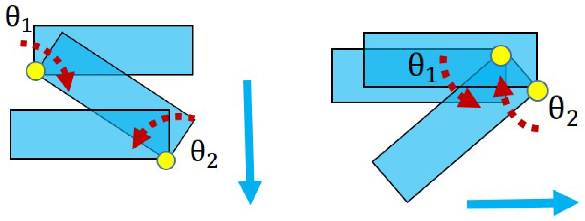
Figure 8.
Examples of moving an object to certain direction through pivoting gait. The red dashed arrows indicate rotating directions. indicates the amount of yaw rotation in the i-th sequence.
Figure 8.
Examples of moving an object to certain direction through pivoting gait. The red dashed arrows indicate rotating directions. indicates the amount of yaw rotation in the i-th sequence.

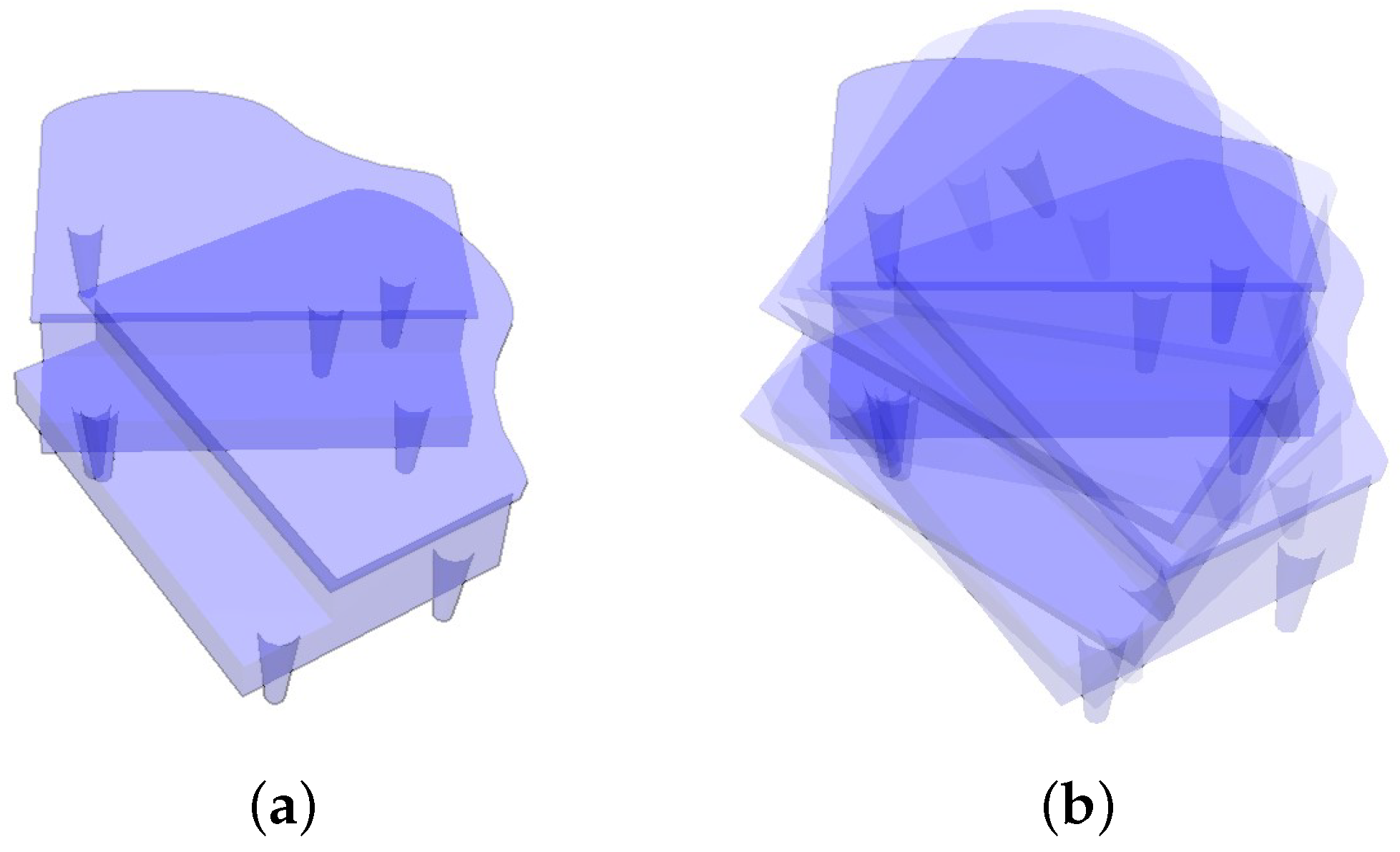
Figure 9.
Changes in the object’s rotational vertices (a) in the QS mode when four vertices are in contact with the table and (b) in the DS mode when two vertices are in contact with the table.
Figure 9.
Changes in the object’s rotational vertices (a) in the QS mode when four vertices are in contact with the table and (b) in the DS mode when two vertices are in contact with the table.

Figure 10.
The graphs generated at the task level. The object poses are first sampled and shown in the left graph, then the right graph is built by combining grasp configurations. (a) Graph of the sampled object poses. The red nodes indicate the object poses in SP, whereas the blue nodes indicate USP. The red and blue edges indicate pivoting and tumbling motion, respectively. (b) Grasps combined with the graph shown in (a). Each node includes information on both the object pose and grasp configuration. Yellow edges are added, which indicate the regrasping to change the grasp poses.

Figure 11.
(a) Portion of the graph in the rectangle depicted in Figure 10b. The nodes within the light blue circle share the same object pose and each node indicates the grasp configuration for the object pose. Nodes are connected by edges which correspond to primitive motions. (b) An object pose and a corresponding grasp pose. (c) Two grasp poses can be changed by the yellow edge connecting them. (d) The object pose in (d) can be changed to (b) or (c) by tumbling.

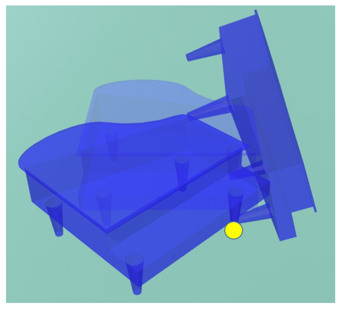
Figure 12.
Example of pivoting motion to move a piano. (a) Two poses of the piano. (b) Transformation of the object poses shown in (a) through pivoting motion. The object is tilted, rotated around one vertex, and then placed down.
Figure 12.
Example of pivoting motion to move a piano. (a) Two poses of the piano. (b) Transformation of the object poses shown in (a) through pivoting motion. The object is tilted, rotated around one vertex, and then placed down.

Figure 13.
A change of the object’s supporting base improves the ability of collision avoidance. The object motion following the gaits 1 cannot avoid a collision with the red obstacle. If the object is tumbled, the supporting base will be changed. Such a change allows the object to be moved without colliding the obstacle by performing the gaits 2. To pass a narrow passage, gaits 2 is more area-efficient than gaits 1.

Figure 14.
Tumbling motion by incorporating two manipulators.

Figure 15.
Manipulation of the piano by the robot for moving it forward by pivoting. The support vertices are marked as black dots. The initial configurations are shown in (a). The robot manipulates the object by pivoting in (b–d). When the joint configurations are close to the limits (d), regrasping is performed in (d–f). After regrasping, the robot moves the object to the goal pose, see (f–h).

Figure 16.
Experiment 1: The robot manipulates the object by pivoting in (a–d) and regrasping the object in (e–g). In (e), without regrasping, the robot cannot further move the object forward because the robot arms are close to the kinematic limit. However, after regrasping, the robot can move the object forward for two pivoting steps, see (h–j). The yellow dots indicate the object vertices that contact the table.

Figure 17.
Experiment 2: the robot changes the orientation of the object by pivoting and regrasping. The robot first rotates the object by pivoting in (a–c). Then the robot regrasps the object at its new contact surfaces, see (c–e) and pivots the object, see (e,f). In (f–h), the robot changes the grasp configurations and finally pivots the object to the goal pose, see (h–j).

Figure 18.
Experiment 3: An obstacle is placed in front of the object, see (a,b). The robot tumbles the object using the robot’s right EEF, whereas the left EEF moves to the desired position and waits for contacting the object (c,d). After the left EEF holds the object, the right EEF moves to the desired grasp pose (e,f). Note that the object is close to the boundary of the table and it is in a USP pose where the object will fall if there is no support from the EEF. After regrasping, the robot moves the object by pivoting it in the DS mode (g,h) and then places it in SP (i). The robot moves the object in the QS mode (j,k) and tumbles the object to change its support surface (l,m). Finally, the robot regrasps (m,n) and moves the object to the goal position (o,p). There is no collision between the object and obstacle during these motions.


Table 1.
Performance of superimposed segments.
| Process | Computational Costs | Results | Number |
|---|---|---|---|
| Superimposed segments | 0.354 s | Faces of the object | 262 |
| Sampling | 0.075 s | Contact points | 388 |
| Refine samples and plan contact pairs | 2.115 s | Contact pairs | 107 |
Table 2.
Performances of the graph MPC and the proposed planner.
| Methods for Generating Motions | Ability to Regrasp | Error (x-axis) |
|---|---|---|
| The graph MPC | No | −12.5 cm |
| The proposed planner | Yes | 0 |
Publisher’s Note: MDPI stays neutral with regard to jurisdictional claims in published maps and institutional affiliations. |
© 2021 by the authors. Licensee MDPI, Basel, Switzerland. This article is an open access article distributed under the terms and conditions of the Creative Commons Attribution (CC BY) license (https://creativecommons.org/licenses/by/4.0/).
Share and Cite
MDPI and ACS Style
Zhang, A.; Koyama, K.; Wan, W.; Harada, K. Manipulation Planning for Large Objects through Pivoting, Tumbling, and Regrasping. Appl. Sci. 2021, 11, 9103. https://0-doi-org.brum.beds.ac.uk/10.3390/app11199103
AMA Style
Zhang A, Koyama K, Wan W, Harada K. Manipulation Planning for Large Objects through Pivoting, Tumbling, and Regrasping. Applied Sciences. 2021; 11(19):9103. https://0-doi-org.brum.beds.ac.uk/10.3390/app11199103
Chicago/Turabian StyleZhang, Ang, Keisuke Koyama, Weiwei Wan, and Kensuke Harada. 2021. "Manipulation Planning for Large Objects through Pivoting, Tumbling, and Regrasping" Applied Sciences 11, no. 19: 9103. https://0-doi-org.brum.beds.ac.uk/10.3390/app11199103
Note that from the first issue of 2016, this journal uses article numbers instead of page numbers. See further details here.