Experimental Research on Foil Vibrations in a Gas Foil Bearing Carried Out Using an Ultra-High-Speed Camera


Institute of Fluid Flow Machinery, Polish Academy of Sciences, 80-231 Gdańsk, Poland
*
Author to whom correspondence should be addressed.
Appl. Sci. 2021, 11(2), 878; https://0-doi-org.brum.beds.ac.uk/10.3390/app11020878
Submission received: 18 November 2020
/
Revised: 6 January 2021
/
Accepted: 14 January 2021
/
Published: 19 January 2021
(This article belongs to the Section Mechanical Engineering)
Abstract
:The foil bearing consists of parts made of very thin, properly shaped foils. Usually, it is very difficult or even impossible to measure the vibrations of these elements during the bearing operation using traditional sensors. Therefore, the authors of this article have proposed an entirely new approach to this issue. This article discusses the analysis of vibrations of the structural supporting layer of a gas foil bearing at high rotational speeds. Instead of using a traditional method to measure the bearing journal movement, the measurement was performed using an ultra-high-speed digital camera. This type of measurement was used for the first time to analyse foil bearing displacement. It turned out that doing so can give a far more vibrant picture of what is happening in gas foil bearings during their operation. The article includes an analysis of foil vibrations. This phenomenon has already been analysed numerically, and this is the first time it has been analysed experimentally. The registered motion of the foils can be compared with the results obtained from numerical models, thus allowing their further development. One such comparison is shown in this article.
1. Introduction
An evaluation of vibrations in fluid-flow machines is usually done using accelerometers, eddy current sensors, laser sensors or other types of sensor. High-speed cameras are rarely used for this purpose. Our article aims at filling this gap. We also want to show that a high-speed camera can serve as a useful tool to analyse the operation of a foil bearing. In addition to tracking the motion of the journal or sleeve of the bearing (which can be easily done using traditional sensors), it is possible to analyse displacements of the bump foil (which is impossible to do using the vast majority of the sensor types mentioned above). In the first part of the introduction, we gave general information about foil bearings. In the second part, we gave several examples of the use of high-speed cameras not only for conducting research on bearings. The analyses were mainly focused on two aspects: cavitation analysis and dynamic properties. Based on the literature review, we are of the view that the use of high-speed cameras is becoming more common in many fields of science.
1.1. Foil Bearings
A foil bearing is the type of bearing that is relatively new but is becoming increasingly common around the world. The first papers about foil bearings were published in the 1950s. Since then, the design and materials of foil bearings have changed significantly, but the principle of their operation has remained unchanged. A key element of a bump-type foil bearing is a set of compliant foils, usually made of thin metal sheets. So far, many experimental, analytical and numerical techniques for predicting the performance of foil bearings have been developed. Such parameters as load capacity, power loss, the temperature of the bearing parts as well as static and dynamic stiffness or damping can be thoroughly analysed experimentally. Different approaches are used to research the compliant bearing structure. Most of them are a variety of numerical methods. Modelling of the dynamic behaviour of the foil bearing structure, due to its mechanical complexity, remains a challenge for scientists and engineers from all over the world. Foil bearings operate with a relatively thin hydrodynamic lubricating film, which changes within a narrow range. Therefore, the overall stiffness and damping of a foil bearing depend mainly on the compliant supporting structure, rather than on a very stiff gas film.
The first dynamic models of the foil bearing structure were most often based on static models [1]. The model, which was developed by Ku and Heshmat, considered the elastic deformation of the bumps, the friction between the corrugated foil, the top foil and the sleeve, the interaction between the bumps as well as the curvature of the sleeve. The dynamic stiffness and damping of the entire bearing were obtained using a single-DOF (degree of freedom) model.
Rubio and San Andres [2] provided test results for a bump-type foil bearing structure as well as stiffness and damping (Coulomb- and viscous-type) coefficients. The dynamic tests were conducted on a stiff non-rotating shaft. In 2010, Conlon et al. [3] presented an experimental evaluation of the steady-state (load capacity) dynamic performance of first- and second-generation foil bearings of a relatively large size (with a nominal diameter of 70 mm) under various controlled operating conditions. These tests aimed at collecting high-fidelity data needed to validate the theoretical model of a foil bearing.
Bagiński et al. [4] presented the results of experimental research carried out on foil bearings operating under elevated temperatures. The dynamic properties of the bearings were also investigated when a cooling system was turned on. This article presents various methods for cooling foil bearings and discusses the impact of these methods on dynamic parameters of the rotating system equipped with such bearings. The authors of the article measured the temperature of the top foil using thermocouples. They showed that their measurement method did not exert any significant impact on the functioning of the rotor-bearings system.
Żywica et al. [5] wrote an article in which they discussed experimental research and simulation tests of foil bearing prototypes. All these tests were carried out on a special test stand under different operating conditions (including a broad speed range). This study shows that adverse operating conditions caused the bearing damage after its short operation, accompanied by a significant increase in temperature. The main factors that affected the durability of foil bearings were the material used for coatings of the mating surfaces, bearing geometry, way of assembling the bearing, speed, and load. To better understand the physical phenomena that occur in foil bearings, a numerical model has been developed which enabled performing thermal analyses. The results showed that the design process of a new foil bearing could be a challenging task. It needs many aspects to be considered, including the elements directly related to the operation of the bearing alone, as well as those related to the operation of the rotor and operating characteristics of this machine.
The influence of selected geometric parameters on the dynamic performance of bump-type foil bearings was analysed by Kulkarni and Jana [6]. They dealt with the effect of the stiffness and clearance on the load-carrying capacity of these bearings. Experimental results indicated that the clearance had the most significant influence on the lift-off speed and load-carrying capacity of the bearings. The effect of structural friction between some parts of foil bearings was also analysed by Xu et al. [7]. They did experimental tests for two sets of the bearings with different roughness of the sleeve surface, which showed that structural Coulomb friction made the bump foil stiffer and limited its displacement in the foil bearing.
Bonello and Bin Hassan [8] presented an experimental and theoretical analysis of a foil-air bearing rotor system. Authors wrote that although there is considerable research on the experimental tests of foil-air bearing rotor systems, only its small part has been correlated with simulations from a fully non-linear model that combines the rotor, air film and foil domains, due to modelling complexity and computational time. Gu et al. [9] presented stability and vibration characteristics of a rotor-gas foil bearings system with high-static-low-dynamic-stiffness supports. The use of proper flexible supports can improve the stability performance of a rotor-bearings system. The research aimed at studying synthetically the effects of support stiffness and damping on the dynamic characteristics of the rotor-gas foil bearing system, i.e., stability, unbalance and shock vibration characteristics. Larsen and Santos [10] wrote the article in which they show the theory and experiments about the non-linear steady-state response of rigid rotors with air foil bearings. The study gives theoretical and experimental contributions by implementing and validating a new method to simulate the non-linear steady-state response of a rotor with three pads.
1.2. Overview of High-Speed Camera Applications
Analyses with high-speed cameras cover a wide range of applications. In this article the first time the high-speed camera is used to analyse foil bearings. Below are examples of other similar applications. Staudt et al. [11] presented the results of their observations of the deep penetration laser welding process using the hyperspectral imaging (HSI) technique. The authors developed an appropriate high-speed camera-based HSI system. Designing and optimising production processes enables us to derive spectra of the deep penetration welding process with high time resolution. Research using high-speed cameras is often conducted during flow analyses, which was shown by Miles in article [12]. Since 2000 there has been rapid development of diagnostics of high-speed airflows. The foundations for this development were laid over the past few decades. With the development of new short pulse and pulse burst laser technologies, higher laser powers and higher pulse energies, new high-speed cameras, better laser control, improved detection, and laser delivery methodologies, as well as many beneficial new capabilities, have been developed. Wu et al. [13] showed that it is possible to use a system consisting of two high-speed cameras in order to analyse the dynamic performance of a robot. Industrial robots are widely used within the industry. However, there is a need for higher accuracy and stable performance in these applications. When a robot is performing a machining task in particular, the dynamic performance of the machining process influences the quality of the workpiece. In this article, a measuring system with a high-speed camera is used to analyse the robot’s movement in order to improve the process. Linear paths with different accelerations were programmed. The position distributions in 3D space are presented, and the linearity of the tracks is discussed. Liu et al. [14] presented a paper describing a videogrammetric technique used to conduct shaking table tests of multi-layer structure models using a pair of cameras with CMOS (Complementary Metal Oxide Semiconductor) sensors.
Znamenskaya et al. [15] presented optical tests of the dynamic performance of a high-pressure water and sewage system. The article discusses the results of visual tests of streams of fast-flowing fluids ejected from a nozzle at a pressure of 400 MPa. The research aimed at investigating biphasic flows under extremely harsh operating conditions and also at analysing the possibility of optimising the design of the device. Zeleňák et al. [16] presented a paper in which they deal with visualisation and velocity analysis of a self-excited water jet generated by a developed prototypical hydrodynamic nozzle. A high-speed camera in combination with four high-power pulsing light-emitting diodes (LEDs) and the particle image velocimetry method was tested.
The application areas of vision methods are not limited only to technical sciences. They are also used in a variety of different areas of life. Hassan et al. [17] presented a feasibility study of the heart rate measurement in which they used a digital camera for health monitoring. Sánchez-Pay et al. [18] presented an article describing the measurement error identification associated with the mean movement velocity, in which methods based on a high-speed camera and video analysis were used during resistance experiments.
A high-speed camera works particularly well in research on cavitation occurring in hydrodynamic bearings. The impact of viscosity on the cavitation characteristics of a high-speed sleeve bearing was tested theoretically and experimentally by Wang and Lu and described in their article [19]. The cavitation characteristics, cavitation shape, and cavitation location of a spiral oil wedge hydrodynamic bearing were studied experimentally using the transparent bearing and a high-speed camera. The generalised Reynolds equation was derived, taking into account the cavitation mechanism based on the modified Elrod method, and the cavitation of sleeve bearings with different viscosity parameters was analysed and compared. There was a great deal of similarity between the experimental results (measured using a high-speed camera) and the theoretical results. Jacobson and Hamrock [20] used a high-speed camera to analyse transverse bearings operating under different dynamic loads. The study aimed at determining when and where cavitation occurred in the bearings. It affected both the energy loss and operating stability of the bearing. A high-speed camera was used to test cavitation in dynamically loaded radial bearings. The ratio of the length of the bearing to its diameter, the rotational speed, the material with which the shaft was coated as well as the static and dynamic eccentricity of the bearing were changed. The results obtained indicate not only the occurrence of gas cavitation but also the development of steam cavitation (which was not expected).
Tong et al. [21] presented research on three-camera videogrammetry for three-dimensional measurement of laminated rubber bearings based on a shaking table. Laminated rubber bearings are widely used to mitigate seismic damage to large structures and equipment. In this work, a three-dimensional measurement of the displacement of a laminated rubber bearing based on a large-sized shaking table was performed. Authors used three high-speed CMOS cameras, one synchronous controller, and one pair of 1000 watt light sources, which were used to simultaneously acquire three-camera sequences of a laminated rubber bearing image at 300 frames per second (fps). This article proposes a fast image blocking technique to detect and track objects in three-dimensional image sequences by integrating methods for morphological edge detection, attribute-based ellipse extraction, and least-squares based matching adjustment.
Durand-Texte et al. [22] presented Single-camera single-axis vision method applied to measure vibrations. The authors wrote that 3D vision methods used with two high-speed cameras turned out to be a valid solution to measure 3D displacements, particularly with the stereo digital image correlation (SDIC) tool. The conventional pseudo-stereo system with a single high-speed camera and a four-mirror adapter, generating two virtual cameras, may also be used, even if it is rather difficult to operate and is limited to small objects.
Wang et al. [23] presented tests of speed estimation using a visual method. Diagnosis of engine bearing faults at variable speed can sometimes be a problem. This paper proposes a new, computer vision-based order tracking method to address this problem. First, video footage recorded by a high-speed camera is analysed using an accelerated, robust algorithm used to extract and match functions to obtain the instantaneous motor speed (IRS). Then, an audio signal picked up by a microphone was polytonally sampled to follow the IRS curve, so that the signal could be represented in the angular domain instead of the frequency domain. The envelope sequence spectrum was then calculated to determine the damage pattern. The effectiveness and strength of the proposed method were verified using two brushless test stands for D.C. motors, where two damaged bearings and a healthy bearing were tested separately. This test used a new, non-invasive approach to measurement, which made it possible to avoid the installation of a tachometer and overcome the drawbacks of methods of tracking the order of motor bearing damage at variable speed.
Köhl et al. [24] presented experimental and numerical research carried out on a car turbocharger with a transparent bearing section. The dynamic performance of the car turbocharger supported by bearings with a full floating ring was tested experimentally and numerically. The movement orbit of the rotor was mounted on the compressor side and, after modifying the turbocharger’s housing, the speed of the floating ring were tested. Using a high-speed camera and subsequent image analysis, the MATLAB software was used to detect communication holes along the circumference of the floating ring and then the speed was calculated.
The various tests with high-speed cameras which have been presented so far mainly concern analyses of cavitation and the dynamic performance of individual bearing components. There are no articles describing research in which a high-speed camera was used to analyse entire foil bearings. With the rapid development of these bearings, new numerical studies are being developed, which attempt to describe the system in detail. The standard tools that are used for monitoring the technical condition of fluid-flow machines are proximity sensors, e.g., eddy current sensors and accelerometers placed on bearing housings. None of these techniques enables performing analyses of supporting foils, which are a crucial element for the proper functioning of foil bearings. This article fills this gap in the current state of knowledge, providing data that can be used as reference values in numerical analyses.
2. Material and Methods
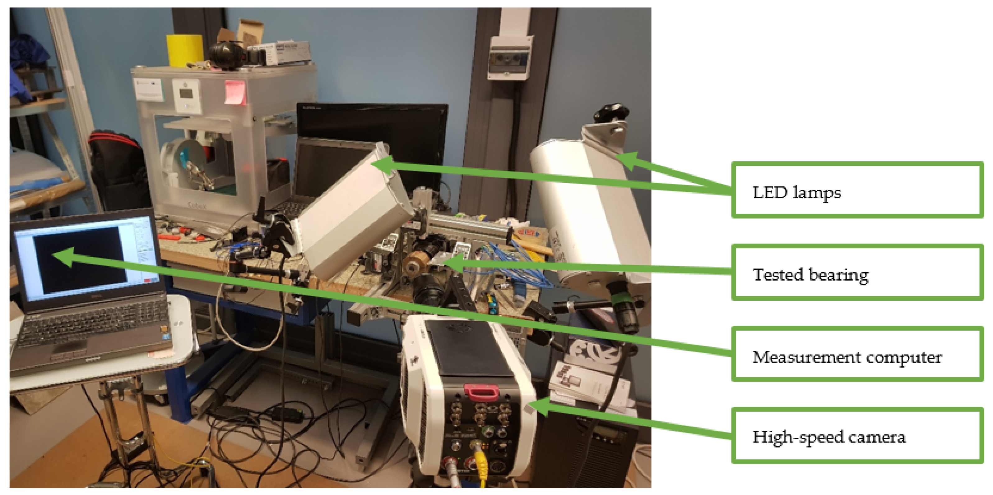
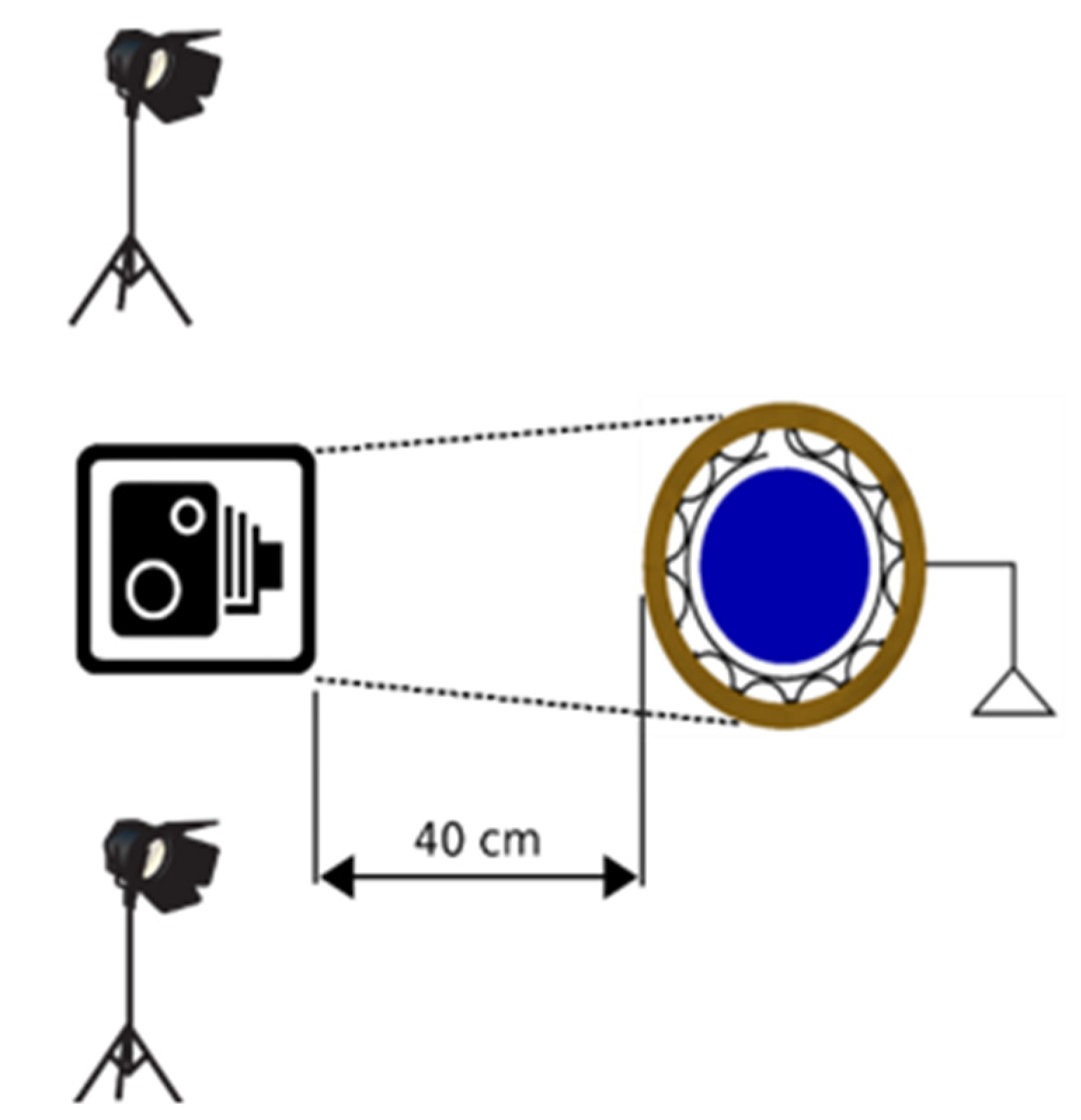
We researched the foil bearing’s structure on a specially prepared test rig, located in the Vibrodiagnostics Laboratory of the Institute of Fluid-Flow Machinery of the Polish Academy of Sciences (IMP PAN). The tested bearing was mounted on a shaft with a diameter of 34 mm. The shaft was put in rotational motion using an electrospindle whose maximal speed is 24,000 rpm. Figure 1 shows the laboratory test rig with an ultra-high-speed camera. The camera was controlled by the measuring computer that is also shown in this figure. We used two 60 W light-emitting diode (LED) lamps (PRO 2X Oslon 60 model, manufactured by Easy LED) for better illumination of the tested bearing. Each lamp can deliver light output up to 6000 lumens. A diagram of this test stand is presented in Figure 2. The camera was situated almost in front of the rotating shaft and the two light sources were positioned to provide light to the bearing on both sides.
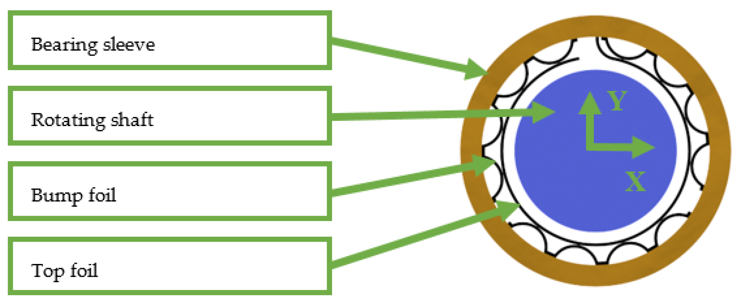
A diagram that shows how the bearing is mounted on the shaft is presented in Figure 3. The shaft is a part of the electrospindle that is attached to the aluminium frame. The shaft’s journal was inserted into the bearing sleeve before research. When the rotational speed of the shaft was high enough, a gaseous lubricating film formed itself between the top foil and the bearing journal. During the research, the bearing sleeve rotation was blocked. The sleeve was able to move in the radial direction. The bearing is lifted after the lubrication film appears. The foil bearing consists of two foils. The bump foil is situated between the rigid sleeve and the top foil. The foils were manufactured from Inconel 618 and the top foil was coated with Teflon. The length of the bearing is 40 mm.
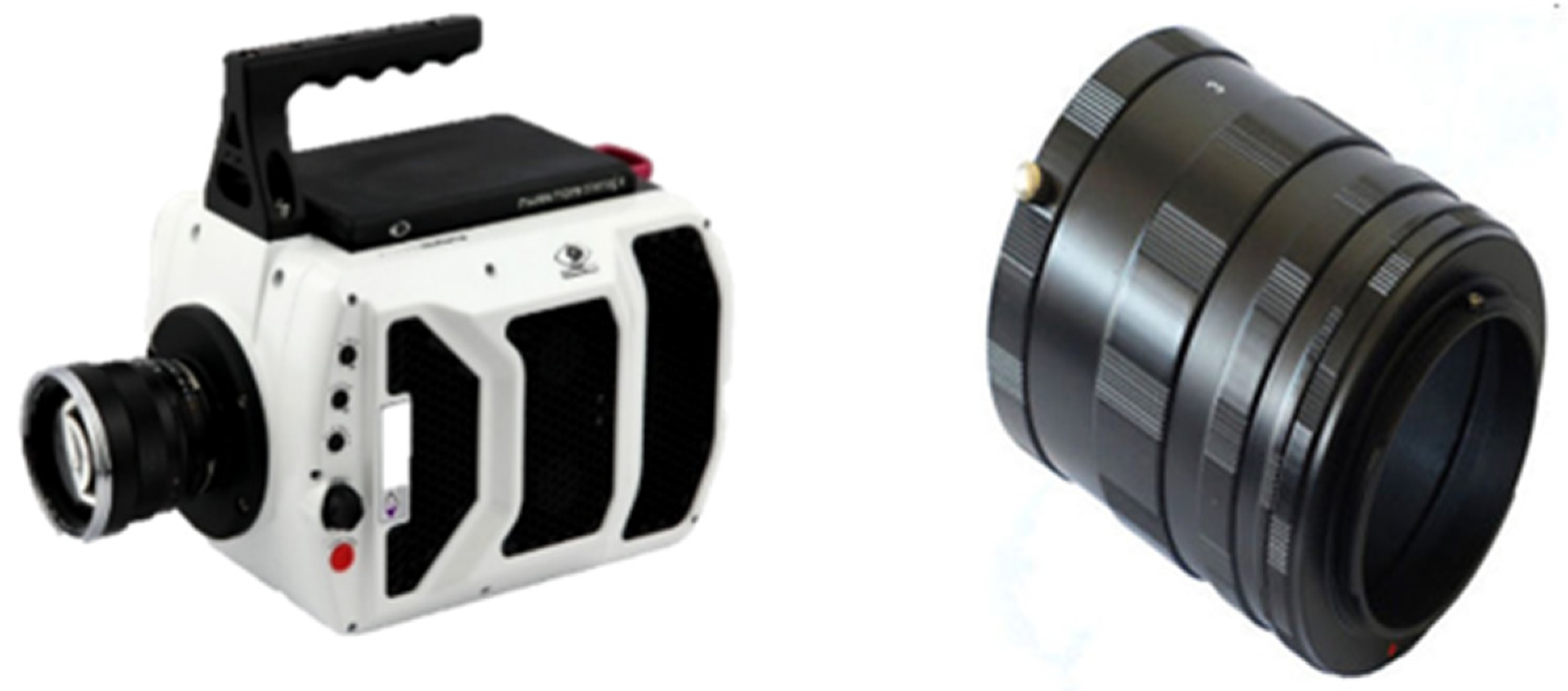
Vision Research’s v2511 ultra-high-speed camera (shown on the left-hand side of Figure 4) was used to record the tests of the bearing carried out under different operating conditions. The camera is equipped with a CMOS sensor that allows capturing high-resolution images at very high speeds (offering a full megapixel resolution of 1280 × 800). Moreover, the CMOS sensor has pixels with a diameter of 28 µm. Acquiring around 25 gigapixels-per-second of data enables frame rates up to 1,000,000 fps at 128 × 32 resolution. When recording with the maximum resolution, the maximum frame rate is 25,600 frames per second. We connected the camera with the measuring computer using the Ethernet communication interface. We tested run-ups, stable operation, and impulse excitation—an analysis of the recording in slow-motion followed. We also used the TEMA Motion software, developed by Image Systems, which is dedicated to performing advanced motion analysis. For recording purposes, we used a Zeiss 100 mm f/2 macro lens whose main features are the following: the maximum reproduction ratio is 1:2 and the minimum focusing distance is 0.4 m. Two sets of extension tubes (shown on the right-hand side of Figure 4) were placed between the lens and the camera. The extension tubes do not include any magnifying lenses but can be combined if there is a need to increase the reproduction ratio. Those adapter rings enable increasing the distance between the focal plane of the lens and the CMOS sensor, thus increasing the reproduction ratio. In practice, the farther we move the lens away from the camera (using the extension tubes), the better magnification of the test object we obtain. One set of extension tubes includes rings with three widths (7 mm, 14 mm, and 28 mm) and two bayonet fixings between the camera and the lens. After assembling two such sets, the distance between the lens and the camera was 128 mm.
Conducting measurements using the aforementioned high-speed camera has some limitations. The measured vibration frequency is limited by the frame rate of the high-speed camera. During the measurement, we needed to avoid aliasing. The next issue we needed to take into consideration is that when the frame rate was increased to the highest possible value, there was a need to reduce the resolution. In practice, a high-speed camera can be used to record very quickly changing phenomena such as cracking of the material or the propagation of a thunderstorm. We can give a practical example of the calculation of the maximum rotational speed by giving one example. Let us assume that we need 20 measuring points for one rotation of a shaft. This means that to measure the shaft rotating at a speed of 3000 rpm (50 Hz), we need to record the movement at a frame rate of at least 1000 fps (50 × 20 = 1000). The maximum frame rate of the high-speed camera is 12,800 fps at the highest possible resolution. This means that we can record the shaft rotating at a speed as high as 38,400 rpm. In practice, the resolution of the high-speed camera can be slightly reduced to easily track the phenomenon, even at a rotational speed of 100,000 rpm or considerably higher (or to measure a lower number of points per rotation of the shaft). The maximum/minimum vibration amplitude is defined by the resolution of the camera sensor and the lens used. Because we have access to a variety of lenses (including micro and macro lenses, which offer a wide field of images from telephoto range to wide-angle shots), we can easily measure vibrations of different amplitudes.
3. Results and Discussion
3.1. Stable Operation
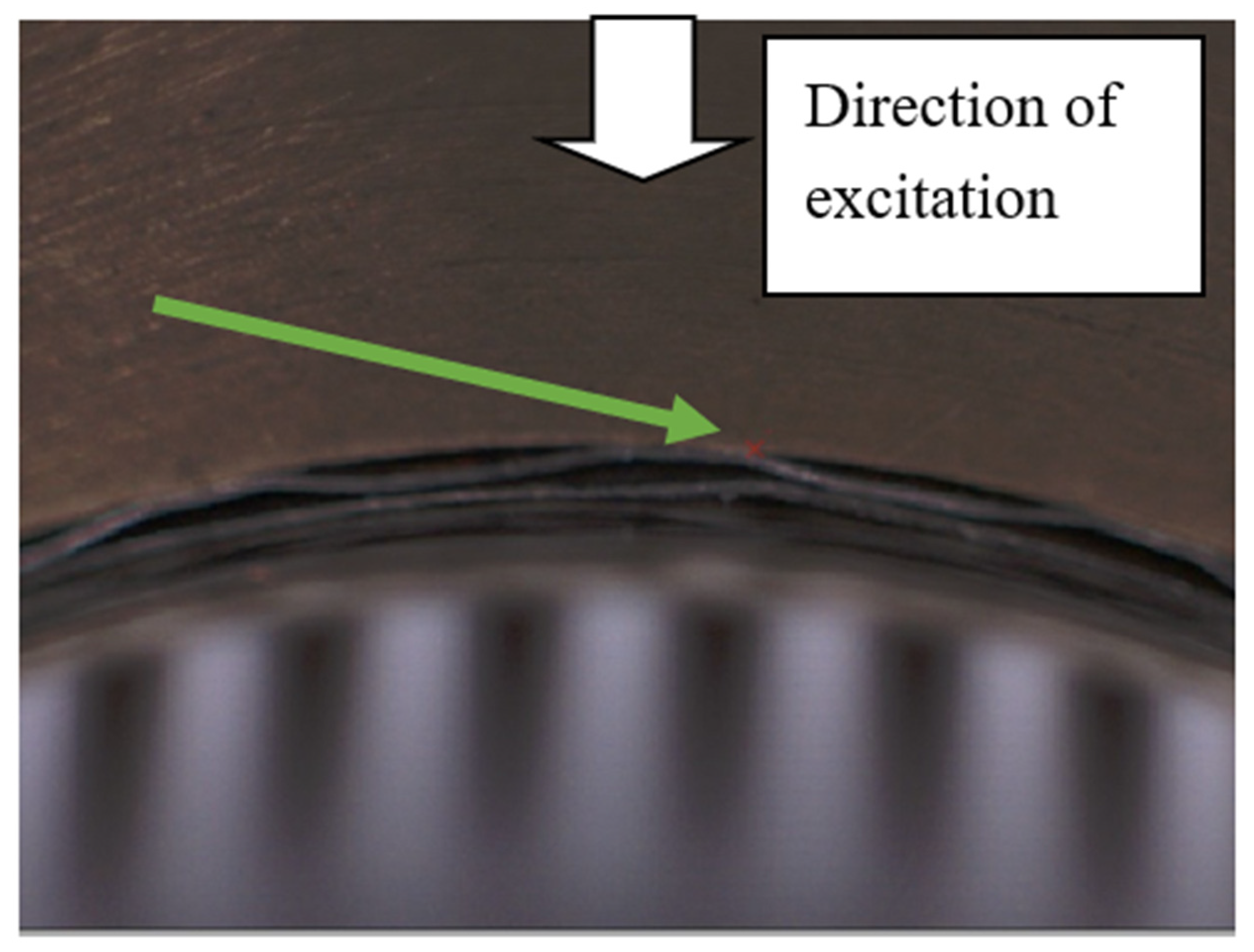
Figure 5 shows the point for which displacements were analysed. During the operation of the rotor, the foils of the foil bearing moved cyclically. The bumps of the bump foil usually supported the top foil firmly and there was no free space between these foils. Sometimes, when the shape of the bump foil differed significantly from the ideal profile (which could be due, for example, to manufacturing accuracy) or there was a large clearance in the bearing for some reason, some changes in the gap height between the foils were observed. The bearing components were cyclically pressed against each other by the rotating and moving shaft, resulting in changes in the geometry of the gaps.
The displacement in the horizontal direction of the point located on top of the bump of the bump foil (Figure 5) is shown in Figure 6. The data come from the time course registered during operation at a rotational speed of 24,000 rpm. With each rotation, it can be seen that the bump is pressed by the top foil (during the shorter and larger displacements). In this case, the irregular operation associated with inaccurate manufacturing affects the dynamic behaviour of the foil. All of this also translates into the different nature of the operation of the rotor supported by foil bearings. It should be emphasised here that a properly functioning bearing was analysed, where almost all bumps supported the structure steadily. The fragment analysed constitutes only a small portion of the bearing. The example presented can illustrate why it is so difficult to analyse foil bearings numerically. In such analyses, most researchers assume that the bearings are perfectly made.
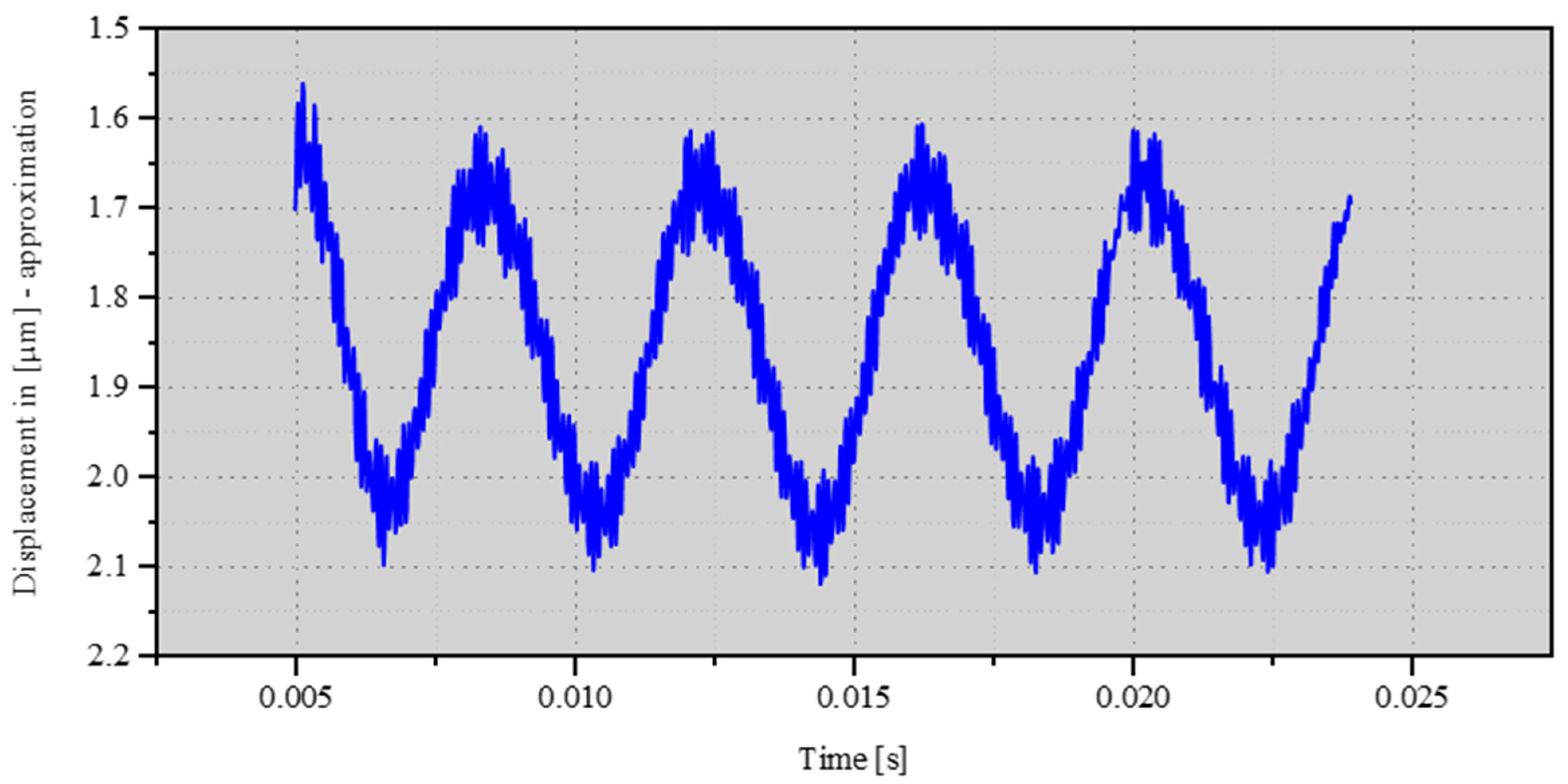
Figure 7 shows the vibration of the top foil located between the bumps. The area is similar to that shown in Figure 5 but the measurement was carried out under different operating conditions. This is the stable operation of the properly manufactured foil bearing. The frequency of the vibration is equal to the rotational frequency. The peak-to-peak amplitude of the vibration is equal to 0.5 µm. This kind of movement can be observed quite frequently in a foil bearing.
3.2. Small Impulse Excitation Force
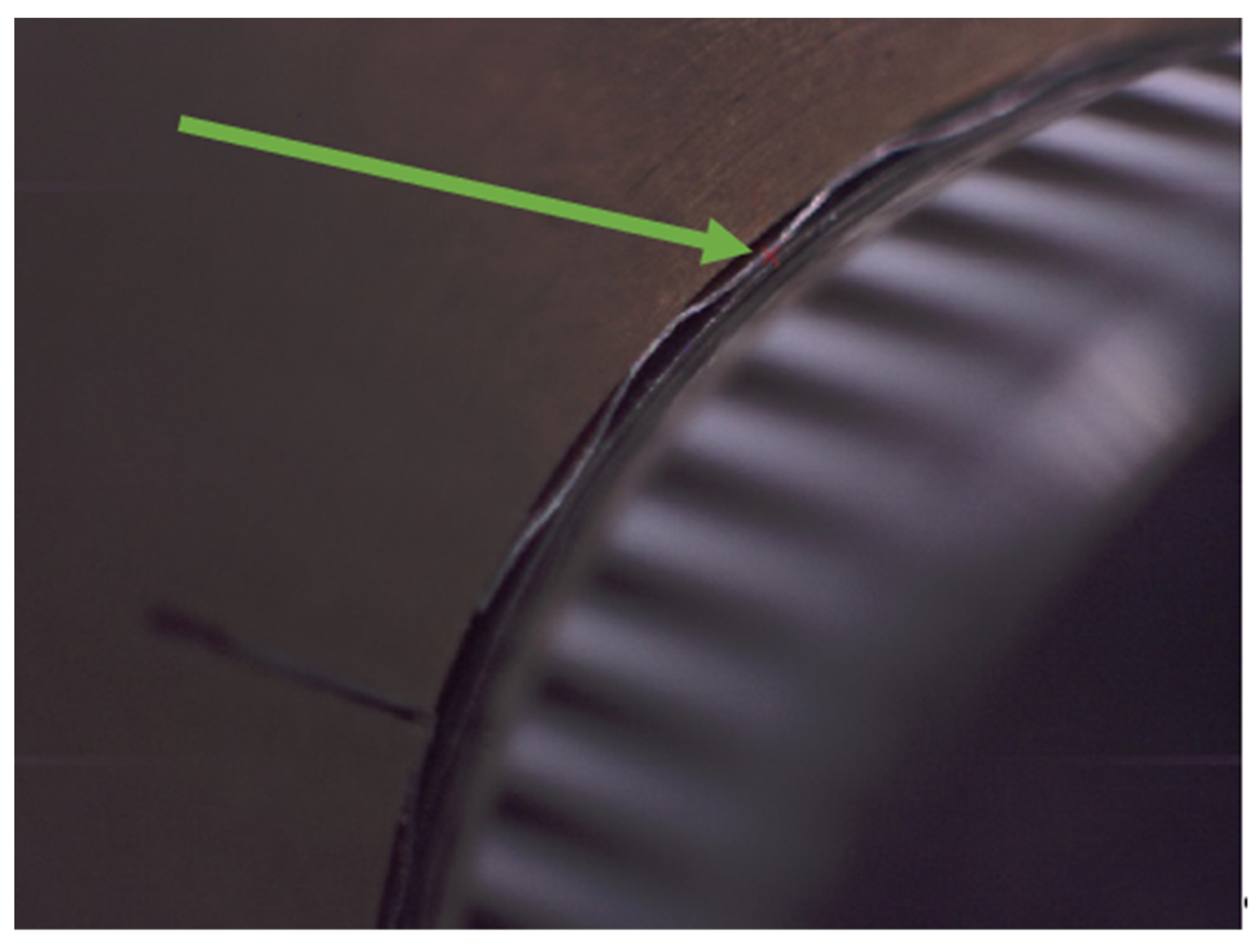
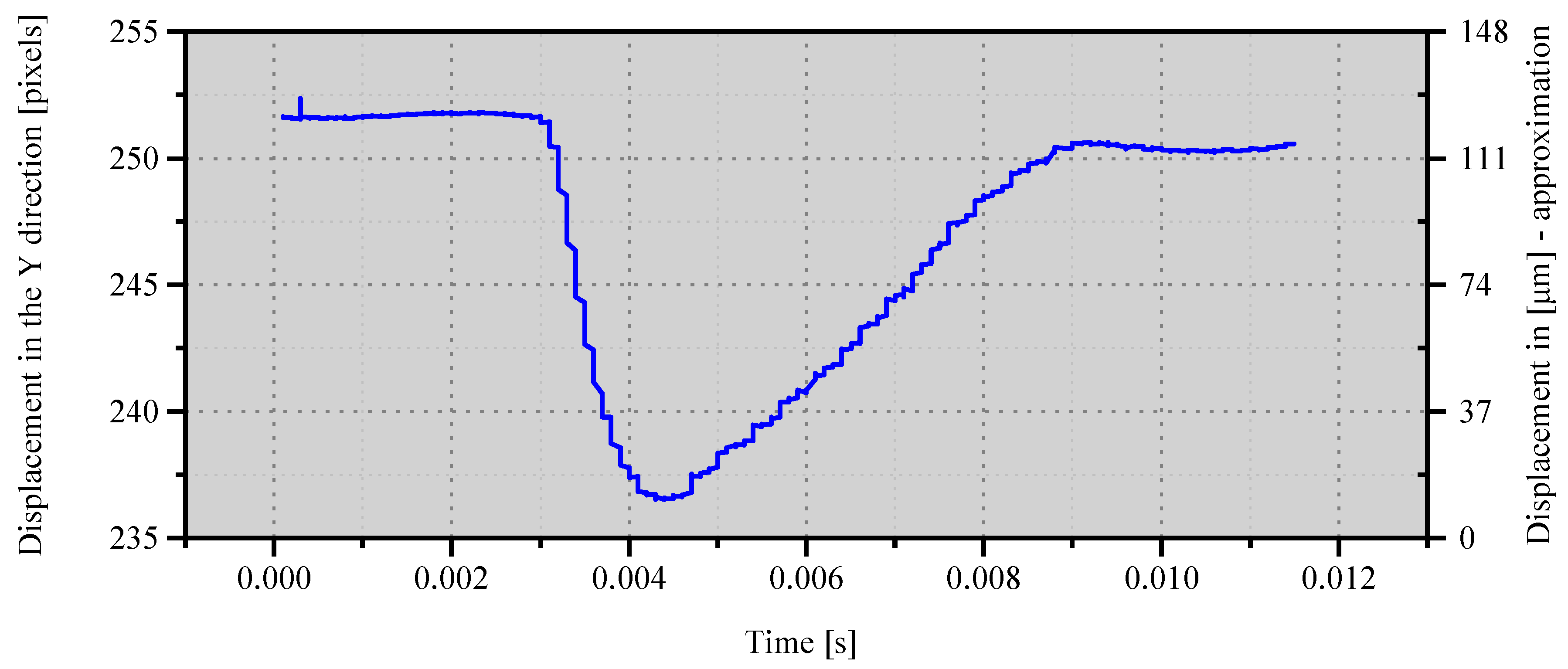
In the research presented, the bearing placed on the rotating rotor shaft was hit twice. The value of the excitation force has not been accurately measured; but, in the first case, it was approximately 100 N. The displacement of the point, located (on the surface of the sleeve) very close to the foils supporting the bearing, was measured.
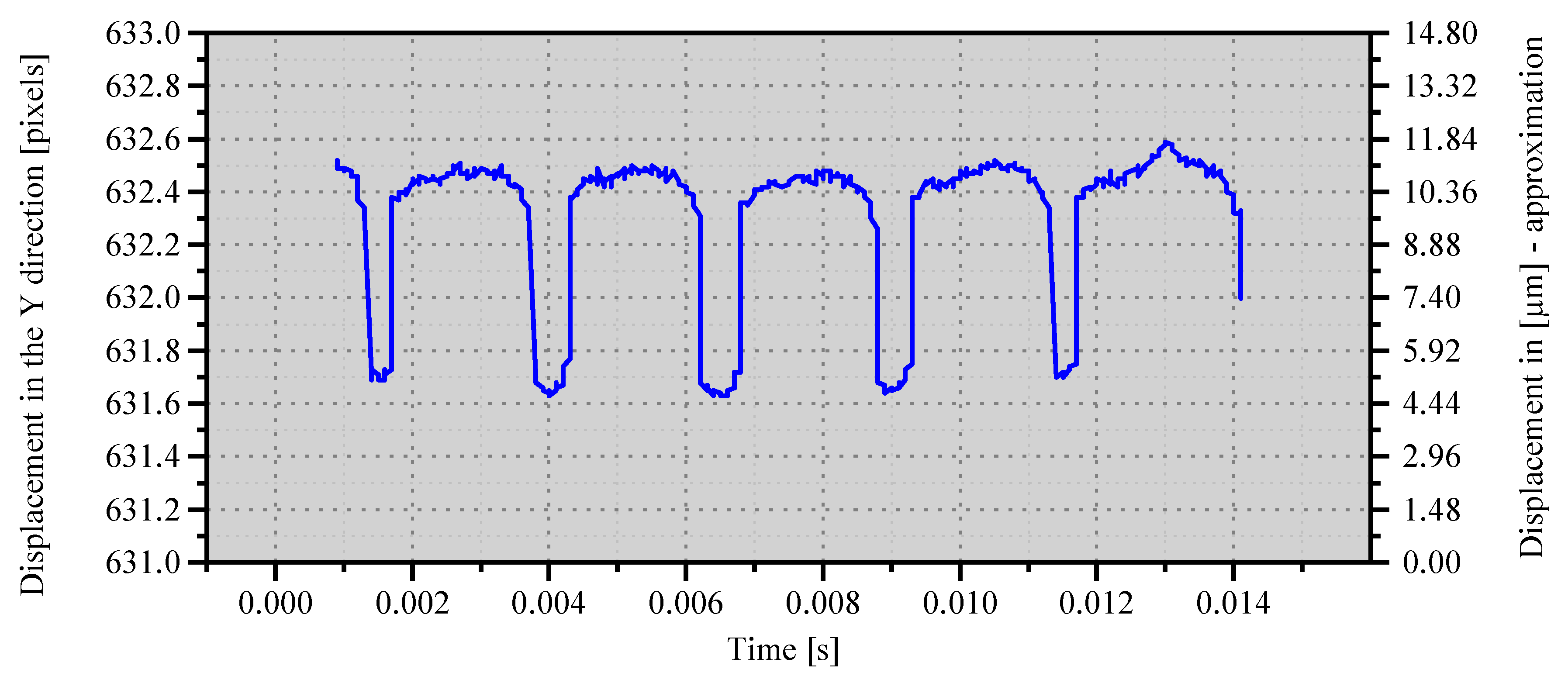
The displacement in the vertical direction of the point illustrated in Figure 8 is shown in Figure 9. The figure shows that the displacement lasted about 0.05 s. The unit of the axis of ordinates is pixels because the points in the image are tracked with such accuracy. To estimate the correlation between pixels from the high-speed camera and the displacement expressed in micrometres, we used the recordings of known geometry of the bearing. We did this calculation using the same positions of the camera and bearing as those used in the following measurements. We know how large the maximum displacement of the bearing sleeve was when it was pushed to one side with a great force (because this is how we assembled the bearing). We recorded this movement using a high-speed camera. The next calculation was easy, we divided known recorded displacement (analysed by the TEMA Motion software) by a known distance. We assumed that the displacement was linear, which means that each pixel recorded by the high-speed camera represents the same distance of the movement. According to rough calculations, one pixel corresponds to a displacement of 7.4 µm. The displacement recorded by a high-speed camera was 15 pixels (111 µm). The figure also shows that after being subjected to an excitation force, the bearing operated in a different position than it had before—the entire sleeve moved one pixel down, that is to say about 7.4 µm.
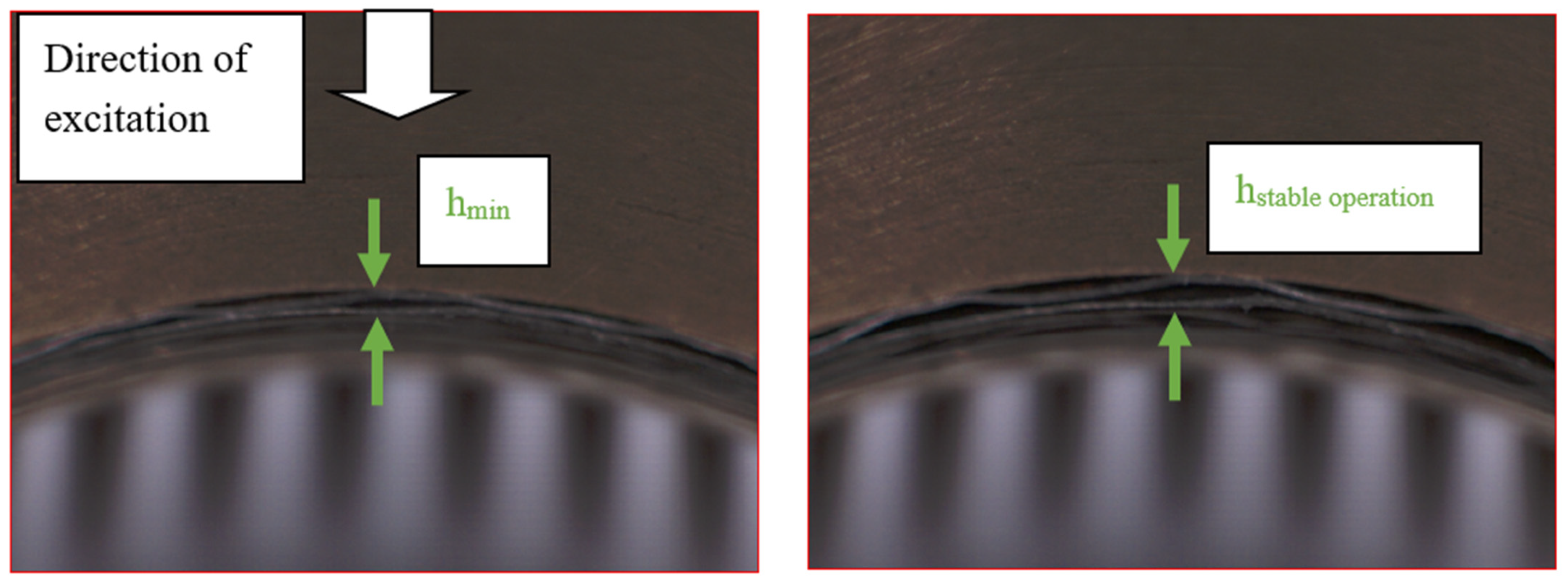
3.3. Large Impulse Excitation Force
Figure 10 shows a portion of the tested bearing at two different points in time after an excitation force was applied using a hammer. The value of the excitation force was not measured but its value was about 200 N. This is the value of the force that can destroy the bearing. On the left-hand side, we can see the maximum deflection of the foils due to the impact, and it was the moment when the distance between the bearing sleeve and the rotating rotor was the shortest. The most significant deflection was observed for the bump foil, whose height was approximately 400 µm before the excitation and decreased by around 50% after it. The camera recorded displacement of the bearing (which was about 200 µm) by registering movement of 27 pixels; by dividing these values we were able to estimate the value of bearing displacement. One pixel on the photograph corresponds to a movement of the bearing of 7.4 µm. On the right-hand side of Figure 10, we presented a photo of the bearing, which was taken soon after the time when its operation became stable again. The bearing was overloaded only for a short period, and the journal took its previous position shortly after that.
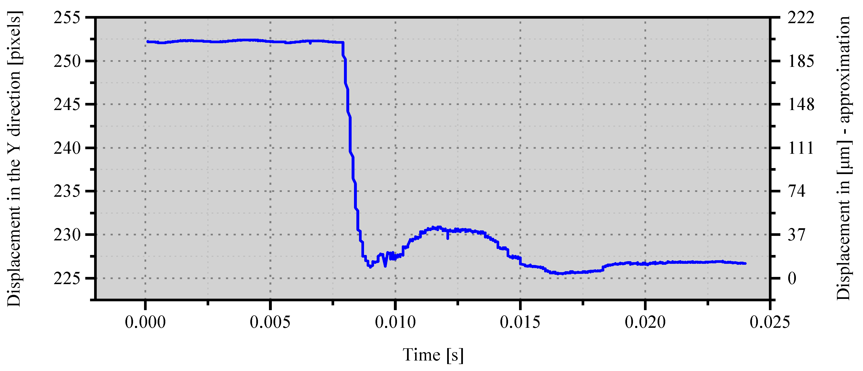
In Figure 11, we showed the displacement of the bearing sleeve versus time, registered after impulse excitation was applied during operation at a rotational speed of 24,000 rpm (i.e., the maximum speed). This time, the magnitude of the excitation force was higher than that of the force used in the test shown in Figure 10. It turns out that when the magnitude of the excitation force was too large, the plastic deformation of the bump foil took place. Even though the bearing was still able to operate, its operational characteristics changed. In a foil bearing, the pre-clamp is an essential parameter. If the pre-clamp is not firm enough, the entire space between the top foil and the bearing sleeve will not be adequately filled by the bump foil. In such a case, during operation at the nominal speed, the rotor (due to the unbalance) keeps pressing against the top foil that can deflect in places in which the bump foil is not tightened firmly. The vibration amplitude of the rotor is then significantly increased. We observed such behaviour only in several cases when we used the bump foil, whose bumps were not high enough.
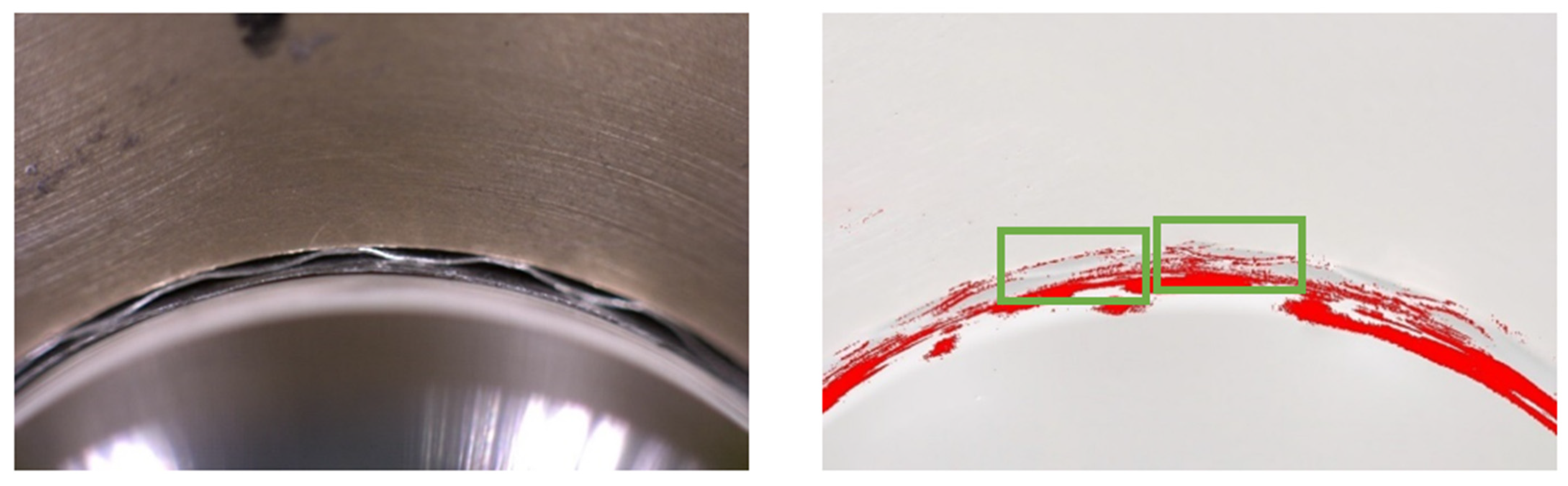
A screenshot from a recording made using a high-speed camera is shown in Figure 12 (on the left side). This is a recording of the top part of the bearing. At the bottom of the screenshot, there is the rotating shaft whose speed was 24,000 rpm. On the right image shown in Figure 12 the differences between the two extreme shaft positions are marked with rectangles. The pixels that differ in these positions are marked in red. Two green boxes were used to label two bumps of the bump foil. The whole bump located inside the right rectangle is marked in red. On the left-hand side, the bump situated inside the frame is almost white (i.e., the number of red pixels is small). It means that on the right-hand side, the entire segment bends, and thus it takes part in the bearing operation. The differences between the sections are due to the non-homogeneous manufacture or assembly of the foils. These differences affect the dynamic properties of whole foil bearings.
During operation at a constant speed, we noticed vibrations of the portion of the top foil, which was situated between the bump foil’s bumps (it is visible in Figure 12 (right)). The red dots were created based on the differences between the two frames recorded at different times. The more red dots, the more differences between the two frames and the difference in time is half a rotation of the shaft. The vibration frequency was the same as the rotational frequency of the shaft. We observed one cycle of the sinusoidal waveform per one complete revolution of the shaft. Such vibrations were not present in each configuration of the tested bearing. Łagodziński and Miazga [25] have already investigated this phenomenon using numerical simulations. In addition to numerical research, they carried out an experimental study that showed how to make the foils assembly more rigid (using an additional intermediate foil), thus improving the dynamic parameters of the bearings. Another way of improving the dynamic properties of a foil bearing is to make its top foil more rigid. The phenomenon we observed is not noticeable with the naked eye. Only after the preparation of recordings using an ultra-high-speed camera was it possible to analyse this phenomenon, which we discovered earlier based on the results of numerical research.
Research shows that there may be differences between the individual bumps of the bump foil [26]. Even if we assumed that they were roughly equal, the elasticity of individual bumps and the top foil between them have a big influence on the dynamic performance of the foil bearing. A numerical analysis of such a structure is shown by Luis San Andrés and Tae Ho Kim [27]. In the figures created by the authors, we can see that the top foil located between the bumps is subjected to the pressure found in the lubrication gap. Similar behaviour of a bearing can be seen in a numerical model described by Robert Hoffmann and Robert Liebich [28]. In this paper, the authors plotted a hysteresis loop of the individual bumps. This is the same behaviour as that shown in this article, but the results were obtained experimentally. It is very time-consuming to develop a numerical model describing such behaviour, as shown in the two previously referenced articles. The static analysis shown below does not aim to accurately reflect the behaviour of the foils but to show the operating conditions of the analysed bearing.
4. Numerical Analysis
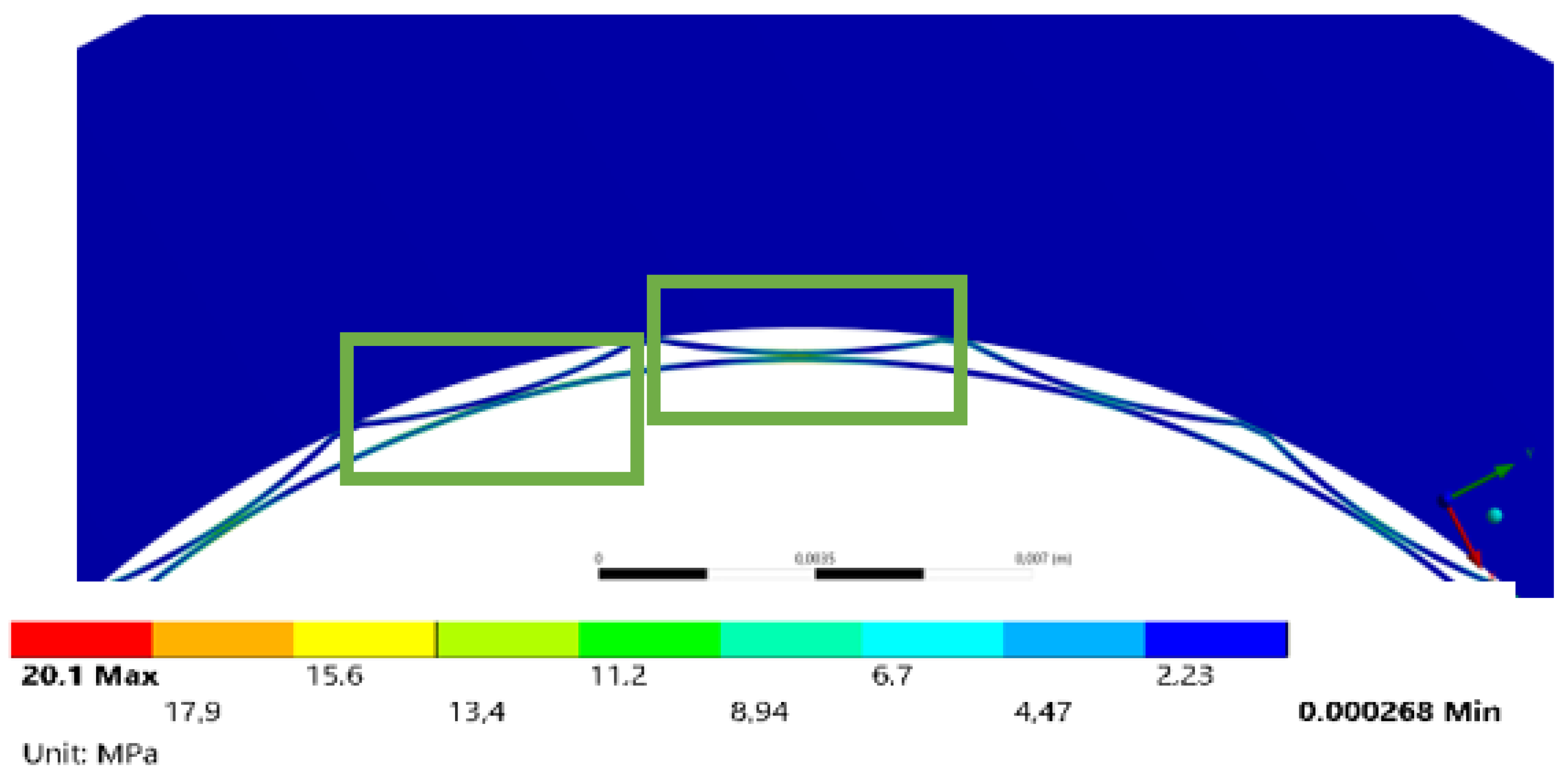
The calculations were performed using the static structural module of ANSYS Workbench (Figure 13), in which the bearing was divided into three parts. The sleeve was made of bronze, while the foils were made of Inconel 618. Frictional contact was applied between the top foil and the bump foil as well as between the bump foil and the sleeve and the friction coefficient was 0.2. The remaining contact parameters had default values. The computational mesh was created using HEX20 elements. The foils consisted of two elements along their thickness. The total number of finite elements was 24,344. The geometric clearances between the bearing components did not exceed 0.001 µm. All degrees of freedom on the outer surface of the bearing sleeve were fixed.
A pressure of 8000 Pa, was applied to the inner surface of the top foil. This pressure reflects the operating conditions associated with the lubricating film of the gas bearing. The height of one of the bump foils decreased by 12 µm compared to other bumps. The change in the geometry resulted in higher stresses of the remaining bumps (which increased by approximately 20 MPa). It is not possible to observe dynamic phenomena related to non-uniform bending of foil bumps using only classic displacement sensors (i.e., laser or eddy current sensors). The use of a high-speed camera in measurements enables experimental verification of phenomena that have been already analysed numerically. In the graph showing the experimental results, bigger changes in the displacement of the first bump in comparison to the second bump are marked by more red dots placed on the first bump than on the second one. In the graph showing the simulation results, bigger changes in the displacement of the first bump in comparison to the second bump correspond to higher stress values. By modelling the bumps with their proper heights, we are able to verify the experimental results.
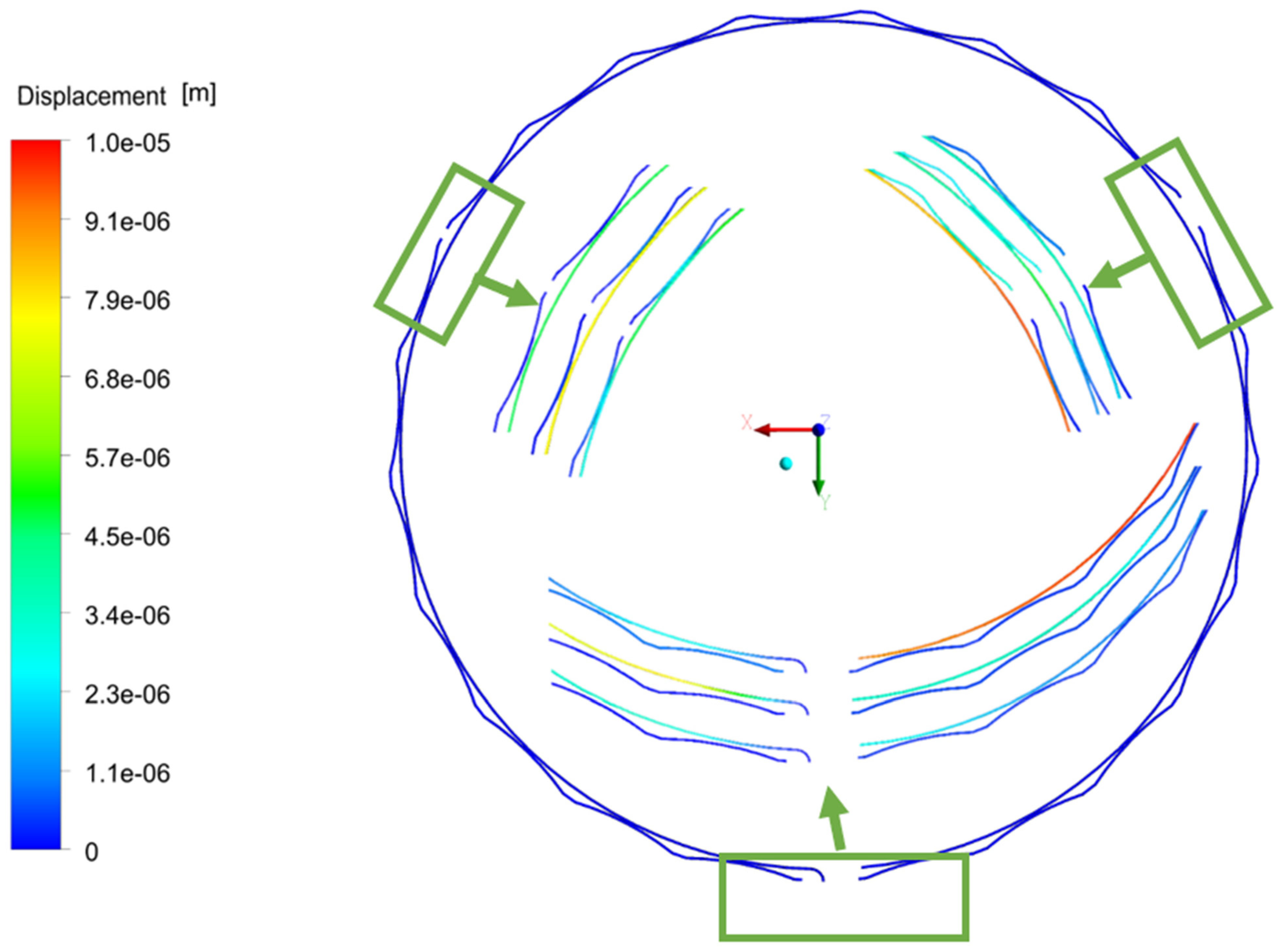
Another example showing how foils vibrate is shown in Figure 14. This figure shows three areas where the foil movements are particularly visible. In each of the areas, the displacements are shown at three different moments. It turns out that at individual moments the differences in displacements can be very large. Similar results were observed in experimental research.
5. Conclusions
Within the framework of the research presented herein, we conducted a visual analysis of displacements of the foil bearing’s subassemblies during stable operation of the rotating system and at two different dynamic loads. This method of examining the characteristics of foil bearings has not been used by other researchers so far. A video recording made using a set including only an ultra-high-speed camera and a macro lens did not allow a high enough magnification to be achieved to see details on the foils. Therefore, it was not possible to use it for analysing the motion of components of the foil bearing during its operation. Nevertheless, we also used two sets of extension tubes during our research. They allowed increasing the distance between the lens and the CMOS sensor, thus decreasing the minimum focusing distance and increasing the reproduction ratio. The distance between the lens and the CMOS sensor was increased by 128 mm. As a result of using these accessories, two or three bumps of the bump foil were visible in each display frame. The magnification was high enough to analyse their motion and observe portions of the bearing.
We observed different sections of the bearing (i.e., its top part, side part, and lock). Recordings presented various regimes such as the stable operation of the bearing at the nominal speed, the beginning of the operation, and run-up (during which the rotational speed was increased gradually). We also carried out several tests that aimed at checking the behaviour of the bearing after it was subjected to different impulse excitations. Depending on the magnitude of the excitation force, the bearing was able to function normally again (if the impact was not substantial) or plastic deformation of its structural supporting layer occurred (after a strong impact). It is worth noting that the bearing still operated after plastic deformation occurred, but its operating characteristics changed.
During the research, we noticed something interesting, namely the vibration of the bumps and portion of the top foil, which was located between bumps of the bump foil. This phenomenon has already been observed in numerical studies, and this is the first time it has been observed in experimental investigations. During operation at the maximum rotational speed (24,000 rpm), the vibration frequency of the top foil was equal to the frequency corresponding to the current rotational speed. By using the visual method in the analysis of the foil bearing’s supporting layer, we were able to assess the quality of the foil (and check if the bearing operated properly) and also to estimate the size of the area where the lubricating film formed itself. It was also possible to estimate the thickness of the lubricating film, which could have been very difficult or even impossible using other methods.
Author Contributions
Conceptualization, G.Ż.; methodology, G.Ż. and Ł.B.; validation, P.B.; formal analysis, Ł.B.; investigation, Ł.B. and P.B.; resources, G.Ż.; writing—original draft preparation, Ł.B.; writing—review and editing, G.Ż. and P.B.; supervision, G.Ż.; project administration, G.Ż.; funding acquisition, G.Ż. All authors have read and agreed to the published version of the manuscript.
Funding
The research presented in this article was carried out within the framework of project No. 2016/21/D/ST8/01711, entitled “Examination and modelling of anti-vibration processes occurring in high-speed bearings with variable geometry”, which is financed by the National Science Centre (NCN) in Poland. The research was conducted using the equipment of KEZO research centre in Jablonna.
Institutional Review Board Statement
Not applicable.
Informed Consent Statement
Not applicable.
Data Availability Statement
Not applicable.
Conflicts of Interest
The authors declare no conflict of interest.
References
- Ku, C.P.R.; Heshmat, H. Structural stiffness and coulomb damping in compliant foil journal bearings: Theoretical considerations. Tribol. Trans. 1994, 37, 525–533. [Google Scholar] [CrossRef]
- Rubio, D.; San Andres, L. Structural stiffness, dry friction coefficient, and equivalent viscous damping in a bump-type foil gas bearing. J. Eng. Gas Turbines Power 2007, 129, 494–502. [Google Scholar] [CrossRef]
- Conlon, M.J.; Dadouche, A.; Dmochowski, W.M.; Payette, R.; Bédard, J.-P. A Comparison of the Steady-State and Dynamic Performance of First- and Second-Generation Foil Bearings. In Proceedings of the ASME Turbo Expo 2010: Power for Land, Sea, and Air, Glasgow, UK, 14–18 June 2010; Volume 147, pp. 453–462. [Google Scholar]
- Bagiński, P.; Żywica, G.; Lubieniecki, M.; Roemer, J. The effect of cooling the foil bearing on dynamics of the rotor-bearings system. J. Vibroeng. 2018, 20, 843–857. [Google Scholar] [CrossRef]
- Żywica, G.; Bagiński, P.; Andrearczyk, A. Analysis of Thermal Damage in the High-Speed Foil Bearing. Solid State Phenom. 2017, 260, 266–277. [Google Scholar] [CrossRef]
- Kulkarni, S.; Jana, S. Influence of geometric parameters on the bump foil bearing performance. Proc. Inst. Mech. Eng. Part J J. Eng. Tribol. 2019, 234, 1017–1026. [Google Scholar] [CrossRef]
- Xu, F.; Sun, Y.; Zhang, G.; Liu, Z. Effect of bump structural friction on the performance of bump foil bearing and rotor dynamic behavior: Experimental study. Proc. Inst. Mech. Eng. Part J J. Eng. Tribol. 2019, 233, 702–711. [Google Scholar] [CrossRef]
- Bonello, P.; Hassan, M.F.B. An experimental and theoretical analysis of a foil-air bearing rotor system. J. Sound Vib. 2018, 413, 395–420. [Google Scholar] [CrossRef] [Green Version]
- Gu, Y.; Ma, Y.; Ren, G. Stability and vibration characteristics of a rotor-gas foil bearings system with high-static-low-dynamic-stiffness supports. J. Sound Vib. 2017, 397, 152–170. [Google Scholar] [CrossRef]
- Larsen, J.S.; Santos, I.F. On the nonlinear steady-state response of rigid rotors supported by air foil bearings-theory and experiments. J. Sound Vib. 2015, 346, 284–297. [Google Scholar] [CrossRef]
- Staudt, T.; Eschner, E.; Tenner, F.; Schmidt, M. Deriving spectral information upon the laser welding process employing a hyperspectral imaging technique. Procedia CIRP 2018, 74, 636–639. [Google Scholar] [CrossRef]
- Miles, R.B. Optical diagnostics for high-speed flows. Prog. Aerosp. Sci. 2015, 72, 30–36. [Google Scholar] [CrossRef]
- Wu, K.; Brueninghaus, J.; Johnen, B.; Kuhlenkoetter, B. Applicability of stereo high speed camera systems for robot dynamics analysis. In Proceedings of the 2015 International Conference on Control, Automation and Robotics, ICCAR 2015, Singapore, 20–22 May 2015; pp. 44–48. [Google Scholar]
- Liu, X.; Tong, X.; Lu, W.; Liu, S.; Huang, B.; Tang, P.; Guo, T. High-speed videogrammetric measurement of the deformation of shaking table multi-layer structures. Meas. J. Int. Meas. Confed. 2020, 154, 107486. [Google Scholar] [CrossRef]
- Znamenskaya, I.A.; Nersesyan, D.A.; Sysoev, N.N.; Koroteeva, E.Y.; Shirshov, Y.N. An optical study of high-pressure water-jet dynamics. Mosc. Univ. Phys. Bull. 2016, 71, 405–412. [Google Scholar] [CrossRef]
- Zeleňák, M.; Říha, Z.; Jandačka, P. Visualization and velocity analysis of a high-speed modulated water jet generated by a hydrodynamic nozzle. Meas. J. Int. Meas. Confed. 2020, 159, 1–9. [Google Scholar] [CrossRef]
- Hassan, M.A.; Malik, A.S.; Fofi, D.; Karasfi, B.; Meriaudeau, F. Towards health monitoring using remote heart rate measurement using digital camera: A feasibility study. Meas. J. Int. Meas. Confed. 2020, 149, 106804. [Google Scholar] [CrossRef]
- Sánchez-Pay, A.; Courel-Ibáñez, J.; Martínez-Cava, A.; Conesa-Ros, E.; Morán-Navarro, R.; Pallarés, J.G. Is the high-speed camera-based method a plausible option for bar velocity assessment during resistance training? Meas. J. Int. Meas. Confed. 2019, 137, 355–361. [Google Scholar] [CrossRef]
- Wang, L.L.; Lu, C.H. The effect of viscosity on the cavitation characteristics of high speed sleeve bearing. J. Hydrodyn. 2015, 27, 367–372. [Google Scholar] [CrossRef]
- Jacobson, B.O.; Hamrock, B.J. High-Speed Motion Picture Camera Experiments of Cavitation in Dynamically Loaded Journal Bearings. J. Lubr. Technol. 1983, 105, 446–452. [Google Scholar] [CrossRef] [Green Version]
- Tong, X.; Luan, K.; Liu, X.; Liu, S.; Chen, P.; Jin, Y.; Lu, W.; Huang, B. Tri-camera high-speed videogrammetry for three-dimensional measurement of laminated rubber bearings based on the large-scale shaking table. Remote Sens. 2018, 10, 1902. [Google Scholar] [CrossRef] [Green Version]
- Durand-Texte, T.; Melon, M.; Simonetto, E.; Durand, S.; Moulet, M.H. Single-camera single-axis vision method applied to measure vibrations. J. Sound Vib. 2020, 465, 115012. [Google Scholar] [CrossRef]
- Wang, X.; Guo, J.; Lu, S.; Shen, C.; He, Q. A computer-vision-based rotating speed estimation method for motor bearing fault diagnosis. Meas. Sci. Technol. 2017, 28, 65012. [Google Scholar] [CrossRef]
- Köhl, W.; Kreschel, M.; Filsinger, D. Experimental and Numerical Investigations on an Automotive Turbocharger with a Transparent Bearing Section. In Institution of Mechanical Engineers—11th International Conference on Turbochargers and Turbocharging; Woodhead Publishing Limited: Cambridge, UK, 2014. [Google Scholar]
- Łagodziński, J.; Miazga, K. Influence of intermediate foil on air-foil bearings performance and exploitation properties. Adv. Tech. Diagn. 2018, 10, 401–410. [Google Scholar]
- Bagiński, P.; Żywica, G. Research of the influence of long-lasting cyclic loading on the geometry of the bump foil of a gas foil bearing. Tribologia 2019, 284, 5–13. [Google Scholar] [CrossRef]
- San Andrés, L.; Kim, T.H. Analysis of gas foil bearings integrating FE top foil models. Tribol. Int. 2009, 42, 111–120. [Google Scholar] [CrossRef]
- Hoffmann, R.; Liebich, R. Characterisation and calculation of nonlinear vibrations in gas foil bearing systems—An experimental and numerical investigation. J. Sound Vib. 2018, 412, 389–409. [Google Scholar] [CrossRef]
Figure 1.
Test rig with a foil bearing and a computer-controlled camera.

Figure 2.
Scheme of the measurement setup.

Figure 3.
Scheme showing how the foil bearing is mounted on the shaft.

Figure 4.
Vision Research’s v2511 ultrahigh-speed camera (left). Extension tubes that enable achieving higher macro magnification (right).
Figure 4.
Vision Research’s v2511 ultrahigh-speed camera (left). Extension tubes that enable achieving higher macro magnification (right).

Figure 5.
Point used to analyse the displacement (on the bump foil).

Figure 6.
Displacement of the foil at a rotational speed of 24,000 rpm. One bump is not manufactured perfectly.
Figure 6.
Displacement of the foil at a rotational speed of 24,000 rpm. One bump is not manufactured perfectly.

Figure 7.
Displacement of the foil at a rotational speed of 24,000 rpm.

Figure 8.
Point on the surface of the sleeve, which was used to perform a displacement analysis when a small excitation force was applied to the bearing (indicated by green arrow).
Figure 8.
Point on the surface of the sleeve, which was used to perform a displacement analysis when a small excitation force was applied to the bearing (indicated by green arrow).

Figure 9.
Displacement of the bearing to which a small excitation force was applied.

Figure 10.
Maximum deflection of the foils caused by an impulse excitation (left). Stable operation of the bearing (right).
Figure 10.
Maximum deflection of the foils caused by an impulse excitation (left). Stable operation of the bearing (right).

Figure 11.
Displacement of the bearing to which a high excitation force was applied.

Figure 12.
Picture recorded using a high-speed camera (left). The changes between the two extreme journal positions are marked in red (right).
Figure 12.
Picture recorded using a high-speed camera (left). The changes between the two extreme journal positions are marked in red (right).

Figure 13.
Model of foil bearing with unequal bumps.

Figure 14.
Changes of foil displacements.

Publisher’s Note: MDPI stays neutral with regard to jurisdictional claims in published maps and institutional affiliations. |
© 2021 by the authors. Licensee MDPI, Basel, Switzerland. This article is an open access article distributed under the terms and conditions of the Creative Commons Attribution (CC BY) license (http://creativecommons.org/licenses/by/4.0/).
Share and Cite
MDPI and ACS Style
Breńkacz, Ł.; Bagiński, P.; Żywica, G. Experimental Research on Foil Vibrations in a Gas Foil Bearing Carried Out Using an Ultra-High-Speed Camera. Appl. Sci. 2021, 11, 878. https://0-doi-org.brum.beds.ac.uk/10.3390/app11020878
AMA Style
Breńkacz Ł, Bagiński P, Żywica G. Experimental Research on Foil Vibrations in a Gas Foil Bearing Carried Out Using an Ultra-High-Speed Camera. Applied Sciences. 2021; 11(2):878. https://0-doi-org.brum.beds.ac.uk/10.3390/app11020878
Chicago/Turabian StyleBreńkacz, Łukasz, Paweł Bagiński, and Grzegorz Żywica. 2021. "Experimental Research on Foil Vibrations in a Gas Foil Bearing Carried Out Using an Ultra-High-Speed Camera" Applied Sciences 11, no. 2: 878. https://0-doi-org.brum.beds.ac.uk/10.3390/app11020878
Note that from the first issue of 2016, this journal uses article numbers instead of page numbers. See further details here.