A Theoretical Method for Designing Thin Wobble Motor Using an Electromagnetic Force and an Electropermanent Magnet for Application in Portable Electric Equipment

Abstract
:1. Introduction
2. Driving Principle and Structure
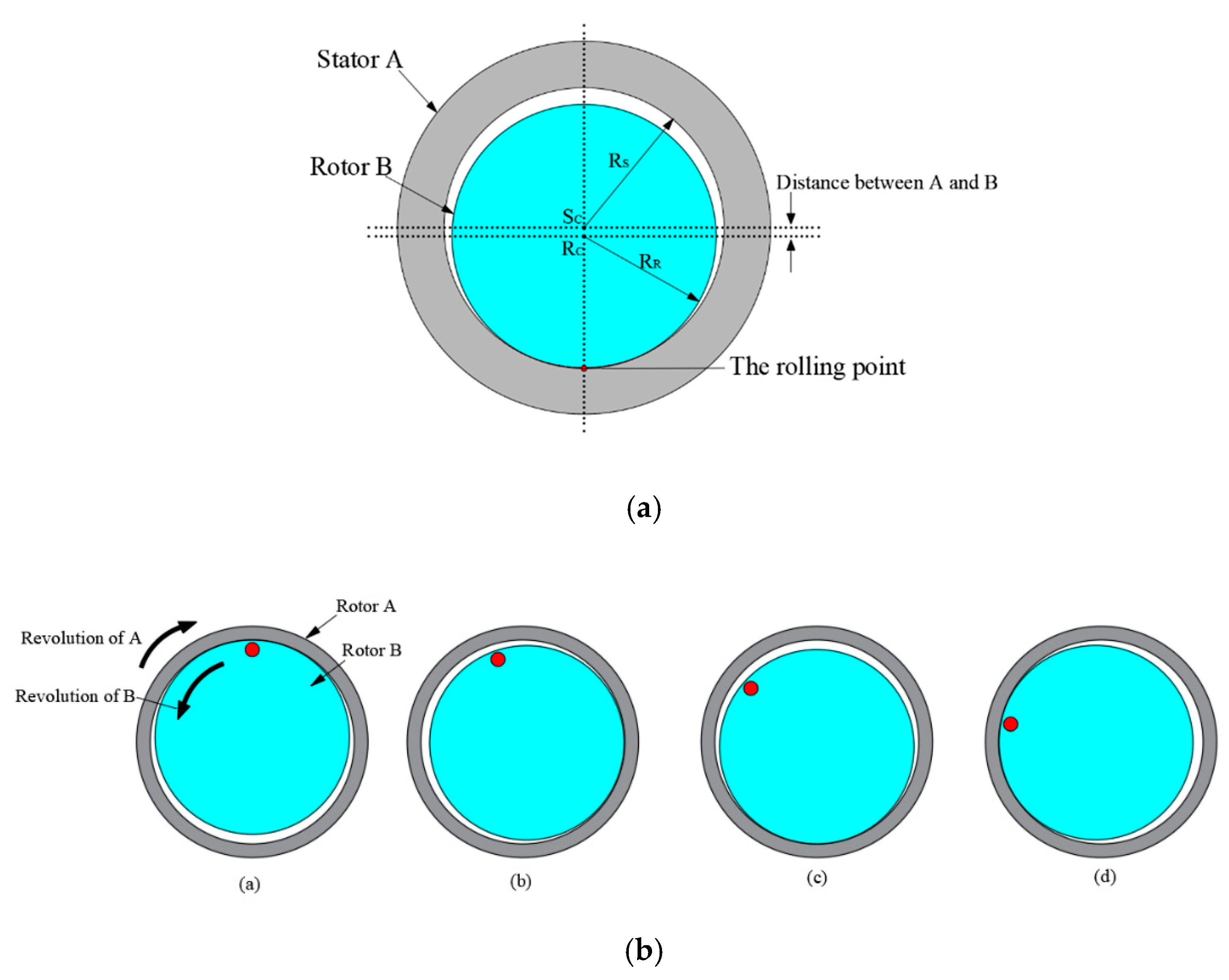
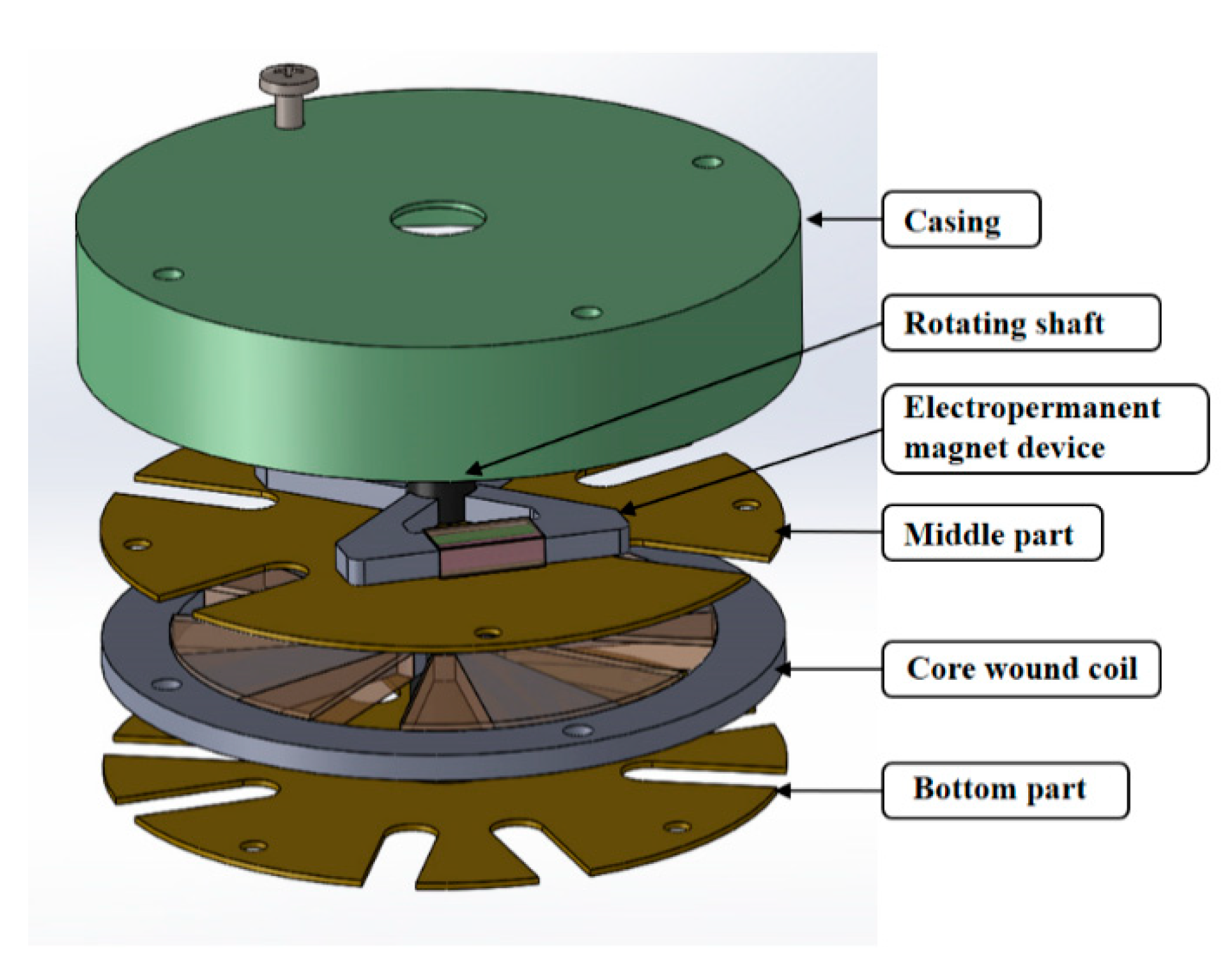
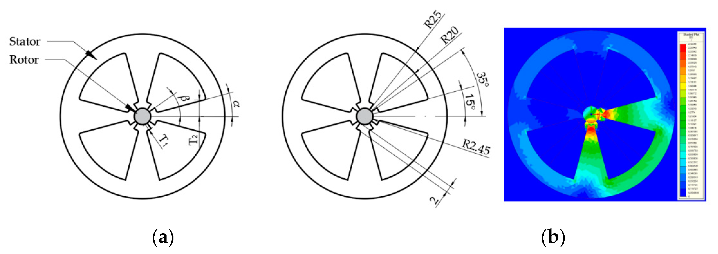
2.1. Driving Principle and Structure of the Wobble Motor
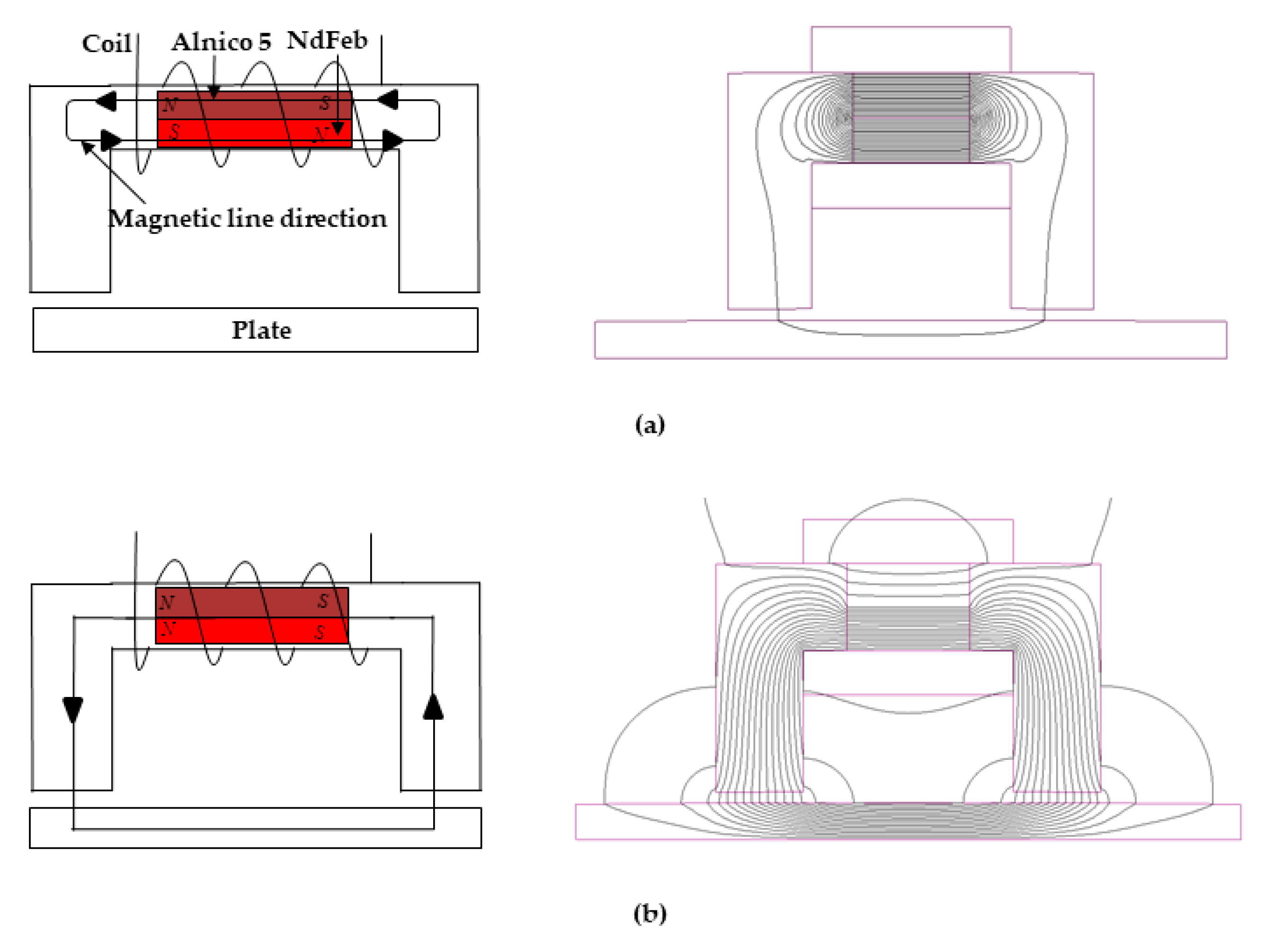
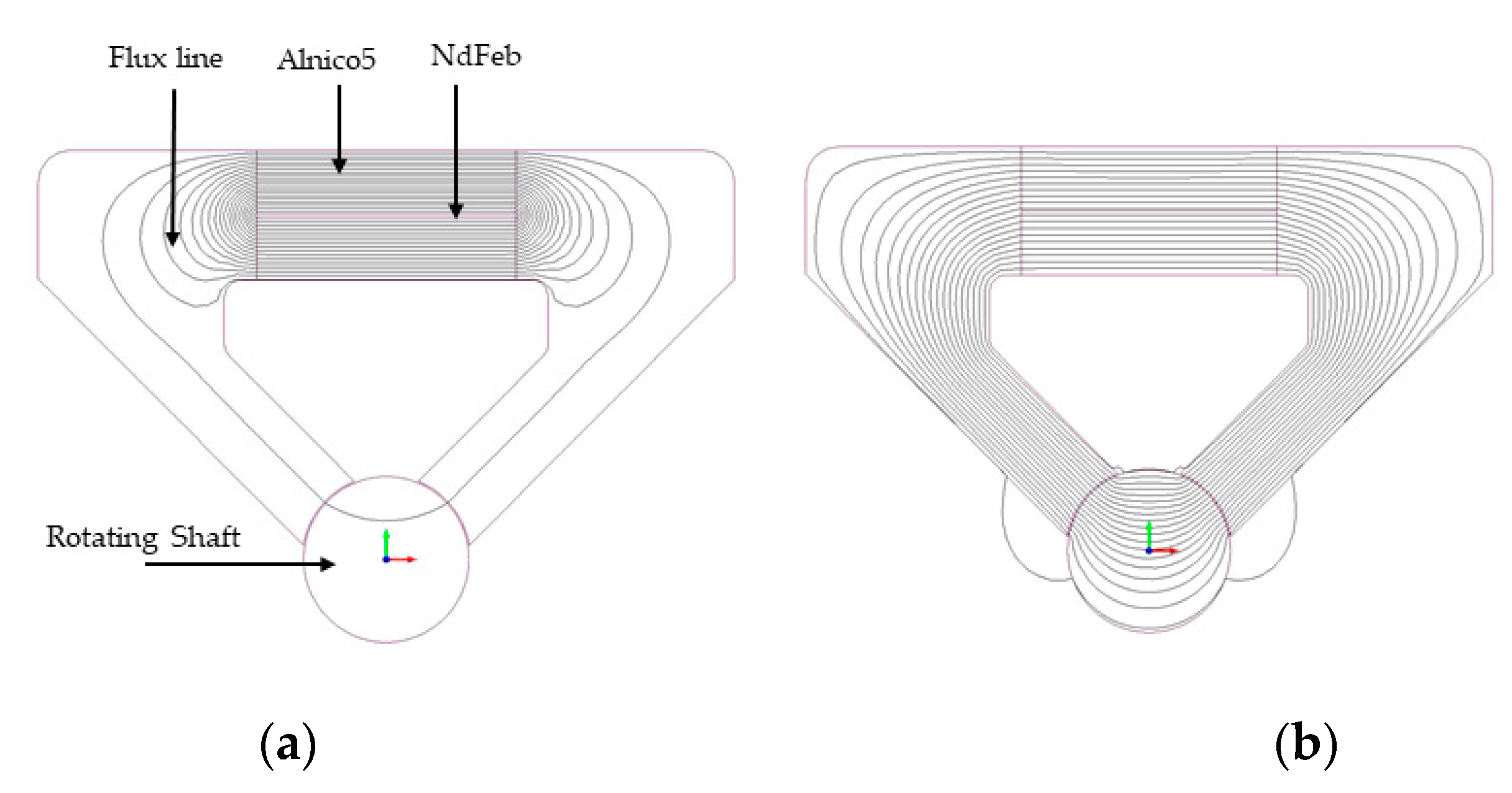
2.2. Driving Principle and Structure of the EPM
3. Derivation of Theoretical Force Model
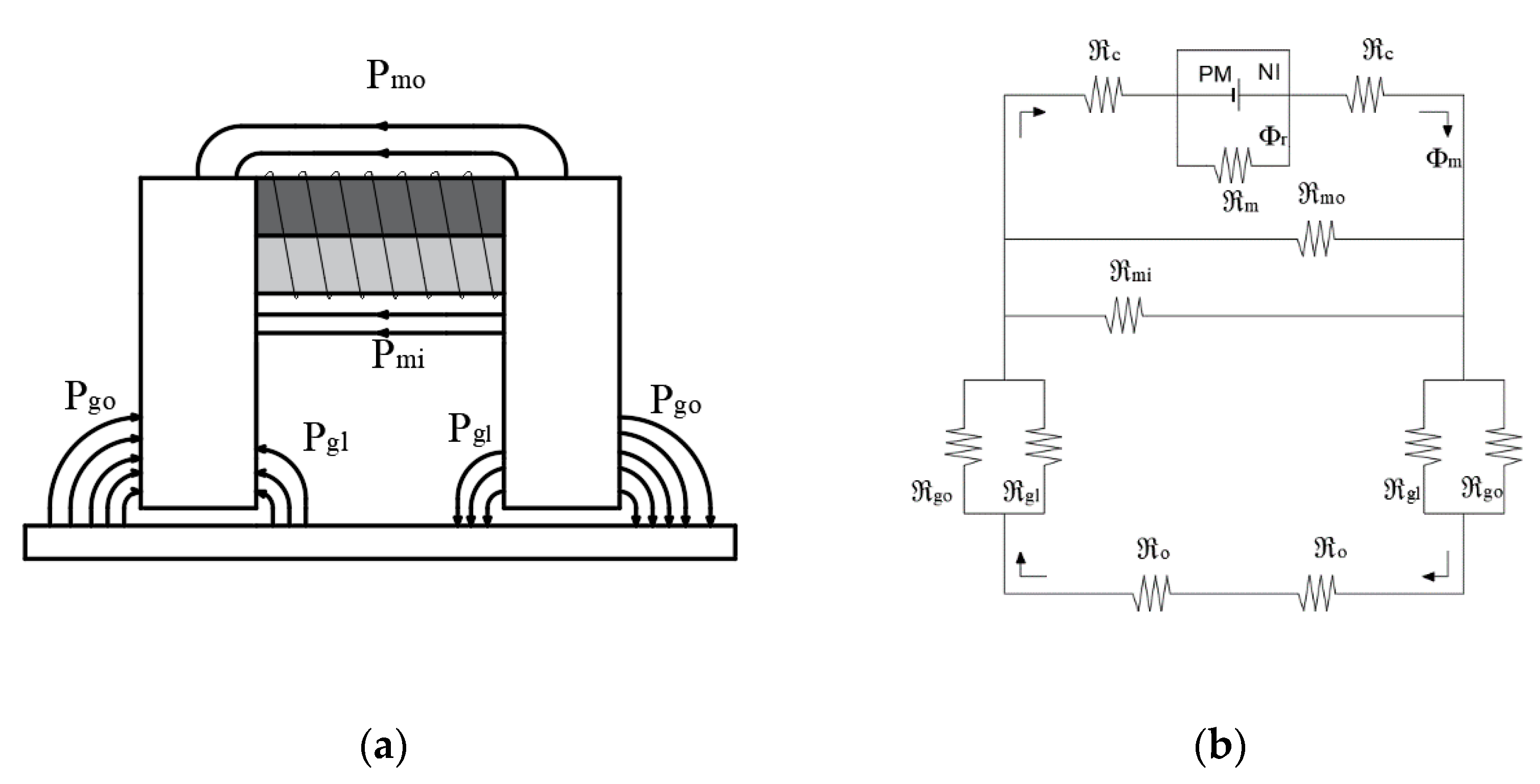
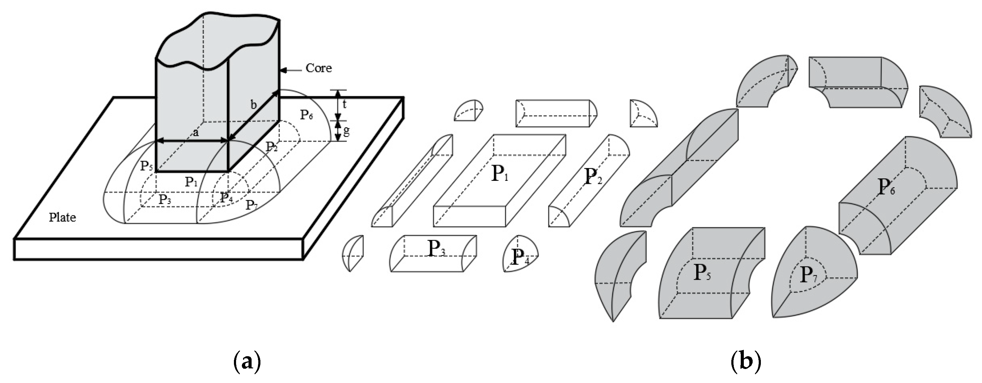
3.1. Theoretical Force Analysis of the EPM
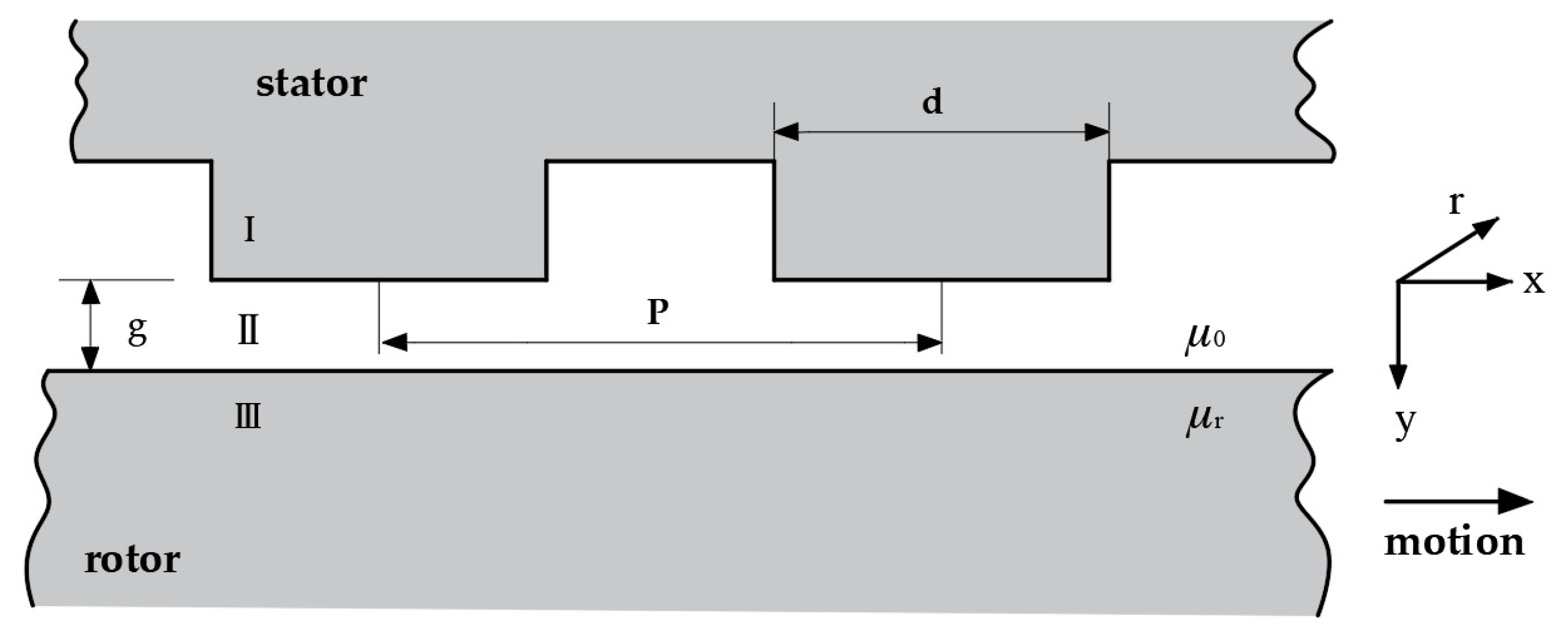
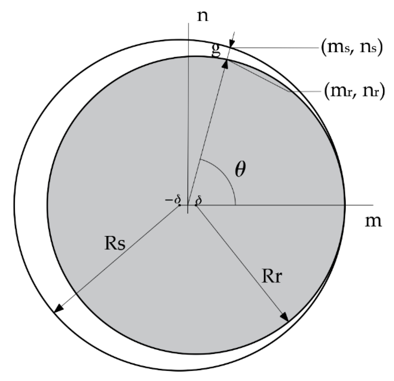
3.2. Theoretical Force Analysis of Motor
4. Validation of Theoretical Force Model
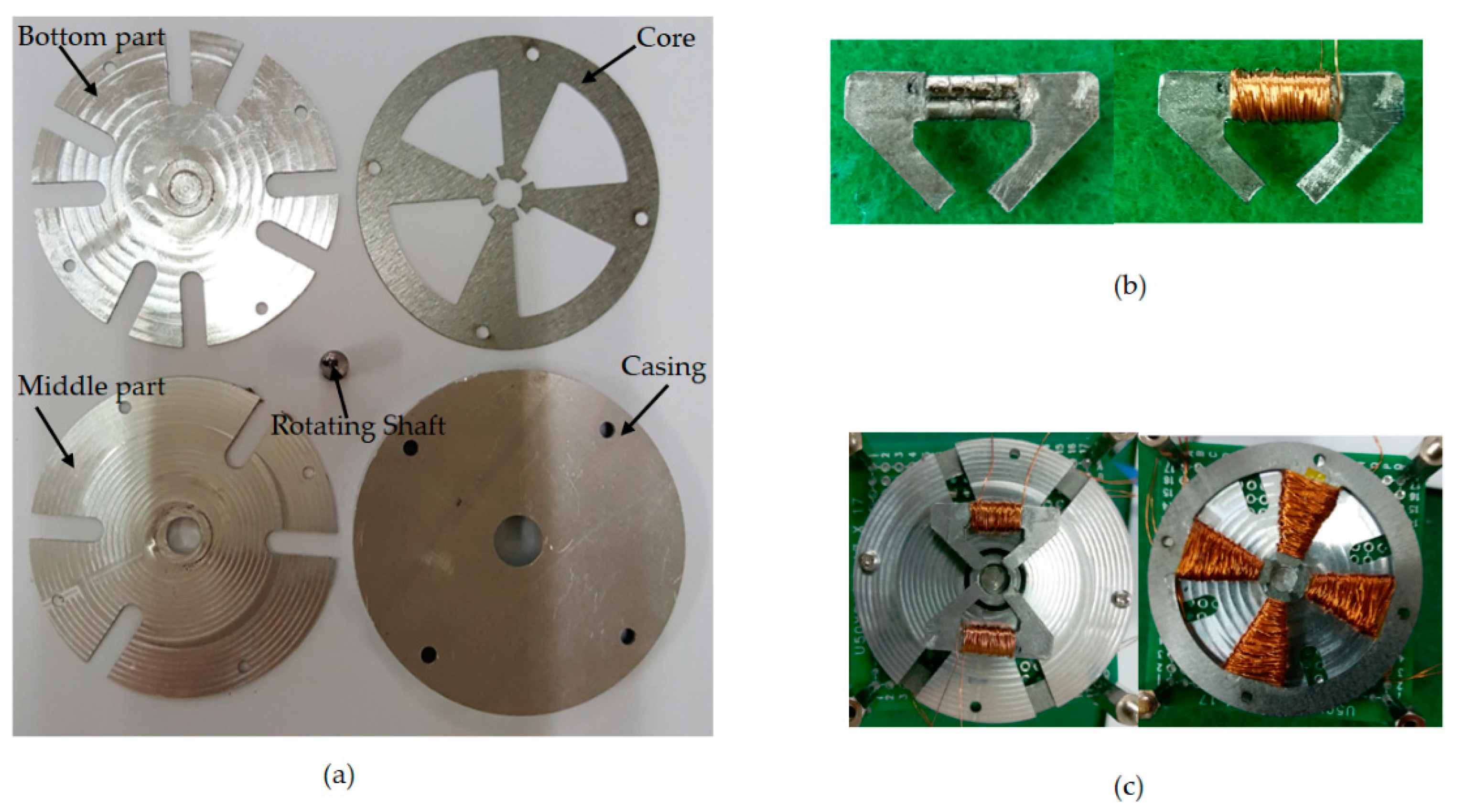
4.1. Modeling and Structure of Motor with EPM
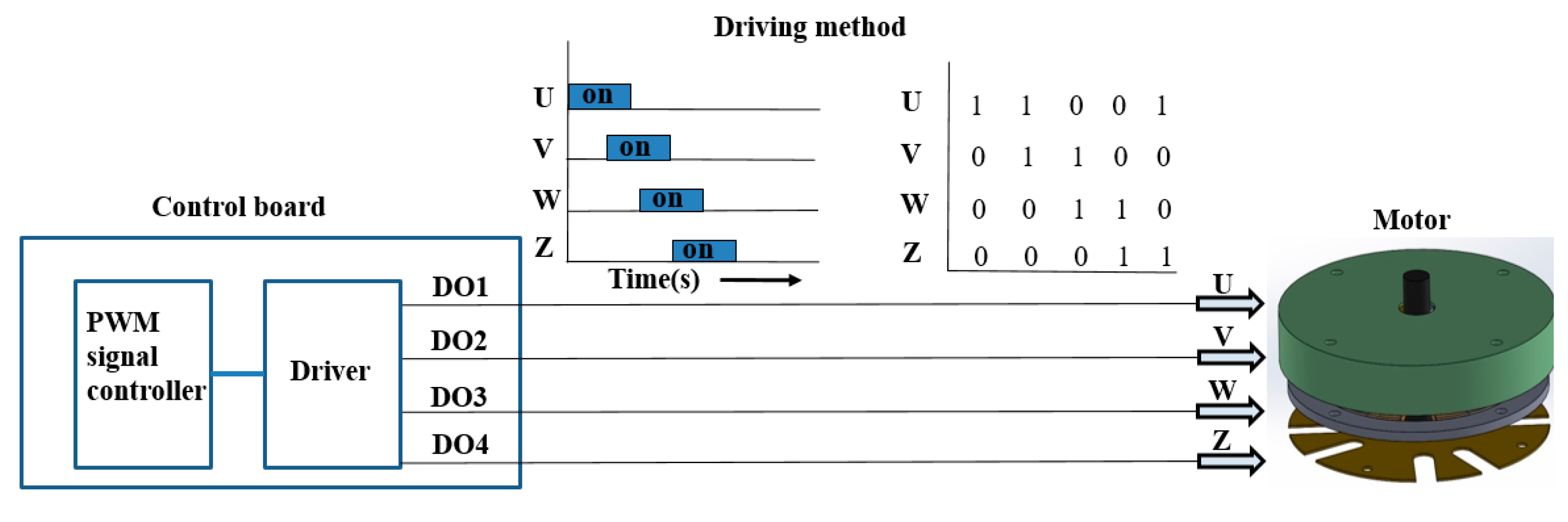
4.2. Experimental System and Driving Principle
4.3. Experiment for Theoretical Model Validation
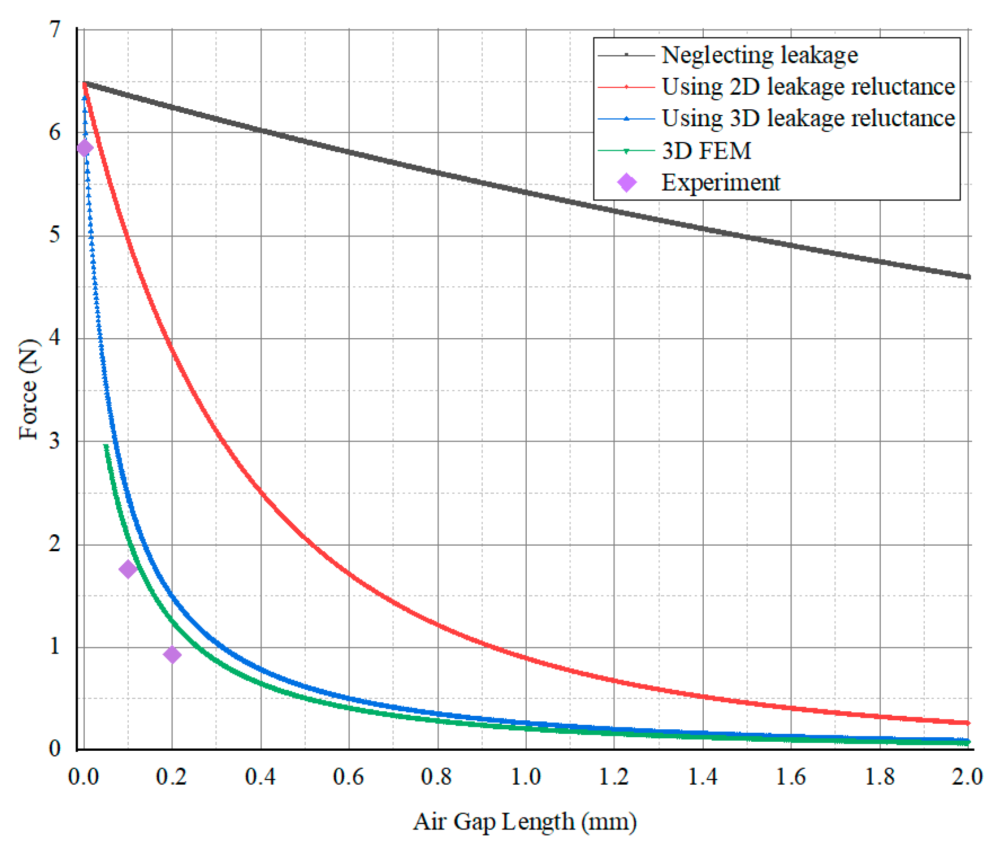
4.4. Validation Results
5. Conclusions
Author Contributions
Funding
Institutional Review Board Statement
Informed Consent Statement
Data Availability Statement
Conflicts of Interest
Abbreviation
| EPM | Electropermanent Magnet |
References
- Viviani, A. Experimental and Theoretical Study of Hypocycloidal Motors with Two-Harmonic Field Windings. IEEE Trans. Power Appar. Syst. 1980, 1, 292–300. [Google Scholar]
- Hayashi, I.; Iwatsuki, N.; Shibata, J.; Matsunaga, H.; Wada, S. An Electromagnetic Cycloid Motor. J. Jpn. Soc. Precis. Eng. 1995, 61, 95–99. [Google Scholar] [CrossRef]
- Nagata, T.; Suzumori, K.; Kanda, T.; Uzuka, K.; Enomoto, I. Electro Direct-Drive Stepping Motor for Robots. In Proceedings of the IEEE International Conference on Robotics and Automation, New Orleans, LA, USA, 26 April–1 May 2004; pp. 4493–4498. [Google Scholar]
- Kimura, H.; Hirose, S.; Nakaya, K. Development of the Crown Motor. In Proceedings of the 2001 ICRA, IEEE International Conference on Robotics and Automation, Seoul, Korea, 21–26 May 2001; pp. 2442–2447. [Google Scholar]
- Okamoto, K.; Suzumori, K.; Kanda, T.; Yamada, Y. Development of Three-Chamber Micro Pneumatic Wobble Motor. Proc. Mach. Des. Tribol. Div. 2006, 295–297. [Google Scholar] [CrossRef]
- De Cristofaro, S.; Stefanini, C.; Ng Pak, N.; Susilo, E.; Carrozza, M.C.; Dario, P. Electromagnetic wobble micromotor for microrobots actuation. Sens. Actuators A Phys. 2010, 161, 234–244. [Google Scholar] [CrossRef]
- Jacobsen, S.C.; Price, R.H.; Wood, J.E.; Rytting, T.H.; Rafaelof, M. The Wobble Motor: Design, Fabrication and Testing of an Eccentric-Motion Electrostatic Microactuator. In Proceedings of the IEEE International Conference on Robotics and Automation, Scottsdale, AZ, USA, 14–19 May 1989; pp. 1536–1546. [Google Scholar]
- Suzumori, K.; Hori, K. Micro Electrostatic Wobble Motor with Toothed Electrodes. In Proceedings of the IEEE Tenth Annual International Workshop, Nagoya, Japan, 26–30 January 1997; pp. 227–232. [Google Scholar]
- Miyake, M.; Suzumori, K.; Uzuka, K. Development of a Thin Electromagnetic Wobble Motor. In Proceedings of the 2011 IEEE International Conference on Robotics and Biomimetics, Karon Beach, Phuket, Thailand, 7–11 December 2011; pp. 2523–2528. [Google Scholar]
- Jacobsen, S.C.; Price, R.H.; Wood, J.E.; Rytting, T.H.; Rafaelof, M. The Wobble Motor: An Electrostatic, Planetary-Armature, Microactuator. In Proceedings of the IEEE Micro Electro Mechanical Systems, An Investigation of Micro Structures, Sensors, Actuators, Machines and Robots, Salt Lake City, UT, USA, 20–22 February 1989. [Google Scholar]
- Jungreis, A.M.; Kelley, A.W. The axial air gap wobble motor—An appropriate topology for magnetic micromotors. In Proceedings of the Conference Record of the 1995 IEEE Industry Applications Conference Thirtieth IAS Annual Meeting, Orlando, FL, USA, 8–12 October 1995. [Google Scholar]
- Mehergancy, M.; Nagarkar, P.; Senturia, S.D.; Lang, J.H. Operation of Microfabricated Harmonic and Ordinary Side-Drive Motors. In Proceedings of the IEEE Proceedings on Micro Electro Mechanical Systems, An Investigation of Micro Structures, Sensors, Actuators, Machines and Robots, Napa Valley, CA, USA, 11–14 February 1990. [Google Scholar]
- Dhuler, V.R.; Mehregany, M.; Phillips, S.M. An experimental technique and a model for studying the operation of harmonic side-drive micromotors. IEEE Trans. Electron Devices 1993, 40, 1977–1984. [Google Scholar] [CrossRef]
- Deng, K.; Meheregany, M. Outer-Rotor Polysilicon Wobble Micromotors. In Proceedings of the IEEE Workshop on Micro Electromechanical Systems, Oiso, Japan, 25–28 January 1994. [Google Scholar]
- Furuhata, T.; Hirano, T.; Lane, L.H.; Fontana, R.E.; Fan, L.S.; Fujita, H. Outer Rotor Surface-Micromachined Wobble Micromotor. In Proceedings of the IEEE Micro Electro Mechanical Systems, Fort Lauderdale, FL, USA, 10 February 1993. [Google Scholar]
- Ewing, J.A.; Klaassen, H.G. Magnetic qualities of Iron. Philos. Trans. R. Soc. A 1893, 184, 985–1039. [Google Scholar]
- Campbell, P.; Al-Murshid, S. A model of anisotropic Alnico magnets for field Computation Magnetics. IEEE Trans. Magn. 1982, 18, 898–904. [Google Scholar] [CrossRef]
- Hanselman, D.C. Brushless Permanent Magnet Motor Design; McGraw-Hill: Cranston, RI, USA, 1994. [Google Scholar]
- Roters, H.C. Electromagnetic Devices, 1st ed.; John Wiley & Sons: New York, NY, USA, 1941. [Google Scholar]
- Yamamura, S. Theory of Linear Induction Motors, 2nd ed.; Wiley: New York, NY, USA, 1979. [Google Scholar]
- Wangsness, R.K. Electromagnetic Fields, 2nd ed.; Wiley: New York, NY, USA, 1986. [Google Scholar]
- Griffiths, D.J. Introduction to Electrodynamics, 2nd ed.; Prentice Hall: Upper Saddle River, NJ, USA, 1989. [Google Scholar]
- Nasar, S.A. Linear Motion Electric Machines; John Wiley & Sons: New York, NY, USA, 1976. [Google Scholar]
- Trimmer, W.; Jebens, R. An Operational Harmonic Electrostatic Motor. In Proceedings of the IEEE Micro Electro Mechanical Systems, An Investigation of Micro Structures, Sensors, Actuators, Machines and Robots, Salt Lake City, UT, USA, 20–22 February 1989; pp. 13–16. [Google Scholar]


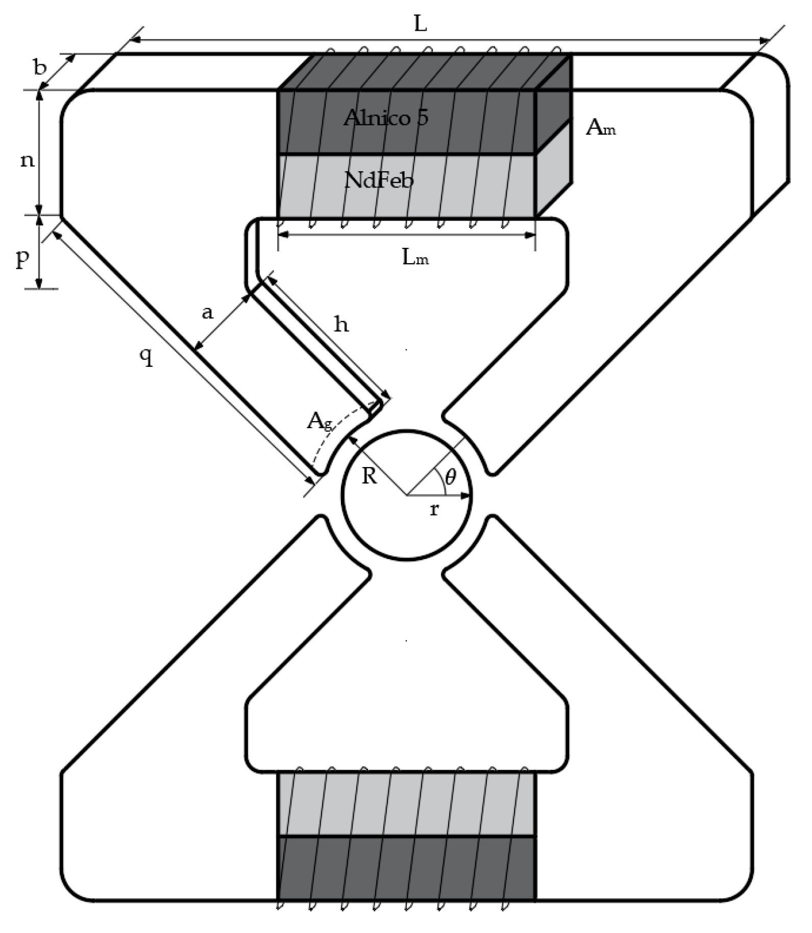
| Parameter | Symbol | Value | Unit |
|---|---|---|---|
| Thickness | b | 2 | mm |
| Length | L | 22 | mm |
| Pole length | n | 4 | mm |
| Pole length | q | 11.6 | mm |
| Pole length | h | 5.5 | mm |
| Pole height | p | 2 | mm |
| Pole width | a | 2 | mm |
| Magnet diameter | d | 2 | mm |
| Magnet length | Lm | 8 | mm |
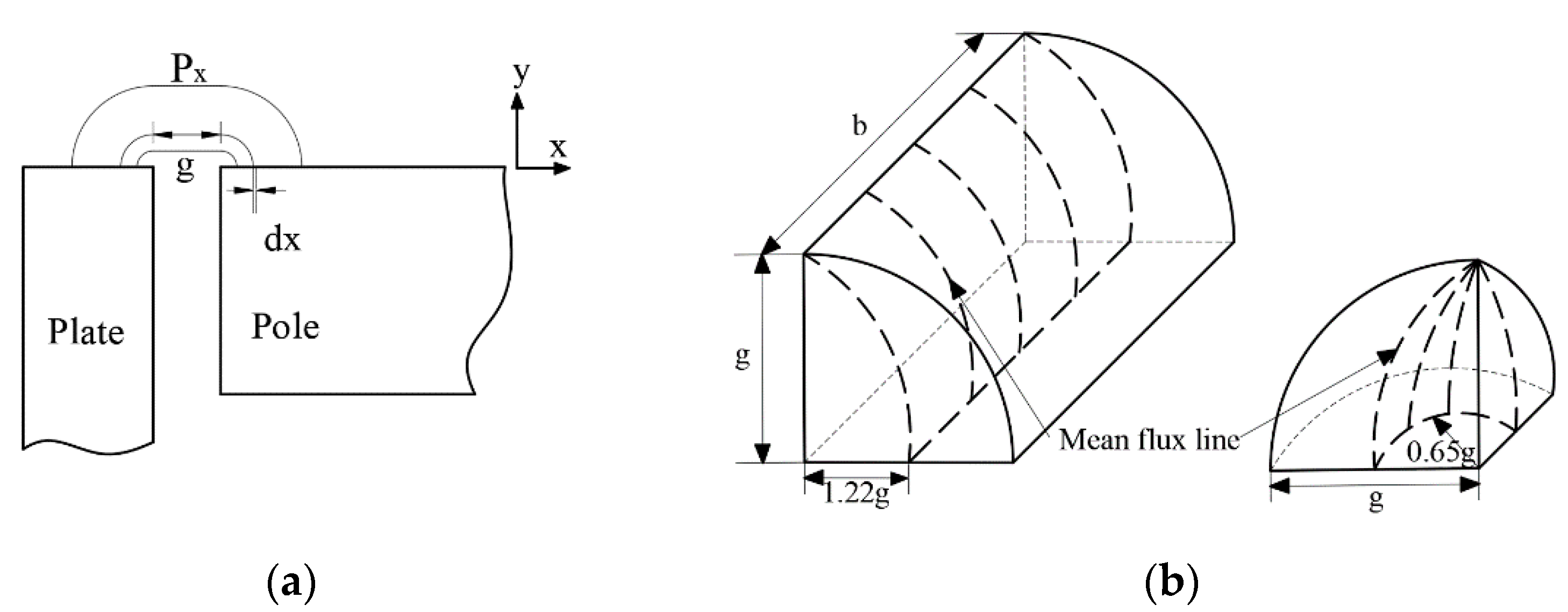
| Air gap | g | 0.1 | mm |
| Rotor diameter | r | 5 | mm |
| Stator diameter | R | 5.1 | mm |
| Number of turns | N | 120 | |
| Angle | 45 | deg | |
| Applied larger than current | i | 5 | A |
| Diameter of the coil | dc | 0.18 | mm |
| Permeability of the free space | H/m | ||
| Relative permeability of the magnet | 1.05 | H/m | |
| Cross-sectional area of the air gap | 5.26 | ||
| Cross-sectional area of two magnets | 6.28 |
| Current (A) | By Theoretical Method (mNm) | By FEM (mNm) | By Experiment (mNm) |
|---|---|---|---|
| 0.1 | 0.166 | 0.134 | 0.118 |
| 0.2 | 0.672 | 0.523 | 0.456 |
| 0.3 | 1.488 | 1.173 | 1.034 |
| 0.4 | 2.64 | 2.088 | 1.843 |
| 0.5 | 4.128 | 3.264 | 2.857 |
Publisher’s Note: MDPI stays neutral with regard to jurisdictional claims in published maps and institutional affiliations. |
© 2021 by the authors. Licensee MDPI, Basel, Switzerland. This article is an open access article distributed under the terms and conditions of the Creative Commons Attribution (CC BY) license (http://creativecommons.org/licenses/by/4.0/).
Share and Cite
Park, S.Y.; Song, B.; Baek, Y.S. A Theoretical Method for Designing Thin Wobble Motor Using an Electromagnetic Force and an Electropermanent Magnet for Application in Portable Electric Equipment. Appl. Sci. 2021, 11, 881. https://0-doi-org.brum.beds.ac.uk/10.3390/app11020881
Park SY, Song B, Baek YS. A Theoretical Method for Designing Thin Wobble Motor Using an Electromagnetic Force and an Electropermanent Magnet for Application in Portable Electric Equipment. Applied Sciences. 2021; 11(2):881. https://0-doi-org.brum.beds.ac.uk/10.3390/app11020881
Chicago/Turabian StylePark, Sang Yong, Buchun Song, and Yoon Su Baek. 2021. "A Theoretical Method for Designing Thin Wobble Motor Using an Electromagnetic Force and an Electropermanent Magnet for Application in Portable Electric Equipment" Applied Sciences 11, no. 2: 881. https://0-doi-org.brum.beds.ac.uk/10.3390/app11020881