Article

Phononic Band Gap and Free Vibration Analysis of Fluid-Conveying Pipes with Periodically Varying Cross-Section

College of Mechanical Engineering, Yangzhou University, Yangzhou 225127, China
*
Author to whom correspondence should be addressed.
Submission received: 13 September 2021 / Revised: 26 October 2021 / Accepted: 1 November 2021 / Published: 8 November 2021
(This article belongs to the Special Issue Vibration Control and Applications)

Abstract

:
Phononic crystals (PCs) are a novel class of artificial periodic structure, and their band gap (BG) attributes provide a new technical approach for vibration reduction in piping systems. In this paper, the vibration suppression performance and natural properties of fluid-conveying pipes with periodically varying cross-section are investigated. The flexural wave equation of substructure pipes is established based on the classical beam model and traveling wave property. The spectral element method (SEM) is developed for semi-analytical solutions, the accuracy of which is confirmed by comparison with the available literature and the widely used transfer matrix method (TMM). The BG distribution and frequency response of the periodic pipe are attained, and the natural frequencies and mode shapes are also obtained. The effects of some critical parameters are discussed. It is revealed that the BG of the present pipe system is fundamentally induced by the geometrical difference of the substructure cross-section, and it is also related to the substructure length and fluid–structure interaction (FSI). The number of cells does not contribute to the BG region, while it has significant effects on the amplitude attenuation, higher order natural frequencies and mode shapes. The impact of FSI is more evident for the pipes with smaller numbers of cells. Moreover, compared with the conventional TMM, the present SEM is demonstrated more effective for comprehensive analysis of BG characteristics and free vibration of PC dynamical structures.

1. Introduction

Fluid-conveying pipes are a typical class of device for storing and carrying fluids, which have served extensively in many fields of modern industry and daily life. The dynamical performance of fluid-conveying pipes has received considerable attention over the past decades, due to its engineering significance and academic value. The conventional studies on the fluid-conveying pipes mainly focus on the instability caused by the fluid–structure interaction (FSI) [1]. It is shown that when the internal fluid flows at a higher velocity [2] or with some disturbance [3], the pipe may get buckled or vibrate strongly, which will produce heave noise, cause fatigue and damage of the pipe, and further threaten the safety of surrounding equipment. Therefore, it is of great importance to explore vibration suppression strategies for such engineering structures.
As an emerging discipline, the phononic theory has triggered increasing interest in recent years. Various dynamical structures based on phononic crystals (PCs) and acoustic metamaterials (AMs) have been designed to attenuate elastic waves and suppress vibrations. These structures are mainly characterized by the periodic arrangement of substructures since the impedance mismatch of substructures will block propagating waves, that is, form the phononic band gap (BG). In particular, the band structure of such functional composites can be tuned artificially, which will benefit their application in a wide range of frequencies. It is well-known that the PC theory is quite related to the origami structures [4]. Inspired by this innovative idea, Yang et al. [5] and Yang et al. [6] proposed a real-time BG modulation technique for one- and two-dimensional spring-mass systems based on parametric excitations. Salari-Sharif et al. [7] realized the metamaterials with tunable BGs by introducing periodically arranged negative-stiffness inclusions. Qian et al. [8] considered manipulating transverse waves using longitudinal vibrations, which in essence provide a pseudo-stiffness. Miao et al. [9] designed a new periodic composite with quasi-phononic crystals, which can open the ultra-low frequency BG. Panahi et al. [10] proposed two novel phononic unit-cells and demonstrated that they can provide over 200% BG coverage factor over the low-frequency range of 0–12 kHz. Experiment was also conducted to validate the BGs of PC pipes [11]. Furthermore, acoustic black hole (ABH) models were concerned to adjust the BGs of PCs and AMs [12,13,14,15], and periodic tubular structures were used to design PC sensors [16,17,18].
In addition to the applications in beam and plate structures, PCs and AMs are also considered in the design of fluid-transporting systems in order to control vibration and eliminate noise. However, owing to the practical difficulty of fabricating periodic thin-walled structures, an extensive utilization of such structures has yet been conducted, and associated theoretical and experimental research is also limited. Koo and Park [19] early determined the BG distribution of fluid-conveying pipes with periodic supports, and their theoretical findings were further verified by experiments. Dai et al. [20] used the FEM to study the dynamics of a two-section cantilevered pipe conveying fluid composed of different materials. Yu et al. [21] achieved the flexural vibration BGs of periodic composite pipes conveying fluid by applying both the Bragg scattering and locally resonant (LR) mechanisms, and further attained the wave propagation and attenuation characteristics of various PC pipes conveying fluid in the subsequent years [22,23,24]. Wen et al. [25] and Wei et al. [26] validated the wave attenuation ability of periodic fluid-filled pipes by performing vibration experiments. Shen et al. [27] and Shen et al. [28] put the research emphasis on the stability and sound and vibration control of periodic shells conveying fluid, and proposed functionally-graded-material periodic shell models to eliminate or alleviate the stress concentration induced by the material or geometrical discontinuity of periodic composite structures [29]. Recently, Hu et al. [30] examined the vibration attenuation properties of a LR pipe under impact excitation, and further designed a new AM pipe presenting the LR and Bragg scattering BGs simultaneously, which improved the broadband vibration BGs [31]. The present author also investigated the vibration suppression performance of a fluid-conveying PC pipe with axially deploying motion [32].
In essence, the PC theory is a multidisciplinary subject concerned with physics, mechanics, and materials. For the analysis of dynamical properties, a variety of theoretical approaches are available in the open literature, including the transfer matrix method (TMM) [21,27,31], plane wave expansion method (PWEM) [33,34], spectral element method (SEM) [35,36], homogenization method (HM) [37,38] and finite element method (FEM) [28,29,39], etc. Among these methods, the TMM is widely used in most of the studies on the periodic pipes conveying fluid. However, although the TMM can calculate the BG regions, numerical ill-conditioning often occurs when dealing with the frequency response, and the natural properties, such as natural frequency and vibration mode, can be hardly obtained using this procedure. In contrast, the SEM carried out in this paper possesses the capability of treating these problems. Actually, the SEM has been extensively applied in uniform beams [40,41]. Some research work was also concerned with uniform pipes conveying fluid [42,43]. For PC and AM structures, Xiao et al. [44] combined the SEM and PC theories to study the flexural wave attenuation of LR periodic beams. Zuo et al. [45] developed the SEM to investigate the BG properties of periodic rigid frames composed of Timoshenko beams. Fabro et al. [46] examined the effects of slowly varying spatial properties on the vibration suppression performance of PC and AM beams via the SEM. Pereira and Dos Santos [47] established the SE model of a PC water-filled circular cylindrical shell. Whereas, to the knowledge of the authors, the SEM has not been applied for analyzing the vibration and wave characteristics of periodic FSI structures, especially their natural properties.
In terms of the foregoing review, it is found that the periodic pipe models adopted in most literatures are associated with periodically varying materials. Actually, although this type of structure can be realized theoretically, it is technically difficult to produce such thin-walled composite, as mentioned previously. Moreover, there is lack of a comprehensive study, especially on the natural properties of such periodic FSI structures. In view of this, in this paper, a fluid-conveying pipe with periodically varying cross-section is proposed, and the BG characteristics and free vibration of such PC structure are investigated. The BG distribution and frequency response are investigated, and the natural frequencies and mode shapes are studied. The effects of some critical parameters are discussed in detail.

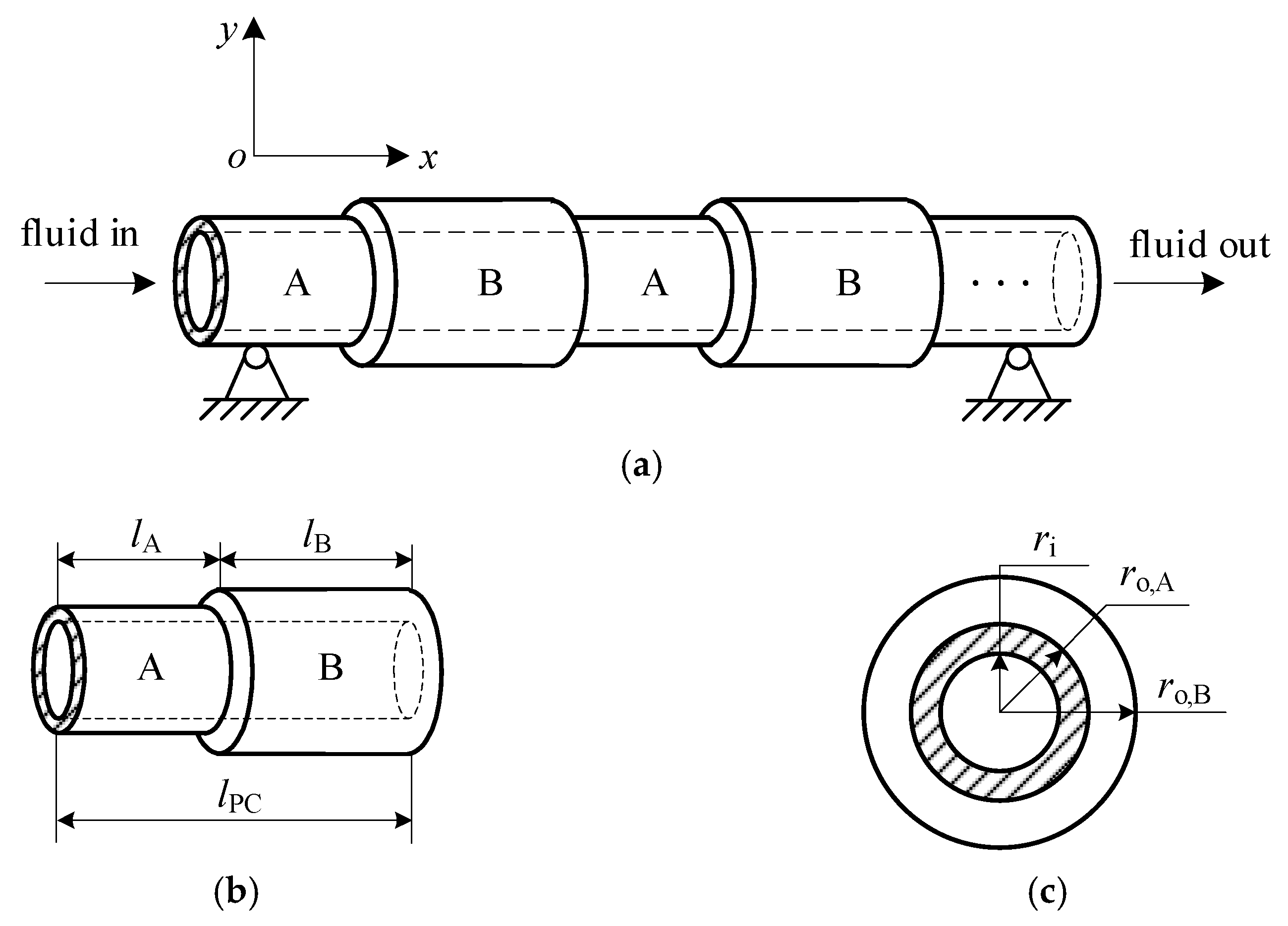
2. Mechanical Model and Dispersion Equation

The mechanical schematic of a fluid-conveying PC pipe with periodically varying cross-section is shown in Figure 1. The pipe is composed of n identical cells, and each cell consists of two segments with different geometrical cross-sections. The inner diameter is uniform along the pipe, while the outer diameter is different for the two segments. The lengths of pipe A and pipe B are lA and lB, respectively, and the lattice constant is lPC = lA + lB. ri,, ro,A, and ro,B are the uniform inner radius and outer radii of pipe A and pipe B, respectively. An inertial frame oxy is taken with the origin o at the left end of the pipe. The x and y axes coincide with the pipe axis and the direction of lateral deflection, respectively. Based on the Euler–Bernoulli beam model, and neglecting the gravity, imposed tension and pressurization effect, the relationship between the general force and displacement of the uniform pipe and fluid is derived as
{ M = E I θ x θ = w x E I 2 θ x 2 + Q = 0 Q x = m f ( t + U x ) 2 w + m p 2 w t 2
where E, I, mp and mf denote the Young’s modulus, moment inertia, mass per unit length of the pipe and fluid, respectively, and U the flow velocity. Q, M, w and θ are the shear force, bending moment, lateral deflection and slope of the pipe, respectively. The over dot and prime denote differentiations with respect to time t and the axial coordinate x, respectively. It should be noted that the sound velocity of the fluid is not considered in this study, since it is far higher compared to the flow velocity, which will lead to a trivial influence of the sound velocity on the FSI of the system. Such hypothesis will lose effectiveness when the flow velocity is increased close to the sound velocity of the fluid.
Eliminating θ from Equation (1), the well-known governing equation of fluid-conveying pipes can be obtained as
E I 4 w x 4 + ( m f + m p ) 2 w t 2 + 2 m f U 2 w x t + m f U 2 2 w x 2 = 0 .
Since the traveling wave generally exists in axially moving structures, herein, the harmonic solution with traveling wave form is first introduced as
w ( x ,   t ) = C e i ( ω t + k x ) ,
where C and ω (ω = 2πf) are the amplitude and angular frequency of the wave, respectively, k is the wavenumber and i the imaginary unit. Substitution of Equation (3) into Equation (2) leads to the dispersion equation as
E I k 4 m f U 2 k 2 2 m f U ω k ( m f + m p ) ω 2 = 0 .
For a given frequency ω, the wavenumber k can be generally solved as four roots from Equation (4): two real ones and a conjugate pair of imaginary ones, denoted by kn, n = 1, 2, 3, 4. The real wavenumbers indicate propagating waves, while the imaginary ones describe evanescent waves. Once k is determined from Equation (4), the deflection and slope of the pipe can be expanded as
{ w ( x ,   t ) = j = 1 4 C j e i ( ω t + k j x ) θ ( x ,   t ) = j = 1 4 i k j C j e i ( ω t + k j x )
Substituting Equation (5) into Equation (1), the shear force and bending moment can be further obtained as
{ Q ( x ,   t ) = E I j = 1 4 i k j 3 C j e i ( ω t + k j x ) M ( x ,   t ) = E I j = 1 4 k j 2 C j e i ( ω t + k j x )

3. Solution Procedure

3.1. Spectral Element Method

The SEM is a reliable semi-analytical approach, which has been proven quite efficient for the dynamical analysis of discontinuous systems. In this subsection, the SEM will be developed to treat the fluid-conveying pipes with periodically varying cross-section. Three steps will be taken in turn: (i) the dynamic stiffness matrix of a uniform pipe is derived; (ii) the local stiffness matrix for a single cell is determined; (iii) the global (spectral) stiffness matrix for the whole periodic pipe is obtained. The specific procedures are as follows:
First, for a fluid-conveying uniform pipe with length l, the deflection and slope of the two ends can be expressed as
w 1 = w ( 0 ,   t ) ,   θ 1 = θ ( 0 ,   t ) ,   w 2 = w ( l ,   t ) ,   θ 2 = θ ( l ,   t ) .
Substitution of Equation (5) into Equation (7) leads to the following matrix form of Equation (7)
U = e i ω t A C ,
where
U = [ w 1 θ 1 w 2 θ 2 ] T ,   C = [ C 1 C 2 C 3 C 4 ] T , A = [ 1 1 1 1 i k 1 i k 2 i k 3 i k 4 e i k 1 l e i k 2 l e i k 3 l e i k 4 l i k 1 e i k 1 l i k 2 e i k 2 l i k 3 e i k 3 l i k 4 e i k 4 l ] .
Similarly, the general force of the two ends can be expressed as
Q 1 = Q ( 0 ,   t ) ,   M 1 = M ( 0 ,   t ) ,   Q 2 = Q ( l ,   t ) ,   M 2 = M ( l ,   t ) .
Substituting Equation (6) into Equation (10), the matrix form of Equation (10) can be yielded as
F = e i ω t B C ,
where
F = [ Q 1 M 1 Q 2 M 2 ] T , B = E I [ i k 1 3 i k 2 3 i k 3 3 i k 4 3 k 1 2 k 2 2 k 3 2 k 4 2 i k 1 3 e i k 1 l i k 2 3 e i k 2 l i k 3 3 e i k 3 l i k 4 3 e i k 4 l k 1 2 e i k 1 l k 2 2 e i k 2 l k 3 2 e i k 3 l k 4 2 e i k 4 l ] .
Eliminating the coefficient matrix C from Equations (8) and (11), the relationship between the general force and displacement can be determined as
F = S U ,
where
S = B A 1
is defined as the dynamic stiffness matrix of a uniform pipe conveying fluid, which depends on the frequency, wavenumber, flow velocity, and physical and geometrical properties of the pipe and fluid.
Second, on the basis of Equation (14), the dynamic stiffness matrices corresponding to segments A and B with different geometrical properties can be respectively obtained as
{ S A = B A A A 1 S B = B B A B 1
where
A A = [ 1 1 1 1 i k 1 , A i k 2 , A i k 3 , A i k 4 , A e i k 1 , A l A e i k 2 , A l A e i k 3 , A l A e i k 4 , A l A i k 1 , A e i k 1 , A l A i k 2 , A e i k 2 , A l A i k 3 , A e i k 3 , A l A i k 4 , A e i k 4 , A l A ] , B A = E I A [ i k 1 , A 3 i k 2 , A 3 i k 3 , A 3 i k 4 , A 3 k 1 , A 2 k 2 , A 2 k 3 , A 2 k 4 , A 2 i k 1 , A 3 e i k 1 , A l A i k 2 , A 3 e i k 2 , A l A i k 3 , A 3 e i k 3 , A l A i k 4 , A 3 e i k 4 , A l A k 1 , A 2 e i k 1 , A l A k 2 , A 2 e i k 2 , A l A k 3 , A 2 e i k 3 , A l A k 4 , A 2 e i k 4 , A l A ] , A B = [ 1 1 1 1 i k 1 , B i k 2 , B i k 3 , B i k 4 , B e i k 1 , B l B e i k 2 , B l B e i k 3 , B l B e i k 4 , B l B i k 1 , B e i k 1 , B l B i k 2 , B e i k 2 , B l B i k 3 , B e i k 3 , B l B i k 4 , B e i k 4 , B l B ] , B B = E I B [ i k 1 , B 3 i k 2 , B 3 i k 3 , B 3 i k 4 , B 3 k 1 , B 2 k 2 , B 2 k 3 , B 2 k 4 , B 2 i k 1 , B 3 e i k 1 , B l B i k 2 , B 3 e i k 2 , B l B i k 3 , B 3 e i k 3 , B l B i k 4 , B 3 e i k 4 , B l B k 1 , B 2 e i k 1 , B l B k 2 , B 2 e i k 2 , B l B k 3 , B 2 e i k 3 , B l B k 4 , B 2 e i k 4 , B l B ] .
Considering the stiffness assembling procedure of traditional FEM, the relationship between the general force and displacement of a single cell can be written as
[ S LL S LM 0 S ML S MM S MR 0 S RM S RR ] { u L u M u R } = { f L 0 f R } ,
where uL and fL denote the displacement and loading force vectors at the left end of the cell, respectively, uR and fR those at the right end of the cell, respectively, uM the displacement vector at the joint of the two segments, and
u L = [ w 1 , A   θ 1 , A ] T ,   u R = [ w 2 , B   θ 2 , B ] T ,   u M = [ w M   θ M ] T , f L = [ Q 1 , A   M 1 , A ] T ,   f R = [ Q 2 , B   M 2 , B ] T , S LL = S A 1 ,   S LM = S A 2 ,   S M L = S A 3 ,   S MR = S B 2 , S RM = S B 3 ,   S RR = S B 4 ,   S MM = S A 4 + S B 1 , S A j = { [ S A ( j , 1 ) S A ( j , 2 ) S A ( j + 1 , 1 ) S A ( j + 1 , 2 ) ] ,   j = 1 ,   3 [ S A ( j 1 , 3 ) S A ( j 1 , 4 ) S A ( j , 3 ) S A ( j , 4 ) ] ,   j = 2 ,   4 S B j = { [ S B ( j , 1 ) S B ( j , 2 ) S B ( j + 1 , 1 ) S B ( j + 1 , 2 ) ] ,   j = 1 ,   3 [ S B ( j 1 , 3 ) S B ( j 1 , 4 ) S B ( j , 3 ) S B ( j , 4 ) ] ,   j = 2 ,   4
[ ](j, k) represents the element at the jth row and kth column of the matrix [ ]. Further, since the displacement at the joint of the two segments is not necessary to be determined, one can eliminate uM from Equation (17), and Equation (17) is then simplified to
[ S 1 S 2 S 3 S 4 ] [ u L u R ] = [ f L f R ] ,
where
S 1 = S LL S LM S MM 1 S ML ,   S 2 = S LM S MM 1 S MR , S 3 = S RM S MM 1 S ML ,   S 4 = S RR S RM S MM 1 S MR .
Thus, the local stiffness matrix for a single cell is yielded as
S 1 = [ S 1 S 2 S 3 S 4 ] ,
which is a 4 × 4 matrix. Based on S1 and Bloch’s theorem of plane wave propagation in phononic crystals, we can obtain
u R = e i q l PC u L ,   f R = e i q l PC f L ,
where q is the Bloch wave vector. In general, the real and imaginary parts of q represent, respectively, the phase difference and amplitude decay rate of wave motion between two adjacent cells in a PC structure. Substituting Equation (22) into Equation (19), the following linear equations are yielded
( S 3 + S 41   e i q l PC + S 2   e 2 i q l PC ) u L = 0 .
If Equation (23) has a nontrivial solution, the determinant of the coefficient matrix must be vanished, that is,
det ( S 3 + S 41   e i q l PC + S 2   e 2 i q l PC ) = 0 .
Hence, the relationship between the incident frequency and wave vector can be determined by Equation (24) once the other system parameters are provided. Further, with scanning the frequency, if the imaginary part of q is vanished, the incident wave can propagate freely, which indicates a pass band; if the imaginary part of q is present, the incident wave will be attenuated along the pipe, with absorption of the vibration energy by the PC structure, which indicates a stop band, i.e., a BG. The BG regions of the present periodic pipe can thus be measured.
Finally, for the whole periodic pipe with n cells, the stiffness assembling procedure used above is also adopted, and the spectral stiffness matrix for such composite structure is ultimately achieved as
S n = [ S 1 S 2 0 0 S 3 S 4 + S 1 S 2 0 0 S 3 S 4 + S 1 0 0 S 2 0 0 S 3 S 4 + S 1 S 2 0 0 S 3 S 4 ] ,
which is a (2n + 2) × (2n + 2) matrix. The relationship between the general force and displacement at both ends of all cells along the whole pipe can then be obtained as
[ Q L M L Q R M R ] T = S n · [ w L θ L w R θ R ] T .
Using Equation (26), for an arbitrary incident wave, the edge displacement of each cell, namely, the node displacement, can be calculated, and consequently the frequency response and vibration shape can be attained.
In addition, based on Equation (26), the natural frequency and vibration mode of the periodic pipe can be determined. Since these properties are associated with the end condition, we first give the general displacement and force at the left and right ends of the pinned-pinned pipe and those at both ends of all cells as
w L = w R = 0 ,   θ L 0 ,   θ R 0 ,   others 0 , Q L 0 ,   Q R 0 ,   M L = M R = 0 ,   other   loads = 0 .
Thus, Equation (26) can be written as
[ Q L 0 Q R 0 ] T = S n · [ 0 θ L 0 θ R ] T .
A nontrivial solution of Equation (28) requires a simplified determinant of the coefficient matrix equal to zero, which yields the characteristic equation of the system as
det ( S n , s ) = 0 ,
where
S n , s = [ S 1 ( 2 , 2 ) S 2 ( 2 , 1 ) S 2 ( 2 , 2 ) 0 0 S 3 ( 1 , 2 ) S 41 ( 1 , 1 ) S 41 ( 1 , 2 ) 0 S 3 ( 2 , 2 ) S 41 ( 2 , 1 ) S 41 ( 2 , 2 ) 0 0 0 0 0 0 S 41 ( 1 , 1 ) S 41 ( 1 , 2 ) S 2 ( 1 , 2 ) 0 S 41 ( 2 , 1 ) S 41 ( 2 , 2 ) S 2 ( 2 , 2 ) 0 0 S 3 ( 2 , 1 ) S 3 ( 2 , 2 ) S 4 ( 2 , 2 ) ] ,
and S41 = S4 + S1. The natural frequency can then be determined by Equation (29), and the mode shape can be simulated in terms of the node displacements obtained by Equation (28).

3.2. Transfer Matrix Method

The TMM is one of the most commonly used methods to deal with discontinuous dynamical systems, owing to its simplicity and accuracy in calculation. Herein, the TMM is also employed to calculate the BG regions, and the results are further compared with those by the SEM.
According to the continuity between the nth and (n + 1)th cells, and that between segment A and segment B in the (n + 1)th cell of the periodic pipe, their deflection, slope, bending moment and shear force at the interfaces are equal, respectively, that is
[ w θ M Q ] n + 1 , A T | ( 0 , t ) = [ w θ M Q ] n , B T | ( l PC , t ) , [ w θ M Q ] n + 1 , A T | ( l A , t ) = [ w θ M Q ] n + 1 , B T | ( l A , t ) .
Based on Equation (31), the amplitude relationship between adjacent cells can be described by the transfer matrix T, and consequently that between the first and nth cells can be determined by Tn−1, by which the frequency response and vibration shape can be obtained.
In order to calculate the BG region, Bloch’s theorem is applied again, leading to the following eigenvalue problem
det ( T e i q l PC   I ) = 0 ,
where I is the identity matrix. Thus, the relationship between the incident frequency and wave vector can be determined.
In terms of the above derivations, it is found that although in the SEM, the matrix Sn shown in Equation (25) becomes complicated when the number of substructures gets high, the calculation and time consumed will be generally acceptable since it is essentially a large sparse matrix with most zero elements, which is a quasi-diagonal matrix. Actually, compared with other traditional methods, the SEM has superior characteristics. It is readily seen that by using the SEM, not only the BG characteristics but also the natural frequency and vibration mode of the PC pipe conveying fluid can be achieved. However, some other methods, e.g., the homogenization method and Galerkin method, can hardly solve the BG of such PC structures, while the TMM is difficult to treat the natural frequency and mode shape though the BG can be obtained.

4. Results and Discussion

In this section, numerical examples will be employed to display the BG characteristics and free vibration behaviors of the fluid-conveying pipes with periodically varying cross-section. The physical and geometrical parameter values used are taken as: the material of the pipe is epoxy with Ep = 4.35 GPa and ρp = 1180 kg/m3; the inner radius of the pipe is ri = 0.045 m, outer ones are ro,A = 0.05 m and ro,B = 0.07 m, respectively, and the fluid is water with ρf = 103 kg/m3 and U = 20 m/s, if not specified. Comprehensive parametric studies will be conducted to provide reference for practical engineering design.

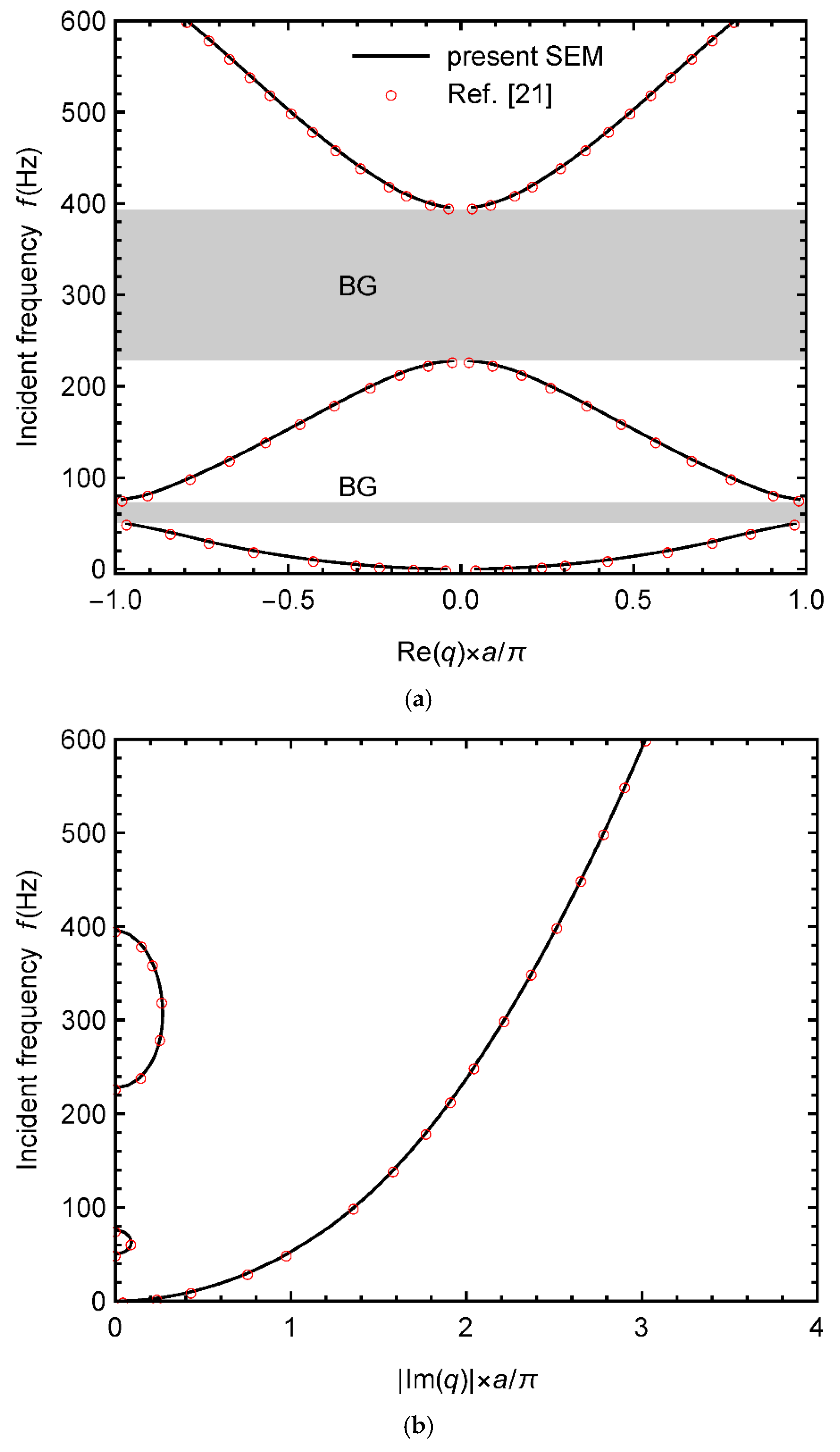
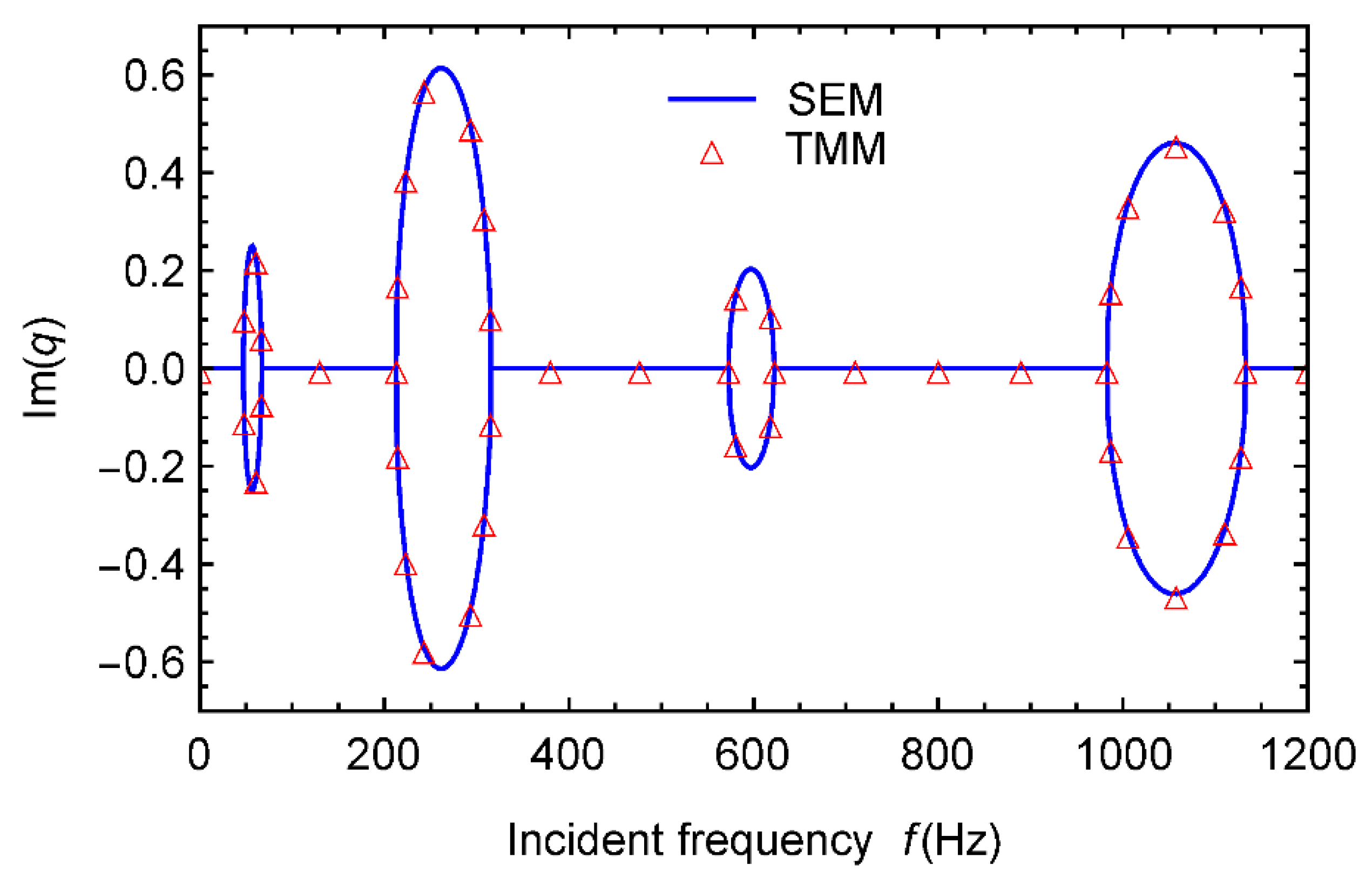
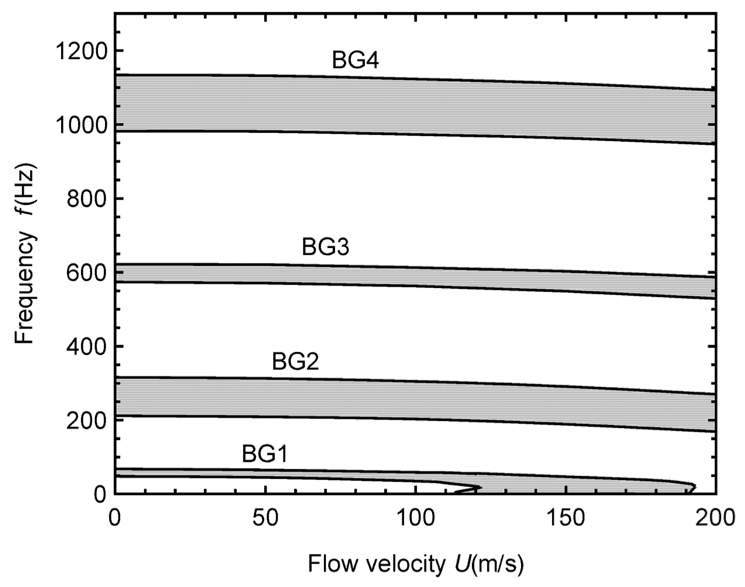
4.1. BG of an Infinite Pipe

In this part, the substructure length is taken as lA = lB = 0.5 m and the lattice constant is lPC = 1 m, if not specified. In order to validate the accuracy of SEM in calculating the periodic pipe, a literature comparison is first carried out for the band structure, as shown in Figure 2, in which the grey regions indicate the BG regions of the system. It is noted that due to lack of available research on a fluid-conveying pipe with periodically varying cross-section, the SEM herein is applied in a static-water-filled periodic pipe composed of different materials, and the results obtained are compared with those in Ref. [21] by the TMM under the same parameter values (for the specific parameter values employed, see the literature). It can be seen that the two results are in good agreement, indicating the accuracy of the present SE procedure. Moreover, it is observed that under the specified range of the incident frequency, there exist two BG regions: 50 Hz~76 Hz, 228 Hz~396 Hz, and the higher region is broader.
Figure 3 depicts the imaginary part of the wave vector as function of the incident frequency for the present fluid-conveying pipe with periodically varying cross-section by the SEM and TMM. Actually, Figure 2 has indicated the fact that the BG of the pipe can be determined by the existence of the imaginary part of q. In Figure 3 and what follows, therefore, the BG regions will be measured directly by this rule. It can be seen in Figure 3 that the results of SEM and TMM are in good agreement, showing that the two methods are both effective in calculating the band structure of the periodic pipe conveying fluid. In addition, under the specified range of the incident frequency, there exist four BG regions: 47 Hz~67 Hz, 213 Hz~315 Hz, 573 Hz~623 Hz, 983 Hz~1133 Hz. The lowest BG region is the narrowest, and the highest BG is the broadest.
Figure 4 illustrates the effect of the ratio of substructure outer radius on the BG of the present periodic pipe. It is clear that not any BG is present when the two segments hold the same outer radius, and it occurs only in the case of difference in radius. This demonstrates that the geometrical difference in cross-section of the two segments is the essence causing BG. In addition, it is found that the lowest BG region, BG1, is the narrowest one. With increasing the ratio, BG1 has little change, BG2 and BG3 get broader greatly, while the highest BG region, BG4, gets broader first, and then becomes narrower until vanished, showing that it is not always a monotonic evolution of BG with the ratio of substructure outer radius. Moreover, the regions of BG1, BG2 and BG4 start around the ratio ro,B/ro,A = 1.05, while that of BG3 starts around ro,B/ro,A = 1.3.
Figure 5 displays the effect of the ratio of substructure length on the BG. A complicated impact of the substructure lengths can be immediately found. It is observed that with increasing the ratio, the BG regions basically move to higher frequencies, especially for higher BGs. However, the evolution of each BG region with the ratio is different. Within the specified range of the ratio, with increasing lB/lA, BG1 becomes a little broader, BG2 experiences an evolution of ‘broader–narrower‘, BG3 ‘broader–narrower–broader‘ and BG4 ‘broader–narrower–broader–narrower–broader‘. BG4 holds the leading variation. Some peculiar points of ratio resulting in local contraction of the BG region are present in BG3 and BG4.
It is noted that according to the reports of most related literatures, the excitation frequency acting on the present slender pipes conveying fluid is usually below 1200 Hz. In addition, it can be seen in Figure 4 and Figure 5 that under the considered pipe period, the representative BG evolutions have been fully displayed, and the designed stepped pipe can also be readily fulfilled in fabrication. Therefore, the model proposed is practicable.
The FSI effect on the BG is further discussed in Figure 6. It is noted that the impact of flow velocity is analyzed herein since it is the chief parameter reflecting the FSI effect of fluid-conveying structures. It is observed that the location and width of the BG regions are hardly changed at lower flow velocities, and only higher flow velocities can lead to evident movement of the BG regions, revealing that the FSI has significant effect on the BG only at higher flow velocities. In addition, the region of BG1 has a special evolution. When the flow velocity is ranged over 113 m/s~122 m/s, BG1 exhibits divergence. If the flow velocity continues increasing from 122 m/s, BG1 will cover the frequency range from 0, and the pipe presents a complete ultra-low frequency BG. Thanks to the presence of such complete ultra-low frequency BG in the PC pipe conveying fluid, the incident waves with frequency of 0~50 Hz cannot propagate along the slender pipe, meaning the vibration within this frequency range will be effectively suppressed. This performance of the system will facilitate to expand the application of PC pipes conveying fluid in ultra-low frequency conditions. However, such characteristic will vanish when the flow velocity exceeds 193 m/s.
In order to validate the vibration suppression effect of the periodic pipe, the frequency response and vibration attenuation shape of a finite pipe are further presented in terms of Equation (26). Applying a periodic excitation of ML = 1eiωtN∙m (others = 0) at the left end of the pipe, we can obtain the logarithmic relationship between the amplitude of the right end and the incident frequency, as shown in Figure 7, in which the periodic pipes with 4, 7 and 10 cells, as an example, are calculated for comparison. It is clear that within the specified frequency range, there are four BG regions, which just correspond to those in Figure 3. Under the parameter values used, the vibration is attenuated better in BG2 and BG4. With increasing the number of cells, the frequency ranges of BGs of various pipes are almost constant, indicating that the BGs of the periodic pipes are independent of the number of cells, while the vibration attenuation is getting greater. This is just the contribution of periodicity of the structure.
By exerting the above excitation and selecting different excitation frequencies inside and outside the first two BG regions as examples, the response shapes of a representative pipe with 7 cells are illustrated in Figure 8. Obviously, the vibration of the pipe has been highly suppressed by the periodic structure when the incident frequency falls in the BG regions. There is hardly any vibration occurring for the frequency in BG2. Even in BG1, as shown in Figure 8a, there is still some response present near the left end of the pipe, it is not able to transmit along the pipe. This confirms the vibration suppression effect of the present periodic pipe conveying fluid. Moreover, the attenuation shapes of the pipe without fluid loading are also shown in the figure for comparison. A significant effect of FSI can be observed.

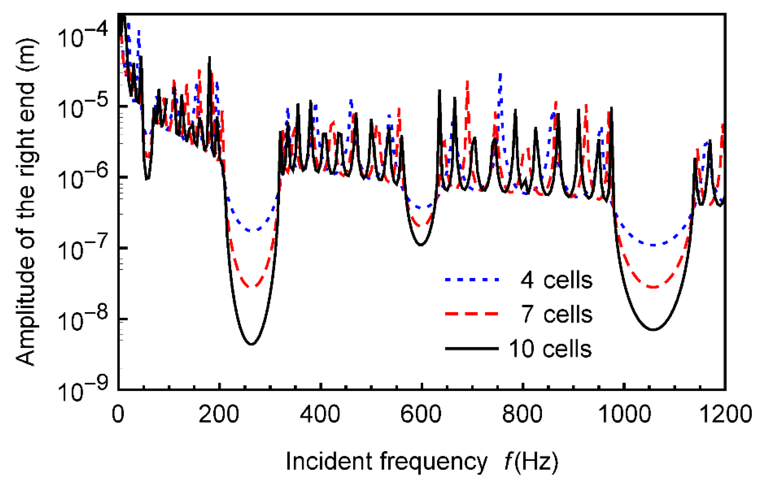
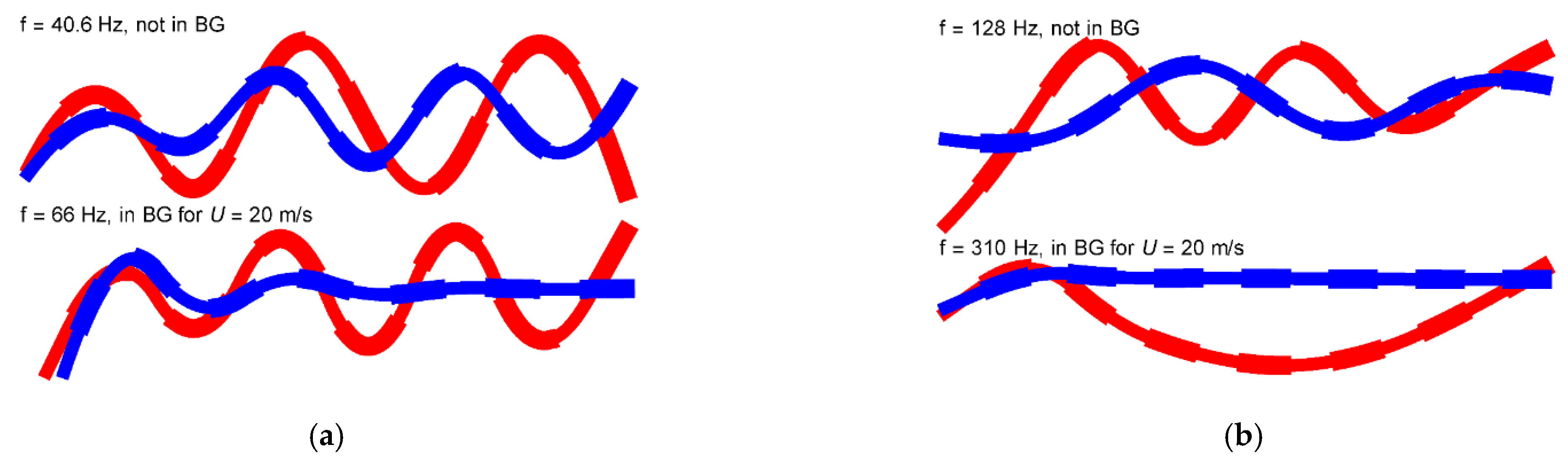
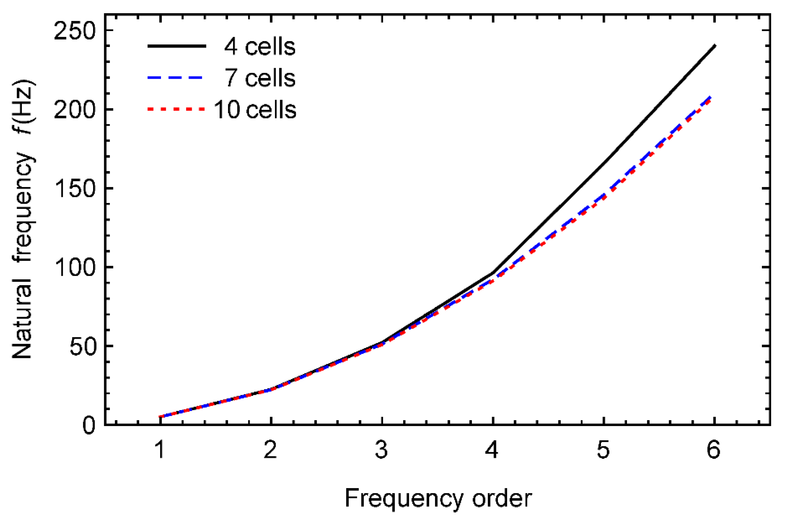
4.2. Free Vibration of Finite Pipe

In this part, the free vibration properties, including the natural frequency and mode shape, of the fluid-conveying pipes with periodically varying cross-section will be examined by using Equations (28) and (29). The substructure length is taken as lA = lB, and despite the number of cells, the total length of the pipe is fixed to 3 m in order to examine the effect of number of cells on the natural properties of the present periodic pipe conveying fluid under the same pipe length.
Figure 9 presents the first six natural frequencies of the pipe for different numbers of cells. Corresponding to the foregoing study, the periodic models with 4, 7, and 10 cells are also employed for analysis. It can be seen that under the same total length, with increasing the number of cells, the natural frequencies of the pipe are decreased, meaning the rigidity is reduced, and this is obvious especially for higher frequencies. Furthermore, this performance is also obvious for smaller numbers of cells. For the pipes with larger numbers of cells, the natural frequencies almost remain constant.
Corresponding to the natural frequencies in Figure 9 and Figure 10 exhibits the first six mode shapes of free vibration for the pipe. To be comparable, the curves in each single subgraph have been plotted in the same dimension of coordinate system, although the dimensions of some subgraphs have been modified for observation. Moreover, it should be noted that the present mode shapes are basically asymptotic since they are quite sensitive to the corresponding natural frequencies, and due to lack of adequate nodes, only the first three modes of the pipe with 4 cells can be plotted. The modes without fluid loading are also displayed. It can be seen that the effect of FSI is evident.
To further discuss the effects of FSI and the number of cells on the free vibration of the periodic pipe, Figure 11 displays the evolution of natural frequencies with the flow velocity for different numbers of cells. It is clear that due to the influence of FSI, the first four natural frequencies of the pipes with 4 and 10 cells all demonstrate a decreasing trend with the increase of flow velocity. When the critical flow velocity is reached, at which the first natural frequency vanishes, the static instability occurs and the pipe is subject to buckling. Lower natural frequencies and critical flow velocity of the periodic pipe with 4 and 10 cells are very close, while higher ones will present difference. The third and fourth natural frequencies of the pipe with 10 cells are first lower than those of the pipe with 4 cells, and will become higher than the pipe with 4 cells when the flow velocity is increased to higher values, especially for the fourth natural frequency. This implies that the FSI has a greater effect on the pipes with smaller numbers of cells.
In addition, it is worth noting in Figure 11 that when the flow velocity exceeds the critical value, it is necessary to consider other natural frequencies since if the flow velocity continues increasing up to a certain value, the first natural frequency will be present again, and gradually coincide with the second natural frequency, leading to a ‘mode-coalescence flutter’ of the pipe. With increasing the flow velocity, such ‘mode-coalescence flutter’ will occur involving the third and higher frequencies. Therefore, it is still of significance to study higher frequencies even beyond the critical flow velocity.

5. Conclusions

This paper explores the BG characteristics and free vibration behaviors of fluid-conveying PC pipes with periodically varying cross-section. The dispersion relationship is obtained based on the traveling wave property, and treated by the SEM. The TMM is also introduced to confirm the SEM. The BG distribution and frequency response of the periodic pipe are achieved, and the natural frequency and mode shape are also attained. Major parametric studies are carried out. Some significant conclusions are drawn as follows:
(i)
The BG of the periodic structures can be determined directly by the existence of the imaginary part of wave vector. The SEM can be used for a comprehensive analysis of the BG region, frequency response, natural frequency and vibration mode of the PC structures, while the TMM is just effective in studying the BG characteristics.
(ii)
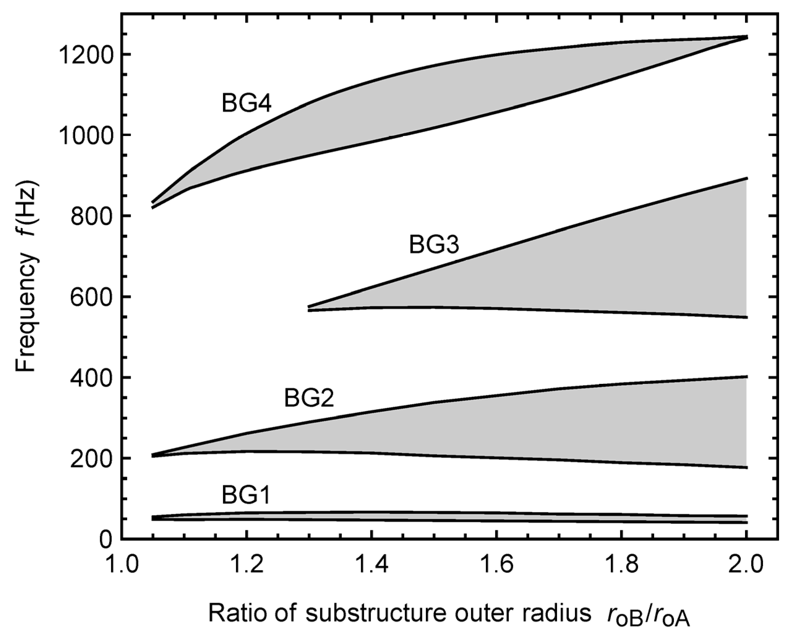
The geometrical difference of the substructure outer diameter is the essential reason causing BGs. The ratios of substructure outer diameter and length both have significant effects on the BG distribution of the present periodic pipe, while the influence of FSI is obvious only at higher flow velocities. The BG distribution of the pipe is independent of the number of cells, while the vibration suppression effect is getting greater as the number of cells is increased.
(iii)
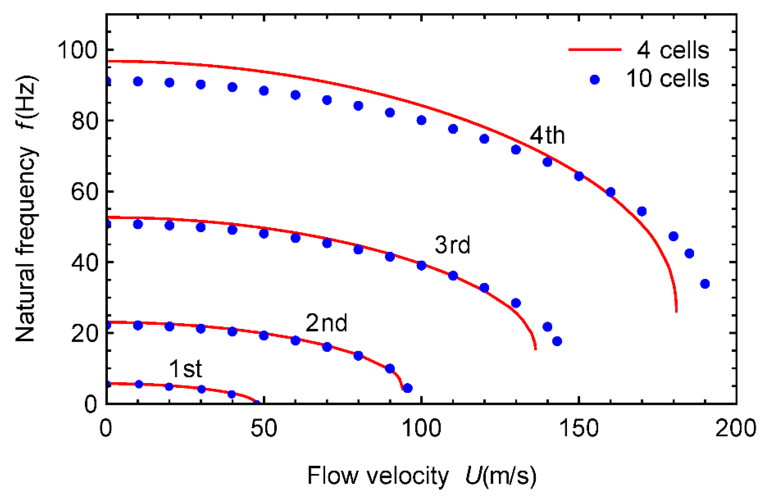
The number of cells has an obvious effect on higher order natural frequencies of the periodic pipe, while has an irregular impact on the mode shapes. The effect of FSI is greater for the pipes with smaller numbers of cells.
Additionally, it should be discussed on the targeted applications of the BGs in different frequency range for the fluid-conveying pipe systems. Actually, these BGs can be designed to deal with various vibration resources. Lower frequency BGs are mainly used to reduce resonances induced by vehicle- and human-type loads; medium frequency BGs are used to treat wind- and seism-type loads; higher frequency BGs are used to eliminate noise. Consequently, attaining multiple broadband BGs is an essential aim of developing such PC dynamical structures.
Granted, according to the traditional designs, the vibration suppression can be realized by using fixtures and dampers. However, under some special circumstance where adding external structures is not allowed, how to reduce the pipe vibration becomes a topic today. Motivated by the PC idea, this paper actually provides a novel technical approach to effectively suppress the vibration transmission just by modifying the geometrical construction of the pipe itself, namely vibration self-suppression. Such design is of better significance for the development of PC theories and potential engineering applications.

Author Contributions

Conceptualization, H.Y. and F.L.; Investigation, J.G.; Methodology, Y.Q.; Software, Y.C.; Validation, A.G.; Writing—original draft preparation, F.L.; Writing—review & editing, H.Y. and F.L. All authors have read and agreed to the published version of the manuscript.

Funding

This research was funded by the National Natural Science Foundation of China under Grant No. 12072311 and 11972050 and High-Level Talents Program of Yangzhou University.

Conflicts of Interest

The authors declare that they have no conflict of interest.

References

  1. Païdoussis, M.P. Fluid-Structure Interactions: Slender Structures and Axial Flow, 2nd ed.; Academic Press: London, UK, 2014. [Google Scholar]
  2. Tan, X.; Ding, H.; Sun, J.-Q.; Chen, L.-Q. Primary and super-harmonic resonances of Timoshenko pipes conveying high-speed fluid. Ocean Eng. 2020, 203, 107258. [Google Scholar] [CrossRef]
  3. Tan, X.; Ding, H. Parametric resonances of Timoshenko pipes conveying pulsating high-speed fluids. J. Sound Vib. 2020, 485, 115594. [Google Scholar] [CrossRef]
  4. Silverberg, J.L.; Evans, A.A.; McLeod, L.; Hayward, R.C.; Hull, T.; Santangelo, C.D.; Cohen, I. Using origami design principles to fold reprogrammable mechanical metamaterials. Science 2014, 345, 647–650. [Google Scholar] [CrossRef] [PubMed]
  5. Yang, X.-D.; Cui, Q.-D.; Qian, Y.-J.; Zhang, W.; Lim, C.W. Modulating band gap structure by parametric excitations. J. Appl. Mech. 2018, 85, 061012. [Google Scholar] [CrossRef]
  6. Yang, X.-D.; Cui, Q.-D.; Zhang, W. Wave manipulation of two-dimensional periodic lattice by parametric excitation. J. Appl. Mech. 2019, 87, 1–17. [Google Scholar] [CrossRef]
  7. Salari-Sharif, L.; Haghpanah, B.; Izard, A.G.; Tootkaboni, M.; Valdevit, L. Negative-stiffness inclusions as a platform for real-time tunable phononic metamaterials. Phys. Rev. Appl. 2019, 11, 024062. [Google Scholar] [CrossRef] [Green Version]
  8. Qian, Y.-J.; Cui, Q.-D.; Yang, X.-D.; Zhang, W. Manipulating transverse waves through 1D metamaterial by longitudinal vibrations. Int. J. Mech. Sci. 2020, 168, 105296. [Google Scholar] [CrossRef]
  9. Miao, L.; Li, C.; Lei, L.; Fang, H.; Liang, X. A new periodic structure composite material with quasi-phononic crystals. Phys. Lett. A 2020, 384, 126594. [Google Scholar] [CrossRef]
  10. Panahi, E.; Hosseinkhani, A.; Khansanami, M.F.; Younesian, D.; Ranjbar, M. Novel cross shape phononic crystals with broadband vibration wave attenuation characteristic: Design, modeling and testing. Thin-Walled Struct. 2021, 163, 107665. [Google Scholar] [CrossRef]
  11. Plisson, J.; Pelat, A.; Gautier, F.; Garcia, V.R.; Bourdon, T. Experimental evidence of absolute bandgaps in phononic crystal pipes. Appl. Phys. Lett. 2020, 116, 201902. [Google Scholar] [CrossRef]
  12. Lyu, X.; Ding, Q.; Yang, T. Merging phononic crystals and acoustic black holes. Appl. Math. Mech. 2020, 41, 279–288. [Google Scholar] [CrossRef]
  13. Tang, L.; Cheng, L.; Chen, K. Complete sub-wavelength flexural wave band gaps in plates with periodic acoustic black holes. J. Sound Vib. 2021, 502, 116102. [Google Scholar] [CrossRef]
  14. Li, H.; Ding, Q.; Ma, Z.; Ren, Q.; Lyu, X.; Qin, Z.-H.; Wei, L.; Żur, K.K.; Yang, T. Breaking reciprocity and preserving-frequency using linear acoustic metamaterials. Int. J. Mod. Phys. B 2021, 35, 2150089. [Google Scholar] [CrossRef]
  15. He, M.-X.; Ding, Q. Data-driven optimization of the periodic beam with multiple acoustic black holes. J. Sound Vib. 2021, 493, 115816. [Google Scholar] [CrossRef]
  16. Lucklum, R.; Zubtsov, M.; Pennec, Y. Tubular bell—New class of (Bio)chemical microsensors. Procedia Eng. 2015, 120, 520–523. [Google Scholar] [CrossRef] [Green Version]
  17. Gueddida, A.; Pennec, Y.; Zhang, V.; Lucklum, F.; Vellekoop, M.; Mukhin, N.; Bonello, B.; Rouhani, B.D. Tubular phononic crystal sensor. J. Appl. Phys. 2021, 130, 105103. [Google Scholar] [CrossRef]
  18. Mukhin, N.; Lucklum, R. Periodic tubular structures and phononic crystals towards High-Q liquid ultrasonic inline sensors for pipes. Sensors 2021, 21, 5982. [Google Scholar] [CrossRef]
  19. Koo, G.; Park, Y. Vibration reduction by using periodic supports in a piping system. J. Sound Vib. 1998, 210, 53–68. [Google Scholar] [CrossRef]
  20. Dai, H.; Wang, L.; Ni, Q. Dynamics of a fluid-conveying pipe composed of two different materials. Int. J. Eng. Sci. 2013, 73, 67–76. [Google Scholar] [CrossRef]
  21. Yu, D.; Wen, J.; Zhao, H.; Liu, Y.; Wen, X. Vibration reduction by using the idea of phononic crystals in a pipe-conveying fluid. J. Sound Vib. 2008, 318, 193–205. [Google Scholar] [CrossRef]
  22. Yu, D.; Wen, J.; Zhao, H.; Liu, Y.; Wen, X. Flexural vibration band gap in a periodic fluid-conveying pipe system based on the Timoshenko beam theory. J. Vib. Acoust. 2011, 133, 014502. [Google Scholar] [CrossRef]
  23. Yu, D.L.; Païdoussis, M.P.; Shen, H.J.; Wang, L. Dynamic stability of periodic pipes conveying fluid. ASME J. Appl. Mech. 2014, 81, 011008. [Google Scholar] [CrossRef]
  24. Yu, D.-L.; Shen, H.-J.; Liu, J.-W.; Yin, J.-F.; Zhang, Z.-F.; Wen, J.-H. Propagation of acoustic waves in a fluid-filled pipe with periodic elastic Helmholtz resonators. Chin. Phys. B 2018, 27, 064301. [Google Scholar] [CrossRef]
  25. Wen, J.H.; Shen, H.J.; Yu, D.L.; Wen, X.S. Theoretical and experimental investigation of flexural wave propagating in a periodic pipe with fluid-filled loading. Chin. Phys. Lett. 2010, 27, 114301. [Google Scholar]
  26. Wei, Z.-D.; Li, B.-R.; Du, J.-M.; Yang, G. Theoretical and experimental investigation of flexural vibration transfer properties of high-pressure periodic pipe. Chin. Phys. Lett. 2016, 33, 044303. [Google Scholar] [CrossRef]
  27. Shen, H.; Wen, J.; Yu, D.; Yuan, B.; Wen, X. Stability of fluid-conveying periodic shells on an elastic foundation with external loads. J. Fluids Struct. 2014, 46, 134–148. [Google Scholar] [CrossRef]
  28. Shen, H.; Wen, J.; Yu, D.; Asgari, M.; Wen, X. Control of sound and vibration of fluid-filled cylindrical shells via periodic design and active control. J. Sound Vib. 2013, 332, 4193–4209. [Google Scholar] [CrossRef]
  29. Shen, H.; Wen, J.; Yu, D.; Wen, X. Stability of clamped-clamped periodic functionally graded material shells conveying fluid. J. Vib. Control. 2014, 21, 3034–3046. [Google Scholar] [CrossRef]
  30. Hu, B.; Zhu, F.-L.; Yu, D.-L.; Liu, J.-W.; Zhang, Z.-F.; Zhong, J.; Wen, J.-H. Impact vibration properties of locally resonant fluid-conveying pipes*. Chin. Phys. B 2020, 29, 124301. [Google Scholar] [CrossRef]
  31. Hu, B.; Zhang, Z.; Yu, D.; Liu, J.; Zhu, F. Broadband bandgap and shock vibration properties of acoustic metamaterial fluid-filled pipes. J. Appl. Phys. 2020, 128, 205103. [Google Scholar] [CrossRef]
  32. Liang, F.; Yang, X.-D. Wave properties and band gap analysis of deploying pipes conveying fluid with periodic varying parameters. Appl. Math. Model. 2020, 77, 522–538. [Google Scholar] [CrossRef]
  33. Poggetto, V.F.D.; Serpa, A.L. Flexural wave band gaps in a ternary periodic metamaterial plate using the plane wave expansion method. J. Sound Vib. 2021, 495, 115909. [Google Scholar] [CrossRef]
  34. Wu, L.-Y.; Wu, M.-L.; Chen, L.-W. The narrow pass band filter of tunable 1D phononic crystals with a dielectric elastomer layer. Smart Mater. Struct. 2008, 18, 015011. [Google Scholar] [CrossRef]
  35. Xiao, Y.; Wen, J. Closed-form formulas for bandgap estimation and design of metastructures undergoing longitudinal or torsional vibration. J. Sound Vib. 2020, 485, 115578. [Google Scholar] [CrossRef]
  36. Xiao, Y.; Wang, S.; Li, Y.; Wen, J. Closed-form bandgap design formulas for beam-type metastructures. Mech. Syst. Signal Process. 2021, 159, 107777. [Google Scholar] [CrossRef]
  37. Sun, H.; Du, X.; Pai, P. Theory of metamaterial beams for broadband vibration absorption. J. Intell. Mater. Syst. Struct. 2010, 21, 1085–1101. [Google Scholar] [CrossRef]
  38. Wang, T.; Sheng, M.-P.; Qin, Q. Multi-flexural band gaps in an Euler–Bernoulli beam with lateral local resonators. Phys. Lett. A 2016, 380, 525–529. [Google Scholar] [CrossRef]
  39. Alsaffar, Y.; Sassi, S.; Baz, A. Band gap characteristics of periodic gyroscopic systems. J. Sound Vib. 2018, 435, 301–322. [Google Scholar] [CrossRef]
  40. Lee, U.; Kim, D.; Park, I. Dynamic modeling and analysis of the PZT-bonded composite Timoshenko beams: Spectral element method. J. Sound Vib. 2013, 332, 1585–1609. [Google Scholar] [CrossRef]
  41. Park, I.; Lee, U. Dynamic analysis of smart composite beams by using the frequency-domain spectral element method. J. Mech. Sci. Technol. 2012, 26, 2511–2521. [Google Scholar] [CrossRef]
  42. Lee, U.; Park, J. Spectral element modelling and analysis of a pipeline conveying internal unsteady fluid. J. Fluids Struct. 2005, 22, 273–292. [Google Scholar] [CrossRef]
  43. Lee, U.; Kim, J.; Leung, A.Y.T. The spectral element method in structural dynamics. Shock. Vib. Dig. 2000, 32, 451–465. [Google Scholar] [CrossRef]
  44. Xiao, Y.; Wen, J.; Yu, D.; Wen, X. Flexural wave propagation in beams with periodically attached vibration absorbers: Band-gap behavior and band formation mechanisms. J. Sound Vib. 2013, 332, 867–893. [Google Scholar] [CrossRef]
  45. Zuo, S.-L.; Li, F.-M.; Zhang, C. Numerical and experimental investigations on the vibration band-gap properties of periodic rigid frame structures. Acta Mech. 2016, 227, 1653–1669. [Google Scholar] [CrossRef]
  46. Fabro, A.T.; Beli, D.; Ferguson, N.S.; Arruda, J.R.F.; Mace, B.R. Wave and vibration analysis of elastic metamaterial and phononic crystal beams with slowly varying properties. Wave Motion 2021, 103, 102728. [Google Scholar] [CrossRef]
  47. Pereira, F.N.; Dos Santos, J. Phononic crystal investigation using a fluid-structure circular cylindrical shell spectral element. Mech. Syst. Signal Process. 2021, 148, 107100. [Google Scholar] [CrossRef]
Figure 1. Mechanical model of a fluid-conveying PC pipe with periodically varying cross-section: (a) model with n cells, (b) a single cell, (c) cross-section of the pipe.
Applsci 11 10485 g001
Figure 2. Band structure of a static-water-filled periodic pipe: (a) real part of the wave vector, (b) absolute imaginary part of the wave vector.
Applsci 11 10485 g002
Figure 3. Imaginary part of the present fluid-conveying pipe with periodically varying cross-section.
Applsci 11 10485 g003
Figure 4. BGs as function of the ratio of substructure outer radius.
Applsci 11 10485 g004
Figure 5. BGs as function of the ratio of substructure length.
Applsci 11 10485 g005
Figure 6. BGs as function of the flow velocity.
Applsci 11 10485 g006
Figure 7. Frequency responses of the fluid-conveying periodic pipe with different numbers of cells.
Applsci 11 10485 g007
Figure 8. Vibration attenuation shapes of a representative fluid-conveying periodic pipe with 7 cells in different BG regions: (a) BG1, (b) BG2. (the thick and thin curves denote the two segments of a cell.) Blue—U = 20 m/s, Red—without fluid loading.
Applsci 11 10485 g008
Figure 9. Natural frequencies of the fluid-conveying periodic pipe with different numbers of cells.
Applsci 11 10485 g009
Figure 10. Mode shapes of the fluid-conveying periodic pipe with different numbers of cells: (a) Mode 1, (b) Mode 2, (c) Mode 3, (d) Mode 4, (e) Mode 5, (f) Mode 6. Blue—U = 20 m/s, Red—without fluid loading.
Applsci 11 10485 g010
Figure 11. Natural frequencies of the fluid-conveying periodic pipe as function of the flow velocity for different numbers of cells.
Applsci 11 10485 g011
Publisher’s Note: MDPI stays neutral with regard to jurisdictional claims in published maps and institutional affiliations.

