
Biomechanical Evaluation of the Lumbar Spine by Using a New Interspinous Process Device: A Finite Element Analysis


Abstract
:1. Introduction
2. Materials and Methods
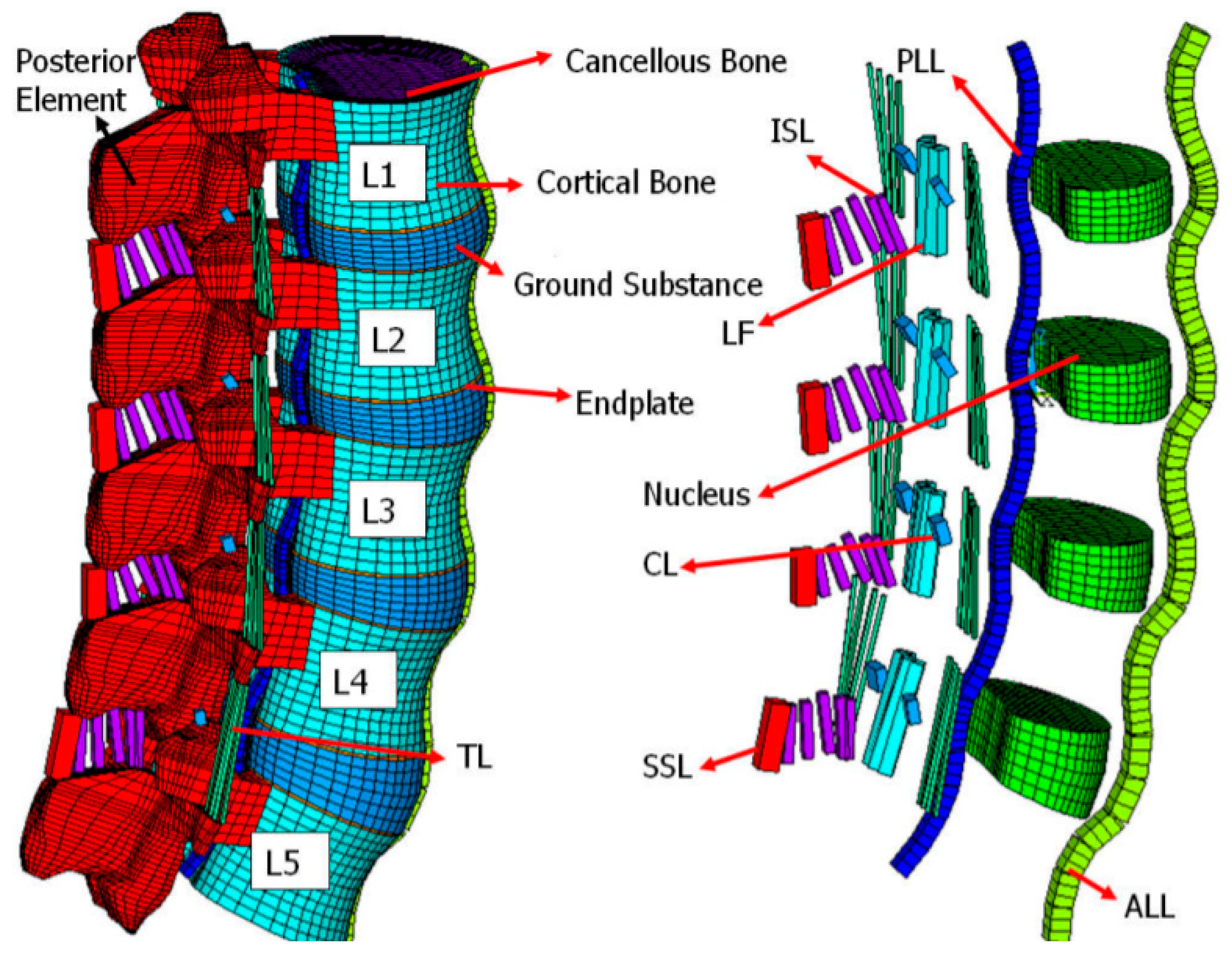
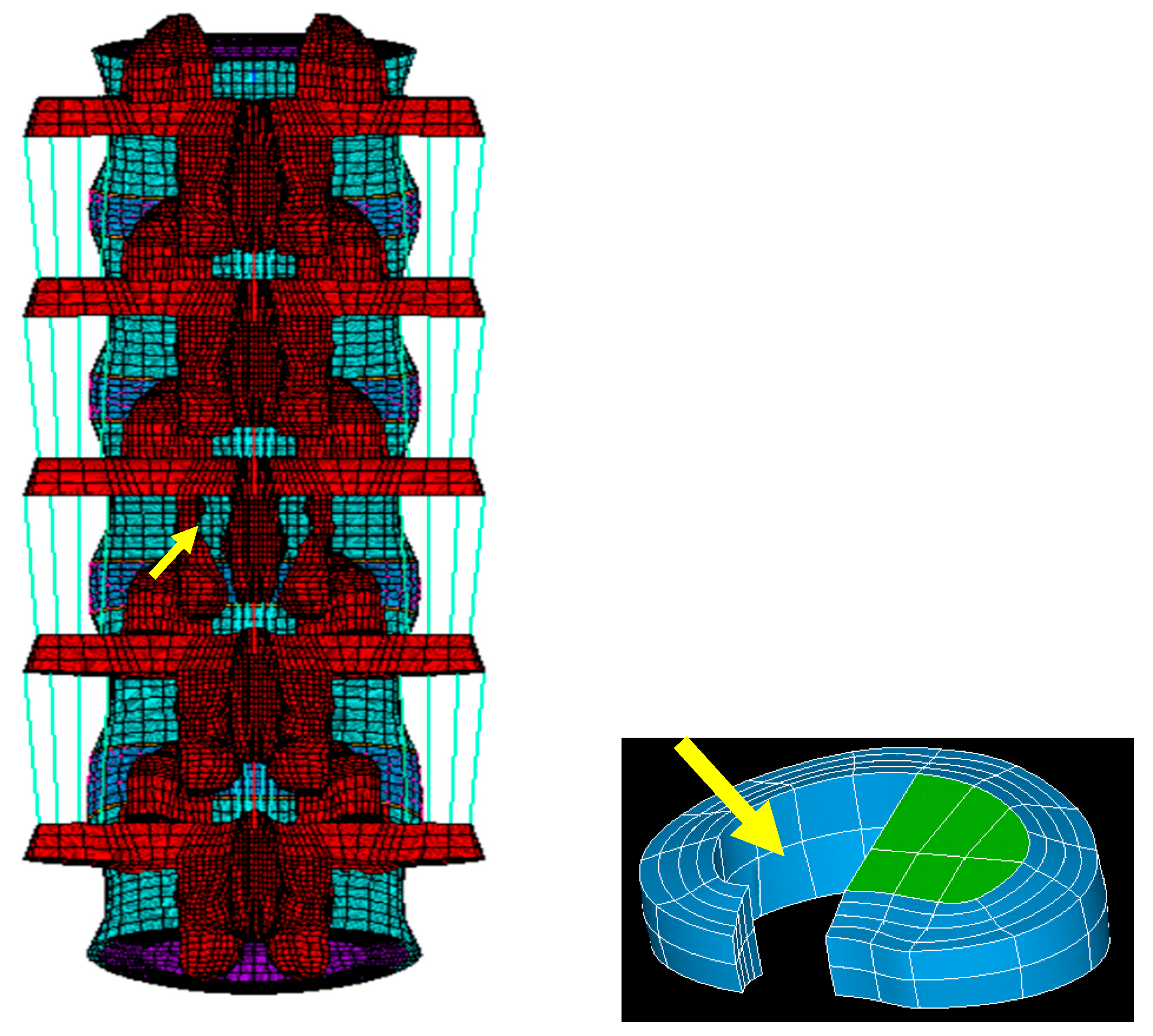
2.1. FE Model of the Intact Lumbar Spine
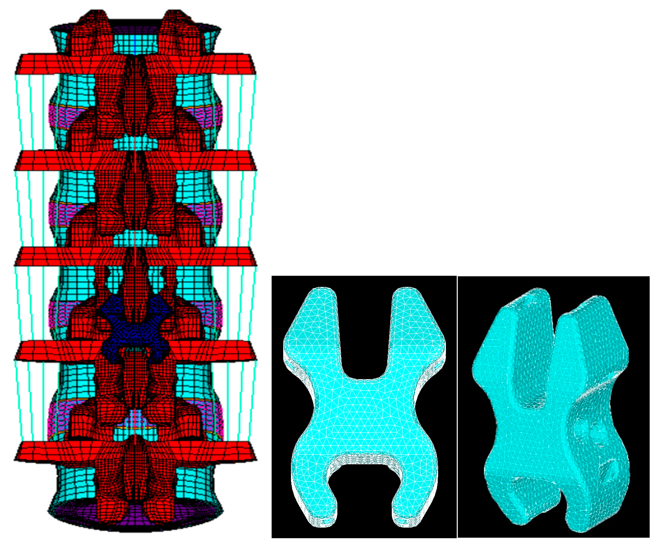
2.2. FE Model of a Lumbar Spine with Decompression and the NIPD
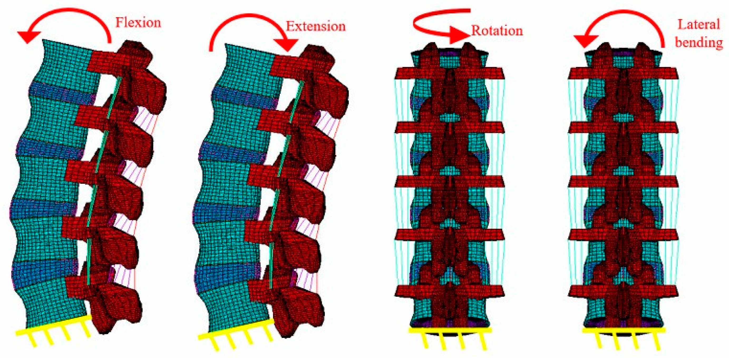
2.3. Boundary and Loading Conditions
3. Results
3.1. Flexion
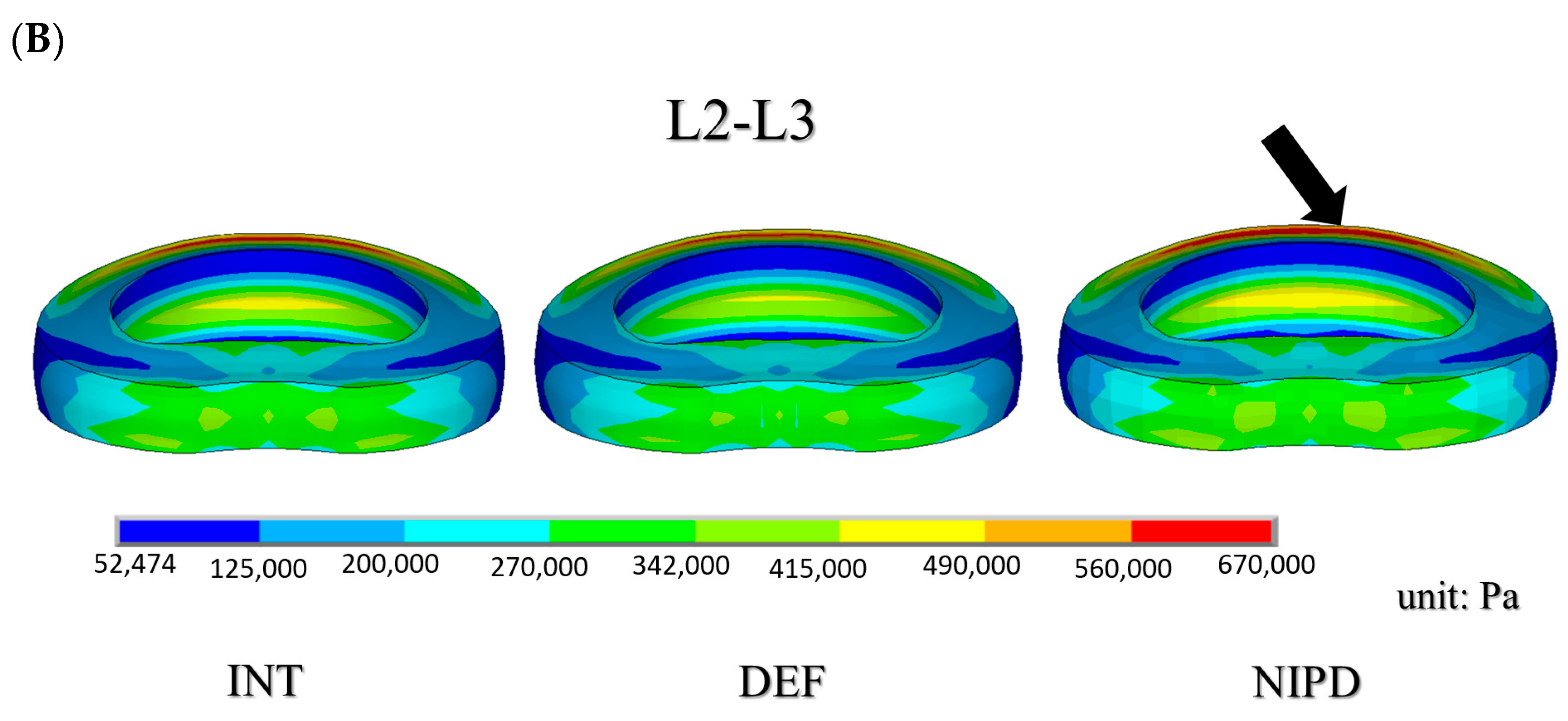
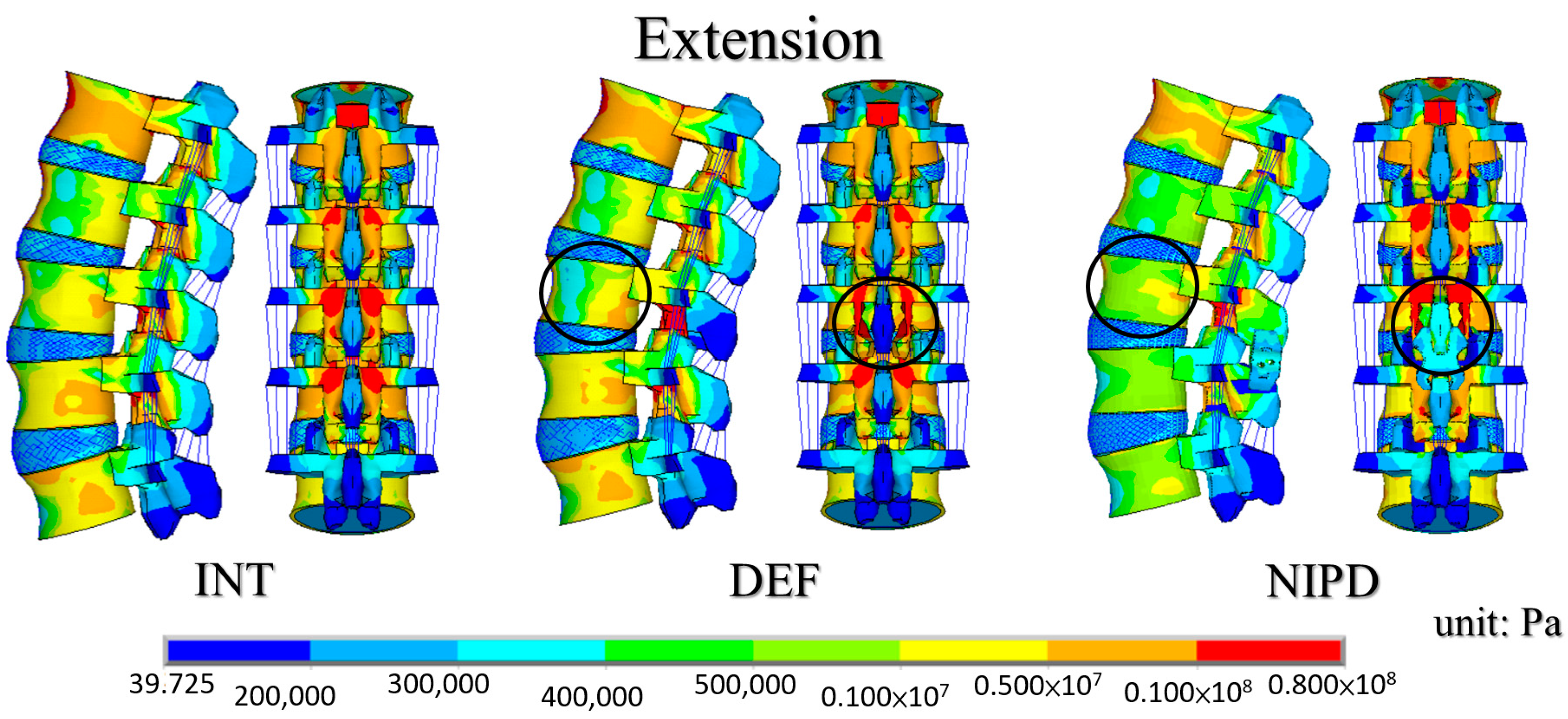
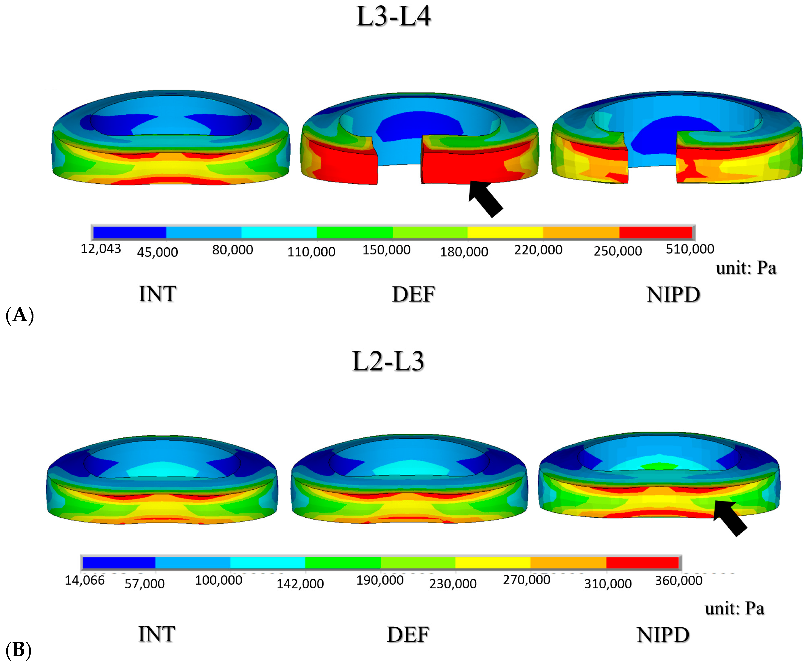
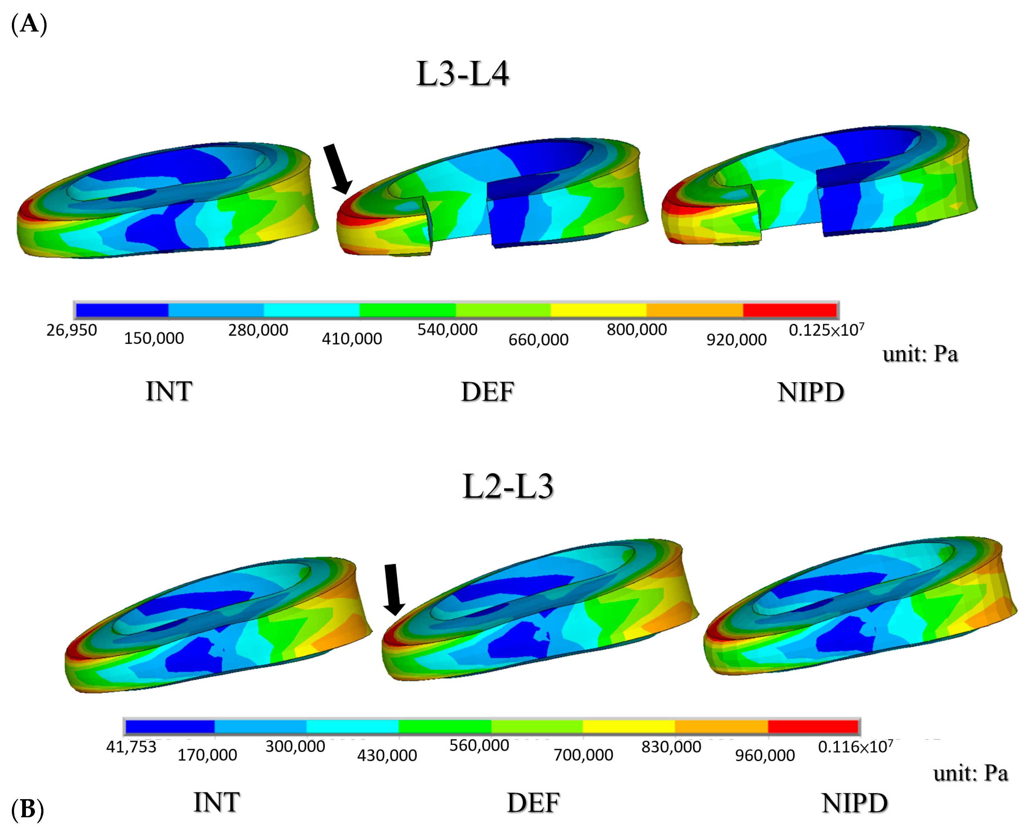
3.2. Extension
3.3. Lateral Bending and Rotation
4. Discussion
5. Conclusions
Author Contributions
Funding
Institutional Review Board Statement
Informed Consent Statement
Data Availability Statement
Conflicts of Interest
References
- Bresnahan, L.; Ogden, A.T.; Natarajan, R.N.; Fessler, R.G. A biomechanical evaluation of graded posterior element removal for treatment of lumbar stenosis: Comparison of a minimally invasive approach with two standard laminectomy techniques. Spine 2009, 34, 17–23. [Google Scholar] [CrossRef]
- Schatzker, J.; Pennal, G.F. Spinal stenosis, a cause of cauda equina compression. J. Bone Joint Surg. Br. 1968, 50, 606–618. [Google Scholar] [CrossRef]
- Tuite, G.F.; Doran, S.E.; Stern, J.D.; Mc Gillicuddy, J.E.; Papadopoulos, S.M.; Lundquist, C.A.; Oyedijo, D.I.; Grube, S.V.; Gilmer, H.S.; Schork, M.A. Outcome after laminectomy for lumbar spinal stenosis. Part II: Radiographic changes and clinical correlations. J. Neurosurg. 1994, 81, 707–715. [Google Scholar] [CrossRef] [PubMed]
- Tuite, G.F.; Stern, J.D.; Doran, S.E.; Papadopoulos, S.M.; Mc Gillicuddy, J.E.; Oyedijo, D.I.; Grube, S.V.; Lundquist, C.; Gilmer, H.S.; Schork, M.A. Outcome after laminectomy for lumbar spinal stenosis. Part I: Clinical correlations. J. Neurosurg. 1994, 81, 699–706. [Google Scholar] [CrossRef] [PubMed] [Green Version]
- Chen, C.S.; Feng, C.K.; Cheng, C.K.; Tzeng, M.J.; Liu, C.L.; Chen, W.J. Biomechanical analysis of the disc adjacent to posterolateral fusion with laminectomy in lumbar spine. J. Spinal. Disord. Tech. 2005, 18, 58–65. [Google Scholar] [CrossRef] [PubMed]
- Lo, H.J.; Chen, H.M.; Kuo, Y.J.; Yang, S.W. Effect of different designs of interspinous process devices on the instrumented and adjacent levels after double-level lumbar decompression surgery: A finite element analysis. PLoS ONE 2020, 15, e0244571. [Google Scholar] [CrossRef] [PubMed]
- Shen, H.; Fogel, G.R.; Zhu, J.; Liao, Z.; Liu, W. Biomechanical analysis of different lumbar interspinous process devices: A finite element study. World Neurosurg. 2019, 127, e1112–e1119. [Google Scholar] [CrossRef]
- Xu, C.; Ni, W.F.; Tian, N.F.; Hu, X.Q.; Li, F.; Xu, H.Z. Complications in degenerative lumbar disease treated with a dynamic interspinous spacer (Coflex). Int. Orthop. 2013, 37, 2199. [Google Scholar] [CrossRef] [PubMed] [Green Version]
- Toth, J.M.; Bric, J.D. An evaluation of the host response to an interspinous process device based on a series of spine explants: Device for Intervertebral Assisted Motion (DIAM). J. Spine Surg. 2019, 5, 483–495. [Google Scholar] [CrossRef] [PubMed]
- Li, C.Y.; Chen, M.Y.; Chang, C.N.; Yan, J.L. Three-dimensional volumetric changes and clinical outcomes after decompression with DIAM implantation in patients with degenerative lumbar spine diseases. Medicine 2020, 56, 723. [Google Scholar]
- Lo, H.J.; Chen, C.S.; Chen, H.M.; Yang, S.W. Application of an interspinous process device after minimally invasive lumbar decompression could lead to stress redistribution at the pars interarticularis: A finite element analysis. BMC Musculoskelet Disord. 2019, 20, 213. [Google Scholar] [CrossRef] [PubMed]
- Chen, C.S.; Shih, S.L. Biomechanical analysis of a new lumbar interspinous device with optimized topology. Med. Biol. Eng. Comput. 2018, 56, 1333–1341. [Google Scholar] [CrossRef] [PubMed]
- Guo, L.X.; Yin, J.Y. Finite element analysis and design of an interspinous device using topology optimization. Med. Biol. Eng. Comput. 2019, 57, 89–98. [Google Scholar] [CrossRef] [PubMed]
- Bae, I.S.; Bak, K.H.; Chun, H.J.; Ryu, J.I.; Park, S.J.; Lee, S.J. Biomechanical analysis of a newly developed interspinous process device conjunction with interbody cage based on a finite element model. PLoS ONE 2020, 15, e0243771. [Google Scholar]
- Shen, H.; Fogel, G.R.; Zhu, J.; Liao, Z.; Liu, W. Biomechanical analysis of lumbar fusion with proximal interspinous process device implantation. Int. J. Numer. Method Biomed. Eng. 2021, 37, e3498. [Google Scholar] [CrossRef] [PubMed]
- Zhong, Z.C.; Hung, C.; Lin, H.M.; Wang, Y.H.; Huang, C.H.; Chen, C.S. The influence of different magnitudes and methods of applying preload on fusion and disc replacement constructs in the lumbar spine: A finite element analysis. Comput. Methods Biomech. Biomed. Eng. 2013, 16, 943–953. [Google Scholar] [CrossRef]
- Rohlmann, A.; Neller, S.; Claes, L.; Bergmann, G.; Wilke, H.J. Influence of a follower load on intradiscal pressure and intersegmental rotation of the lumbar spine. Spine 2001, 26, E557–E561. [Google Scholar] [CrossRef] [PubMed]
- Panjabi, M.M. Hybrid multidirectional test method to evaluate spinal adjacent-level effects. Clin. Biomech. 2007, 22, 257–265. [Google Scholar] [CrossRef]
- Tai, C.L.; Hsieh, P.H.; Chen, W.P.; Chen, L.H.; Chen, W.J.; Lai, P.L. Biomechanical comparison of lumbar spine instability between laminectomy and bilateral laminotomy for spinal stenosis syndrome—An experimental study in porcine model. BMC Musculoskelet Disord. 2008, 9, 84. [Google Scholar] [CrossRef] [PubMed] [Green Version]
- Zander, T.; Rohlmann, A.; Klöckner, C.; Bergmann, G. Influence of graded facetectomy and laminectomy on spinal biomechanics. Eur. Spine J. 2003, 12, 427–434. [Google Scholar] [CrossRef] [Green Version]
- Goel, V.K.; Nishiyama, K.; Weinstein, J.; Liu, Y.K. Mechanical properties of lumbar spinal motion segments as affected by partial disc removal. Spine 1986, 11, 1008–1012. [Google Scholar] [CrossRef] [PubMed]
- Shih, S.L.; Liu, C.L.; Huang, L.Y.; Huang, C.H.; Chen, C.S. Effects of cord pretension and stiffness of the Dynesys system spacer on the biomechanics of spinal decompression- a finite element study. BMC Musculoskelet Disord. 2013, 14, 191. [Google Scholar] [CrossRef] [PubMed] [Green Version]
- Swanson, K.E.; Lindsey, D.P.; Hsu, K.Y.; Zucherman, J.F.; Yerby, S.A. The effects of an interspinous implant on intervertebral disc pressures. Spine 2003, 28, 26–32. [Google Scholar] [CrossRef] [PubMed]
- Minns, R.J.; Walsh, W.K. Preliminary design and experimental studies of a novel soft implant for correcting sagittal plane instability in the lumbar spine. Spine 1997, 22, 1819–1825. [Google Scholar] [CrossRef]


| Material | Element Type | Young’s Modulus (MPa) | Poisson’s Ratio | Area (mm2) |
|---|---|---|---|---|
| Bone | ||||
| Cortical | 8-node SOLID185 | Ex = 11,300 | νxy = 0.484 | - |
| Ey = 11,300 | νxz = 0.203 | - | ||
| Ez = 22,000 | νyz = 0.203 | |||
| Gx = 3800 | ||||
| Gy = 5400 | ||||
| Gz = 5400 | ||||
| Cancellous | 8-node SOLID185 | Ex = 140 | νxy = 0.45 | - |
| Ey = 140 | νxz = 0.315 | |||
| Ez = 200 | νyz = 0.315 | |||
| Gx = 48.3 | ||||
| Gy = 48.3 | ||||
| Gz = 48.3 | ||||
| Posterior element | 8-node SOLID185 | 3500 | 0.25 | - |
| Disc | ||||
| Nucleus pulposus | 8-node SOLID185 | 1.66 | 0.499 | - |
| Ground Substance | 8-node SOLID185 | 5.36 | 0.45 | - |
| C10 = 0.42 | C01 = 0.105 | |||
| Annulus Fibers | 2-node LINK10 | |||
| Outermost | 550 | - | 0.76 | |
| Second | 495 | - | 0.5928 | |
| Third | 412.5 | - | 0.4712 | |
| Innermost | 357.5 | - | 0.3572 | |
| Endplate | 8-node SOLID185 | 24 | 0.4 | - |
| Ligament | 2-node LINK10 | |||
| ALL | 7.8 | - | 24 | |
| PLL | 10 | - | 14.4 | |
| TL | 10 | - | 3.6 | |
| LF | 15 | - | 40 | |
| ISL | 10 | - | 26 | |
| SSL | 8 | - | 23 | |
| CL | 7.5 | - | 30 |
| INT Moment: 4.8 Nm | DEF Moment: 4.5 Nm | NIPD Moment: 5.4 Nm | ||||
|---|---|---|---|---|---|---|
| ROM (degree) | ||||||
| L1–L2 | 3.25 | 3.11 | 3.50 | |||
| L2–L3 | 3.30 (100%) | 3.13 (95%) | 3.45 (105%) | |||
| L3–L4 | 3.30 (100%) | 3.64 (110%) | 2.72 (82%) | |||
| L4–L5 | 4.73 | 4.71 | 5.10 | |||
| Total | 14.58 | 14.59 | 14.77 | |||
| Stiffness (Nm/degree) | ||||||
| L3–L4 | 1.45 (100%) | 1.24 (86%) | 1.99 (137%) | |||
| Disc max. stress (KPa) | ||||||
| L2–L3 | 631 (100%) | 604 (96%) | 664 (105%) | |||
| L3–L4 | 535 (100%) | 540 (101%) | 500 (93%) | |||
| Facet joint force (N) | ||||||
| Left | Right | Left | Right | Left | Right | |
| L2–L3 | 0 | 0 | 0 | 0 | 0 | 0 |
| L3–L4 | 0 | 0 | 0 | 0 | 0 | 0 |
| INT Moment: 4.5 Nm | DEF Moment: 4.5 Nm | NIPD Moment: 5.1 Nm | ||||
|---|---|---|---|---|---|---|
| ROM (degree) | ||||||
| L1–L2 | 2.12 | 2.12 | 2.29 | |||
| L2–L3 | 1.76 (100%) | 1.79 (102%) | 1.91 (109%) | |||
| L3–L4 | 1.37 (100%) | 1.69 (123%) | 1.05 (77%) | |||
| L4–L5 | 0.92 | 0.81 | 1.27 | |||
| Total | 6.17 | 6.41 | 6.52 | |||
| Stiffness (Nm/degree) | ||||||
| L3–L4 | 3.28 (100%) | 2.67 (81%) | 4.85 (148%) | |||
| Disc max. stress (KPa) | ||||||
| L2–L3 | 355 (100%) | 357 (100%) | 356 (100%) | |||
| L3–L4 | 281 (100%) | 505 (179%) | 381 (135%) | |||
| Facet joint force (N) | ||||||
| Left | Right | Left | Right | Left | Right | |
| L2–L3 | 26 | 26 | 26 | 26 | 42 | 41 |
| L3–L4 | 36 | 36 | 36 | 35 | 15 | 14 |
| INT Moment: 12.9 Nm | DEF Moment: 12.6 Nm | NIPD Moment: 12.6 Nm | ||||
|---|---|---|---|---|---|---|
| ROM (degree) | ||||||
| L1–L2 | 6.55 | 6.41 | 6.41 | |||
| L2–L3 | 5.89 (100%) | 5.75 (98%) | 5.76 (98%) | |||
| L3–L4 | 5.51 (100%) | 5.74 (104%) | 5.70 (103%) | |||
| L4–L5 | 5.16 | 5.19 | 5.20 | |||
| Total | 23.11 | 23.09 | 23.07 | |||
| Stiffness (Nm/degree) | ||||||
| L3–L4 | 2.34 (100%) | 2.20 (94%) | 2.21 (96%) | |||
| Disc max. stress (KPa) | ||||||
| L2–L3 | 1110 (100%) | 1080 (97%) | 1090 (98%) | |||
| L3–L4 | 1050 (100%) | 1240 (118%) | 1220 (116%) | |||
| Facet joint force (N) | ||||||
| Left | Right | Left | Right | Left | Right | |
| L2–L3 | 29 | 20 | 24 | 17 | 24 | 16 |
| L3–L4 | 15 | 3 | 13 | 2 | 18 | 1 |
| INT Moment: 1.2 Nm | DEF Moment: 1.2 Nm | NIPD Moment: 1.2 Nm | ||||
|---|---|---|---|---|---|---|
| ROM (degree) | ||||||
| L1–L2 | 0.82 | 0.82 | 0.82 | |||
| L2–L3 | 0.82 (100%) | 0.82 (100%) | 0.82 (100%) | |||
| L3–L4 | 1.01 (100%) | 1.29 (128%) | 1.17 (116%) | |||
| L4–L5 | 1.22 | 1.23 | 1.28 | |||
| Total | 3.87 | 4.16 | 4.09 | |||
| Stiffness (Nm/degree) | ||||||
| L3–L4 | 1.19 (100%) | 0.93 (78%) | 1.03 (86%) | |||
| Disc max. stress (KPa) | ||||||
| L2–L3 | 211 (100%) | 210 (100%) | 210 (100%) | |||
| L3–L4 | 271 (100%) | 281 (105%) | 278 (104%) | |||
| Facet joint force (N) | ||||||
| Left | Right | Left | Right | Left | Right | |
| L2–L3 | 0 | 15 | 0 | 15 | 0 | 15 |
| L3–L4 | 0 | 13 | 0 | 12 | 0 | 8 |
| Flexion | Extension | Rotation | Lateral Bending | |
|---|---|---|---|---|
| DIAM [11] | 110% | 117% | 109% | 116% |
| NIPD | 105% | 77% | 116% | 103% |
Publisher’s Note: MDPI stays neutral with regard to jurisdictional claims in published maps and institutional affiliations. |
© 2021 by the authors. Licensee MDPI, Basel, Switzerland. This article is an open access article distributed under the terms and conditions of the Creative Commons Attribution (CC BY) license (https://creativecommons.org/licenses/by/4.0/).
Share and Cite
Wei, H.-W.; Chuang, S.-M.; Chen, C.-S. Biomechanical Evaluation of the Lumbar Spine by Using a New Interspinous Process Device: A Finite Element Analysis. Appl. Sci. 2021, 11, 10486. https://0-doi-org.brum.beds.ac.uk/10.3390/app112110486
Wei H-W, Chuang S-M, Chen C-S. Biomechanical Evaluation of the Lumbar Spine by Using a New Interspinous Process Device: A Finite Element Analysis. Applied Sciences. 2021; 11(21):10486. https://0-doi-org.brum.beds.ac.uk/10.3390/app112110486
Chicago/Turabian StyleWei, Hung-Wen, Shao-Ming Chuang, and Chen-Sheng Chen. 2021. "Biomechanical Evaluation of the Lumbar Spine by Using a New Interspinous Process Device: A Finite Element Analysis" Applied Sciences 11, no. 21: 10486. https://0-doi-org.brum.beds.ac.uk/10.3390/app112110486