
A Conceptual Design Methodology for e-VTOL Aircraft for Urban Air Mobility
by
 , , ,
, , ,
Giuseppe Palaia
1,* ,
,
Karim Abu Salem
1 ,
,
Vittorio Cipolla
1,
Vincenzo Binante
2 and
Davide Zanetti
2 1
Department of Civil and Industrial Engineering, University of Pisa, Via G. Caruso 8, 56122 Pisa, Italy
2
SkyBox Engineering, Via G. Caruso 8, 56122 Pisa, Italy
*
Author to whom correspondence should be addressed.
Appl. Sci. 2021, 11(22), 10815; https://0-doi-org.brum.beds.ac.uk/10.3390/app112210815
Submission received: 4 October 2021
/
Revised: 3 November 2021
/
Accepted: 11 November 2021
/
Published: 16 November 2021
(This article belongs to the Special Issue Advances in Aerial, Space, and Underwater Robotics)
Abstract
:Recent progress of electric systems has raised attention towards hybrid-electric and full-electric aircraft. Nevertheless, the current low battery energy density limits the application of these propulsive architectures to large transport aircraft. In the context of the general aviation category, full-electric aircraft for the so-called Urban Air Mobility scenario are gaining increasing interest. These air taxis, also called e-VTOL, are conceived to exploit vertical take-off and landing capabilities, to carry people from one point to another, typically within the same city. In this paper, a new conceptual design methodology for urban air vehicles is presented and applied to an innovative convertiplane, called TiltOne, based on a box-wing architecture coupled with tilt-wing mechanisms. Several TiltOne configurations have been designed according to the current regulations imposed by European Union Aviation Safety Agency, and sensitivity analyses have been carried out on the varying main design parameters, such as wing loading and propellers’ disk loading, as well as main top-level aircraft requirements. The results provide an overview for today’s operational capabilities of such aircraft and, in addition, depict possible scenarios for a near-future horizon, based on the assumption of increased performance levels for the electric powertrain components. In such scenario, two different concepts of operations are analysed and discussed: the first is based on a given design range, long enough to cover the urban distances; the second is conceived to exploit the capability of flying multiple shorter missions with a single battery charge. The designed TiltOne configurations derived from these different approaches are presented, highlighting their potential capabilities and possible drawbacks.
1. Introduction
The continuous improvement of electrical powertrains, in particular in terms of specific energy density of battery packages, has created numerous opportunities in different fields, such as the automotive field [1,2]. The adoption of hybrid-electric (i.e., coupled with thermal engine) or full-electric propulsion systems can reduce direct noxious emission of road transportation [1]. Although some concerns arise about the power distribution network capability [1], several car manufacturers are planning to sell only full-electric vehicles by the year 2035 [3]. The great potential demonstrated by the automotive field has captured the attention of the aviation world, and today electric propulsion is widely investigated in the aeronautic field [4,5,6]. In Europe, several research projects have been financed [7,8,9,10,11,12,13,14], aiming to provide feasibility studies and assess the benefits of electric aircraft and speed up their entry-to-service. In this context, the electrification of general aviation aircraft is increasing, proceeding along the path traced by NASA in 2003. In [15], air vehicles are described as a viable solution to alleviate congestion and enhance the quality of life in highly populated urban scenarios. The application of air vehicles to goods and people transportation in urban scenarios has been defined as Urban Air Mobility (UAM) [16,17,18]. In the United States, UAM is part of the Advanced Air Mobility (AAM) programmes: Federal Aviation Administration (FAA), NASA and industry are collaborating to define a new aviation market, which exploits electric aircraft for intra-city (in the same city) and inter-city (between cities) transportation of people and goods [17,19]. In 2016, Uber published a white paper on UAM, describing the benefits, in terms of time saved, emerging from the introduction of air transportation of people in high urban density scenarios and the main hurdles to enable UAM [18]. In [20], NASA reported how air transportation can mitigate the congestion by consistently reducing the travelling time. The air transport envisioned in [18,20] is based on a ride-hailing service, in which people can book an air taxi using a mobile application. Although such service can be provided using vehicles with a pilot on-board, the long term vision consists of using air taxis capable to fly autonomously within the cities. On this point, it is worth emphasizing that if on the one hand the future capabilities of autonomous systems will allow air taxis to operate without human oversight, on the other hand, operator’s accountability will certainly be a legal requirement. As a consequence, the presence of a “ground pilot”, i.e., a supervisor located in a ground station, will also be needed in the future.
To accomplish the mission in the most flexible way, air taxis have to be provided with Vertical Take-Off and Landing (VTOL) capabilities; therefore, they are sometimes referred to as “e-VTOL” to recall the electric propulsion. According to [18], the challenges that UAM needs to face for bringing benefits to travellers and the environment are: (i) reduced flight time in comparison to road transport alternatives; (ii) noise level below 67 dB; (iii) no noxious atmospheric emissions in flight; (iv) air vehicle must be safe and reliable. Many companies (e.g., AIRBUS, Lilium, Joby Aviation) are developing several configurations to satisfy the above requirements [21,22]; among them, two main categories can be recognized: rotary wing and fixed wing aircraft. Multi-rotors (Figure 1d) or helicopters belong to the first category; tilt-wing (Figure 1a), tilt-rotor (Figure 1c) and “lift + cruise” (Figure 1b) to the second one [23,24].
Multi-rotors (M-R) are equipped with three or more propellers, which generate thrust and sustain the vehicle during hovering and forward flight.
Tilt-rotor (T-R) and tilt-wing (T-W), also called convertiplanes, mix the capability of rotary-wing and fixed-wing aircraft: in forward flight they are similar to a propeller airplane (achieving higher range and speed with respect to M-R), whereas to take-off/land they are similar to rotary-wing aircraft. Tilt-rotor aircraft perform a rotation of the propulsors to switch from fixed-wing to the rotary-wing layout (and vice versa); in tilt-wing, instead, lifting surfaces and propulsors are integral components, hence they rotate together during the transition. In such case, the movable lifting surface can be only a portion of an entire wing and it can be connected to one or more propulsors.
A “lift + cruise” (L + C) e-VTOL is an aircraft which exploits some propellers for take-off and landing and other ones to generate thrust during cruise.
The main advantages and drawbacks of each configuration are detailed in Table 1, in which the “lift + cruise” case has been used as baseline, since it combines some features of the multi-rotor with other of the convertiplanes. If compared to convertiplanes, the “lift + cruise” solution allows to reduce the complexity [24], but shows some penalties in terms of cruise efficiency, because of the additional drag introduced by the rotors used in the hovering phase [29]. In terms of internal comfort, the inclination required by multi-rotors to accelerate and decelerate during the transition phases can be a disadvantage, whereas tilt-wing/rotor can have a better response since the fuselage can be kept in a horizontal position during the transitions. For more details, the reader can refer to [24].
To enable UAM, several challenges concerning infrastructure requirements, regulation, air traffic management and public acceptance must be addressed.
Specific ground infrastructures, designed for VTOL operations and sometimes called “vertiports”, are necessary to operate the air taxis [24]. As described in [18,31], even replacing the existing heliports with vertiports, the ground infrastructures would not be sufficient to meet the envisaged market demand [18], so new vertiports should find their place in the urban context. Currently, the location of new vertiports is an open problem, which needs to be further investigated [31]. Moreover, the readaptation of existing heliports must guarantee safety during take-off and landing phase if multiple departure/arrivals are expected [18].
Starting from helicopter regulations, aviation safety authorities, such as EASA in Europe and FAA in the United States, have started drafting the definition of e-VTOL air taxis certification rules. EASA has produced a first draft in 2019 [32], defining some general requirements such as maximum take-off weight of 3175 kg and maximum number of passengers equal to nine. Recently, a means of compliance has been published where more regulatory aspects are detailed [33]. FAA, together with NASA and stakeholders, has released a first draft defining the main indications for air traffic management [34]. Several manufacturers, such as Airbus, Boeing-Aurora and eHANG, have the long term goal of introducing air taxis capable to fly autonomously (i.e., without the presence of a pilot on-board), but it is more likely to assume that in an initial phase they will have a pilot on-board. When technology reaches a level of maturity capable to mitigate the safety and public acceptance concerns, air taxis will be suitable for autonomous operations. In this context, the word autonomous indicates that aircraft will be remotely controlled (enabling the Beyond Visual Flight Rules, BVFR) from a central command where a continuous exchange of data is performed [17,23,28,35].
On the air traffic side, the management of several air taxis in a high-density flights scenario can be an actual showstopper; in particular, three aspects can be identified as critical issues for UAM: the scalability of the air traffic control system, the creation of adequate ground infrastructure, and the public acceptance [36], which affect the traffic scheduling.
From the public acceptance standpoint, two main aspects are to be considered: safety during on-ground and in-flight operations and the level of noise perceived in the case of a high-density flight scenario. To guarantee safety and low level of noise, clear regulations and requirements have been prescribed [18,33].
Moving the focus from the operative scenario to the flying vehicle, two main aspects need to be investigated first: the definition of Top-Level Aircraft Requirements (TLARs) and the definition of a design workflow suitable for the early stage of the design process. The definition of TLARs applicable to any type of e-VTOL is not possible, since typical speeds and range intervals depend on the selected aircraft typology (as pointed out in Table 1). As a consequence, the selection of the design mission does not provide a unique result [37,38,39,40]. It is worth highlighting that technological assumptions on electric powertrain play a key role in the aircraft design, so it has to be clearly stated at the beginning of the design.
Full-electric [39,40,41,42,43,44,45] and hybrid-electric [45,46,47,48] VTOL aircraft have been designed adopting different conceptual design methodologies. In Table 2, the main assumptions and models adopted in the conceptual design methodologies found in the literature are reported.
In the first part of this paper, a new conceptual design methodology for the air taxi aircraft category is presented; the proposed methodology exploits physics-based models to achieve accurate results as much as possible. In the aerodynamic model, a VLM method combined with the component build-up method [49], has been implemented in order to estimate the polar drag of conventional and disruptive architectures (e.g., box-wing [55]). Weight estimation has been obtained by a detailed component weight build-up method modified ad-hoc to evaluate the mass of the components of the electrical powertrains. Moreover, aircraft flight performance has been computed by the Euler integration method, ensuring accurate energy consumption evaluation for each phase of the mission. The results of the design procedure are then compared with the outcomes available from the reference literature. Then, the methodology described here is applied to the design of an innovative air vehicle based on box-wing configuration [55,56] called TiltOne. Several configurations have been evaluated, and results from sensitivity analyses to main design parameters, such as propellers’ disk loading and wing loading, and TLARs parameters (speed, range and technological level of electrical system) are widely analysed. Finally, limitations and potential benefits of this urban air vehicle are discussed, together with the analysis of possible operating scenarios.
2. Design Methodology
The workflow developed for the conceptual design of e-VTOL aircraft is depicted in Figure 2. It takes all the main aspects of the aircraft design (e.g., aerodynamics, mission analysis, structural design, propulsion sizing) into account; in particular, the propulsion sizing block has been developed specifically to deal with electric propulsion. Accordingly, five main blocks can be identified:
- TLARs and design parameters: it defines Top-Level Aircraft Requirements (TLARs) and main design variables;
- Mission performance: it evaluates aircraft performance by using flight mechanics equations;
- Weight estimation: it estimates mass breakdown of the configuration by using NASA weight estimation for the general aviation category [60] and literature models for electrical components (e.g., battery mass).
The proposed workflow can be applied to VTOL aircraft of different typologies: tilt-wing, tiltrotor, “lift + cruise” and multirotors. Moreover, it allows to design aircraft with different architectures, such as the conventional wing-tail or the innovative box-wing one.
This latter has two staggered main horizontal wings connected by lateral wing tips and can be provided with VTOL capabilities by implementing a tilt-wing mechanism. Therefore, in far-to-ground operations, the aircraft moves horizontally in “fixed-wing” mode (Figure 3b), whereas in close-to-ground operations it tilts the wings to hover and move vertically, sustained by the thrust generated by the propellers (“multi-rotor mode”, Figure 3a). Hereafter, this e-VTOL box-wing aircraft is simply referred as TiltOne.
It is worth noting that the TiltOne, in fixed-wing mode, can exploit the aerodynamic behaviour of the box-wing architecture, artistically represented in Figure 3, also called “PrandtlPlane”. The box-wing architecture, for the first time applied in 1907 by the pioneer Alberto Santos-Dumont on his prototype “14 bis”, inspired the studies carried out in the 1920s by Ludwig Prandtl [61], who first indicated it as the “best wing system”, i.e., a lifting system capable to minimize the induced drag for given lift and wingspan. Following studies have provided an exact mathematical solution to describe the optimal lift distribution [62] (Figure 4a), hence providing a theoretical support to the aircraft design activities. An example of PrandtlPlane is depicted in Figure 4b, which refers to the case of the two-seater amphibian from the Italian project “IDINTOS”. As shown, the PrandtlPlane has a tailless box-wing architecture with a significant negative stagger (or forward, although less common) [63], which allows the use of the rearmost wing both as lifting surface and horizontal stabilizer. This change allows the architecture to reduce the induced drag but introduces the need for accurate studies on static and dynamic flight stability, as well as new approaches for the structural design, the box-wing being a hyperstatic system.
As detailed in the following, the approach adopted for an initial investigation on the design of a tilt-wing aircraft is based on two main design parameters: the wing loading W/S and the propellers’ disk-loading T/A, defined as in Equations (1) and (2), respectively.
The wing loading is the ratio between the weight of the aircraft Waircraft (which is constant throughout the mission) and the reference surface of the lifting system Sref, which for the box-wing take both front and rear wing area into account. The wing loading is of key relevance as it is directly related to the aerodynamic and aeromechanical performance of the aircraft in fixed wing configuration [66].
The disk loading is the ratio between the thrust of a propeller (Tpropeller), while the aircraft hovers, and the associated disk area (Apropeller), assumes that all the propellers have the same dimensions and performance. This parameter is significant for vertical flight and hovering phases; it is directly related to the power required by the motors in the take-off/landing/hovering phases, but also to the noise footprint [67]. For both these parameters, sensitivity analyses have been carried out regarding the main performance of the TiltOne.
The following sections provide a detailed description of the blocks composing the design workflow presented in the Figure 2.
2.1. TLARs and Design Parameters
The first step of the aircraft design is the definition of the aircraft requirements (e.g., mission range, cruise speed, payload). In the context of the Urban Air Mobility (UAM), the scenario is currently qopen-ended, as the UAM potential market is still under investigation and development [37,38,39,40]. So, at least in the conceptual design phase, TLARs are more related to the type of VTOL and to its potential performance, as shown in [42], which underlines how speed and range requirements substantially change if VTOL architecture changes. In the present study, the TLARs have been initially set according to Table 3, i.e., defining lower and upper limitations for most of the significant parameters.
In addition, due to the relevance of the electrical equipment (e.g., batteries, motors) on the overall aircraft performance, the technological level of the electric system has been set as initial assumption. In particular, two different levels have been considered, one referring to the current technology and the other to the future forecasts, referring to the 2035 time horizon.
2.2. Aerodynamics
The Aerodynamics module evaluates aircraft drag polar, which is necessary to properly evaluate the overall aircraft performance, both in terms of power required (see Section 2.3) and in mission performance (see Section 2.4). The total drag of the aircraft, in fixed-wing configuration, is evaluated by using the software AVL [57], based on a Vortex-Lattice Method (VLM), and the component build-up method [49,58]. Specifically, the induced drag is evaluated by AVL, and parasitic and friction drag is evaluated by the component build-up method. NACA23018 has been selected as airfoil for all the sections of both front and rear wings, whereas NACA0017 has be adopted in the vertical tailplanes. The vertical tip-wings have variable airfoils along their span, since they connect the upper surface of the front wing to the lower surface of the rear wing, and vice versa.
This methodology has already been used for the design of hybrid-electric aircraft; further explanation is detailed in [68].
It is worth emphasising that wing-propeller interactions have not been implemented in the aerodynamic analysis to keep the workflow simple and fast, which are fundamental characteristics of approaches adopted in the early stages of the design.
2.3. Motor Sizing
This module evaluates the power required for the propulsion system, i.e., the electric motors, in each phase of the mission. The TiltOne has 8 propulsion units (propeller, electric motor and control electronics), 4 installed on the aft wing and 4 on the rear wing, as depicted in Figure 5.
The reason for setting the number of propulsors to 8 comes from the assumption that, in multi-rotor mode, the aircraft can be controlled as a quad-rotor with a “X” scheme, which sets the minimum number to 4. In order to increase the safety of the system, an additional group of 4 propulsors is introduced with a side-by-side distribution along the wingspan. This choice has been preferred to other possible alternatives (e.g., coaxial push-pull) since it provides the 4 half-wings with similar airflow conditions along the wingspan. Given the preliminary level of this study, a detailed motor failure analysis has not been carried out, the redundancy given by this double set of 4 propulsors allows to perform a safe landing manoeuvre in case of failure of 1 of the 8 motors, once a proper oversizing is considered.
In fixed-wing mode the TiltOne exploits all the propellers to generate the necessary thrust to the forward flight; however, this assumption can be easily modified. Moreover, as shown in Figure 6, the power requested at cruise is far lower than the take-off phase; accordingly, a variable pitch propeller has been assumed in order to avoid a reduction in propeller efficiency.
The installed power is obtained by using the so-called matching chart: a specific power (P/W)-wing loading (W/S) chart where, for each wing loading, the corresponding specific power is evaluated [59,68]. To use the matching chart, the following steps must be followed:
- Definition of the most power demanding phases;
- Identification of regulations (e.g., FAR), which identify critical conditions that the propulsion system must satisfy, if any;
- Estimation, for each phase, of the requested power;
- Identification of the maximum requested specific power.
According to the list above, four different flight conditions have been considered: take-off (TO), climb (CL), cruise (CR) and stall (ST). During take-off, the aircraft flies in multi-rotor mode; in the other phases the aircraft is in fixed-wing mode. For TO, CL and CR, a mathematical expression of the specific power has been derived as reported in Equations (3)–(5), whereas the maximum wing loading of the configuration is obtained by Equation (6) (referred to the ST). The demonstrations for Equations (3)–(6), are reported in Appendix A.
In Equation (3), is the extra-thrust coefficient, defined as the ratio of the total thrust generated by the propellers to the weight of the aircraft. is a figure of merit of the rotors, defined as the ratio between the induced power (i.e., the power associated to the induced speed, evaluated by means of the disk actuator theory) and the total power given by induced speed, aerodynamic drag acting on the blades, tip losses and other secondary effects [67]. is the propeller efficiency, which has been set to 0.8 [67,68,69,70,71,72] for all the flight phases, as it is assumed that variable pitch propellers are adopted. T/A is the disk loading, already defined in Section 2; g is the acceleration of gravity; is the air density.
In Equation (4), ECL is the lift-to-drag ratio in climb; CLCL is the lift coefficient, and Vz is the rate of climb. W/S is the wing loading, already defined in Section 2.
In Equation (5), ECR and VCR are the lift-to-drag ratio and lift coefficient in cruise, respectively. Vstall is the aircraft stall speed. CLmax is the maximum lift coefficient (with high lift devices deployed).
The requested specific power is given by the Equation (7),
As shown in Equation (3), the take-off specific power does not depend on the wing loading W/S but on the disk loading T/A; this is due to the fact that the during take-off the aircraft is in multi-rotor mode. The air density () affects hover performance, since lower density increases the requested power; in take-off phase, the air density has been evaluated at mean sea level according to the international standard atmosphere (ISA) [69]. The total take-off power is given by the sum of several components (e.g., power fraction due to induced speed and parasitic drag of the blade, tip losses, etc.), and the following procedure has been adopted for its evaluation:
- evaluation of the power fraction due to induced drag by using the disk actuator model;
- estimation of the figure of merit (FoM) according to literature data [67];
- calculation of the total take-off power according to the Equation (3).
The procedure described above is commonly used in the conceptual design phase [30,41,42]; it allows to estimate the total take-off power without designing a rotor blade. As said before, the figure of merit parameter allows to consider all the fraction of power contributions; in this paper, a value of 0.8 has been assumed according to [67].
An extra thrust factor ( has been assigned in order to accomplish the phase also with a motor failure: is set equal to 1.2 so, if a motor fail, the propeller thrust exceeds the MTOW of 5%. Equations (4) and (5) show a dependence of the required specific power for cruise and climb on wing loading, since the aircraft flies in fixed-wing mode. To estimate the maximum wing loading, the following hypotheses have been introduced:
FAR23 regulation has been considered since it is applied for aircraft with MTOW lower than 19,000 pounds and a maximum number of passengers of 19, which is in line with e-VTOL requirements. As detailed in [68], P/W-W/S matching charts can be used to estimate the specific power needed for each wing loading, taking the highest value given by the flight conditions considered. In the TiltOne case, Figure 6 shows the plot of Equations (3)–(6) varying the wing loading; the take-off condition is the most power-demanding for any wing loading value, hence it drives the design of the propulsion system. As an example, the requested specific power for a single case (W/S = 100 kg/m2, dashed black line) has been depicted.
2.4. Mission Performance
The Mission performance module evaluates the aircraft performance in each phase of the design mission. All the assumptions about the design mission are reported in Table 4.
In the phases from (1) to (3), the TiltOne flies in multi-rotor mode, hence sustained by the thrust generated by the propellers. As Figure 6 shows, these phases are the most power demanding, and the power requested has been computed by using Equation (3) setting kT to 1.2 in take-off phase and 1.0 in hovering phase. During the transition phase (3–4), the TiltOne changes the wings layout, going from multi-rotor to fixed-wing mode, and at the same time the aircraft exhibits a constant longitudinal acceleration. This phase ends when the TiltOne reaches the climb speed, which is calculated according with the assumptions on rate of climb (RoC) and lift coefficient introduced in the following. Because of the unsteady motions of the tilting wings as well as of the whole aircraft, the mathematical models of this phase can be complex, and it needs substantial information, which is not available in the early phase of the design process. To cope and reduce the complexity of the mathematical formulation, two assumptions have been considered:
- the aircraft has a constant longitudinal acceleration of 2 m/s2, as assumed in [30];
- the aircraft total thrust decreases linearly, from the thrust generated in multi-rotor mode to the thrust generated in fixed-wing mode at the beginning of the climb phase (Figure 7);
- the power requested to accomplish the phase is given by the time integral of the total provided thrust and the aircraft speed, maintaining a constant value for the propeller efficiency (.8) and assuming no losses in the mechanical transmission.
During climb, cruise and descent phases, the aircraft performance is computed by using the flight mechanic equations developed for fixed-wing airplanes; for more details, the reader can refer to [73]. During climb, the aircraft lift coefficient is constant, and it is provided by the Equation (8), where is the lift coefficient which minimizes the requested power in horizontal flight. This value is evaluated according to the following procedure:
- definition of a set of aircraft speed values;
- evaluation of the lift coefficient which trims the aircraft in vertical direction for each value of the aircraft speed;
- estimation of the drag coefficient by means from the polar curve calculated in the Aerodynamic module;
- estimation of the requested power for each drag coefficient-aircraft speed combination;
- evaluation of the lift coefficient which minimizes the requested power ().
is a safety factor, which prevents reaching the stall condition (for the unflapped configuration) during the climb phase. In this study, it has been assumed equal to 1.2.
Constant rate of climb (RoC) and rate of descent (RoD) equal to 500 ft/min have been assumed, in accordance with [38]. The diversion phase is similar to the standard mission, except for the cruise height, which is 300 m AGL. All the phases have been simulated by using Euler integration method with a proper time discretization for each phase. Accordingly, the total energy required for mission has been computed by Equation (9), where is the time-history of the power provided by batteries during the mission and is the battery discharge efficiency.
2.5. Weight Estimation
The Weight estimation module evaluates the aircraft mass breakdown. The MTOW is computed by using the Equation (10).
The battery mass () is computed considering the energy necessary to accomplish the mission, provided by Equation (9), assuming an additional 5% for the energy consumption due to avionics and flight instruments. This value can be better evaluated once physic-based models are developed, as done in [74] for example.
For safety reasons, the minimum state of charge at the end of the design mission (SoCfin) is set to 20%, whereas the initial state of charge (SoCin) is 100%.
Battery mass evaluation is reported in Equation (11), by dividing the total required energy by the battery energy density (BED), which depends on the technology assumptions and, as the paper shows, has a significant impact on aircraft performance.
Payload mass (Mpay) is evaluated by using Equation (12), where Nmax is the maximum number of passengers carried by the TiltOne, as specified in the TLARs. Mpax is the mass of single passenger, set equal to 100 kg [38,70].
Operative empty weight (OEW) has been calculated according to the Equation (13).
and are the structural and system weight, respectively. , and are transition system, thermal management system and electric components weight, respectively. To compute structural and system weight, the tool FLOPS developed by NASA has been used [60]: According to [60], structural weight includes wings, tails, fuselage, nacelle and paint; system weight considers control surfaces actuators, instruments, avionics, anti-icing and furnishing. It is worth noting that the classical model for cantilever wings overestimates the structural mass of the box-wing architecture [75,76,77,78], so the results reported in this paper (e.g., estimation of MTOW) are conservative. This tool is versatile since it can be used for aircraft ranging from general aviation to transport aircraft categories; in this paper, the general aviation category has been selected, since the weight formulation, adopted in this paper and described in FLOPS, have been specifically derived for general aviation aircraft category. The NASA’s tool does not take electric components of the powertrain (i.e., electric motor, ESC, BMS, motors, cables and propeller) into account, thus ad hoc models have been used and reported in Equations (15)–(18).
Equations (15) and (16) estimate the mass of the battery management system () and electric motors (), respectively; is the maximum power supplied by the battery pack (measured in kW); BMSPD is the battery management system power density, is the power absorbed by the electric motor, and EMPD is the electric motor power density. Equation (17) has been introduced to evaluate mass of power and sensor cables , according to the results of the VAHANA project [78]; in particular, CPD is the cable power density, and is the cable length. An issue of the adoption of electric propulsion is the overheating of the battery pack; generally, a thermal management system must be designed to avoid it, since battery overheating can be detrimental for the battery’s life [79] and for the overall safety. The design of the battery Thermal Management System (TMS) goes beyond the aim of this paper, so Equation (18) has been selected from the available literature ([80]) to estimate the mass of the battery thermal management system , starting from the maximum power supplied by the battery pack () and the battery discharge efficiency (). Propeller mass has been evaluated by using data of propeller manufacturers [81,82,83], and a regression model, with least square method, has been used to relate the propeller mass to the maximum power absorbed by the propeller (Figure 8).
The mass estimation of the actuator system () needed for the transition from fixed-wing to multi-rotor mode (and vice versa) is not trivial since it can be only designed in a more advanced design phase and no literature data are available for this type of e-VTOL. It has been assumed that its mass corresponds to the 5% of the total MTOW.
3. Comparisons with Literature Data
To compare the design workflow, the three tilt-wing e-VTOL aircraft described in [45] has been considered. The same assumptions of the reference paper have been introduced, and information not directly provided (e.g., wing taper ratio, fuselage length and diameter) has been reasonably assumed or derived from the reference source. The comparisons between the results computed with the proposed design procedure and the reference data from [45] are shown in Table 5, Table 6 and Table 7.
The comparisons highlight that the proposed methodology:
- estimates a higher OEW/MTOW fraction since it calculates each single component by using physic-based equations, whereas in the reference paper a quite simple relation on OEW/MTOW fraction is assumed, and it is not stated if it accounts for components such us cables, TMS, BMS, etc.;
- shows a higher MTOW estimation in comparison to the reference paper in all the examined cases, which is mainly due to the higher OEW/MTOW fraction estimation;
- slightly underestimates the battery mass fraction, but the discrepancies are small.
In conclusion, compared to the considered reference case, the proposed methodology shows sound predictions with differences that can be reasonably explained.
4. Sensitivity Analyses for Design Space Exploration
This section describes the application of the sizing procedure presented in Section 2 to a case study related to the TiltOne. The choice of this specific architecture lies in a peculiar combination of capabilities, which makes it worth investigation. These are:
- the possibility to exploit the advantages of the box-wing, i.e., the minimization of induced drag for given wingspan and lift, in several ways depending on the given priorities and needs:
- the possibility to exploit one of the theoretical advantages of a tilt-wing system, consisting of:
- o
- the transition phases can be performed with the fuselage in horizontal position;
- o
- the possibility to exploit a tilt-wing system, which allows vertical take-off/landing, and hovering, but also to fly with the high aerodynamic efficiencies typical of fixed-wing aircraft when flying in cruise.
As described in the introduction, these air vehicles are conceived to operate autonomously in the Urban Air Mobility sector, i.e., for the commercial transport of passengers on urban routes. For this purpose, following the studies on possible operating scenarios and the analysis of the related literature [37,38,39,40], the Top Level Aircraft Requirements (TLARs) reported in Table 8 have been considered.
Table 8 shows that:
- the propulsion system adopted is totally electric;
- the number of motors/propellers selected is equal to eight, with four propellers placed on the front wing and four on the rear wing (as explained in Section 2.3);
- given the several unknowns about the future UAM scenario, it has been decided not to constrain the design with a given reference mission, but to allow the variation of mission range and the cruise speed within the intervals indicated in Table 8.
In addition to the main requirements defined in Table 8, there are also further constraints that have a direct impact on the design of the flying machine; the main ones are summarized in Table 9, which highlights the following aspects:
- the latest release of European regulations for Urban Air Mobility [32] has been considered to set the upper limit of MTOW equal to 3175 kg;
- a constraint on the maximum wingspan, which is fundamental when considering the compatibility and the use of “vertiport” facilities, has been derived from the feasibility studies carried out by Uber Elevate [38]; however, as the study and development of vertiport infrastructure is rapidly evolving, and currently there are no effective regulations or constraints, this constraint can be reviewed later and in more detailed stages of the design process;
- a minimum clearance between propellers (see Figure 9) has been set to ensure good efficiency of the propulsion system; in fact, as shown in [84], an overlap of propeller tips leads to an increase in the power required for flight. However, establishing the minimum distance in the conceptual design phase is a non-trivial problem that requires advanced analysis to optimise performance in both vertical and horizontal flight; therefore, a minimum distance of 0.1 m has been set as an initial design guideline. The fulfilment of general prescriptions on minimum axial and radial clearances between propellers and other aircraft components and structures have been implemented in the design process.
The clearance between propellers has been evaluated according to Equation (19).
Given the conceptual nature of this study, which aims to explore the actual applicability of the box-wing tilt-wing concept to the Urban Air Mobility sector, no more detailed constraints have been introduced. The technological parameters related to electric motors, components and batteries have a significant influence on the performance of an aircraft with hybrid-electric or full-electric propulsion [45,68]. Many studies, research and advancements have been made to highlight the capabilities, and especially the limitations, of the state of the art in this field and to predict possible developments and achievable benefits in the near future [4,5,6]. For this reason, a two-step analysis of the actual operability of a box-wing tilt-wing aircraft for Urban Air Mobility has been performed: in the first part, the conceptual design is carried out assigning to technological parameters values from the current state of the art; in the second part, technological characteristics of the electric powertrain expected for the time horizon of 2035, are taken into account [85].
For each technology scenario, sensitivity analyses to the design parameters, i.e., wing loading and propellers’ disk loading, have been performed. In addition, since for design range and cruise speed possible intervals have been defined (see Table 8), sensitivity analyses to these mission parameters have been carried out too.
The objective of such analyses, reported in the following, is to draw general trends that can provide guidelines useful in the early stage of the design process.
4.1. Current Powertrain Technology
In this section, the results of the conceptual design of the TiltOne with current powertrain technology are presented. The design has been carried out assuming the TLARs reported in Table 8, whereas values of the technological parameters are reported in Table 10. The main assumptions concerning the design mission are detailed in Table 11.
Sensitivity analyses to wing loading (varying from 70 kg/m2 to 100 kg/m2) and propellers’ disk loading (varying from 40 kg/m2 to 70 kg/m2) have been carried out, and the results are reported in the following wing loading-disk loading charts. In these charts, each point corresponds to a configuration with different wing loading and disk loading; moreover, each aircraft is designed according to the workflow depicted in Figure 2 and substantial information can be extracted, such as MTOW, wingspan and battery mass. A general picture is shown in in Figure 10, where several variables have been considered; namely, MTOW (Figure 10a), battery mass (Figure 10b), propeller clearance (Figure 10c), wingspan (Figure 10d) and propeller diameter (Figure 10e).
Figure 10a shows how MTOW is affected by both disk loading and wing loading:
- by keeping the disk loading constant and increasing the wing loading, aerodynamic performance in fixed-wing flight improves; since cruise is the most energy consuming phase (see Figure 11b),), the total energy for the mission decreases (Figure 11a) as well as the amount of battery mass embarked (Figure 10b), so MTOW decreases;
- vice versa, by keeping the wing loading constant and increasing the disk loading, the power required for take-off increases according to Equation (3), as well as motor weight and the energy demand for the phases accomplished in multi-rotor mode (i.e., take-off, hovering and landing). This results in the increase of battery mass (Figure 10b), hence MTOW increases as well.
Wingspan (Figure 10c) is influenced more by wing loading than disk loading. This is due the fact that MTOW decreases as wing loading increases; therefore, assuming to keep the aspect ratio of both wings unvaried, also wingspan decreases. Propeller clearance (Figure 10c) depends on both parameters. It is worth noting that this chart is very helpful from the aircraft design perspective since a proper clearance is prescribed by regulations as well as it is required to avoid detrimental effects on propeller performance. As shown in the general example of Figure 10c, the region of tip propeller clearance lower than 0.1 m is limited, so a wide design area can be exploited.
As shown in Table 8, speed and range have been considered as variables within prescribed intervals, which allows to perform sensitivity analyses for these inputs. The main results are reported in Figure 12 and Figure 13. Each figure depicts four wing loading-disk loading charts: speed changes from left to the right, whereas range is varied from top to bottom. Furthermore, contour lines, which represent the constraints detailed in Table 9 have been superimposed to the chart; it allows to obtain the actual design space (the highlighted area) and select one or more configurations according to the design criteria.
Figure 12 shows that the design space reduces as range and speed increase and, in addition:
- the MTOW constraint (<3175 kg according to Table 8) does not affect the boundaries of the design space, since it is well above the values reached in the feasible area;
- the T/A-W/S region in which the minimum propeller clearance constraint is fulfilled, is not affected by range and speed variations. This is due to the fact that both wingspan and propeller diameter changes in the same manner, so no relevant variations can be noted for the propeller clearance;
- as the range or speed increases, the needed wingspan increases as well; therefore, the limitation curve moves towards higher W/S and lower T/A, reducing the design space. In particular, the maximum wingspan constraint moves to the right since the energy demand to accomplish the mission increases as speed (or range) increases; consequently, higher wing loading is necessary to reduce wing surface and wingspan;
4.2. Future Powertrain Technology
This section presents the results of the conceptual design of the TiltOne, with electric propulsion technology assumptions based on forecasts for the 2035 time horizon.
Since the introduction of this type of aircraft is expected to occur gradually over the next few years, with a difficult introduction in the immediate future, it is reasonable to assume that more advanced powertrain technologies will be available. This assumption is also supported by the fact that a great effort is being made by the scientific community to speed up the development process, especially regarding batteries and electric motors [4,5,6].
For the purposes of the study presented here, the reference values reported in Table 12 have been selected:
The most important effect of changing the assumptions on technological parameters is the strong reduction of battery mass, which is due to the increased BED values (doubled, if compared to today technology scenario).
To quantify such effect, sensitivity analyses have been performed by varying the TiltOne wing loading (W/S), between 70 and 110 kg/m2, and disk loading (T/A), between 40 and 70 kg/m2. Results are reported in Figure 14 and Figure 15, where the cruise speed increases along the rows, and the design range grows along the columns. Each possible combination of W/S and T/A on the map represents a TiltOne aircraft designed according to the workflow depicted in Figure 2.
The values of the battery mass required for the TiltOne design missions as W/S and T/A vary are shown in Figure 14, whose trends follow the descriptions already provided in the current technology scenario. For both W/S and T/A parameters, the lower battery mass required for the flight phases is reflected with a snowball effect on the whole aircraft mass.
In Figure 15, the same trends already observed in the current technology scenario can be recognized. Among the quantitative differences generated by the different assumptions, it is worth emphasising the significant enlargement of the feasible design space, which is limited only by the minimum propeller clearance constraint. In fact, it is possible to notice that the wingspan and MTOW constraints are not even in the maps, since they are outside the explored design space; this also indicates that, with this level of technology, it would be possible to increase the potential of the TiltOne in terms of transport capabilities.
The lower weights of the configurations assessed in this phase compared to those described in Section 4.2 are clearly related to the better performance of the electrical equipment.
To better understand the impact of the different assumptions on technology level, two solutions having the same T/A and W/S input are compared. As shown in Table 13 the “future” TiltOne configuration has a significant MTOW reduction (−36%), consequence of the higher energy density of the batteries, which reduces their mass by 71% and, consequently, the MTOW. Accordingly, the maximum continuous electric motor power is reduced (−36%) since the same specific power is prescribed for both configurations. A reduction of MTOW generates an aircraft with smaller wingspan, which can result in less space-demanding vertiports and easier on-ground management of the fleet.
5. Preliminary Design of a Tilt-Wing Air Taxi with Box-Wing Architecture
The results obtained from the sensitivity analyses in the future technological scenario suggest a different point of view on the TiltOne design problem: since a significant margin between the obtained MTOW and the maximum value set by regulations exists, is it possible to increase the maximum design range, cruise speed, or both, going beyond the limits imposed in Table 9.
Given this new perspective, new questions may arise: would it really be useful to increase the cruise speed, given that the impact on flight time is very limited? In fact, considering a mission of 25 nm, as in the multiple rides case considered in [38], flying at 55 m/s allows to achieve a reduction of only 3 min on the entire trip with respect to a fling speed of 45 m/s. Moreover, would it be beneficial to push on the increase of the design range if the aircraft is mainly used over short distances?
Thus, this section presents the results of the TiltOne design achieved with a different mission approach in which, once a typical flight range is assigned, the aircraft is operated for more than one mission, until the minimum battery state-of-charge is reached.
Moreover, sensitivity analyses to the number and the range of the repeated missions have been carried out; range varies from 11 nm to 15 nm, whereas the number of missions range from six to 10. Aircraft speed is kept equal to 45 m/s since, for the above values of the range, the flight time variations are not significant.
5.1. Sensitivity Analysis to the Typical Mission
As anticipated, for this analysis it has been decided to change the main requirements by targeting the maximum number of missions without recharging the batteries on short routes (hereafter called ‘typical missions’) and to evaluate a posteriori the maximum achievable range with a single recharge at maximum payload (hereafter called ‘harmonic mission’).
Moreover, in this case, the approach adopted follows a sensitivity analysis aimed at identifying the design space, in terms of T/A-W/S combinations, when the variables are the number of rides the air taxi has to perform (N), and the distance to be covered, assumed as the typical range.
In order to indicate reasonable intervals for such parameters, two different cities, Milan and Beijing, have been used as reference scenarios. For Milan, where the implementation of Urban Air Mobility can have a promising growth, the typical distance to be covered is considerably smaller than the design missions used as a reference in Section 4.2. Referring to Figure 16a, it can be observed that the maximum air distance from a generic point within the urban area and a relevant peri-urban destination, such as the Linate airport, is about 12 km (6.5 nm). In this scenario, an air taxi would be asked to cover such a short route as many times as possible, without the need to recharge the batteries. In the second scenario (Figure 16b), concerning a bigger city such as Beijing, for a transport service similar to the one considered for Milan, the range increases to about 57 km (31 nm).
Figure 17 and Figure 18 represent the trends of the main outputs as the global wing loading (W/S) and the disk loading (T/A) vary. The number of repeated missions with a single battery charge (N) is instead introduced as a new parameter. The graphs are arranged in a 3 × 3 grid, in which the number of rides increases along the rows (N = 6, 8, 10), whereas the typical range is increased in the column direction (11, 13, 15 nm). Each possible combination on the map of W/S and T/A represents a TiltOne configuration designed according to the workflow depicted in Figure 2.
Considering the results in terms of maximum take-off weight (MTOW), shown in Figure 17, it is possible to notice the differences with the results presented in Figure 15; in this case, in addition to the significant increase in the MTOW, we have that:
- for N = 6 (first column), the constraint on the maximum wingspan excludes solutions with MTOW far below its maximum allowed value, and the design space progressively reduces as the typical range increases;
- for N = 8 (second column), a small feasible design space exists for typical range values up to 13 nm;
- for N = 10 (third column), the design space disappears, making solutions with 10 rides unfeasible in the considered typical range interval; moreover, wide areas of the design space are covered by non-converged solutions (MTOW higher than 10 tons), meaning that this type of aircraft is not feasible independently from the constraints.
It is evident in this case that, for the configurations located in the feasible design space, the MTOW growth is related mainly to the need to increase the number of batteries on board, as also underlined in the contour maps given in Figure 18 As already mentioned in Section 4.1, if T/A increases battery mass increases as well; whereas if W/S increases, battery mass decreases. Moreover, if range of typical mission or number of consecutive mission increases, the battery mass increases since the energy demand to complete the mission grows as well. Accordingly, MTOW of the configuration rises and causes the onset of the MTOW constraint in the design chart (not visible in the 1st column of Figure 17). It is worth noting that MTOW constraints do not affect the design space due to the presence of the wingspan constraints. In case of range 13 nm (for N = 8), the design space does not exist: it is caused by the continuous growth of the MTOW and, consequently, the increase of wingspan, which exceeds the threshold of 13 m for the almost overall investigated design space.
When the mission is excessively energy demanding, as it happens in the case of ten consecutive typical missions (Figure 17, 3rd column), at each loop of the design workflow the battery mass increases, causing the divergence of the MTOW.
5.2. Potential TiltOne Configurations
In this section, we discuss the main outcomes of the sensitivity analyses described in the previous paragraphs (Section 4.2 and 5.1). In particular, since this is a conceptual study aimed to identify the potential of an innovative aircraft such as the TiltOne, the main output is not represented by a detailed design of the aircraft. On the contrary, the main outcome is a critical analysis of the potential ways to best exploit this concept, thus providing the basis for the subsequent detailed development. It is worth highlighting that the results hereafter discussed are related to the technological level of the electrical powertrain envisaged within 2035.
In Section 4.2 and 5.1, two conceptually different ways of setting the requirement for the TiltOne have been outlined: the “single mission” case, based on a single design mission at the maximum payload-range combination, and the “multi mission” case, which is based on several rides covering shorter distances (without battery recharge). The sensitivity study performing varying W/S, T/A, and requirements, has led to the identification of several feasible TiltOne configurations. In this section, only two configurations, developed from the two different sets of requirements, are selected, and their main performance and features are compared, highlighting their potential advantages and drawbacks.
The two selected configurations are those indicated by the green and orange points in Figure 19, whose charts are taken from Figure 15 and Figure 17. In particular:
- the green point in Figure 19a is the solution selected for the “single mission” case. While fulfilling the constraints, it minimizes the disk loading, hence providing the lowest noise level. This criterion has been adopted as the main one in the selection of the configuration, since all the points on the lower frontier of the design space have similar MTOW values;
- the orange point in Figure 19b is the solution for the “multi mission” case. This configuration maximises the number of short rides and minimizes disk loading and noise.
5.2.1. TiltOne Single Mission Configuration
The top view of the TiltOne configuration selected for the single mission case is shown in Figure 20a. Details of the related mass breakdown are given in Figure 20b, whereas Table 14 reports the main features of the configuration.
Table 14 shows some relevant features of the configuration from several points of view (operability, noise etc.). It is possible to highlight the potential benefits and disadvantages as follows:
- pros:
- o
- low MTOW and battery mass, which can allow a reduction of the manufacturing costs of both airframe and electrical components;
- o
- lighter and smaller battery packages allow also to reduce the ground operation time needed for charging or swapping the batteries;
- o
- low required thrust and disk loading, which both can lead to a significant reduction of ground noise annoyance;
- cons:
- o
- significant reduction of the maximum range that can be covered with a single complete battery recharge;
- o
- significant reduction of the number of repeated typical missions possible with a single complete battery recharge;
- o
- general reduction in the flexibility and operability of the aircraft.
5.2.2. TiltOne Multi Mission Configuration
The top view of the TiltOne configuration selected for the multi mission case is shown in Figure 21a, details on mass breakdown and performance are shown in Figure 21b and Table 15, respectively.
Table 15 shows some relevant feature of the configuration from several points of view (operability, noise etc.). In this case, potential advantages and drawbacks are the opposite of the one observed in the single mission solution. In brief, the multi mission approach allows to design e-VTOL aircraft that, keeping almost the same wingspan dimensions, exhibit significantly higher operational performance, in term of both range and number of rides with a single charge. On the other side, they would require a larger number of batteries, which can increase direct and indirect costs as well as time needed for ground operations. As a consequence, the MTOW would be higher, hence noise levels may be increased.
6. Conclusions
This paper described a design methodology suitable for the conceptual design of “air taxi”, here intended as electric VTOL (Vertical Take-Off and Landing) aircraft conceived for Urban Air Mobility. The proposed methodology deals with the main aspects of the aircraft design and integrates the relevant aspects of electrical systems sizing. The main features implemented in the proposed methodology are:
- aerodynamic and flight mechanics characteristics computed by means of the vortex-lattice method, which allows to analyse aircraft with different architectures (wing-tail, tandem wing, box-wing, etc.);
- drag polar estimated by using AVL and component build-up method;
- electric motor sizing performed by means of the matching chart built for the case of VTOL aircraft using physics-based equations;
- simulation of every phase of the mission by using fixed-wing and rotary-wing flight mechanic equations;
- accurate mass break-down estimation by means of literature data (for structural components, for example) properly adapted for the electrical powertrain components.
The methodology is first validated with test cases taken from the literature, providing good results for different architectures, such as wing-tail and tandem wing. The novelty of the research is twofold; on the one hand, the introduction of a novel e-VTOL architecture exploits box-wing configuration features as its enhanced aircraft aerodynamic efficiency and its capability to increase the battery mass (for a given payload) due to the higher lifting capability of the configuration without exceeding the prescribed footprint limits. On the other hand, the introduction of a different design approach aiming at maximising aircraft operability by exploiting the main features of the box-wing configuration and fulfilling a set of design constraints, lays the foundation for the initialization of the design of a viable e-VTOL configuration.
The design workflow is applied to a specific case of interest: the TiltOne, an air taxi with box-wing architecture and VTOL capabilities from a tilt-wing solution. During take-off and landing, the TiltOne flies as a multi-rotor, whereas during climb, cruise and descent, it flies as a fixed-wing aircraft.
To initialize the design process, a preliminary exploration of the design space has been performed, first indicating the wing loading and disk loading as the main design parameters and then by performing sensitivity analyses to them as well as to speed and range requirements. In a first step, such analyses have been performed considering the current technology level for electrical powertrain components, identifying the feasible design spaces given by the constraints on maximum take-off weight, maximum wingspan and minimum propeller clearance. In the second step, the same analyses have been repeated, introducing assumptions on the future (2035) technological improvement of electrical powertrain components, above all, in terms of battery energy density.
The resulting significant expansion of the design space has been used to move the investigations along a different direction, assuming an alternative concept of operations. In fact, whereas in the previous analyses the TiltOne has been designed according to a given design range, long enough to cover the urban distances, for the future scenario a “multi mission” approach has been introduced. In this case, the aircraft is designed to perform a shorter typical mission and maximise the number of rides it can perform without recharging the batteries.
Two TiltOne configurations are selected, one for the “single mission” and one for the “multi mission” case and for both of them benefits and drawback are highlighted.
At this conceptual level, with a market still to be defined, and with a rapid technological development of electrical equipment, it is not possible to define which is the best solution between the two selected solutions. Regardless, it is possible to highlight the potential benefits and disadvantages of both, according to specific figures of merit, properly defined for the different applications of the vehicle. The key findings split in two possible development paths for this aircraft for Urban Air Mobility: on the one hand, noise reduction, manufacturability, and ground operations aspects could be privileged by the “single mission” approach, whereas on the other hand, the “multi mission” would enhance the operational capabilities of the aircraft. Therefore, the next steps of the research about air taxis should follow two closely connected tracks:
- first, it is necessary to perform an accurate and constantly updated analysis of the emerging Urban Air Mobility initiatives and their implementation in the current urban scenarios. This becomes fundamental in order to assign a proper weight to each figure of merit, and thus to perform design oriented towards the fulfilment of objective functions, which make sense in a real operative scenario;
- second, great effort must be devoted to the development of design tools and methodologies for these vehicles, increasing both their fidelity and their comprehensiveness, in order to reduce uncertainties related to both operational and environmental performance assessment.
The implementation of these two fundamental points will allow to perform a comprehensive preliminary design of air taxi, such as the TiltOne, and subsequently perform the detailed optimization. The development of the proposed methodology lies in the second of the above mentioned activities and represents a first step. The current limitations are worth mentioning: the rotors are not the object of the design, the coupling between propeller and electric motor could be introduced to better estimate battery mass, preliminary noise and cost estimations are not provided; for the box-wing architecture, the wing structure is approximated conservatively considering a cantilever wing model.
In addition to the improvement of these aspects, the further development of the proposed methodology can concern the introduction of optimization loops to enhance aircraft aerodynamic efficiency and the implementation of physics-based models for the electric powertrain components. Other investigations relevant for this phase should be devoted to aeroelastic and gust response analysis of the TiltOne.
Other studies concerning more advanced aspects, such as unsteady simulations of the transition phases, optimization of the aerodynamic interaction between wings and propellers or the definition of control laws, should come after the assessment of the proposed solution from the aforementioned standpoints.
Author Contributions
Conceptualization, G.P. and K.A.S.; methodology, formal analysis, investigation, G.P., K.A.S., V.C. and V.B.; software, validation; resources, data curation, G.P., K.A.S., V.B. and D.Z.; writing—original draft preparation, K.A.S. and G.P.; writing—review and editing, V.C., V.B. and D.Z.; visualization, K.A.S. and G.P.; supervision, V.C. All authors have read and agreed to the published version of the manuscript.
Funding
This research received no external funding.
Institutional Review Board Statement
Not applicable.
Informed Consent Statement
Not applicable.
Data Availability Statement
The data presented in this study are contained within the paper.
Conflicts of Interest
The authors declare no conflict of interest.
Symbols and Abbreviations
The following symbols and acronyms have been adopted in the paper
| Symbol | Description | Unit |
| (P/W)i | Specific power in the i-th phase | W/kg |
| A | Total disk area | m2 |
| Apropeller | Disk area of a single propeller | m2 |
| b | Wingspan | m |
| CD | Drag coefficient | [-] |
| CLCL | Lift coefficient at climb | [-] |
| CLmax | Maximum lift coefficient with flap deployed | [-] |
| CLPmin | CL at minimum power | [-] |
| Dfus | Fuselage diameter | m |
| Dprop | Propeller diameter | m |
| Ebatt | Total energy requested to the battery pack | kWh |
| Ei | Aircraft aerodynamic efficiency at the i-th phase | [-] |
| Ebatt_miss | Energy required to the battery package to complete the mission | J |
| g | Gravitational acceleration | m/s2 |
| KT | Extra-thrust coefficient | [-] |
| Lcable | Cable length | m |
| Mbatt | Battery mass | kg |
| Mcable | Cable mass | kg |
| Mel | Electric powertrain mass | kg |
| Mpay | Payload mass | kg |
| MTMS | Mass of the battery thermal management system | kg |
| MTS | Transition system mass | kg |
| Msruct | Structural mass | kg |
| Msys | Aircraft system mass | kg |
| Npax | Number of passengers | [-] |
| Nprop | Number of propellers | [-] |
| Pbatt | Power supplied by the battery pack | W |
| Pbatt max | Maximum power supplied by the battery | kW |
| Pemot | Power supplied by the electric motor | kW |
| Sref | Wing refence surface | m2 |
| T | Total thrust | kg |
| T/A | Disk loading | kg/m2 |
| Tpropeller | Thrust of a single propeller | kg |
| V | Aircraft true air speed | m/s |
| VCR | Aircraft true air speed at cruise | m/s |
| Vstall | Aircraft stall speed | m/s |
| Vz | Rate of climb | m/s |
| W/S | Wing loading | kg/m2 |
| Waircraft | Mass of the aircraft | kg |
| Wpay | Mass of single passenger | kg |
| δ | Propeller clearance | cm |
| ηbattery | Battery discharge efficiency | [-] |
| ηESC | ESC efficiency | [-] |
| ηmotor | Motor efficiency | [-] |
| ηprop | Propeller efficiency | [-] |
| ηwire | Wire efficiency | [-] |
| ρ | Air density | kg/m3 |
| σ | Flight safety factor | [-] |
| Abbreviation | Description | Unit |
| AGL | Above Ground Level | [-] |
| BED | Battery energy density | Wh/kg |
| BMS | Mattery management system | [-] |
| BMSPD | Battery management system power density | kW/kg |
| CPD | Cable power density | g/(m kW) |
| CFD | Computational Fluid Dynamics | [-] |
| EASA | European Union Aviation Safety | |
| EMPD | Electric motor power density | kW/kg |
| ESC | Electronic speed controller | [-] |
| FoM | Figure of Merit | [-] |
| JVL | Jet Vortex Lattice | [-] |
| L+C | Lift+Cruise | [-] |
| M-R | Multi-Rotor | [-] |
| MTOW | Maximum Take-Off Weight | kg |
| NASA | National Aeronautics and Space Administration | |
| OEW | Operative empty weight | kg |
| RoC | Rate of climb | m/s |
| RoD | Rate of descent | m/s |
| SoC | State of charge | [-] |
| TLARs | Top Level Aircraft Requirements | [-] |
| T-R | Tilt-Rotor | [-] |
| T-W | Tilt-Wing | [-] |
| VTOL | Vertical Take-Off and Landing | [-] |
Appendix A
The requested power during take-off phase is given by the sum of different components (e.g., induced power, profile power, tip losses). In conceptual design phase, a common approach is to evaluate induced power by using the classical disk actuator theory, then a figure of merit is introduced in order to consider all the other components (e.g., fraction of power due to parasitic drag of the blade, tip losses, etc.). According to the disk actuator theory, induced power (Pi) can be evaluated by Equation (A1)
T is the thrust generated by the single propeller, g is the acceleration gravity, and is the induced speed. Induced speed can be computed by Equation (A2).
Combining Equations (A1) and (A2) and considering the definition of figure of merit (as the ratio of induced power Pi and the total take-off power P), the Equation (A3) is derived
During take-off, propeller thrust is higher than the aircraft weight, so the term kT (the ratio of T and W) is introduced; moreover, the power supplied by the electric motor depends also on the propeller efficiency (ηprop). Introducing the above parameters, the Equation (A4). has been obtained
The requested power during climb can be easily derived by using classical flight mechanic equations. Considering the assumption of quasi-steady climb, the Equation (A5) can be written
D is the total drag of the aircraft, E is the aerodynamic efficiency of the aircraft, and is the trajectory slope. By multiplying the second relation of Equation (A5) by the aircraft speed and dividing by the aircraft weight and the propeller efficiency, the Equation (A6) is obtained
Explicating the first relation of the Equation (A5) and substituting in Equations (A6) and (A7) is obtained
It is worth to note that aerodynamic efficiency depends on the wing loading, but no explicit relationship can be derived. The cruise equation can be easily obtained by imposing aircraft rate of climb equal to zero.
To compute maximum wing loading, two assumptions have to be introduced: (i) the stall speed (Vstall); (ii) the maximum lift coefficient with flap deployed (CLmax). Considering the aircraft in level flight and exploiting the first relation of Equation (A5), the Equation (A8) is obtained.
References and Note
- Yong, J.Y.; Ramachandaramurthy, V.K.; Tan, K.M.; Mithulananthan, N. A review on the state-of-the-art technologies of electric vehicle, its impacts and prospects. Renew. Sustain. Energy Rev. 2015, 49, 365–385. [Google Scholar] [CrossRef]
- Sanguesa, J.A.; Torres-Sanz, V.; Garrido, P.; Martinez, F.J.; Marquez-Barja, J.M. A Review on Electric Vehicles: Technologies and Challenges. Smart Cities 2021, 4, 372–404. [Google Scholar] [CrossRef]
- Weiss, P. Better Battery Management Boosts Electric Vehicle Prospects. Engineering 2021, 7, 1041–1043. [Google Scholar] [CrossRef]
- Brelje, B.; Martins, J. Electric, hybrid, and turboelectric fixed-wing aircraft: A review of concepts, models, and design approaches. Prog. Aerosp. Sci. 2019, 104, 1–19. [Google Scholar] [CrossRef]
- Kuhn, H.; Seitz, A.; Lorenz, L.; Isikveren, A.T.; Sizmann, A.; Luftfahrt, B. Progress and perspectives of electric air transport. In Proceedings of the 28th International Congress of the Aeronautical Sciences (ICAS), Brisbane, Australia, 23–28 September 2012; Available online: http://www.icas.org/ICAS_ARCHIVE/ICAS2012/PAPERS/947.PDF (accessed on 4 October 2021).
- Kuhn, H.; Sizmann, A. Fundamental Prerequisites of Electric Flying. In Proceedings of the German Aerospace Congress (DLRK), Berlin, Germany, 10–12 September 2012. [Google Scholar] [CrossRef]
- PROSIB. Available online: https://dici.unipi.it/ricerca/progetti-finanziati/prosib/ (accessed on 4 October 2021).
- MAHEPA. Available online: https://cordis.europa.eu/project/id/723368 (accessed on 4 October 2021).
- IMOTHEP. Available online: https://cordis.europa.eu/project/id/875006 (accessed on 4 October 2021).
- FUTPRINT50. Available online: https://cordis.europa.eu/project/id/875551 (accessed on 4 October 2021).
- ENIGMA. Available online: https://cordis.europa.eu/project/id/785416 (accessed on 4 October 2021).
- ASuMED. Available online: https://cordis.europa.eu/project/id/723119 (accessed on 4 October 2021).
- H3PS. Available online: https://cordis.europa.eu/project/id/769392 (accessed on 4 October 2021).
- HYPSTAIR. Available online: https://cordis.europa.eu/project/id/605305 (accessed on 4 October 2021).
- Moore, M. Personal air vehicles: A rural/regional and intra-urban on-demand transportation system, Proceedings of AIAA International Air and Space Symposium and Exposition: The Next 100 Years—21st Century Personal Air Vehicle Research. J. Am. Inst. Aeronaut. Astronaut. 2003, 2646, 1–20. [Google Scholar] [CrossRef]
- Antcliff, K.R.; Whiteside, S.K.S.; Kohlman, L.W.; Silva, C. Baseline Assumptions and Future Research Areas for Urban Air Mobility Vehicles. In Proceedings of the AIAA SciTech 2019 Forum, San Diego, CA, USA, 7–11 January 2019. [Google Scholar] [CrossRef]
- Bauranov, A.; Rakas, J. Designing airspace for urban air mobility: A review of concepts and approaches. Prog. Aerosp. Sci. 2021, 125, 100726. [Google Scholar] [CrossRef]
- Holden, J.; Goel, N. Fast-Forwarding to a Future of On-Demand Urban Air Transportation. UBER Elevate. 2016. Available online: https://www.uber.com/elevate.pdf (accessed on 4 October 2021).
- UAM; AAM. Available online: https://www.faa.gov/uas/advanced_operations/urban_air_mobility/ (accessed on 4 October 2021).
- Antcliff, K.R.; Moore, M.D.; Goodrich, K.H. Silicon Valley as an Early Adopter for On-Demand Civil VTOL Operations. In Proceedings of the American Institute of Aeronautics and Astronautics 16th AIAA Aviation Technology, Integration, and Operations Conference, Washington, DC, USA, 13–17 June 2016. [Google Scholar] [CrossRef] [Green Version]
- Polaczyk, N.; Trombino, E.; Wei, P.; Mitici, M. A review of current technology and research in urban on-demand air mobility applications. In Proceedings of the 8th Biennial Autonomous VTOL Technical Meeting and 6th Annual Electric VTOL Symposium, Mesa, AZ, USA, 29–31 January 2019; Available online: https://www.aere.iastate.edu/~pwei/proceedings/vfs19_nick.pdf (accessed on 4 October 2021).
- Datta, A. Commercial Intra City On-Demand Electric-VTOL Status of Technology. Available online: https://vtol.org/files/dmfile/TVF.WG2.YR2017draft.pdf (accessed on 4 October 2021).
- Rajendran, S.; Srinivas, S. Air taxi service for urban mobility: A critical review of recent developments, future challenges, and opportunities. Transp. Res. Part E Logist. Transp. Rev. 2020, 143, 102090. [Google Scholar] [CrossRef]
- Straubinger, A.; Rothfeld, R.; Shamiyeh, M.; Büchter, K.D.; Kaiser, J.; Plötner, K.O. An overview of current research and developments in urban air mobility—Setting the scene for UAM introduction. J. Air Transp. Manag. 2020, 87, 101852. [Google Scholar] [CrossRef]
- VAHANA. Available online: https://www.airbus.com/innovation/zero-emission/urban-air-mobility/vahana.html (accessed on 4 October 2021).
- eVTOL News. Available online: https://evtol.news/uber-elevate-ecrm-002/ (accessed on 4 October 2021).
- eVTOL News. Available online: https://evtol.news/joby-s4 (accessed on 4 October 2021).
- EHang. The Future of Transportation: White Paper on Urban Air Mobility Systems. Available online: https://www.ehang.com/app/en/EHang%20White%20Paper%20on%20Urban%20Air%20Mobility%20Systems.pdf (accessed on 4 October 2021).
- Bacchini, A.; Cestino, E. Electric VTOL Configurations Comparison. Aerospace 2019, 6, 26. [Google Scholar] [CrossRef] [Green Version]
- Bacchini, A.; Cestino, E.; Van Magill, B.; Verstraete, D. Impact of lift propeller drag on the performance of eVTOL lift+cruise aircraft. Aerosp. Sci. Technol. 2020, 109, 106429. [Google Scholar] [CrossRef]
- Vascik, P.D.; Hansman, R.J. Development of vertiport capacity envelopes and analysis of their sensitivity to topological and operational factors. In Proceedings of the AIAA Scitech 2019 Forum, San Diego, CA, USA, 7–11 January 2019. [Google Scholar] [CrossRef]
- Special Condition for Small-Category VTOL Aircraft 1 02.07. Available online: https://www.easa.europa.eu/sites/default/files/dfu/SC-VTOL-01.pdf (accessed on 4 October 2021).
- Means of Compliance with the Special Condition VTOL-Issue 2. Available online: https://www.easa.europa.eu/sites/default/files/dfu/moc_sc_vtol_issue_2_12-may-2021_shaded_0.pdf (accessed on 4 October 2021).
- Concept of Operations V1.0. Available online: https://nari.arc.nasa.gov/sites/default/files/attachments/UAM_ConOps_v1.0.pdf (accessed on 4 October 2021).
- Thipphavong, D.P.; Apaza, R.; Barmore, B.; Battiste, V.; Belcastro, C.M.; Burian, B.; Dao, Q.; Feary, M.; Go, S.; Goodrich, K.H.; et al. Urban Air Mobility Airspace Integration Concepts and Considerations. In Proceedings of the American Institute of Aeronautics and Astronautics 2018 Aviation Technology, Integration, and Operations Conference, Atlanta, GA, USA, 25–29 June 2018. [Google Scholar] [CrossRef] [Green Version]
- Vascik, P.D.; Hansman, J.R. Scaling Constraints for Urban Air Mobility Operations: Air Traffic Control, Ground Infrastructure, and Noise. In Proceedings of the 2018 Aviation Technology, Integration, and Operations Conference, Atlanta, GA, USA, 25–29 June 2018. [Google Scholar] [CrossRef]
- Patterson, M.D.; Antcliff, K.R.; Kohlman, L.W. A Proposed Approach to Studying Urban Air Mobility Missions Including an Initial Exploration of Mission Requirements. In Proceedings of the 74th Annual Forum and Technology Display, Phoenix, AZ, USA, 14–17 May 2018; Available online: https://ntrs.nasa.gov/api/citations/20190000991/downloads/20190000991.pdf (accessed on 4 October 2021).
- UBER Elevate. Uber Air Vehicle Requirements and Mission. Available online: https://s3.amazonaws.com/uber-static/elevate/Summary+Mission+and+Requirements.pdf (accessed on 4 October 2021).
- Xiao, J.; Salk, N.; Haran, K. Conceptual Design of an eVTOL Air Shuttle for Rapid Intercity Transport. In Proceedings of the 2020 IEEE Power and Energy Conference, Champaign, IL, USA, 27–28 February 2020. [Google Scholar] [CrossRef]
- Stoll, A.M.; Bevirt, J.; Pei, P.P.; Stilson, E.V. Conceptual Design of the Joby S2 Electric VTOL PAV. In Proceedings of the Aviation Technology, Integration, and Operations Conference, Atlanta, GA, USA, 16–20 June 2014. [Google Scholar] [CrossRef] [Green Version]
- Cole, J.A.; Rajauski, L.; Loughran, A.; Karpowicz, A.; Salinger, S. Configuration study of electric helicopters for urban air mobility. Aerospace 2020, 8, 54. [Google Scholar] [CrossRef]
- Kadhiresan, A.R.; Duffy, M.J. Conceptual Design and Mission Analysis for eVTOL Urban Air Mobility Flight Vehicle Configurations. In Proceedings of the AIAA Aviation 2019 Forum, Dallas, TX, USA, 17–21 June 2019. [Google Scholar] [CrossRef]
- Malaek, S.; Rassouli, F.; Fattahi Massoum, S.; Karamian, Y.; Akbari, A. SPRICHO. An On-demand Energy-efficient E-VTOL Airtaxi. In Proceedings of the AIAA Aircraft Design Competition, Delft, The Netherlands, 20–23 May 2019. [Google Scholar] [CrossRef]
- Brown, A.; Harris, W.L. A vehicle design and optimization model for on-demand aviation. In Proceedings of the AIAA/ASCE/AHS/ASC Structures, Structural Dynamics, and Materials Conference, Kissimmee, FL, USA, 8–12 January 2018. [Google Scholar] [CrossRef] [Green Version]
- Finger, D.F.; Götten, F.; Braun, C.; Bil, C. Initial sizing for a family of hybrid-electric VTOL general aviation aircraft. In Proceedings of the Deutsche Gesellschaft für Luft- und Raumfahrt—Lilienthal-Oberth e.V., Bonn, Germany, 4–6 September 2018. [Google Scholar] [CrossRef]
- Gnadt, A.R.; Isaacs, S.; Price, R.; Dethy, M.; Chappelle, C. Hybrid turbo-electric STOL aircraft for Urban Air Mobility. In Proceedings of the AIAA Scitech 2019 Forum, San Diego, CA, USA, 7–11 January 2019. [Google Scholar] [CrossRef]
- Johnson, W.; Silva, C.; Solis, E. Concept Vehicles for VTOL Air Taxi Operations. In Proceedings of the AHS Technical Conference on Aeromechanics Design for Transformative Vertical Flight, San Francisco, CA, USA, 16–18 January 2018; Available online: https://ntrs.nasa.gov/search.jsp?R=20180003381 (accessed on 4 October 2021).
- Silva, C.; Johnson, W.; Antcliff, K.R.; Patterson, M.D. VTOL Urban Air Mobility Concept Vehicles for Technology Development. In Proceedings of the 2018 Aviation Technology, Integration, and Operations Conference, Atlanta, GA, USA, 25–29 June 2018. [Google Scholar] [CrossRef] [Green Version]
- Raymer, D. Aircraft Design: A Conceptual Approach, 6th ed; American Institute of Aeronautics and Astronautics Inc.: Reston, VA, USA, 2018; Available online: https://0-arc-aiaa-org.brum.beds.ac.uk/doi/book/10.2514/4.104909 (accessed on 4 October 2021).
- Kee, S. Guide for Conceptual Helicopter Design. Master’s Thesis, Naval Postgraduate School, Monterey, CA, USA, 1983. Available online: https://apps.dtic.mil/sti/pdfs/ADA128974.pdf (accessed on 4 October 2021).
- Harris, F.D. Introduction to Autogyros, Helicopters, and Other V/STOL Aircraft. In Volume II: Helicopters; Report SP-2012-215959; NASA: Washington, DC, USA, 2012. Available online: https://rotorcraft.arc.nasa.gov/FINAL_Harris%20Vol%20II_Feb%2011%202013.pdf (accessed on 4 October 2021).
- Roskam, J. Airplane Design Part V: Component Weight Estimation; DARcorporation: Lawrence, KS, USA, 1999. Available online: https://shop.darcorp.com/index.php?route=product/category&path=85_60 (accessed on 4 October 2021).
- Duffy, M.; Sevier, A.; Hupp, R.; Perdomo, E.; Wakayama, S. Propulsion Scaling Methods in the Era of Electric Flight. In Proceedings of the AIAA/IEEE Electric Aircraft Technologies Symposium, Cincinnati, OH, USA, 12–14 July 2018; Available online: https://0-ieeexplore-ieee-org.brum.beds.ac.uk/document/8552797 (accessed on 4 October 2021).
- Roskam, J. Airplane Design Part VI: Preliminary Calculation of Aerodynamic Thrust and Power Characteristics; DARcorporation: Lawrence, KS, USA, 1985; Available online: https://shop.darcorp.com/index.php?route=product/category&path=85_60 (accessed on 4 October 2021).
- Cavallaro, R.; Demasi, L. Challenges, Ideas, and Innovations of Joined-Wing Configurations: A Concept from the Past, an Opportunity for the Future. Prog. Aerosp. Sci. 2016, 87, 1–93. [Google Scholar] [CrossRef]
- Palaia, G.; Cipolla, V.; Binante, V.; Rizzo, E. Preliminary design of a box-wing VTOL UAV. Aircr. Eng. Aerosp. Technol. 2019, 92, 737–743. [Google Scholar] [CrossRef]
- AVL. Available online: https://web.mit.edu/drela/Public/web/avl/ (accessed on 4 October 2021).
- Sforza, P.M. Commercial Airplane Design Principles, 1st ed.; Butterworth–Heinemann: Oxford, UK, 2014; Available online: https://0-www-sciencedirect-com.brum.beds.ac.uk/book/9780124199538/commercial-airplane-design-principles (accessed on 4 October 2021).
- Mattingly, J.D.; Heiser, W.H.; Daley, D.H. Aircraft Engine Design, 3rd ed.; American Institute of Aeronautics and Astronautics: Washington, DC, USA, 2018; Available online: https://0-arc-aiaa-org.brum.beds.ac.uk/doi/book/10.2514/4.105173 (accessed on 4 October 2021).
- Wells, D.P.; Horvath, B.L.; McCullers, L.A. The Flight Optimization System Weights Estimation Method. NASA/TM 2017-219627/Volume I. 2017. Available online: https://ntrs.nasa.gov/api/citations/20170005851/downloads/20170005851.pdf (accessed on 4 October 2021).
- Prandtl, L. Induced Drag of Multiplanes, NACA-TN-182. 1924. Available online: https://digital.library.unt.edu/ark:/67531/metadc53856/m2/1/high_res_d/19930080964.pdf (accessed on 4 October 2021).
- Frediani, A.; Montanari, G. Best wing system: An exact solution of the Prandtl’s problem. In Variational Analysis and Aerospace Engineering. Springer Optimization and Its Applications; Springer: New York, NY, USA, 2009; pp. 183–211. [Google Scholar] [CrossRef]
- Schiktanz, D.; Scholz, D. Box Wing Fundamentals—An Aircraft Design Perspective. In Proceedings of the DGLR—Deutscher Luft- und Raumfahrtkongress, Hamburg, Germany, 27–29 September 2011; Available online: http://Airport2030.profscholz.de (accessed on 4 October 2021).
- IDINTOS. Available online: http://www.idintos.eu/eng/?page_id=4 (accessed on 4 October 2021).
- Frediani, A.; Cipolla, V.; Oliviero, F. Design of a prototype of light amphibious PrandtlPlane. In Proceedings of the 56th AIAA/ASCE/AHS/ASC Structures, Structural Dynamics, and Materials Conference, Kissimmee, FL, USA, 5–9 January 2015. [Google Scholar] [CrossRef]
- Abu Salem, K.; Palaia, G.; Cipolla, V.; Binante, V.; Zanetti, D.; Chiarelli, M. Tools and methodologies for box-wing aircraft conceptual aerodynamic design and aeromechanic analysis. Mech. Ind. 2021, 22, 39. [Google Scholar] [CrossRef]
- Johnson, W. Helicopter Theory; Princeton University Press: Princeton, NJ, USA, 1980; Available online: https://0-www-cambridge-org.brum.beds.ac.uk/core/journals/aeronautical-journal/article/abs/helicopter-theory-w-johnson-princeton-university-press-1980-1090-pp-illustrated-5290/191D5C45250EB7957220FCA0BB810CB5 (accessed on 4 October 2021).
- Palaia, G.; Zanetti, D.; Abu Salem, K.; Cipolla, V.; Binante, V. THEA-CODE: A design tool for the conceptual design of hybrid-electric aircraft with conventional or unconventional airframe configurations. Mech. Ind. 2021, 22, 19. [Google Scholar] [CrossRef]
- Airbus. Getting to Grips with Aircraft Performance. Available online: https://www.skybrary.aero/bookshelf/books/2263.pdf (accessed on 4 October 2021).
- Gudmundsson, S. General Aviation Aircraft Design, 1st ed.; Butterworth–Heinemann: Oxford, UK, 2013. [Google Scholar] [CrossRef]
- Cipolla, V.; Frediani, A.; Oliviero, F.; Rossi, R.; Rizzo, E.; Pinucci, M. Ultralight amphibious PrandtlPlane: The final design. Aerotec. Missili Spaz. 2016, 95, 125–135. [Google Scholar] [CrossRef]
- Finger, D. Methodology for Multidisciplinary Aircraft Design under Consideration of Hybrid-Electric Propulsion Technology. Ph.D. Thesis, RMIT University, Melbourne, Australia, 2020. [Google Scholar] [CrossRef]
- Filippone, A. Advanced Aircraft Flight Performance; Cambridge University Press: Cambridge, UK, 2012. [Google Scholar] [CrossRef]
- Denti, E.; Schettini, F.; Di Rito, G.; Galatolo, R. A Tool for the Simulation of All-Electric Aircraft Systems. Aerotec. Missili Spaz. 2014, 93, 33–40. [Google Scholar] [CrossRef]
- Cipolla, V.; Abu Salem, K.; Palaia, G.; Binante, V.; Zanetti, D. A DoE-based approach for the implementation of structural surrogate models in the early stage design of box-wing aircraft. Erosp. Sci. Technol. 2021, 117, 106968. [Google Scholar] [CrossRef]
- Abu Salem, K.; Cipolla, V.; Palaia, G.; Binante, V.; Zanetti, D. A physics-based multidisciplinary approach for the preliminary design and performance analysis of a medium range aircraft with box-wing architecture. Aerospace 2021, 8, 292. [Google Scholar] [CrossRef]
- Cipolla, V.; Abu Salem, K.; Picchi Scardaoni, M.; Binante, V. Preliminary design and performance analysis of a box-wing transport aircraft. In Proceedings of the AIAA SciTech 2020 Forum, Orlando, FL, USA, 6–10 January 2020. [Google Scholar] [CrossRef]
- VAHANA Project. Available online: https://github.com/VahanaOpenSource/vahanaTradeStudy/blob/master/wireMass.m (accessed on 4 October 2021).
- Leng, F.; Tan, C.; Pecht, M. Effect of Temperature on the Aging rate of Li Ion Battery Operating above Room Temperature. Sci. Rep. 2015, 5, 12967. [Google Scholar] [CrossRef] [Green Version]
- Thomas, G.L.; Chapman, J.W.; Fuzaro Alencar, J.; Hasseeb, H.; Sadey, D.J.; Csank, J.T. Multidisciplinary Systems Analysis of a Six Passenger Quadrotor Urban Air Mobility Vehicle Powertrain. In Proceedings of the 2020 AIAA/IEEE Electric Aircraft Technologies Symposium (EATS), Virtual Event, New Orleans, LA, USA, 24–28 August 2020; pp. 1–22. [Google Scholar] [CrossRef]
- Sensenich. Available online: https://www.sensenich.com (accessed on 4 October 2021).
- MT-Propeller. Available online: https://www.mt-propeller.com (accessed on 4 October 2021).
- Whirlwindaviation. Available online: https://m.whirlwindaviation.com/ (accessed on 4 October 2021).
- Manikandan, R. Hover Performance Measurements toward Understanding Aerodynamic Interference in Coaxial, Tandem, and Tilt Rotors. J. Am. Helicopter Soc. 2015, 60, 1–17. [Google Scholar] [CrossRef]
- Sgueglia, A.; Schmollgruber, P.; Bartoli, N.; Benard, E.; Morlier, J.; Jasa, J.; Gray, J.S. Multidisciplinary design optimization framework with coupled derivative computation for hybrid aircraft. J. Aircr. 2020, 57, 715–729. [Google Scholar] [CrossRef]
- Stückl, S. Methods for the Design and Evaluation of Future Aircraft Concepts Utilizing Electric Propulsion Systems. Ph.D. Thesis, Technische Universität München, München, Germany, 2016. Available online: https://d-nb.info/1107543258/34 (accessed on 4 October 2021).
- Emrax. Technical Data and Manual for EMRAX Motors/Generators. Available online: https://emrax.com/wp-content/uploads/2017/10/user_manual_for_emrax_motors.pdf (accessed on 4 October 2021).
- Anton, F.; Otto, O.; Hertz, J.; Olbrechts, T. Siemens eAircraft-Disrupting the Way You Will Fly. Available online: https://www.ie-net.be/sites/default/files/Siemens%20eAircraft%20-%20Disrupting%20Aircraft%20Propulsion%20-%20OO%20JH%20THO%20-%2020180427.cleaned.pdf (accessed on 4 October 2021).
- Sgueglia, A.; Schmollgruber, P.; Bartoli, N.; Atinault, O.; Benard, E.; Morlier, J. Exploration and Sizing of a Large Passenger Aircraft with Distributed Ducted Electric Fans. In Proceedings of the American Institute of Aeronautics and Astronautics, Kissimmee, FL, USA, 8–12 January 2018. [Google Scholar] [CrossRef] [Green Version]
- PROSIB Project. Deliverable 2.3.1: Preliminary Design of a Non-Conventional Regional Aircraft. 2020.
Figure 1.
Different e-VTOL configurations developed from 2016: (a) Tilt-Wing (T-W) [25]; (b) Lift+Cruise (L+C) [26]; (c) Tilt-Rotor (T-R) [27]; (d) Multi-Rotor (M-R) [28].


Figure 2.
Conceptual design workflow for e-VTOL aircraft.

Figure 3.
Artistic views of the TiltOne: (a) hovering and vertical flight mode (or “multi-rotor” mode); (b) horizontal flight mode (or “fixed-wing” mode).
Figure 3.
Artistic views of the TiltOne: (a) hovering and vertical flight mode (or “multi-rotor” mode); (b) horizontal flight mode (or “fixed-wing” mode).

Figure 4.
Example of box-wing architecture: (a) Lift distribution of the “best wing system” [62]; (b) Views of the 2-seater amphibious PrandtlPlane “IDINTOS” [64,65].

Figure 5.
Qualitative scheme of installation of propulsors on the TiltOne (multi-rotor mode).

Figure 6.
Example of matching chart of the TiltOne.

Figure 7.
Propeller thrust and aircraft speed during transition.

Figure 8.
Scatter plot of samples and linear regression model of the propeller mass vs maximum power absorbed by the propeller.
Figure 8.
Scatter plot of samples and linear regression model of the propeller mass vs maximum power absorbed by the propeller.

Figure 9.
Visualization of the clearance between the propellers.

Figure 10.
Wing loading (W/S) vs disk loading (T/A) charts (current technology level, range = 60 nm, speed = 50 m/s): (a) MTOW; (b) battery mass; (c) propeller clearance; (d) wingspan; (e) propeller diameter.
Figure 10.
Wing loading (W/S) vs disk loading (T/A) charts (current technology level, range = 60 nm, speed = 50 m/s): (a) MTOW; (b) battery mass; (c) propeller clearance; (d) wingspan; (e) propeller diameter.


Figure 11.
Energy demand to fly the design mission (range = 60 nm, speed = 50 m/s): (a) sensitivity analysis to wing loading and disk loading; (b) energy requirement phase by phase, for design point W/S = 90 kg/m2 and T/A = 60 kg/m2.
Figure 11.
Energy demand to fly the design mission (range = 60 nm, speed = 50 m/s): (a) sensitivity analysis to wing loading and disk loading; (b) energy requirement phase by phase, for design point W/S = 90 kg/m2 and T/A = 60 kg/m2.

Figure 12.
W/S vs. T/A charts of MTOW (current technology) varying speed and range. Each plot shows a highlighted area, which identifies the design space compliant with the constraints.
Figure 12.
W/S vs. T/A charts of MTOW (current technology) varying speed and range. Each plot shows a highlighted area, which identifies the design space compliant with the constraints.

Figure 13.
W/S vs. T/A charts of battery mass (current technology) varying speed and range. Each plot shows a highlighted area, which identifies the design space compliant with the constraints.
Figure 13.
W/S vs. T/A charts of battery mass (current technology) varying speed and range. Each plot shows a highlighted area, which identifies the design space compliant with the constraints.

Figure 14.
W/S vs. T/A charts of battery mass (future technology) varying speed and range. Each plot shows a highlighted area, which identifies the design space compliant with the constraints.
Figure 14.
W/S vs. T/A charts of battery mass (future technology) varying speed and range. Each plot shows a highlighted area, which identifies the design space compliant with the constraints.

Figure 15.
W/S vs. T/A charts of MTOW (future technology) varying speed and range. Each plot shows a highlighted area, which identifies the design space compliant with the constraints.
Figure 15.
W/S vs. T/A charts of MTOW (future technology) varying speed and range. Each plot shows a highlighted area, which identifies the design space compliant with the constraints.

Figure 16.
Pictures of potential UAM scenario: (a) Milan; (b) Beijing.

Figure 17.
W/S vs. T/A charts of MTOW (future technology) varying number of rides and typical range of missions. Each plot shows a highlighted area, which identifies the design space compliant with the constraints.
Figure 17.
W/S vs. T/A charts of MTOW (future technology) varying number of rides and typical range of missions. Each plot shows a highlighted area, which identifies the design space compliant with the constraints.

Figure 18.
W/S vs. T/A charts of battery mass (future technology) varying number and range of typical missions. Each plot shows a highlighted area, which identifies the design space compliant with the constraints.
Figure 18.
W/S vs. T/A charts of battery mass (future technology) varying number and range of typical missions. Each plot shows a highlighted area, which identifies the design space compliant with the constraints.

Figure 19.
Selection of the configuration for different design missions: (a) single mission; (b) multi mission. For both, the cruise speed is equal to 45 m/s.
Figure 19.
Selection of the configuration for different design missions: (a) single mission; (b) multi mission. For both, the cruise speed is equal to 45 m/s.

Figure 20.
Details of the TiltOne configuration for single mission case: (a) top view; (b) mass breakdown.
Figure 20.
Details of the TiltOne configuration for single mission case: (a) top view; (b) mass breakdown.

Figure 21.
Details of the TiltOne configuration for multi mission case: (a) top view; (b) mass breakdown.
Figure 21.
Details of the TiltOne configuration for multi mission case: (a) top view; (b) mass breakdown.


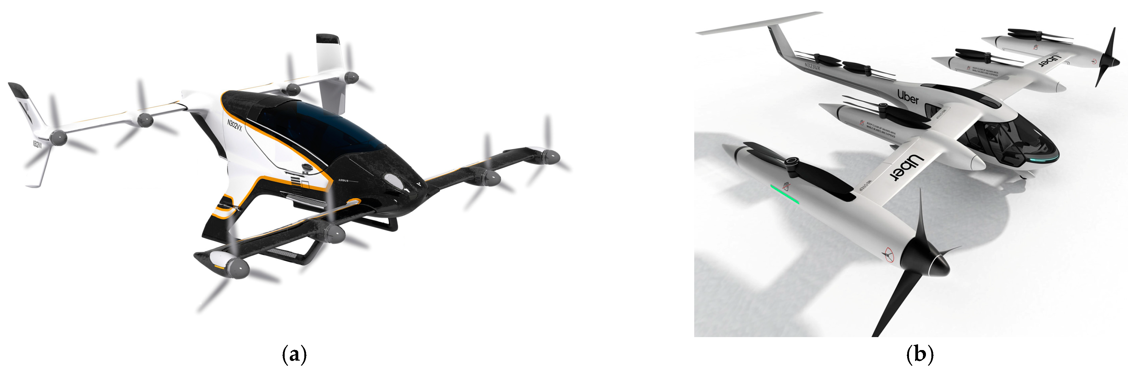
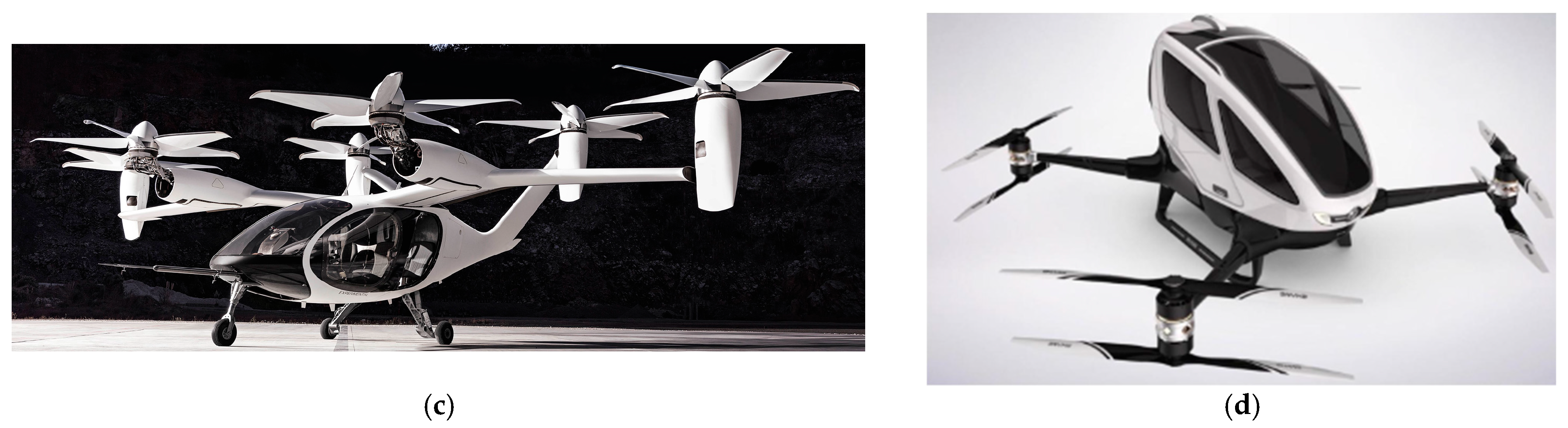
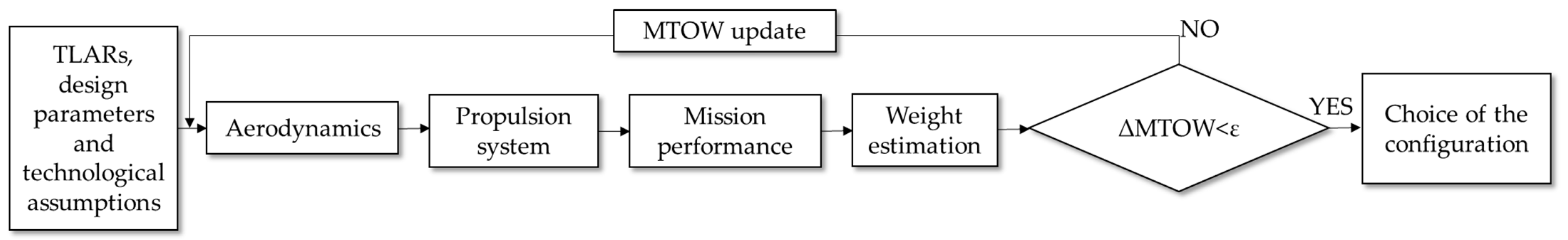
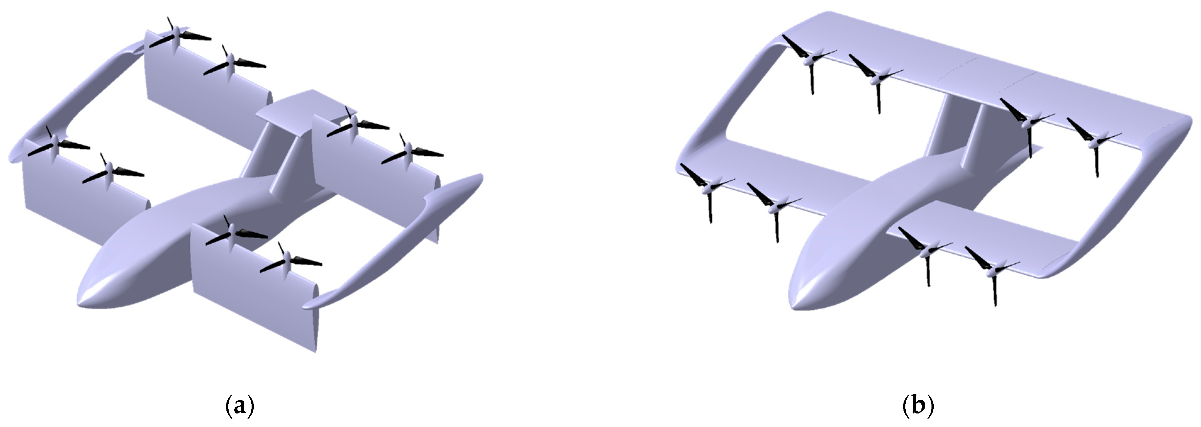
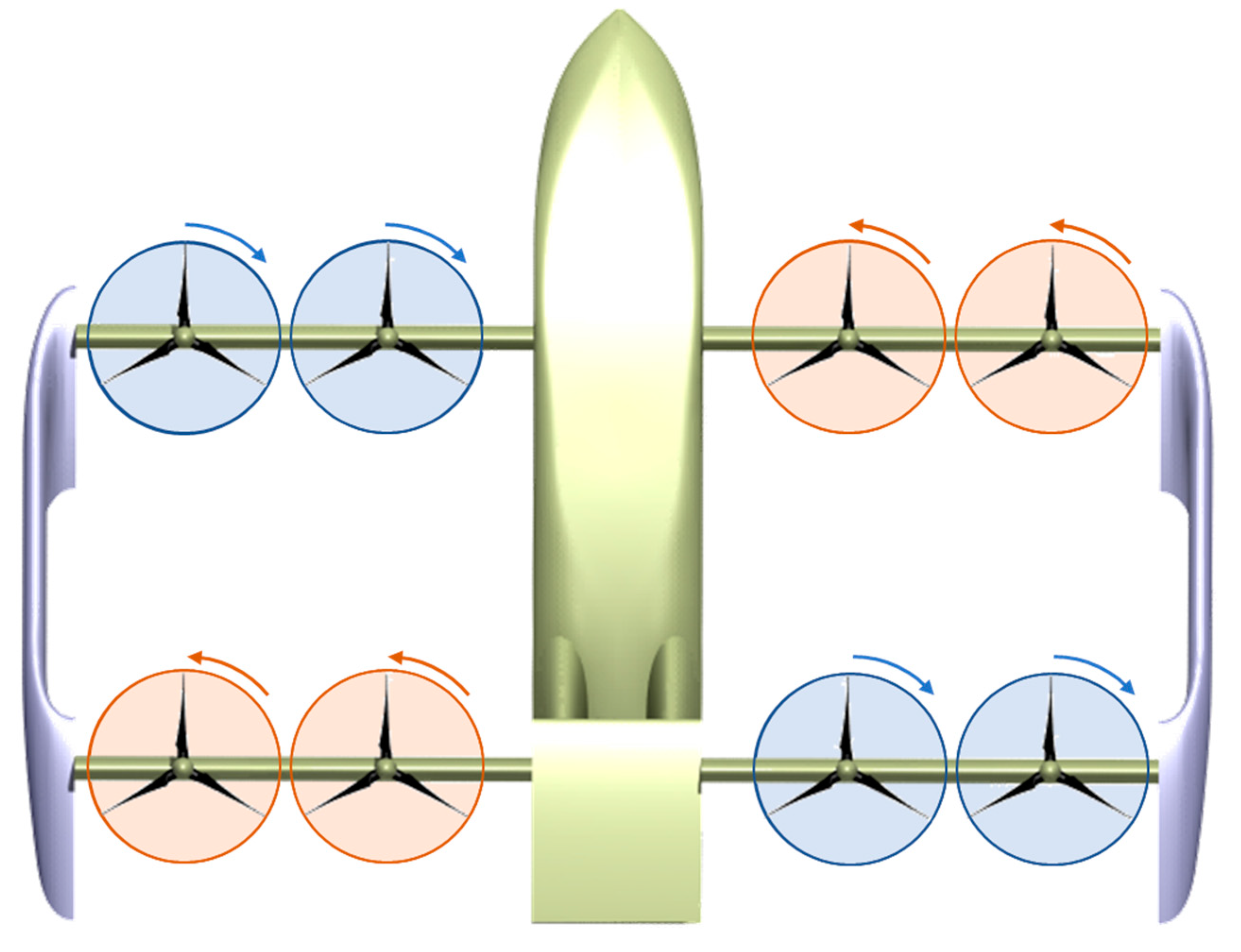
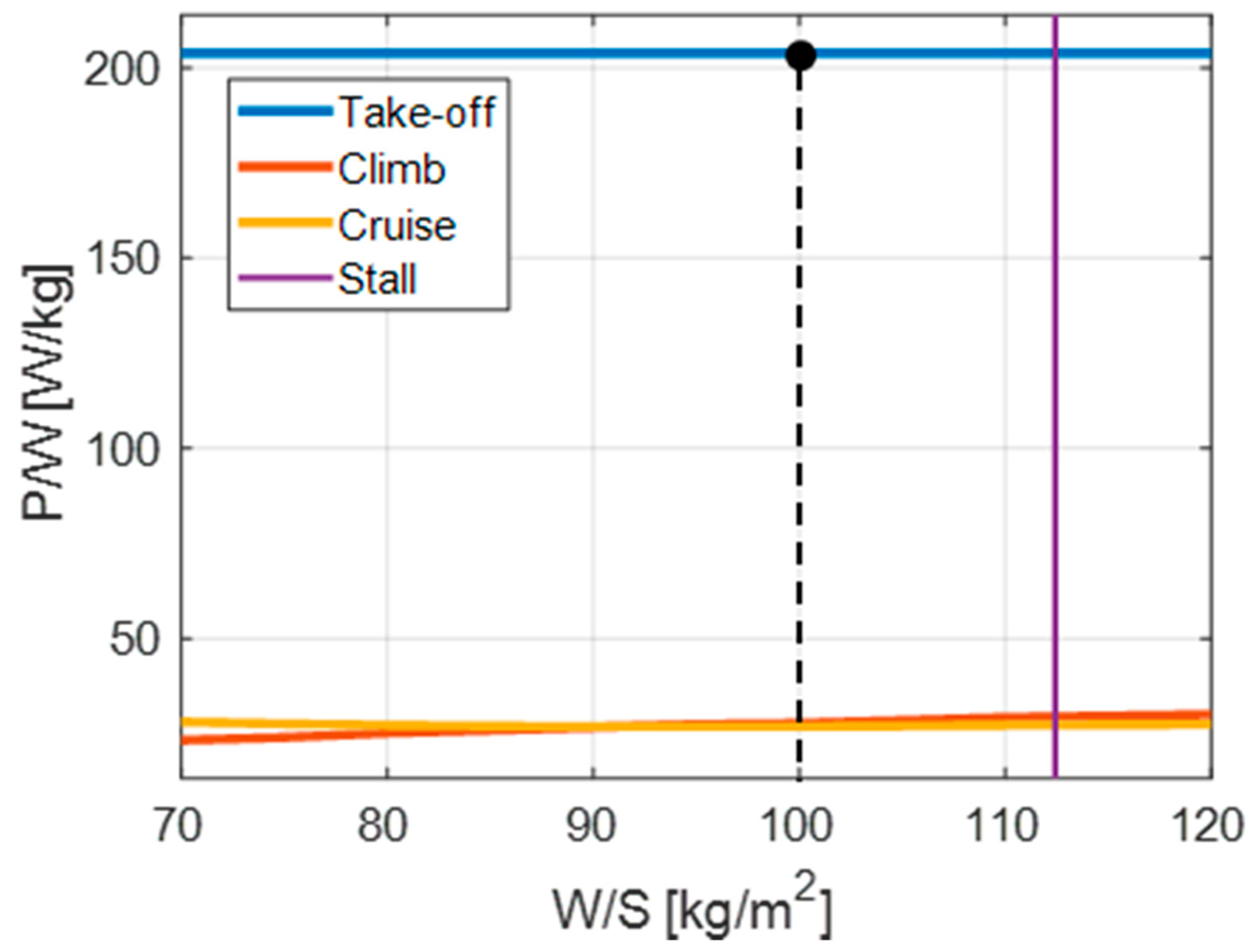
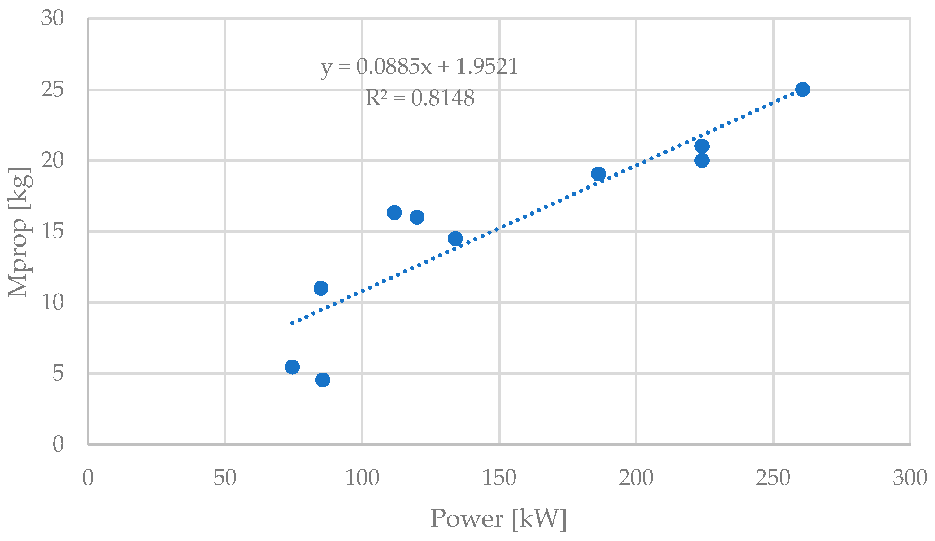
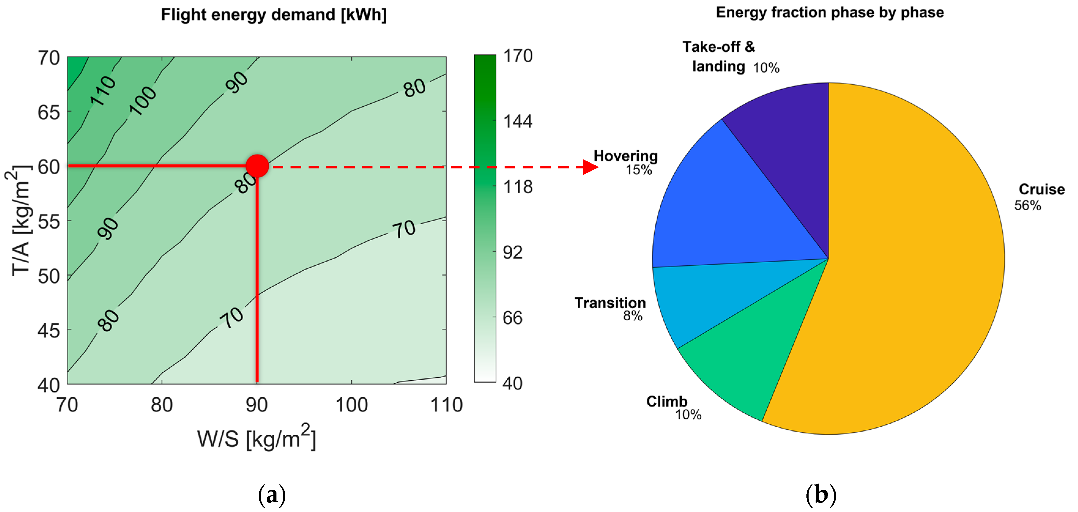
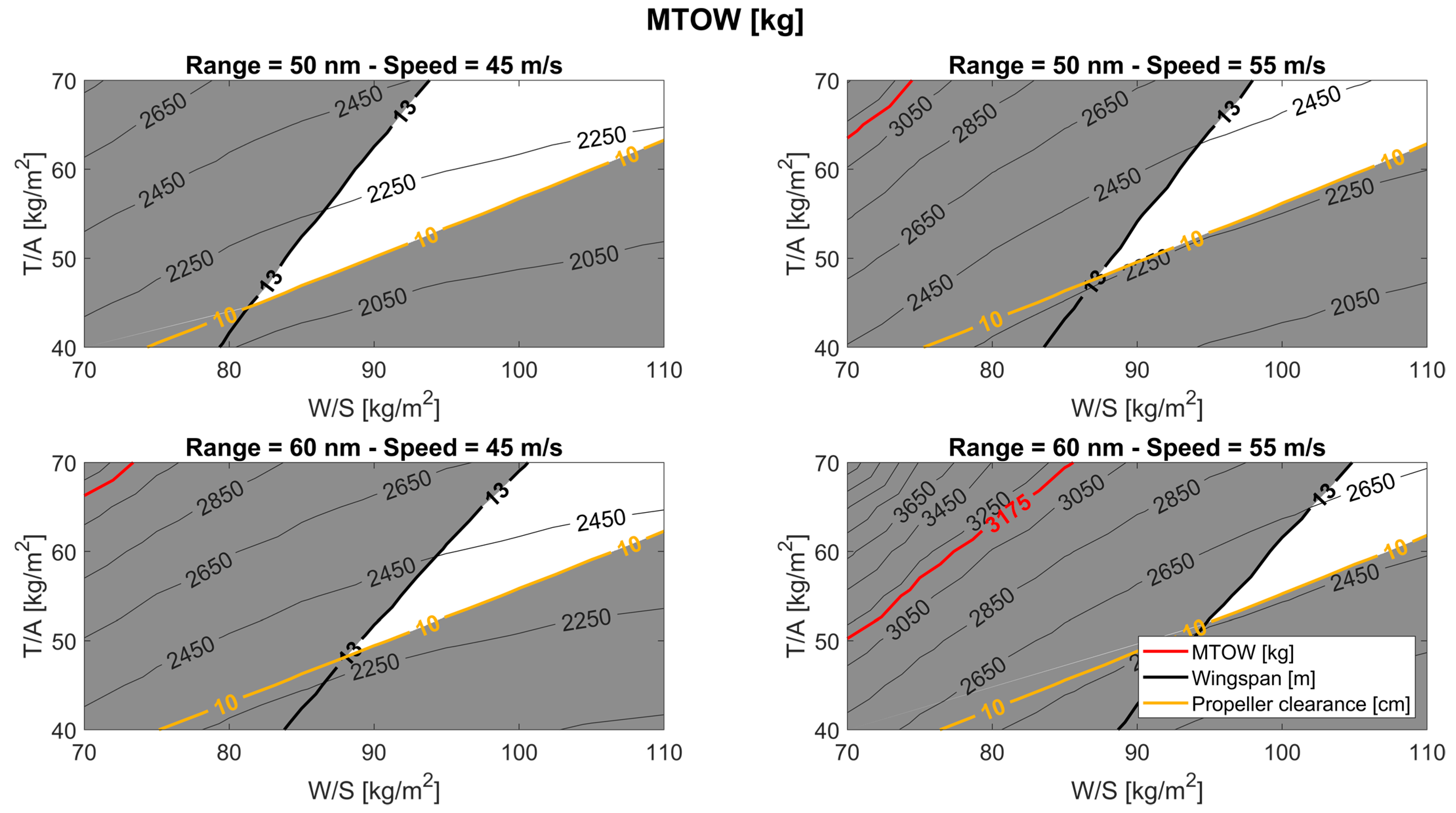
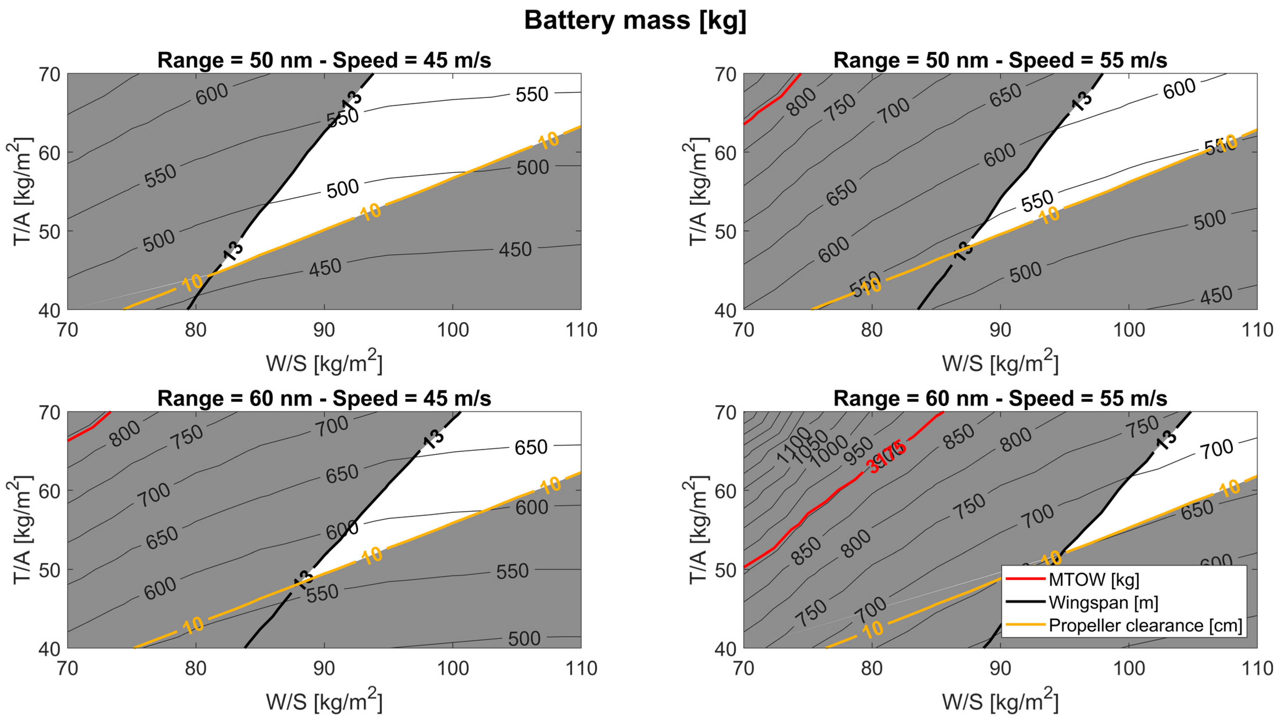
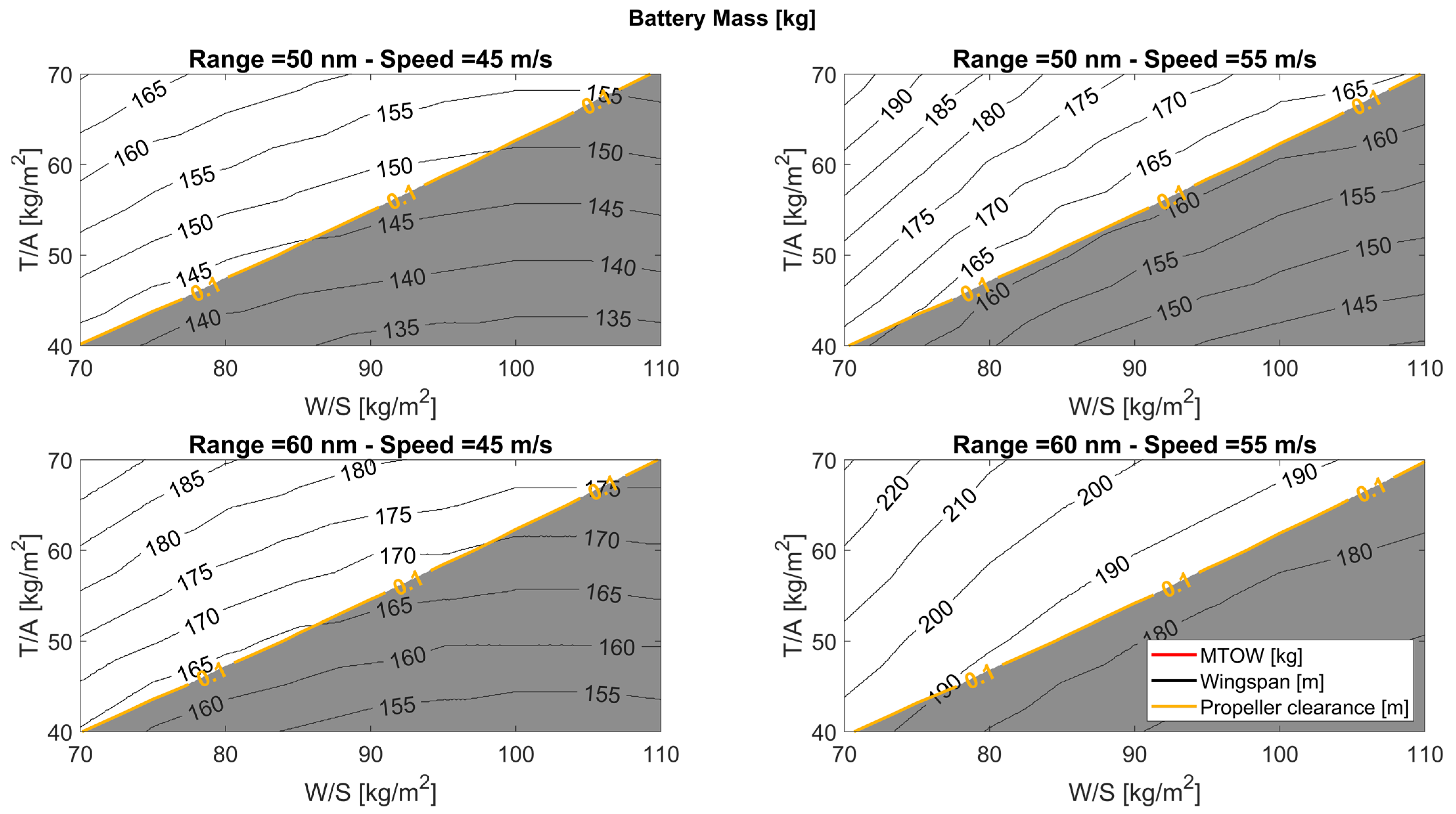
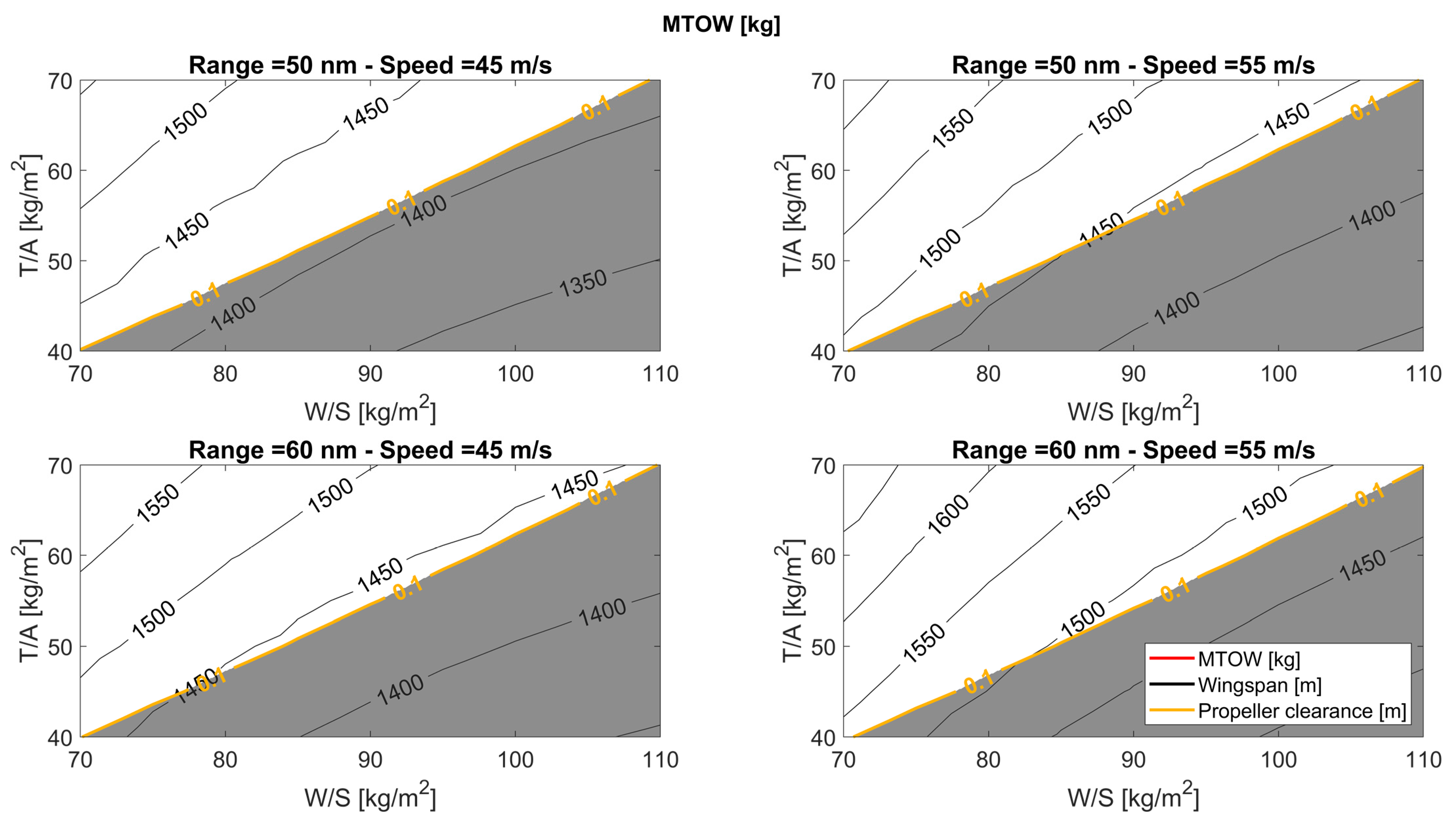
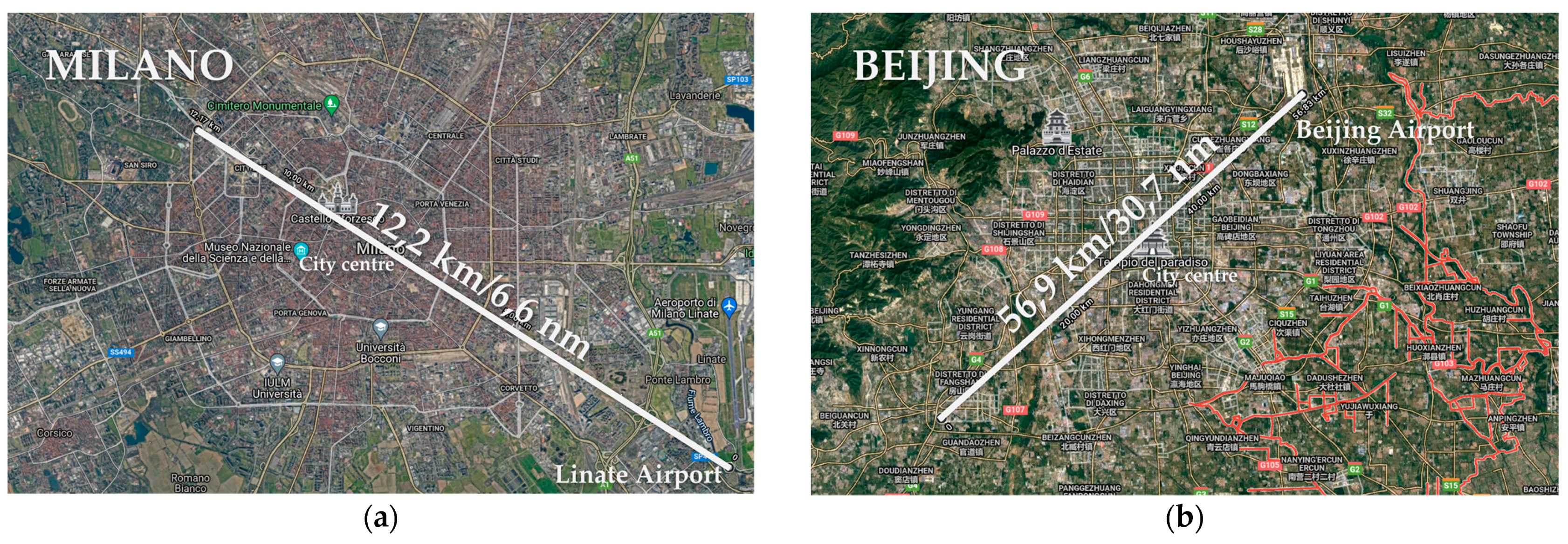
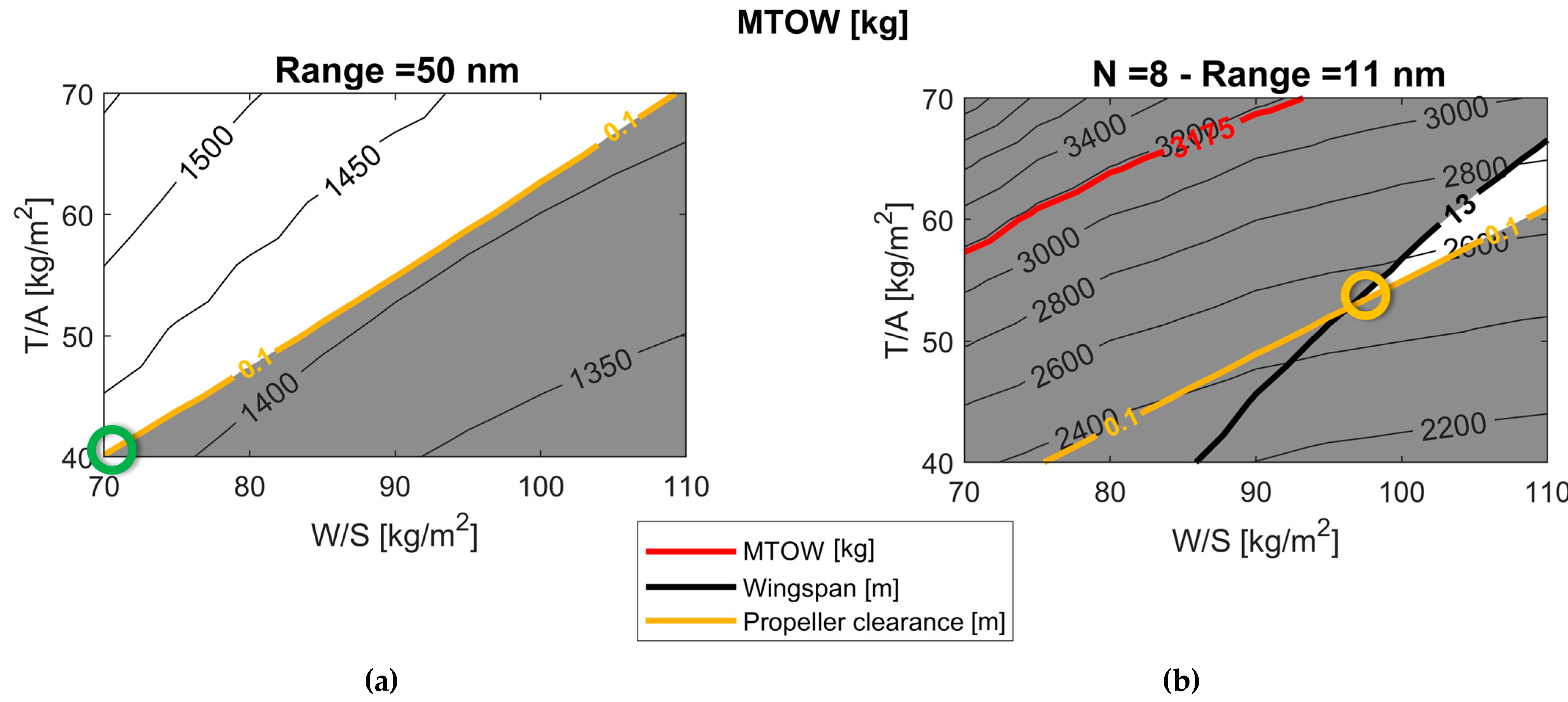
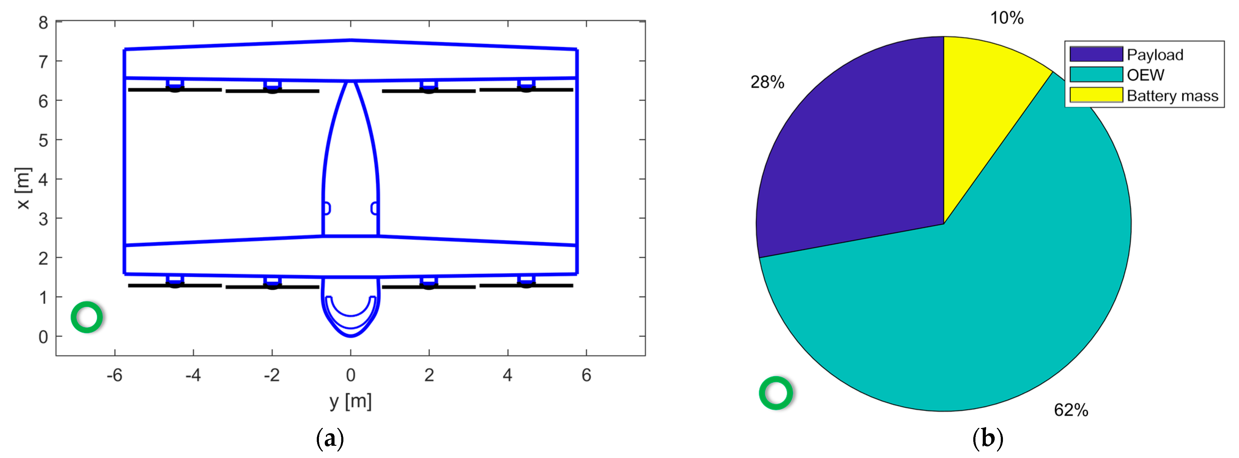
Table 1.
Main advantages and drawbacks of different e-VTOL aircraft types.
| Aircraft Type | Power Consumption in Cruise | Power Consumption in Hovering | Complexity | Noise in Hovering | Range and Speed | Internal Comfort |
|---|---|---|---|---|---|---|
| Lift+Cruise | Baseline | Baseline | Baseline | Baseline | Baseline | Baseline |
| Multi-rotor | Higher [24] | Lower [24] | Lower [24] | Lower [24] | Lower [24,30] | Lower |
| Tilt-wing/rotor | Lower [30] | Higher [24] | Higher [24] | Higher [24] | Higher [24,30] | Higher |
Table 2.
Main information of the conceptual design methodologies described in [39,40,41,42,43,44,45,46,47,48].
| Reference | N. of Passengers | VTOL Type | Aerodynamic Model | Weight Model | Optimization | Noise Evaluation |
|---|---|---|---|---|---|---|
| [39] | 10 | Full-electric T-W | Semi-empirical formulation [49] | Take-off Weight Build-up method [49] | Yes | No |
| [40] | 2 | Full-electric T-R | VLM and CFD | Semi-empirical formulation not stated | Yes | No |
| [41] | 2–10 | Full-electric H | Semi-empirical formulation [50] | Component weight build-up method [50] | No | No |
| [42] | 2–10 | Full-electric H, M-R, T-R and L + C | Semi-empirical formulation [49,51] | Take-off Weight Build-up method [52,53] | No | No |
| [43] | 4 | Full-electric L + C | Semi-empirical formulation [54] | Take-off Weight Build-up method [52] | No | No |
| [44] | 3 | Full-electric H, T-W, T-R and L + C | No computed, assumption on aerodynamic efficiency | Take-off Weight Build-up method [49] | Yes | Yes |
| [45] | 2/6 | Hybrid-electric T-W | CFD | Take-off Weight Build-up method [49] | No | No |
| [46] | 3 | Hybrid-electric tube-and-wing | JVL [46] | Component weight build-up method | Yes | No |
| [47] | 1/6/15 | Hybrid-electric M-R, H and T-W | Semi-empirical formulation | Detailed mass breakdown | Yes | No |
| [48] | 6 | Hybrid-electric and full-electric M-R, H and L + C | Semi-empirical formulation | Detailed mass breakdown | Yes | No |
Table 3.
TLARs for UAM.
| Number of Passengers (Npax) | Vary from 2 to 6 |
|---|---|
| Range | 50–60 nm |
| Cruise speed (VCR) | 45–55 m/s |
| Cruise height | 500 m Above Ground Level (AGL) |
| Diversion length | 5 nm |
Table 4.
Assumption for the design mission of the TiltOne.
| Phase | Name | Assumptions |
| 1–2 | Take-off | Maximum power for 30 s |
| 2–3 | Hovering | Hovering for 30 s at 100 m AGL |
| 3–4 | Transition | Uniform horizontal acceleration from 0 m/s to climb speed |
| 4–5 | Climb | Constant lift coefficient and RoC |
| 5–6 | Cruise | Constant speed and height AGL |
| 6–7 | Descent | Constant lift coefficient and RoD |
| 7–8 | Transition | Uniform horizontal deceleration from descent speed to 0 m/s |
| 8–9 | Hovering | Hovering for 30 s at 100 m AGL |
| 9–10 | Transition | Uniform horizontal acceleration from 0 m/s to climb speed |
| 10–11 | ClimbDiv | Constant lift coefficient and RoD |
| 11–12 | CruiseDiv | Constant speed and height AGL |
| 12–13 | DescentDiv | Constant lift coefficient and RoD |
| 13–14 | TransitionDiv | Uniform horizontal deceleration from descent speed to 0 m/s |
| 14–15 | HoveringDiv | Hovering for 30 s at 100 m AGL |
| 15–16 | Landing | 80% of requested power in hovering |
| Design mission | ||
 | ||
Table 5.
Comparison with the two-passenger configuration of the reference paper [45].
Table 5.
Comparison with the two-passenger configuration of the reference paper [45].
| Aircraft | Requirements and Assumptions | Polar Curves | |||
|---|---|---|---|---|---|
 Architecture: wing-tail VTOL type: tilt-wing N. of seats: 2 | Range [km] | 100 |  | ||
| Mpay [kg] | 200 | ||||
| P/W [W/kg] | 284 | ||||
| W/S [kg/m2] | 126 | ||||
| T/A [kg/m2] | 75 | ||||
| OUTPUT | Computed | Ref. | Δ% | ||
| MTOW [kg] | 1200 | 1005 | +19% | ||
| Mbatt/MTOW | 24% | 28% | −4% | ||
| OEW/MTOW | 59.3% | 52% | +7.5% | ||
Table 6.
Comparison with the four-passenger configuration of the reference paper [45].
Table 6.
Comparison with the four-passenger configuration of the reference paper [45].
| Aircraft | Requirements and Assumptions | Polar Curves | |||
|---|---|---|---|---|---|
 Architecture: tandem wing VTOL type: tilt-wing N. of seats: 4 | Range [km] | 100 |  | ||
| Mpay [kg] | 400 | ||||
| P/W [W/kg] | 284 | ||||
| W/S [kg/m2] | 126 | ||||
| T/A [kg/m2] | 75 | ||||
| OUTPUT | Computed | Ref. | Δ% | ||
| MTOW [kg] | 1877 | 1768 | +6% | ||
| Mbatt/MTOW | 24% | 27% | −3% | ||
| OEW/MTOW | 55% | 50% | +5% | ||
Table 7.
Comparison with the six-passenger configuration of the reference paper [45].
Table 7.
Comparison with the six-passenger configuration of the reference paper [45].
| Aircraft | Requirements and Assumptions | Polar Curves | |||
|---|---|---|---|---|---|
 Architecture: tandem + tail VTOL type: tilt-wing N. of seats: 6 | Range [km] | 100 |  | ||
| Mpay [kg] | 600 | ||||
| P/W [W/kg] | 284 | ||||
| W/S [kg/m2] | 126 | ||||
| T/A [kg/m2] | 75 | ||||
| OUTPUT | Computed | Ref. | Δ% | ||
| MTOW [kg] | 2685 | 2534 | +6% | ||
| Mbatt/MTOW | 24% | 27% | −3% | ||
| OEW/MTOW | 54% | 49% | +5% | ||
Table 8.
Main Top Level Aircraft requirements for the box-wing tilt-wing conceptual design.
| Type of Propulsion | Full-Electric |
|---|---|
| N° of motors/propellers | 8 |
| N° of passengers | 4 |
| Design range | [50,60] nm |
| Cruise speed | [45,55] m/s |
| Cruise height (AGL) | 500 m |
| Diversion range | 5 nm |
Table 9.
Main constraints for the box-wing tilt-wing conceptual design.
| MTOW | <3175 kg, according to [32] |
| Wingspan | <13 m, according to [38] |
| Clearance between propellers | >0.1 m |
Table 10.
Current technological parameters for electric machines and components, and batteries.
| Electric Motor Power Density [45,68,86,87] | 5 kW/kg |
| Battery Energy Density @ pack level [45] | 250 Wh/kg |
| Battery Management System Power Density [68] | 20 kW/kg |
| ESC Power Density [87] | 20 kW/kg |
| Cable power density [78] | 10 g/(m kW) |
| Wire efficiency [68] | 0.99 |
| ESC efficiency [88] | 0.95 |
| Battery efficiency [89] | 0.92 |
| Motor efficiency [89,90] | 0.92 |
Table 11.
Main assumptions of the design mission of the TiltOne.
| Phase (See Table 4) | Name | Assumption |
|---|---|---|
| 1–2 | Take-off | Maximum power for 30 s |
| 2–3 | Hovering | Hovering for 30 s at 100 m AGL |
| 3–4 | Transition | Uniform horizontal acceleration from 0 m/s to climb speed |
| 4–5 | Climb | Constant CL (Equation (8)) and RoC = 500 ft/min |
| 5–6 | Cruise | Constant speed (Table 8) @ 500 m AGL |
| 6–7 | Descent | CL of maximum efficiency and RoD = −500 ft/min |
| 7–8 | Transition | Uniform horizontal deceleration from descent speed to 0 m/s |
| 8–9 | Hovering | Hovering for 30 s at 100 m AGL |
| 15–16 | Landing | 80% of requested power in hovering |
Table 12.
Future (2035) and current technological parameters for powertrain components.
| Future (2035) | Current (2021) | |
|---|---|---|
| Electric Motor Power Density [45,85,89] | 10 kW/kg | 5 kW/kg |
| Battery Energy Density @ pack level [45,85] | 500 Wh/kg | 250 Wh/kg |
| Battery Management System Power Density [88] | 63 kW/kg | 20 kW/kg |
| ESC Power Density [88] | 63 kW/kg | 20 kW/kg |
| Cable power density [78] | 10 g/(m kW) | 10 g/(m kW) |
| Wire efficiency [90] | 0.99 | 0.99 |
| Battery efficiency [89] | 0.95 | 0.92 |
| ESC efficiency [88] | 0.98 | 0.95 |
| Motor efficiency [88] | 0.95 | 0.92 |
Table 13.
Comparison of two TiltOne configurations with same T/A (55 kg/m2) and W/S (90 kg/m2) and different technological levels.
Table 13.
Comparison of two TiltOne configurations with same T/A (55 kg/m2) and W/S (90 kg/m2) and different technological levels.
| Current | Future | Δ% | |
|---|---|---|---|
| Cruise speed | 45 m/s | 45 m/s | = |
| Range | 50 nm | 50 nm | = |
| Payload | 400 kg (4 pax) | 400 kg (4 pax) | = |
| W/S | 90 kg/m2 | 90 kg/m2 | = |
| T/A | 55 kg/m2 | 55 kg/m2 | = |
| MTOW | 2212 kg | 1408 kg | −36% |
| Battery mass | 500 kg | 146 kg | −71% |
| Wingspan | 12.6 m | 10.1 m | −20% |
| Propeller diameter | 2.53 m | 2.02 m | −20% |
| Electric motor power | 8 × 82.6 kW | 8 × 52.6 kW | −36% |
| Installed specific power | 299 W/kg | 299 W/kg | = |
Table 14.
Main performance data of the TiltOne configuration for single mission case.
 Single Mission Single Mission | |
|---|---|
| N. of passengers | 4 |
| W/S [kg/m2] | 70 |
| T/A [kg/m2] | 40 |
| Wingspan [m] | 11.5 |
| MTOW [kg] | 1427 |
| Battery mass [kg] | 142 |
| Cruise speed [m/s] | 45 |
| Harmonic range [nm] | 50 |
| Maximum hovering time [min] | 13.5 |
| Missions @ 7 nm | 2 |
| Missions @ 11 nm | 2 |
| Missions @ 15 nm | 2 |
| Missions @ 25 nm | 1 |
| Missions @ 35 nm | 1 |
| Missions @ 50 nm | 1 |
Table 15.
Main performance data of the TiltOne configuration for multi mission case.
 Multi Mission Multi Mission | |
|---|---|
| N. of passengers | 4 |
| W/S [kg/m2] | 98 |
| T/A [kg/m2] | 54 |
| Wingspan [m] | 12.9 |
| MTOW [kg] | 2512 |
| Battery mass [kg] | 858 |
| Cruise speed [m/s] | 45 |
| Harmonic range [nm] | 263 |
| Maximum hovering time [min] | 39.9 |
| Missions @ 7 nm | 8 |
| Missions @ 11 nm | 8 |
| Missions @ 15 nm | 7 |
| Missions @ 25 nm | 5 |
| Missions @ 35 nm | 4 |
| Missions @ 50 nm | 3 |
Publisher’s Note: MDPI stays neutral with regard to jurisdictional claims in published maps and institutional affiliations. |
© 2021 by the authors. Licensee MDPI, Basel, Switzerland. This article is an open access article distributed under the terms and conditions of the Creative Commons Attribution (CC BY) license (https://creativecommons.org/licenses/by/4.0/).
Share and Cite
MDPI and ACS Style
Palaia, G.; Abu Salem, K.; Cipolla, V.; Binante, V.; Zanetti, D. A Conceptual Design Methodology for e-VTOL Aircraft for Urban Air Mobility. Appl. Sci. 2021, 11, 10815. https://0-doi-org.brum.beds.ac.uk/10.3390/app112210815
AMA Style
Palaia G, Abu Salem K, Cipolla V, Binante V, Zanetti D. A Conceptual Design Methodology for e-VTOL Aircraft for Urban Air Mobility. Applied Sciences. 2021; 11(22):10815. https://0-doi-org.brum.beds.ac.uk/10.3390/app112210815
Chicago/Turabian StylePalaia, Giuseppe, Karim Abu Salem, Vittorio Cipolla, Vincenzo Binante, and Davide Zanetti. 2021. "A Conceptual Design Methodology for e-VTOL Aircraft for Urban Air Mobility" Applied Sciences 11, no. 22: 10815. https://0-doi-org.brum.beds.ac.uk/10.3390/app112210815
Note that from the first issue of 2016, this journal uses article numbers instead of page numbers. See further details here.