
Low-Phase-Noise Oscillator Using a High-QL Resonator with Split-Ring Structure and Open-Loaded T-Type Stub for a Tumor-Location-Tracking Sensor


Abstract
:
1. Introduction
2. Tumor-Tracking Oscillator and Sensor
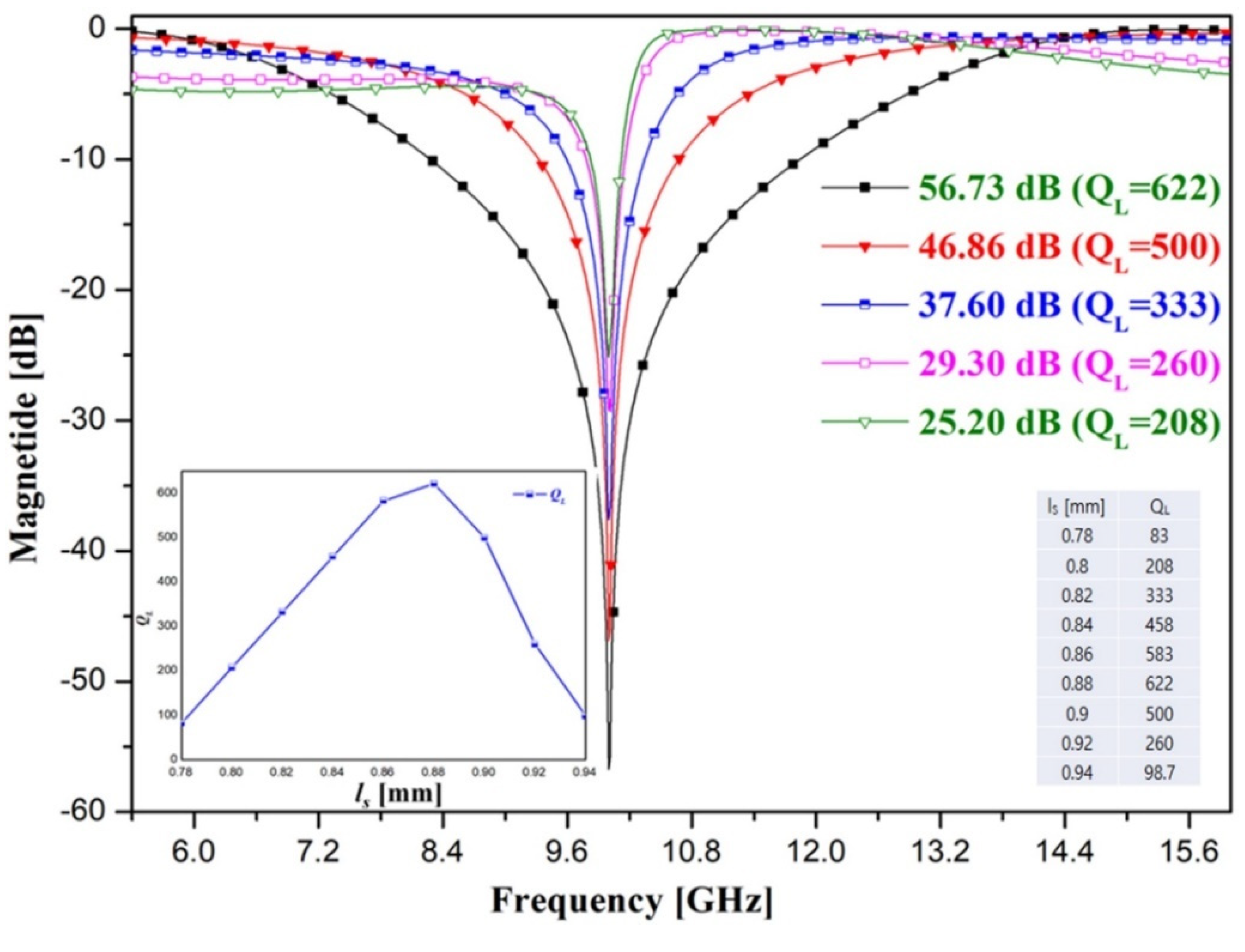
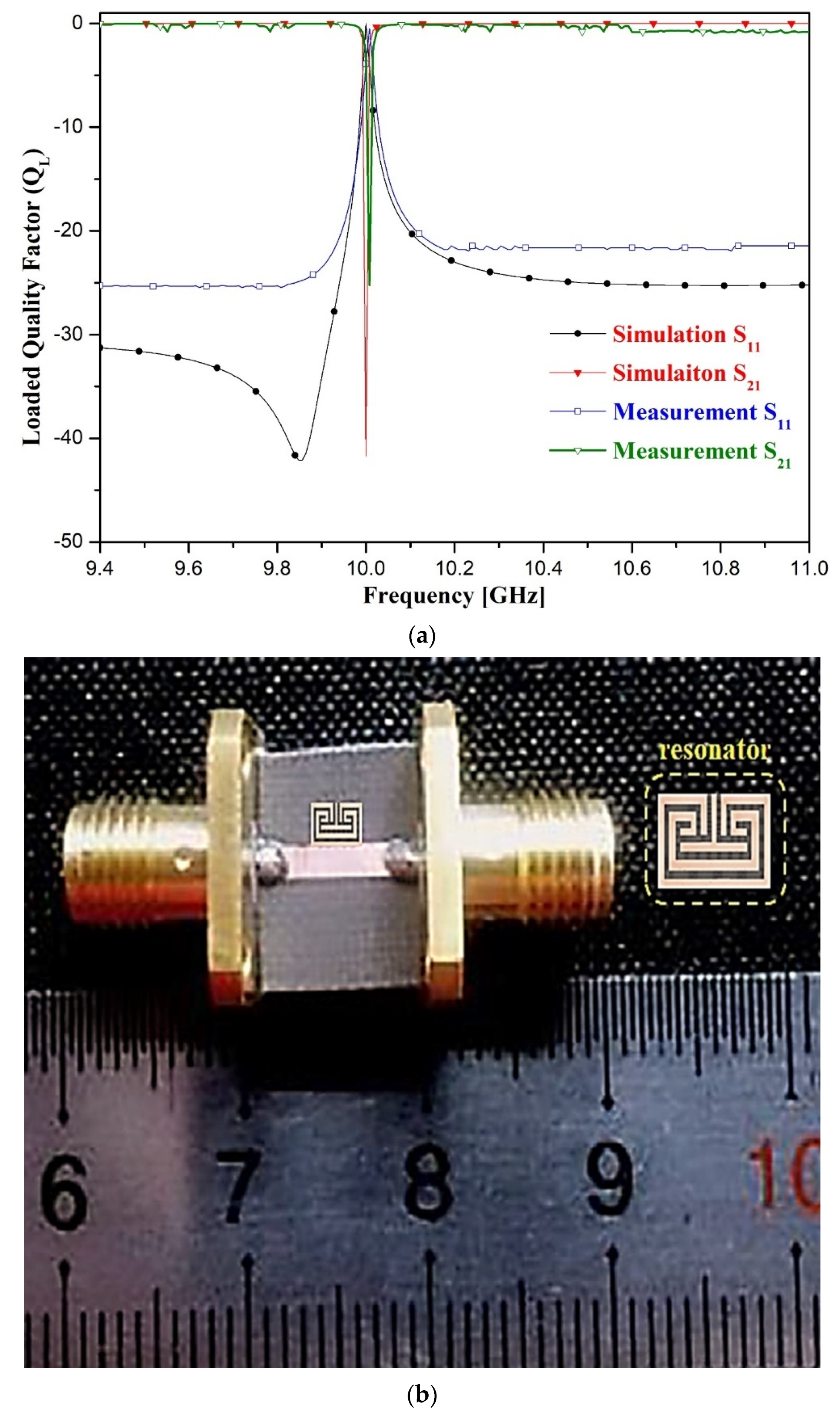
3. Design of a Resonator and Experimental Results
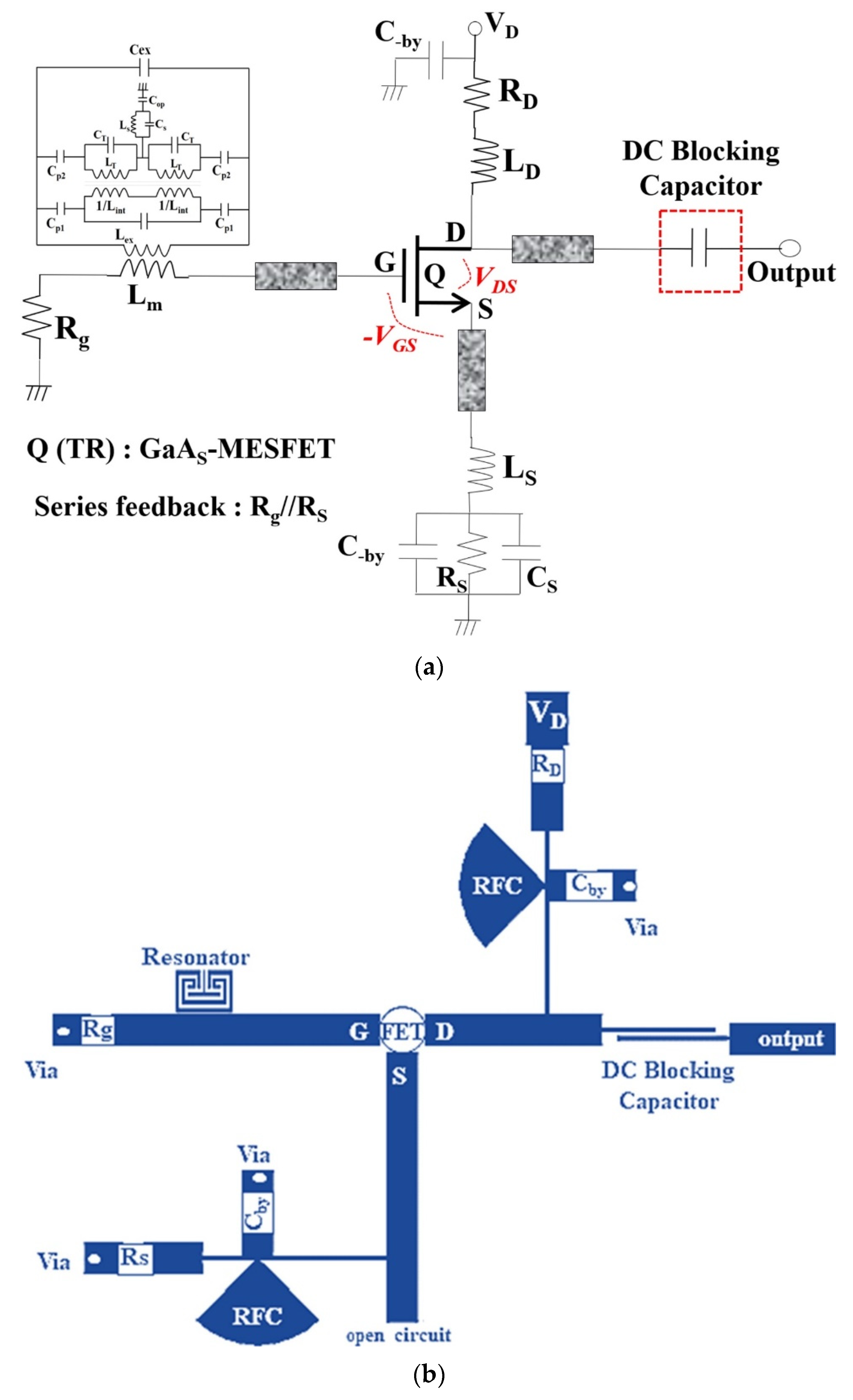
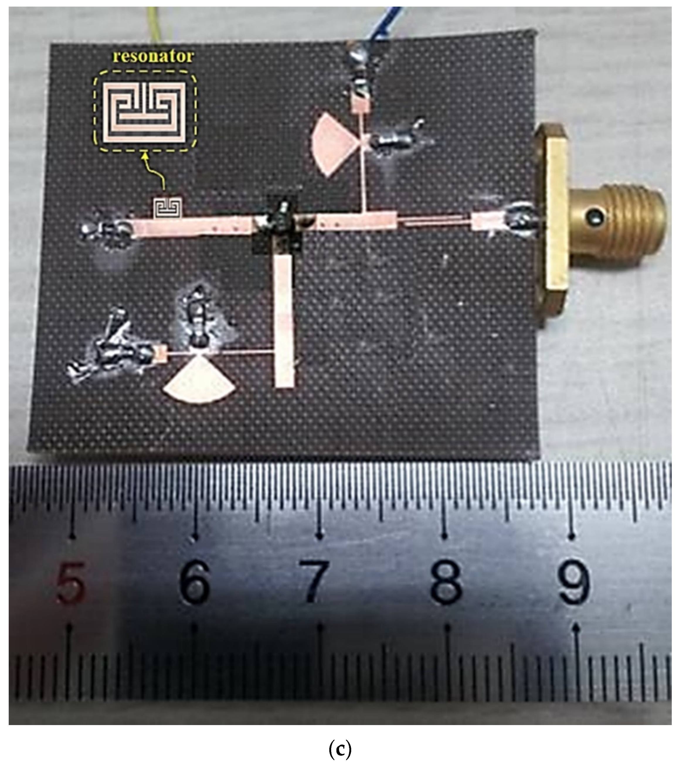
4. Oscillator Design and Measurement Results
5. Conclusions
Author Contributions
Funding
Institutional Review Board Statement
Informed Consent Statement
Data Availability Statement
Acknowledgments
Conflicts of Interest
References
- Lee, K.M.; Min, J.S.; Choi, W.J.; Ahn, J.W.; Yoon, S.W.; Kim, Y.J. An advanced RFID-based system to localize gastric and colon cancers during laparoscopic surgery. Surg. Endosc. 2021, 35, 139–147. [Google Scholar] [CrossRef]
- Mellal, I.; Fouzar, Y.; Oukaira, A.; Kengne, E.; Laklissassi, A. Improved thermal ablation of tumors using a real-time local data measurement system. Biomed. J. Sci. Tech. Res. (BJSTR) 2018, 11, 1–11. [Google Scholar] [CrossRef]
- Singha, R.; Singh, E.; Singh Nalwa, H. Inkjet printed nanomaterial based flexible radio frequency identification (RFID) tag sensors for the internet of nano things. RSC Adv. 2017, 7, 48597–48630. [Google Scholar] [CrossRef] [Green Version]
- Lee, H.J.; Lee, J.H.; Choi, S.; Jang, I.S. Asymmetric split-ring resonator-based biosensor for detection of label-free stress biomarkers. Appl. Phys. Lett. 2013, 103, 053702. [Google Scholar] [CrossRef]
- Lee, H.J.; Lee, H.S.; Yoo, K.H.; Yook, J.G. DNA sensing using split-ring resonator alone at microwave regime. J. Appl. Phys. 2010, 108, 014908. [Google Scholar] [CrossRef]
- Jang, C.; Lee, H.J.; Yook, J.G. Radio-frequency biosensors for real-time and continuous glucose detection. Sensors 2021, 21, 1843. [Google Scholar] [CrossRef] [PubMed]
- Abdul-Razzak, M.M.; Hardwick, B.A.; Hey-Shipton, G.L.; Matthews, P.A.; Monson, J.R.T.; Kester, R.C. Microwave thermography for medical applications. IEE Proc. 1987, 134 Pt A, 171–174. [Google Scholar] [CrossRef]
- Guardiola, M.; Buitrago, S.; Fernández-Esparrach, G.; O’Callaghan, J.M.; Romeu, J.; Cuatrecasas, M.; Córdova, H.; Ángel González Ballester, M.; Camara, O. Dielectric properties of colon polyps, cancer and normal mucosa: Ex vivo measurements from 0.5 to 20 GHz. Med. Phys. 2018, 45, 3768–3782. [Google Scholar] [CrossRef] [PubMed] [Green Version]
- Yoon, K.C.; Ahn, S.; Lee, J.C. A compact low-phase noise oscillator using π-network and complimentary μ-near zero metamaterial resonator. Microw. Opt. Technol. Lett. 2019, 61, 9–14. [Google Scholar] [CrossRef] [Green Version]
- Zhang, R.; Zhou, J.; Yu, Z.; Yang, B. A low phase noise feedback oscillator based on SIW bandpass response power divider. IEEE Microw. Wirel. Compon. Lett. 2018, 28, 153–155. [Google Scholar] [CrossRef]
- Lee, Y.T.; Lim, J.S.; Kim, C.S.; Ahn, D.; Nam, S. A compact-size microstrip spiral resonator and its applications to microwave oscillator. IEEE Microw. Wirel. Compon. Lett. 2002, 12, 375–377. [Google Scholar] [CrossRef]
- Michael Wu, C.T.; Poddar, A.K.; Rohde, U.L. Active complementary coupled resonator for low phase noise X-band oscillator. In Proceedings of the 2014 European Frequency and Time Forum (EFTF), Neuchatel, Switzerland, 23–26 June 2014. [Google Scholar] [CrossRef]
- Yang, Z.; Luo, B.; Dong, J.; Yang, T. X-band low phase noise loop oscillator with differential outputs. IEE Electron. Lett. 2015, 51, 1005–1007. [Google Scholar] [CrossRef]
- Xu, J.; Cui, Y.; Xu, Z.; Guo, J.; Qian, C.; Li, W. Low phase noise oscillator based on complementary split-ring resonators loaded quarter-mode circular SIW cavit. IEE Electron. Lett. 2011, 53, 933–935. [Google Scholar] [CrossRef]
- Liu, Z.; Xu, J.; Wang, W. Low phase noise oscillator stabilised by high quality factor AFSIW resonators. IEE Electron. Lett. 2018, 54, 1128–1130. [Google Scholar] [CrossRef]
- Cho, S.J.; Kim, N.Y. Comparative analysis of the electrical properties of a low noise oscillator embedded in a symmetrical square open-loop with loaded stub resonator. Microw. Opt. Technol. Lett. 2014, 56, 2132–2136. [Google Scholar] [CrossRef]
- Wang, X.; Zhu, X.W. An X-band push-push oscillator with parallel feedback configuration designed by microstrip balanced bandpass filter. Int. J. RF Microw. Comput.-Aided Eng. 2019, 29, e21663. [Google Scholar] [CrossRef]
- Aldhaeebi, M.A.; Alzoubi, K.; Almoneef, T.S.; Bamatraf, S.M.; Attia, H.; Ramah, O.M. Review of Microwaves Techniques for Breast Cancer Detection. Sensors 2020, 20, 2390. [Google Scholar] [CrossRef] [PubMed] [Green Version]
- Wang, L. Microwave sensors for breast cancer detection. Sensors 2018, 18, 655. [Google Scholar] [CrossRef] [Green Version]
- Cai, Z.; Tang, X.; Zhang, T.; Yang, Y. An X-band low phase noise oscillator with high harmonic suppression using SIW quarter-wavelength resonator. In Proceedings of the 2018 IEEE/MTT-S International Microwave Symposium—IMS, Philadelphia, PA, USA, 10–15 June 2018. [Google Scholar] [CrossRef]
- Nimehvari Varcheh, H.; Rezaei, P. Low phase-noise X-band oscillator based on elliptic filter and branchline coupler. IET Microw. Antennas Propag. 2019, 13, 888–897. [Google Scholar] [CrossRef]
- Mongia, R.; Bahl, I.; Bhartia, P. Rf and Microwave Coupled-Line Circuit; Artech House: London, UK, 1999. [Google Scholar]
- Abduljabar, A.A.; Rowe, D.J.; Porch, A.; Barrow, D.A. Novel microwave microfluidic sensor using a microstrip split-ring resonator. IEEE Trans. Microw. Theory Tech. 2014, 62, 679–688. [Google Scholar] [CrossRef]
- Yoon, K.; Kim, K. Design of dual ultra–wideband band–pass filter using stepped impedance resonator λg/4 short stubs and T–shaped band-stop filter. Electronics 2021, 10, 1951. [Google Scholar] [CrossRef]
- Berbeco, R.I.; Mostafavi, H.; Sharp, G.C.; Jiang, S.C. Towards fluoroscopic respiratory gating for lung tumours without radiopaque markers. Phys. Med. Biol. 2005, 50, 4481–4490. [Google Scholar] [CrossRef]
- Deng, S. Effects of open stubs associated with plated through-hole vias in backpanel designs. Int. Symp. Electromagn. Compat. 2004, 3, 1017–1022. [Google Scholar] [CrossRef]
- Kushta, T.; Narita, K.; Kaneko, T.; Saeki, T.; Tohya, H. Resonance stub effect in a transition from a through via hole to a stripline in multilayer PCBs. IEEE Microw. Wirel. Compon. Lett. 2003, 13, 169–171. [Google Scholar] [CrossRef]


| Reference | Resonant Frequency (GHz) | QL | Detection Tissue |
|---|---|---|---|
| [4] | 11.2 | 100 | cortisol |
| [5] | 12.3 | 50 | DNA |
| [6] | 7.54 | 130 | glucose |
| Parameter | Value | Unit | Parameter | Value | Unit | ||
|---|---|---|---|---|---|---|---|
| Capacitance | Cex | 1.86 | pF | Characteristic impedance | Zex | 127 | Ω |
| Cin,m,n | 9.72 | pF | Zin,m,n | 200 | Ω | ||
| Cp1 | 8.81 | pF | Zp1 | 41.7 | Ω | ||
| Cp2 | 9.36 | pF | Zp2 | 81.2 | Ω | ||
| CS | 6.43 | μF | Zop | 4.17 | Ω | ||
| Cop | 1.20 | mF | ZT | 86.6 | Ω | ||
| Inductance | Lex | 2.208 | H | ZS | 75.0 | Ω | |
| Lin,m,n | 4.43 | H | Electrical length | θTH | 49.59° | deg | |
| LT | 11.0 | mH | θTV | 27.27° | deg | ||
| LS | 5.02 | H | θex1 | 16.6° | deg | ||
| Physical length | lTH | 3.00 | mm | θex2 | 8.59° | deg | |
| lTV | 1.65 | mm | θin1 | 32.8° | deg | ||
| lex1 | 1.00 | mm | θin2 | 11.2° | deg | ||
| lex2 | 0.52 | mm | θin3 | 6.72° | deg | ||
| lin1 | 2.05 | mm | θin4 | 2.08° | deg | ||
| lin2 | 0.70 | mm | θin5 | 4.64° | deg | ||
| lin3 | 0.42 | mm | θT | 30.0° | deg | ||
| lin4 | 0.13 | mm | θS | 45.0° | deg | ||
| lin5 | 0.29 | mm | Physical width | wex | 0.19 | mm | |
| lt | 0.84 | mm | win,m,n | 0.19 | mm | ||
| ls | 0.86 | mm | >wT | 0.14 | mm | ||
| Gap size | gex | 0.13 | mm | wS | 0.13 | mm | |
| gin | 0.13 | mm | Phase constant | β1 | 2.42 | rad/m | |
| β2 | 2.493 | rad/m | |||||
| Reference | Frequency (GHz) | Phase Noise (dBc/Hz) at 100 kHz | Output Power (dBm) | QL | FOM (dBc/Hz) at 100 kHz |
|---|---|---|---|---|---|
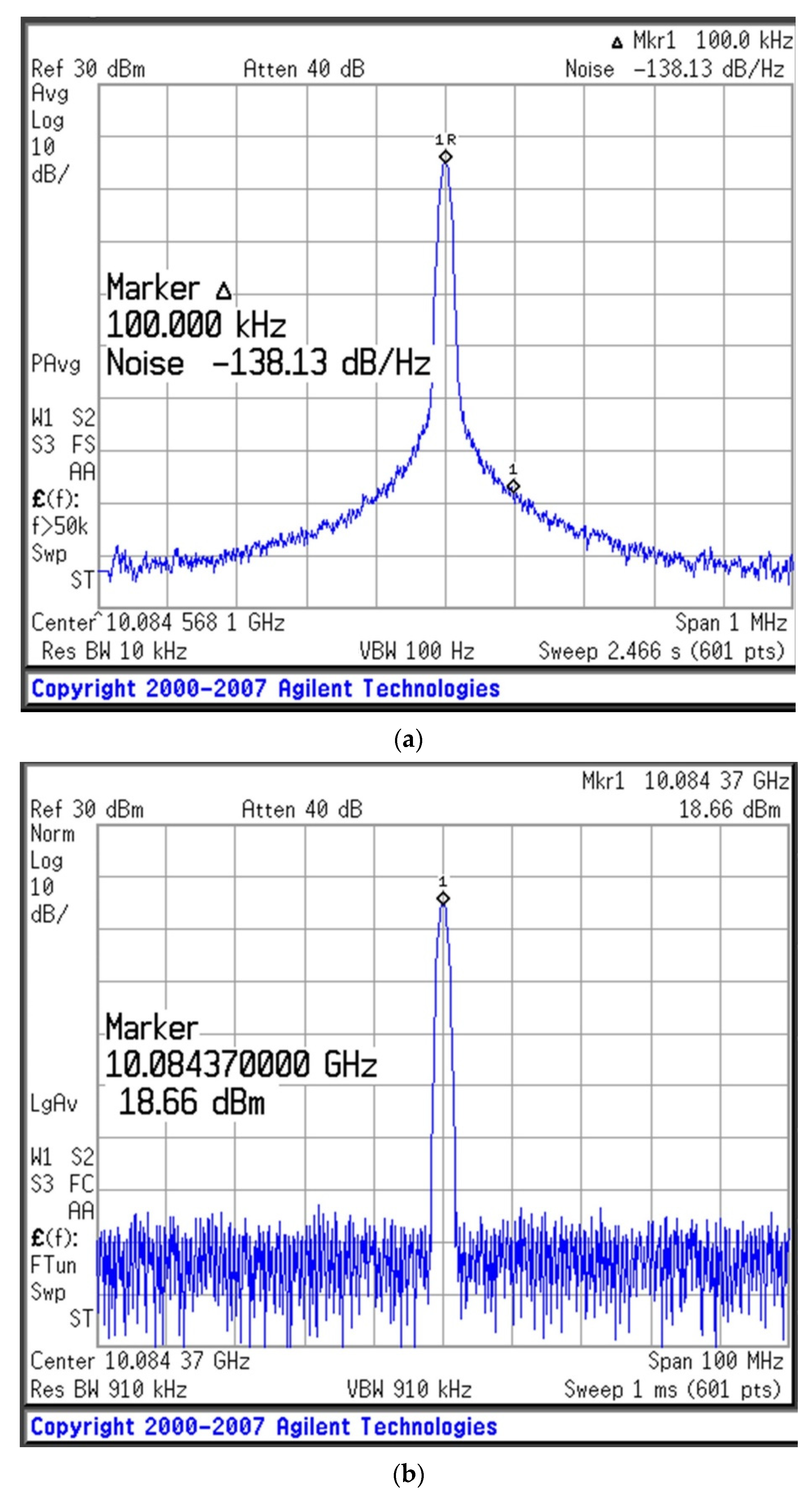
| This work | 10.08 | −138.13 | 18.66 | 632 | −195.7 |
| [10] | 10.98 | −121.6 | 1.800 | − | −182.3 |
| [11] | 10.00 | −95.40 | 10.16 | 190 | −135.3 |
| [12] | 9.883 | −97.60 | 3.020 | 260 | −182.2 |
| [13] | 9.010 | −104.3 | 1.800 | 104 | −104.3 |
| [14] | 10.11 | −108.7 | 4.600 | 520 | −172.2 |
| [15] | 9.850 | −124.8 | 3.600 | 243 | −189.1 |
| [16] | 6.200 | −104.62 | 14.68 | 430 | −156.2 |
| [17] | 9.960 | −128.30 (@ 1 MHz) | 8.570 | 66.7 | −193.2 (@ 1 MHz) |
| [20] | 8.080 | −109.94 | 2.140 | − | −174.2 |
| [21] | 8.172 | −112.0 | 4.000 | − | −174.2 |
Publisher’s Note: MDPI stays neutral with regard to jurisdictional claims in published maps and institutional affiliations. |
© 2021 by the authors. Licensee MDPI, Basel, Switzerland. This article is an open access article distributed under the terms and conditions of the Creative Commons Attribution (CC BY) license (https://creativecommons.org/licenses/by/4.0/).
Share and Cite
Yoon, K.-C.; Kim, K.-G.; Chung, J.-W.; Kim, B.-S. Low-Phase-Noise Oscillator Using a High-QL Resonator with Split-Ring Structure and Open-Loaded T-Type Stub for a Tumor-Location-Tracking Sensor. Appl. Sci. 2021, 11, 11550. https://0-doi-org.brum.beds.ac.uk/10.3390/app112311550
Yoon K-C, Kim K-G, Chung J-W, Kim B-S. Low-Phase-Noise Oscillator Using a High-QL Resonator with Split-Ring Structure and Open-Loaded T-Type Stub for a Tumor-Location-Tracking Sensor. Applied Sciences. 2021; 11(23):11550. https://0-doi-org.brum.beds.ac.uk/10.3390/app112311550
Chicago/Turabian StyleYoon, Ki-Cheol, Kwang-Gi Kim, Jun-Won Chung, and Byeong-Soo Kim. 2021. "Low-Phase-Noise Oscillator Using a High-QL Resonator with Split-Ring Structure and Open-Loaded T-Type Stub for a Tumor-Location-Tracking Sensor" Applied Sciences 11, no. 23: 11550. https://0-doi-org.brum.beds.ac.uk/10.3390/app112311550