
Carbon Nanotube-Based Composite Filaments for 3D Printing of Structural and Conductive Elements


Micro- and Nano-Technology Division, Institute of Metrology and Biomedical Engineering, Faculty of Mechatronics, Warsaw University of Technology, 8 sw. A. Boboli st., 02-525 Warsaw, Poland
*
Authors to whom correspondence should be addressed.
Appl. Sci. 2021, 11(3), 1272; https://0-doi-org.brum.beds.ac.uk/10.3390/app11031272
Submission received: 12 January 2021
/
Revised: 24 January 2021
/
Accepted: 27 January 2021
/
Published: 30 January 2021
(This article belongs to the Special Issue Graphene Growth and Its Nanostructuring)
Abstract
:In this publication, we describe the process of fabrication and the analysis of the properties of nanocomposite filaments based on carbon nanotubes and acrylonitrile butadiene styrene (ABS) polymer for fused deposition modeling (FDM) additive manufacturing. Polymer granulate was mixed and extruded with a filling fraction of 0.99, 1.96, 4.76, 9.09 wt.% of CNTs (carbon nanotubes) to fabricate composite filaments with a diameter of 1.75 mm. Detailed mechanical and electrical investigations of printed test samples were performed. The results demonstrate that CNT content has a significant influence on mechanical properties and electrical conductivity of printed samples. Printed samples obtained from high CNT content composites exhibited an improvement in the tensile strength by 12.6%. Measurements of nanocomposites’ electrical properties exhibited non-linear relation between the supply voltage and measured sample resistivity. This effect can be attributed to the semiconductor nature of the CNT functional phase and the occurrence of a tunnelling effect in percolation network. Detailed I–V characteristics related to the amount of CNTs in the composite and the supply voltage influence are also presented. At a constant voltage value, the average resistivity of the printed elements is 2.5 Ωm for 4.76 wt.% CNT and 0.15 Ωm for 9.09 wt.% CNT, respectively. These results demonstrate that ABS/CNT composites are a promising functional material for FDM additive fabrication of structural elements, but also structural electronics and sensors.
1. Introduction
Additive manufacturing (AM), also known as 3D printing, widespread in the 90s and continuously improved [1], is one of the most promising areas in the fabrication of elements from prototypes to final products with complex geometries. Nowadays, this technique has been implemented in many industries such as biomedicine, construction, fashion, space industries, automotive, aerospace, electronics, and many more [2,3,4,5,6,7,8,9]. Additive manufacturing has a unique advantage over traditional manufacturing methods due to the possibility of obtaining complex shapes with the flexibility to modify them easily, without generating much waste [10,11], which has a positive impact on the environment [12]. Among many AM techniques, the FDM (fused deposition modeling) technique using thermoplastic polymer material has gained the most significant attention due to its availability, low cost of the material used, and relatively high quality of the manufactured elements. FDM as a filament-based process consists of melting filament in a heated nozzle. The printer nozzle moves and extrudes material onto a substrate or previously deposited layer to directly fabricate the desired 3D components [13]. Obtaining spatial structures consists of applying the material layer by layer, with subsequent thermal bonding of the deposited layers. In the FDM technology, it is possible to use any thermoplastic material. However, to ensure appropriate thermal and rheological properties of the extruded material, the most frequently used materials are ABS (acrylonitrile butadiene styrene), PLA (polylactic acid), and PETG (polyethylene terephthalate glycol-modified). It is also possible for specialized engineering applications to use polymers with increased mechanical and thermal properties such as PEEK (polyether ether ketone), nylon, PEI (polyetherimide), and many others [14]. Along with the development of FDM technology, researchers have begun working on new materials to enable the production of elements with improved mechanical, electrical, thermal, and other functional properties.
Despite their numerous advantages over traditional manufacturing methods, FDM printed elements often have deteriorated mechanical properties, significantly reducing their use in final load-bearing products. Deteriorated mechanical properties of objects produced in FDM technology result from the very nature of the materials used. In the most basic version of FDM technology, it is possible to make elements only from thermoplastic polymers. Numerous studies have been performed to improve the mechanical properties of printed parts by optimizing printing parameters, such as layer height, printing speed, or orientation of the element [15,16,17]. However, regardless of the optimization of the printing process itself, the printed parts have several limitations resulting from the adhesion between subsequent paths and layers and internal porosity of the element, which makes it impossible to obtain a printout with 100% filling.
One of the methods to improve the mechanical properties of FDM printouts is to use composite material. To develop the composite material, it is necessary to determine the suitable polymer matrix, which is primarily responsible for the mechanical and rheological properties of the filament, and the functional phase that will improve the mechanical properties while maintaining appropriate processing properties of the composite. In the literature, there are examples of using functional phases in the form of continuous carbon, glass and other fibers [18,19,20,21,22], short glass fibers [23], carbon fibers [24], and nanocomposite materials [25,26,27,28] in order to improve the mechanical properties of FDM printed parts. The application of the appropriate functional phase allows not only the enhancement of mechanical properties but also the attainment of other unique properties, for example, electrical conductivity [8,29,30,31]. Due to the development of new kinds of specialized composite materials used in FDM technology, 3D conductive structures can also be obtained, which opens an original path for the development of consumer electronics. One of the functional phase materials that improves both the mechanical properties of the composite and introduces electrical conductivity to the polymer composites is carbon nanotubes.
In this study, we present the manufacturing process of acrylonitrile butadiene styrene (ABS) matrix composite filament filled with different amounts of carbon nanotubes (CNT). The mechanical and electrical behavior of printed structures is analyzed and described. The developed group of materials is expected to be used in the manufacture of structural and printed electronics using the additive FDM technology. The main goals of developing a composite filament with improved mechanical properties, as well as good electrical conductivity combined with appropriate rheological and processing parameters that also allow its use also with simple, non-industrial FDM printers, have been achieved.
2. Materials and Methods
2.1. Materials Characterizations
The materials used for the fabrication of composites filaments consist of multiwall carbon nanotubes NC7000 purchased from Nanocyl SA., Belgium, and acrylonitrile butadiene styrene HF-0660I obtained from Starex. As a solvent for ABS during the process, acetone purchased from Linegal Chemicals, Poland, was used. NC7000 CNTs are characterized by an average diameter of 20 nm, an average length of 1–5 µm, and a specific surface area of 250–300 m2/g. Figure 1 shows a scanning electron microscopy (SEM) image of CNT.
ABS polymer was selected as the matrix material because of its widespread use in 3D printing due to its good mechanical properties, suitable processing temperature, and suitable rheology for FDM technology. CNT was selected as the functional phase because of its unique electrical and mechanical properties that allow it to develop electrically conductive composites with improved mechanical properties as an alternative to other non-carbon conducting phases, such as metal powders, that usually decrease the mechanical properties of the composite [32,33,34].
2.2. Composite Preparation
The first stage of preparing the composite materials was to break-up the CNT agglomerates. To achieve this, ultrasound mixing of CNT in acetone was performed using a Vibra-Cell VCX130 sonicator with 80% maximum power. Ultrasound mixing was performed for 20 min. After breaking up the nanotubes agglomerates, the polymer was gradually added to the acetone/CNT suspension. The mixing of the ABS/CNT solution in acetone was performed using an MS7-H550-Pro magnetic stirrer for 5 h. After the preparation of a highly homogeneous ABS/CNT mixture, it was poured into a large-area container to obtain a layer of several millimetres in thickness. The container with the mixture was left overnight at room temperature to evaporate the acetone. After that time, the material was granulated. The composite granulate was then placed in a dryer at 100 °C for 1 h to evaporate the remaining solvent.
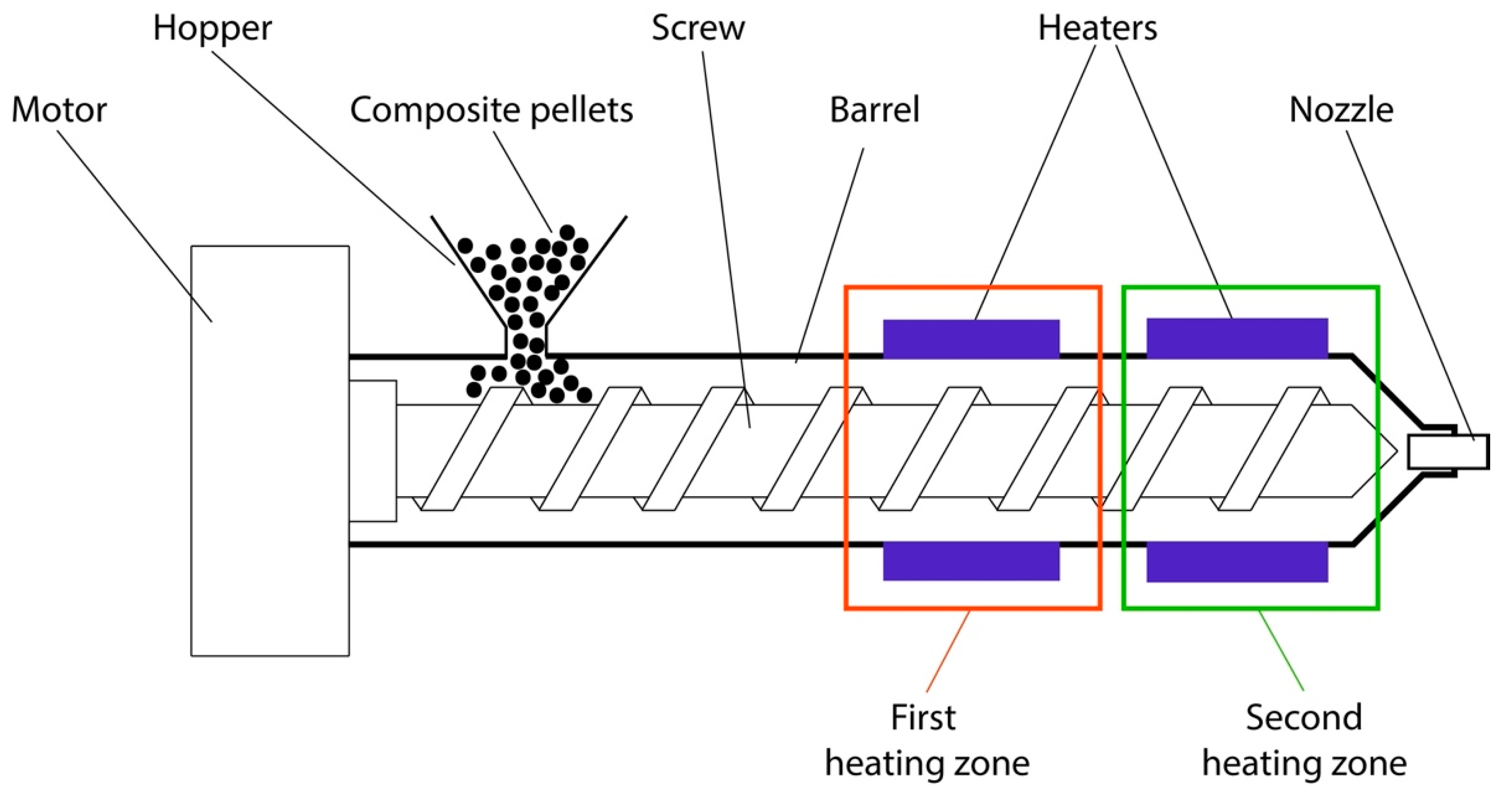
The single screw extruder was used to prepare the filaments with a constant diameter. The extrusion machine was equipped with two independent heating zones, as shown in Figure 2. The rotation speed of the screw is constant (38 rpm), and temperatures may be adjusted in the range of 25 °C to 300 °C in both heating zones. To control the extruded filament diameter, the extrusion machine enabled the exchange of the nozzle with different diameters.
In this paper, the ABS/CNT composites filaments with filler fractions of 0.99, 1.96, 4.76, and 9.09 wt.% were investigated. To obtain filaments with an appropriate diameter, the nozzle of a 1.7 mm diameter was used. The extrusion machine’s heated zones were set to 140 °C and 155 °C for the first and second zone, respectively. The lower extrusion temperature caused an insufficient flow of the melted matrix material, which resulted in clogging of the extruder nozzle and obtaining heterogeneous filament. On the other hand, higher extrusion temperatures caused the material to flow too rapidly, making it impossible to obtain a fixed diameter of the filament. Additionally, the increased temperature may cause thermal degradation of the polymer. During the filament extrusion process, it was observed that acetone was not completely evaporated despite drying the composite before the extrusion process. Excessive acetone evaporated in the high temperature of the extrusion process and caused the formation of an irregular-shaped filament with high internal porosity. The extrusion process had to be performed several times to obtain a high-quality material. ABS copolymer decomposes at 368 °C [35]; therefore, multiple thermal processing of ABS/CNT composite at max 240 °C does not have a significant impact on the mechanical properties of the material. Additionally, in the literature we found studies presenting the influence of multiple injection molding processes on the properties of ABS, which also confirm no significant effect on the mechanical properties of the polymer despite repeated thermal processing in the temperature range we used for the processing of ABS/CNT composites [36]. All of the resulting composite filaments had to be extruded four times to evaporate the remaining solvent completely. Finally, optimization of the extrusion process allowed us to obtain a continuous filament with a diameter ranging from 1.7 mm to 1.8 mm (Figure 3). The filaments were also characterized by high homogeneity and a lack of porosity.
2.3. FDM Printer and Printing Parameters
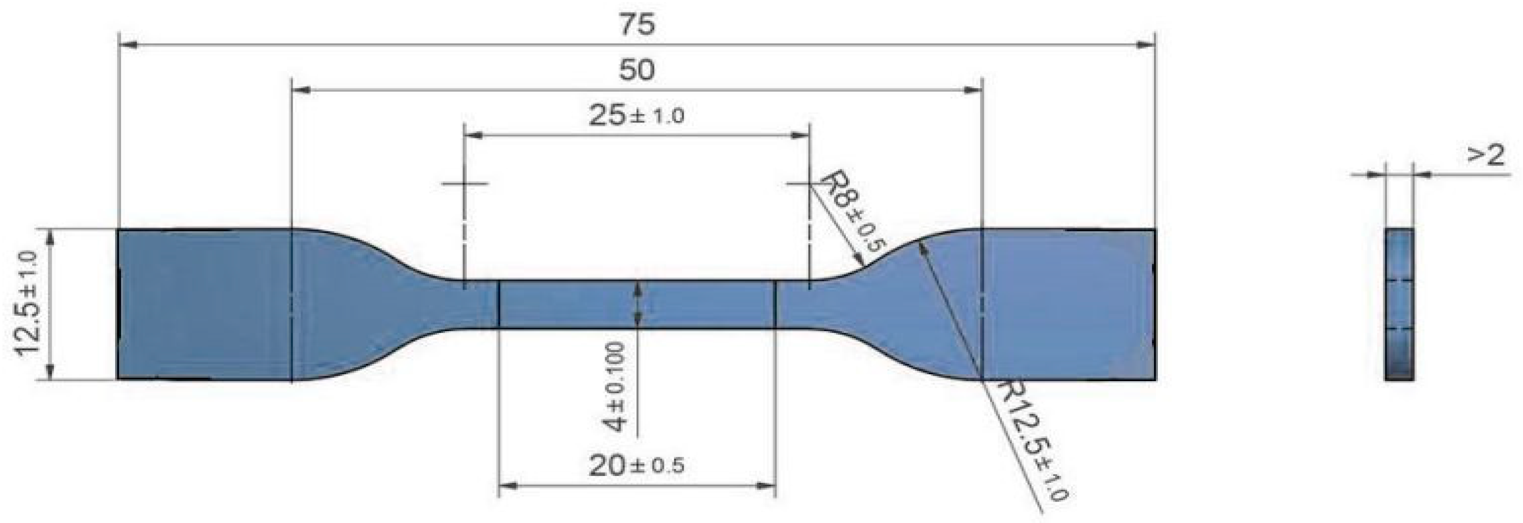
For the sample preparation, we used a commercial, low-end FDM printer, CTC Bizer 2X PRO, using Flashprint control software. The structure and mechanics of the Bizer FDM printer are typical for standard, unmodified direct drive printers. The diameter of the printed nozzle was 800 µm. Filaments with different amounts of filler were used to print samples for the mechanical and electrical tests. The shape and dimensions of test samples according to ISO standards are shown in Figure 4.
All test samples were printed at a nozzle temperature of 240 °C and a platform temperature of 110 °C. The layer height was set at 200 µm, printing speed at 30 mm/s, the fill pattern as line at 45°, and a 100% infill. The selected parameters allowed us to obtain high-quality samples without clogging the nozzle (Figure 5).
3. Results
3.1. Mechanical Properties
The mechanical properties of the printed samples from developed ABS/CNT composites filaments were measured by preparing a standard tensile properties test using the Cometech QC-506M2 machine. Since there are no standards for testing 3D printed elements, available standards for injection moulding of thermoplastics were used during the research. The methods and conditions for the tensile test were based directly on ISO 527-1:2012 and ISO 527-2:2012 standards. The speed of tensile testing was set to 1 mm/min.
Five specimens from each composite filament were printed and tested to reduce statistical uncertainty and determine the degree of microstructure and mechanical properties variability between samples. The mechanical properties of fabricated materials were also compared with pure polymer (ABS).
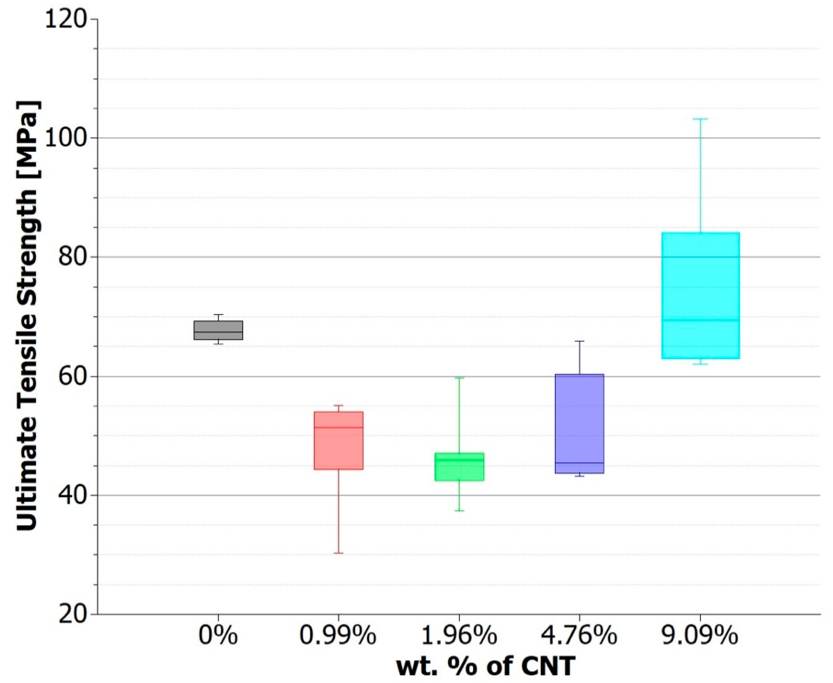
As shown in Figure 6, the tensile results of the ABS/CNT composites 3D prints demonstrate that tensile strength decreased for lower CNT content, below 5 wt.%. At the same time, specimens with 9.09 wt.% of filler showed higher tensile strength compared with pure ABS samples. Nano-filler was expected to increase the tensile strength of the composite, according to the standard theory of composite materials [37]. However, despite these expectations, the observed composite seemed to have, in some cases, a lower value of tensile strength than in the case of pure material. With low functional phase content, the strengthening effect can be overwhelmed by the printing defects resulting from non-optimal print parameters and the heterogeneity of the composite film.
Based on the obtained results, we observed an improvement in the mechanical properties of the composites with the increasing content of the CNT functional phase as it is described by the composite theory [38,39,40]. On the other hand, we observed the counterintuitive effect of lower values of the tensile strength of samples with low CNT content than for the pure ABS samples. It should be noted that the addition of nanoparticles may cause difficulties in the printing process, which was unknown for the pure polymer samples. Nanomaterials affected the rheological properties of the composite material, causing the non-uniform extrusion of material from the nozzle, and therefore induced voids inside the printed parts, caused the delamination of printed layers, and created problems with the adhesion of individual paths, etc. As a rule of thumb, we have estimated the mechanical percolation threshold for such composites at approximately 9% (a distinct increase of tensile strength value compared to samples with lower CNT content). In high CNT content composites, connected and tangled nanotubes occur, running along the whole length of the printed element and resulting in improved tensile strength of the composite. Below the threshold, too few nanotubes are tangled and connected together, reducing the cross-sectional area of the polymer and therefore acting as inclusions decreasing the tensile strength of the composite. The same effect of the reduced tensile strength of the composite below the percolation threshold compared to a pure polymer was described previously in the literature [41,42].
3.2. Electrical Properties
Direct currentresistivity measurements of 3D printed samples were carried out using a four-probe method. Rohde & Schwarz HM8112 multimeters were used during measurements. It should be noted that samples with electrical resistance above 200 MΩ were considered as non-conductive. To calculate samples’ resistivity, Equation (1) was used, where ρ is the volume resistivity, S is the cross-sections area, R is the resistance of the measured sample, and l is a length of the measured sample.
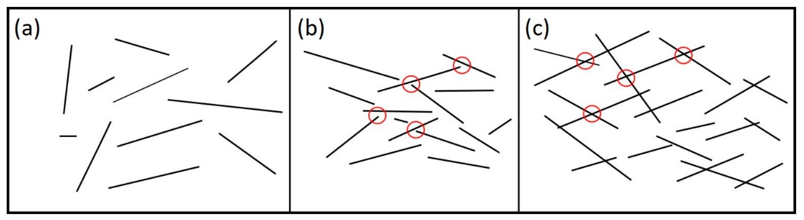
Our first attempts of resistance measurements was conducted at a constant voltage of 12 V. Tests showed that components printed from composites containing 0.99 and 1.96 wt.% of CNT exhibited high resistance (above 200 MΩ) and therefore were treated as non-conductive. When the CNT content increases to 4.76 wt.%, the electrical resistivity reduces to 2.5 Ωm. With the addition of 9.09 wt.% CNT, average resistivity reduces to 0.15 Ωm, which is a value that allows the material to be used in many practical applications. This phenomenon indicates that an increase of CNT content in ABS/CNT can promote the formation of multiple conductive paths on the surface and inside 3D printed elements due to the excellent electrical conductivity of CNT. This is at least twice the improvement in results than for the previously reported ABS/CNT filaments [43,44]. With the same rule of thumb as previously, we have estimated the electrical percolation threshold at the CNT content of 4.76 wt.%. It is worth mentioning that the electrical percolation threshold is much lower than the mechanical percolation. Composite with a CNT content of 4.76 wt.% shows electrical conductivity even though the mechanical percolation threshold is at much higher filler loading. The presence of a tunneling mechanism causes this phenomenon. Electrical connections between two conductive particles arise from two different mechanisms: mechanical contact between particles or electron tunneling effect. According to quantum tunneling theory, electrons can pass through insulator material, causing electrical current flow, under specific conditions. In other words, it is possible that a pair of conductive inclusions (CNT) dispersed in an insulating polymer matrix (ABS) is electrically connected, and electrons can pass from one inclusion to another, even if there is no physical connection between them [45,46]. It follows that even a smaller amount of the conductive functional phase of CNT can improve the conductive properties of a composite. However, only a larger amount of CNT can improve the mechanical properties, because to increase the tensile strength of a composite, it is necessary to form long carbon fibers from single nanotubes, and that is why it is necessary to connect them physically (Figure 7).
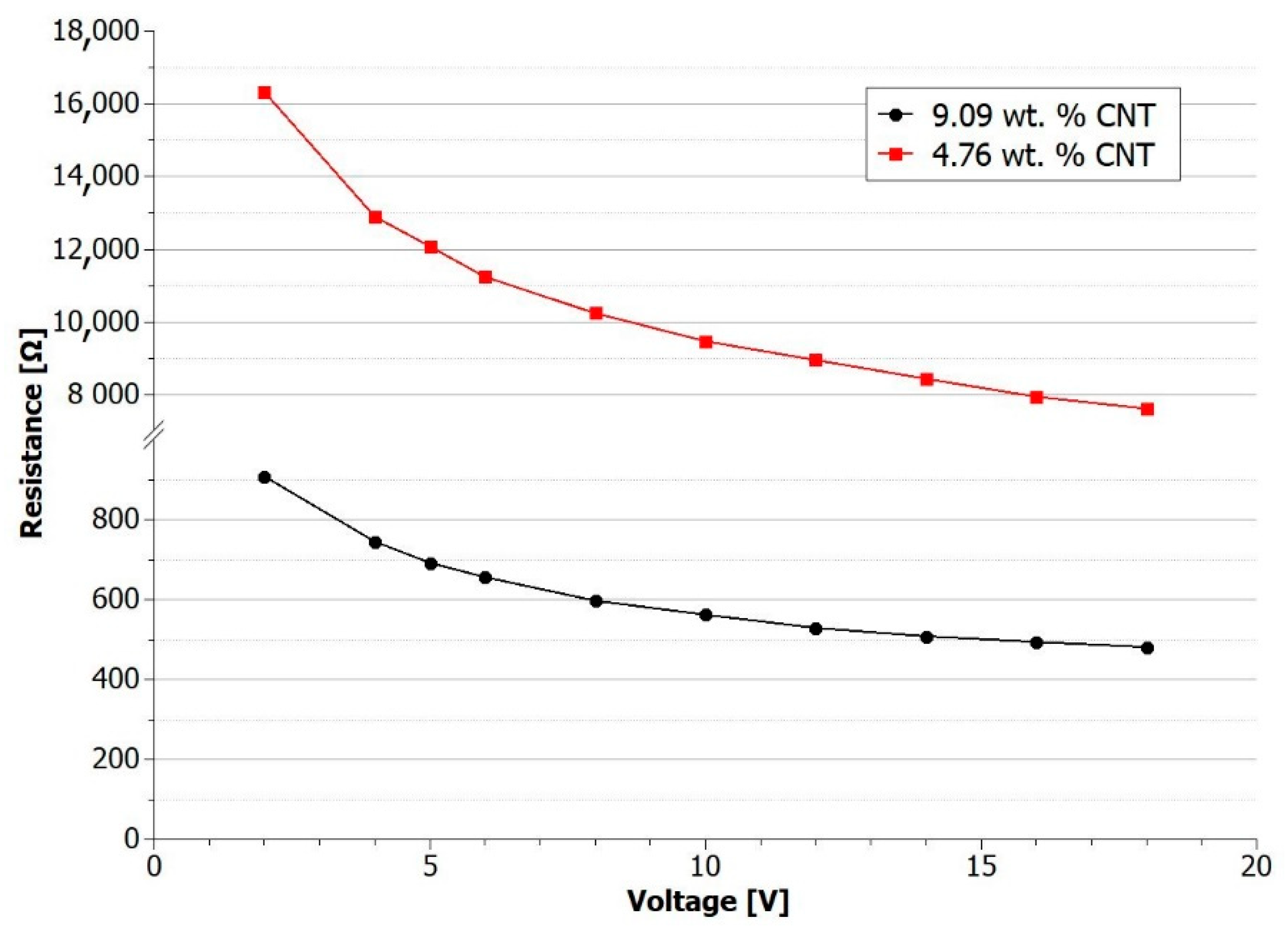
In order to confirm the occurrence of the tunneling effect in the developed composites, current-voltage characteristics of the printed elements were determined. In the case where the leading type of conductivity in the material is based on the tunnelling effect, the current-voltage characteristics are not linear. The non-linearity is due to the fact that CNTs are semiconductor materials, but also because the change in the electrical properties of the percolation network depends on external factors such as temperature or electric field manifesting as the decrease of junction resistance [47]. Figure 8 shows I–V characteristics for specimens printed with ABS/CNT filaments containing 4.76 and 9.09 wt.% of CNT.
The characteristics show a decrease in resistance as the voltage increases. This phenomenon is mainly caused by the increasing value of electrical current increasing the temperature of the composites, causing a decrease in the resistance of samples for higher voltages. Nanocomposites containing CNT are characterized by a negative temperature coefficient of resistivity (NTC effect), which means that the electrical resistivity of composite decreases during heating. The results obtained coincide with numerous literature reports related to nanocomposites [48,49,50].
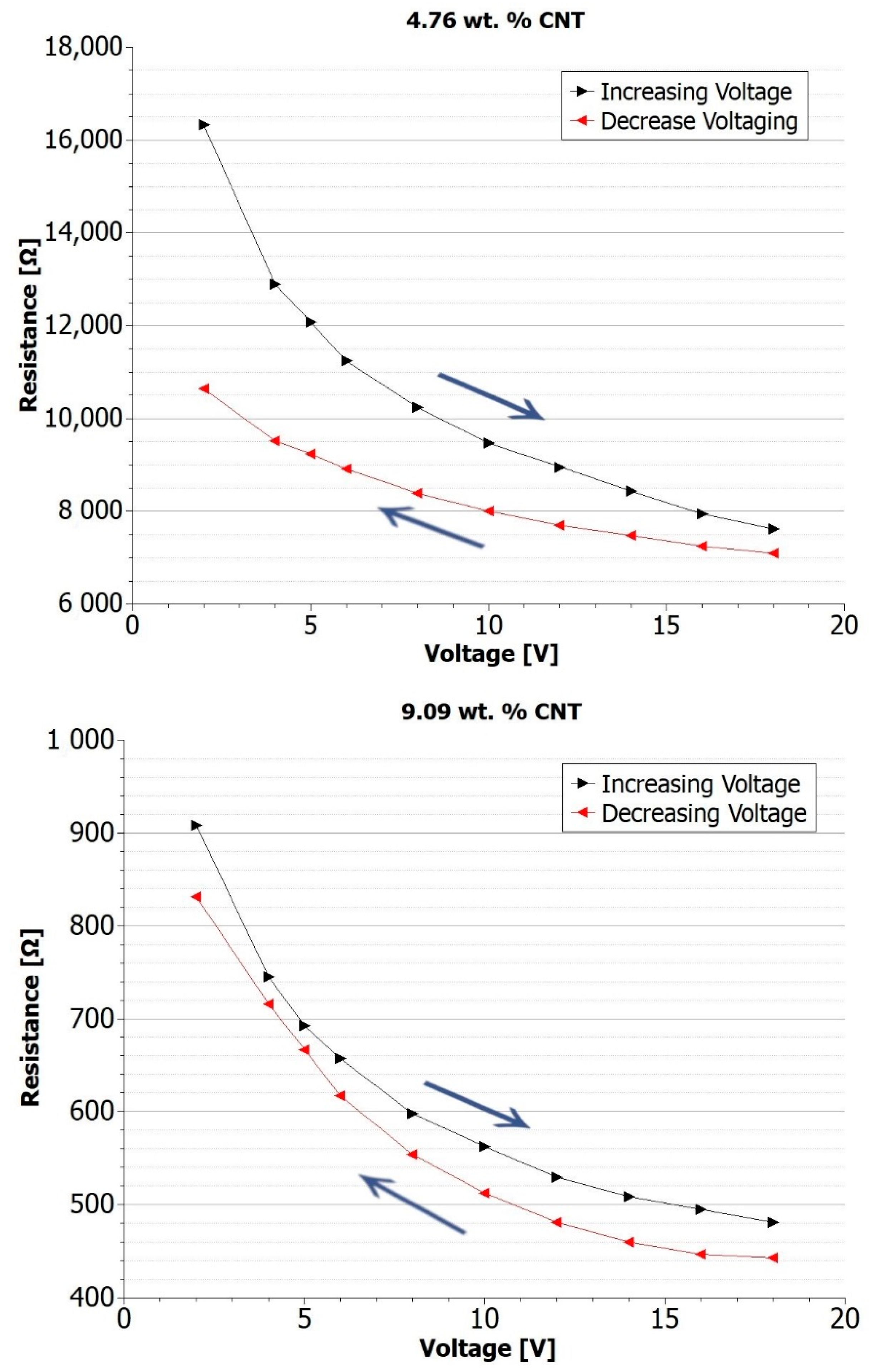
The current-voltage characteristics for increasing and decreasing voltage were also prepared. It is noted that increasing and decreasing voltage measured current curves do not follow the same path, and electrical hysteresis is visible. As shown in Figure 9, a small increase in measured current is observed during the decreasing voltage cycle. In the increasing voltage cycle, electrical conductivity is lower. This phenomenon is caused by the occurrence of hysteresis in the I–V characteristic of electron tunneling [51,52,53]. The electrical potential required to start the electron tunneling process is higher than the minimum potential needed to sustain the process. This results in improved conductivity of the composite when a higher voltage is applied first, and the tunneling mechanism is initiated in the higher number of connections between the CNTs. When a low voltage is applied initially, the tunneling process cannot start in such a large number of connections. It was also observed that the difference in conductivity is smaller for composites with higher CNT content. This is related to the higher number of CNT connections and explains that the tunneling distance is drastically reduced while the content of nanoparticles increases.
4. Conclusions
In this study, filaments based on ABS/CNT matrices were prepared for the FDM additive process. It was shown that with the FDM technique, we can fabricate complex shapes with the use of these composites. The results demonstrate that CNT content has a significant and nonlinear impact on mechanical and electrical properties. During the extrusion and printing of the developed filaments, it is important to apply optimal process parameters to obtain high-quality filaments and 3D printed elements. The key parameters are extrusion/print speed and head temperature. The speed must not be too high, as the appropriate amount of material is not applied. However, when it is very low, the print time is much longer, which is significant for industrial applications. On the other hand, if the temperature value is too low, the filament does not melt properly.
The tensile strength test showed that a small amount of CNT in the composite could decrease the maximum tensile strength of printed elements compared to those printed with pure ABS. Above the estimated mechanical percolation threshold, the addition of 9.09 wt.% of CNTs results in a 12.6% increase in tensile strength. This counterintuitive phenomenon of strength value decrease must be taken into consideration during the elaboration of new composite materials. On the other hand, the high content of CNTs favored for greater mechanical and electrical properties can be problematic for the processing of composite materials.
Electrical conductivity measurements showed that elements printed with composites containing 4.76 and 9.09 wt.% CNT are electrically conductive. For a fixed voltage value equal to 12 V, samples average resistivity reduces to 2.5 Ωm for 4.76 wt.% CNT and to 0.15 Ωm for 9.09 wt.% CNT. Current-voltage characteristics were determined for the developed materials. A significant influence of the tunneling mechanism on the electrical properties of ABS/CNT composites was observed. Non-linearity of the characteristics proves that the electrical conductivity is based in such composites on quantum tunneling. For materials with higher CNT content, the occurrence of physical contacts between individual nanotubes forming conductive pathways inside the composite becomes more and more critical, resulting in a decrease in resistance at higher values of measurement voltages than for composites with lower CNT content. For material containing 4.76 wt.% CNTs, the decrease in resistance value during a voltage change from 2 to 18V was 83% and for material containing 9.09 wt.% CNTs it was 88%. The research also showed the occurrence of resistivity hysteresis, depending on the applied voltage. It was observed that the resistivity of the composite is lower when the voltage value decreases compared to the resistivity for an increasing voltage. This relation is directly related to the hysteresis of the I-V relation occurring during the tunneling mechanism.
Additional work needs to be done to explore the influence of the other carbon and metal fillers on mechanical and electrical properties of composites, printing parameters (speed, temperature, infill, layer height etc.), and the porosity of the printed components. Yet, at this moment the obtained and presented results demonstrate that ABS/CNT composite filaments are promising materials for FDM additive manufacturing and may open the possibilities for many new applications in advanced industrial fields such as structural electronics, intelligent structures, and embedded sensors.
Author Contributions
Conceptualization, B.P. and A.S.; methodology, B.P., P.M., A.S., and M.S.; validation, P.M. and A.S.; formal analysis, B.P., A.S., and M.S.; investigation, P.M. and A.S.; resources, A.S. and M.S.; writing—original draft preparation, B.P.; writing—review and editing, M.S.; visualization, B.P.; supervision, A.S. and M.S.; project administration, M.S.; funding acquisition, M.S. All authors have read and agreed to the published version of the manuscript.
Funding
This work was financially supported by the Foundation for Polish Science within the FirstTEAM/2016-1/7 project.
Institutional Review Board Statement
Not applicable.
Informed Consent Statement
Not applicable.
Data Availability Statement
The data presented in this study are available on request from the corresponding author.
Acknowledgments
This work was supported by Institute of Metrology and Biomedical Engineering, Warsaw University of Technology, Faculty of Mechatronics.
Conflicts of Interest
The authors declare no conflict of interest.
References
- Kruth, J.-P.; Leu, M.C.; Nakagawa, T. Progress in Additive Manufacturing and Rapid Prototyping. CIRP Ann. Manuf. Technol. 1998, 47, 525–540. [Google Scholar] [CrossRef]
- Winder, J.; Bibb, R. Medical Rapid Prototyping Technologies: State of the Art and Current Limitations for Application in Oral and Maxillofacial Surgery. J. Oral Maxillofac. Surg. 2005, 63, 1006–1015. [Google Scholar] [CrossRef] [PubMed] [Green Version]
- Berman, B. 3-D Printing: The New Industrial Revolution. Bus. Horiz. 2012, 55, 155–162. [Google Scholar] [CrossRef]
- Moon, S.K.; Tan, Y.E.; Hwang, J.; Yoon, Y.-J. Application of 3D Printing Technology for Designing Light-Weight Unmanned Aerial Vehicle Wing Structures. Int. J. Precis. Eng. Manuf. Green Technol. 2014, 1, 223–228. [Google Scholar] [CrossRef]
- Ackland, D.C.; Robinson, D.; Redhead, M.; Lee, P.V.S.; Moskaljuk, A.; Dimitroulis, G. A Personalized 3D-Printed Prosthetic Joint Replacement for the Human Temporomandibular Joint: From Implant Design to Implantation. J. Mech. Behav. Biomed. Mater. 2017, 69, 404–411. [Google Scholar] [CrossRef] [PubMed]
- Delgado Camacho, D.; Clayton, P.; O’Brien, W.J.; Seepersad, C.; Juenger, M.; Ferron, R.; Salamone, S. Applications of Additive Manufacturing in the Construction Industry—A Forward-Looking Review. Autom. Constr. 2018, 89, 110–119. [Google Scholar] [CrossRef]
- Yap, Y.L.; Yeong, W.Y. Additive Manufacture of Fashion and Jewellery Products: A Mini Review. Virtual Phys. Prototyp. 2014, 9, 195–201. [Google Scholar] [CrossRef]
- Podsiadły, B.; Skalski, A.; Wałpuski, B.; Słoma, M. Heterophase Materials for Fused Filament Fabrication of Structural Electronics. J. Mater. Sci. Mater. Electron. 2019, 30, 1236–1245. [Google Scholar] [CrossRef]
- Youssef, A.; Hollister, S.J.; Dalton, P.D. Additive Manufacturing of Polymer Melts for Implantable Medical Devices and Scaffolds. Biofabrication 2017, 9, 012002. [Google Scholar] [CrossRef]
- Ngo, T.D.; Kashani, A.; Imbalzano, G.; Nguyen, K.T.Q.; Hui, D. Additive Manufacturing (3D Printing): A Review of Materials, Methods, Applications and Challenges. Compos. Part B Eng. 2018, 143, 172–196. [Google Scholar] [CrossRef]
- Attaran, M. The Rise of 3-D Printing: The Advantages of Additive Manufacturing over Traditional Manufacturing. Bus. Horiz. 2017, 60, 677–688. [Google Scholar] [CrossRef]
- Khosravani, M.R.; Reinicke, T. On the Environmental Impacts of 3D Printing Technology. Appl. Mater. Today 2020, 20, 100689. [Google Scholar] [CrossRef]
- Guo, N.; Leu, M.C. Additive Manufacturing: Technology, Applications and Research Needs. Front. Mech. Eng. 2013, 8, 215–243. [Google Scholar] [CrossRef]
- Bourell, D.; Kruth, J.P.; Leu, M.; Levy, G.; Rosen, D.; Beese, A.M.; Clare, A. Materials for Additive Manufacturing. CIRP Ann. 2017, 66, 659–681. [Google Scholar] [CrossRef]
- Abeykoon, C.; Sri-Amphorn, P.; Fernando, A. Optimization of Fused Deposition Modeling Parameters for Improved PLA and ABS 3D Printed Structures. Int. J. Lightweight Mater. Manuf. 2020, 3, 284–297. [Google Scholar] [CrossRef]
- Wang, P.; Zou, B.; Xiao, H.; Ding, S.; Huang, C. Effects of Printing Parameters of Fused Deposition Modeling on Mechanical Properties, Surface Quality, and Microstructure of PEEK. J. Mater. Process. Technol. 2019, 271, 62–74. [Google Scholar] [CrossRef]
- Gebisa, A.W.; Lemu, H.G. Investigating Effects of Fused-Deposition Modeling (FDM) Processing Parameters on Flexural Properties of ULTEM 9085 Using Designed Experiment. Materials 2018, 11, 500. [Google Scholar] [CrossRef] [Green Version]
- Akhoundi, B.; Behravesh, A.H.; Bagheri Saed, A. An Innovative Design Approach in Three-Dimensional Printing of Continuous Fiber–Reinforced Thermoplastic Composites via Fused Deposition Modeling Process: In-Melt Simultaneous Impregnation. Proc. Inst. Mech. Eng. Part B J. Eng. Manuf. 2020, 234, 243–259. [Google Scholar] [CrossRef]
- Bettini, P.; Alitta, G.; Sala, G.; Di Landro, L. Fused Deposition Technique for Continuous Fiber Reinforced Thermoplastic. J. Mater. Eng. Perform. 2017, 26, 843–848. [Google Scholar] [CrossRef]
- Dong, G.; Tang, Y.; Li, D.; Zhao, Y.F. Mechanical Properties of Continuous Kevlar Fiber Reinforced Composites Fabricated by Fused Deposition Modeling Process. Procedia Manuf. 2018, 26, 774–781. [Google Scholar] [CrossRef]
- Liao, G.; Li, Z.; Cheng, Y.; Xu, D.; Zhu, D.; Jiang, S.; Guo, J.; Chen, X.; Xu, G.; Zhu, Y. Properties of Oriented Carbon Fiber/Polyamide 12 Composite Parts Fabricated by Fused Deposition Modeling. Mater. Des. 2018, 139, 283–292. [Google Scholar] [CrossRef]
- Shang, J.; Tian, X.; Luo, M.; Zhu, W.; Li, D.; Qin, Y.; Shan, Z. Controllable Inter-Line Bonding Performance and Fracture Patterns of Continuous Fiber Reinforced Composites by Sinusoidal-Path 3D Printing. Compos. Sci. Technol. 2020, 192, 108096. [Google Scholar] [CrossRef]
- Sodeifian, G.; Ghaseminejad, S.; Yousefi, A.A. Preparation of Polypropylene/Short Glass Fiber Composite as Fused Deposition Modeling (FDM) Filament. Results Phys. 2019, 12, 205–222. [Google Scholar] [CrossRef]
- Zhang, W.; Cotton, C.; Sun, J.; Heider, D.; Gu, B.; Sun, B.; Chou, T.-W. Interfacial Bonding Strength of Short Carbon Fiber/Acrylonitrile-Butadiene-Styrene Composites Fabricated by Fused Deposition Modeling. Compos. Part B Eng. 2018, 137, 51–59. [Google Scholar] [CrossRef]
- Weng, Z.; Wang, J.; Senthil, T.; Wu, L. Mechanical and Thermal Properties of ABS/Montmorillonite Nanocomposites for Fused Deposition Modeling 3D Printing. Mater. Des. 2016, 102, 276–283. [Google Scholar] [CrossRef]
- Yang, L.; Chen, Y.; Wang, M.; Shi, S.; Jing, J. Fused Deposition Modeling 3D Printing of Novel Poly(Vinyl Alcohol)/Graphene Nanocomposite with Enhanced Mechanical and Electromagnetic Interference Shielding Properties. Ind. Eng. Chem. Res. 2020, 59, 8066–8077. [Google Scholar] [CrossRef]
- Francis, V.; Jain, P.K. Achieving Improved Dielectric, Mechanical, and Thermal Properties of Additive Manufactured Parts via Filament Modification Using OMMT-Based Nanocomposite. Prog. Addit. Manuf. 2017, 2, 109–115. [Google Scholar] [CrossRef]
- Khosravani, M.R. Composite Materials Manufacturing Processes. Appl. Mech. Mater. 2011, 110–116, 1361–1367. [Google Scholar] [CrossRef]
- Podsiadły, B.; Skalski, A.; Słoma, M. Conductive ABS/Ni Composite Filaments for Fused Deposition Modeling of Structural Electronics. In Mechatronics 2019: Recent Advances towards Industry 4.0; Szewczyk, R., Krejsa, J., Nowicki, M., Ostaszewska-Liżewska, A., Eds.; Advances in Intelligent Systems and Computing; Springer International Publishing: Cham, Switzerland, 2020; Volume 1044, pp. 62–70. ISBN 978-3-030-29992-7. [Google Scholar]
- Gonçalves, J.; Lima, P.; Krause, B.; Pötschke, P.; Lafont, U.; Gomes, J.R.; Abreu, C.S.; Paiva, M.C.; Covas, J.A. Electrically Conductive Polyetheretherketone Nanocomposite Filaments: From Production to Fused Deposition Modeling. Polymers 2018, 10, 925. [Google Scholar] [CrossRef] [Green Version]
- Lamberti, P.; Spinelli, G.; Kuzhir, P.P.; Guadagno, L.; Naddeo, C.; Romano, V.; Kotsilkova, R.; Angelova, P.; Georgiev, V. Evaluation of Thermal and Electrical Conductivity of Carbon-Based PLA Nanocomposites for 3D Printing; AIP Publishing LLC: Ischia, Italy, 2018; p. 020158. [Google Scholar]
- Zhang, X.; Chen, L.; Mulholland, T.; Osswald, T.A. Characterization of Mechanical Properties and Fracture Mode of PLA and Copper/PLA Composite Part Manufactured by Fused Deposition Modeling. SN Appl. Sci. 2019, 1, 616. [Google Scholar] [CrossRef] [Green Version]
- Ryder, M.A.; Lados, D.A.; Iannacchione, G.S.; Peterson, A.M. Fabrication and Properties of Novel Polymer-Metal Composites Using Fused Deposition Modeling. Compos. Sci. Technol. 2018, 158, 43–50. [Google Scholar] [CrossRef]
- Fafenrot, S.; Grimmelsmann, N.; Wortmann, M.; Ehrmann, A. Three-Dimensional (3D) Printing of Polymer-Metal Hybrid Materials by Fused Deposition Modeling. Materials 2017, 10, 1199. [Google Scholar] [CrossRef] [PubMed] [Green Version]
- Ma, H.; Tong, L.; Xu, Z.; Fang, Z.; Jin, Y.; Lu, F. A Novel Intumescent Flame Retardant: Synthesis and Application in ABS Copolymer. Polym. Degrad. Stab. 2007, 92, 720–726. [Google Scholar] [CrossRef]
- Żenkiewicz, M.; Rytlewski, P.; Moraczewski, K.; Stepczyńska, M.; Karasiewicz, T.; Malinowski, R.; Ostrowicki, W. Some Effects of Multiple Injection Moulding on Selected Properties of ABS. J. Achiev. Mater. Manuf. Eng. 2009, 37, 361–368. [Google Scholar]
- Balazs, A.C.; Emrick, T.; Russell, T.P. Nanoparticle Polymer Composites: Where Two Small Worlds Meet. Science 2006, 314, 1107–1110. [Google Scholar] [CrossRef]
- Arash, B.; Wang, Q.; Varadan, V.K. Mechanical Properties of Carbon Nanotube/Polymer Composites. Sci. Rep. 2014, 4, 6479. [Google Scholar] [CrossRef]
- Thostenson, E.T.; Ren, Z.; Chou, T.-W. Advances in the Science and Technology of Carbon Nanotubes and Their Composites: A Review. Compos. Sci. Technol. 2001, 61, 1899–1912. [Google Scholar] [CrossRef] [Green Version]
- Zhang, W.; Deng, X.; Sui, G.; Yang, X. Improving Interfacial and Mechanical Properties of Carbon Nanotube-Sized Carbon Fiber/Epoxy Composites. Carbon 2019, 145, 629–639. [Google Scholar] [CrossRef]
- Meng, S.; He, H.; Jia, Y.; Yu, P.; Huang, B.; Chen, J. Effect of Nanoparticles on the Mechanical Properties of Acrylonitrile-Butadiene-Styrene Specimens Fabricated by Fused Deposition Modeling. J. Appl. Polym. Sci. 2017, 134. [Google Scholar] [CrossRef]
- Nadernezhad, A.; Unal, S.; Khani, N.; Koc, B. Material Extrusion-Based Additive Manufacturing of Structurally Controlled Poly(Lactic Acid)/Carbon Nanotube Nanocomposites. Int. J. Adv. Manuf. Technol. 2019, 102, 2119–2132. [Google Scholar] [CrossRef]
- Sezer, H.K.; Eren, O. FDM 3D Printing of MWCNT Re-Inforced ABS Nano-Composite Parts with Enhanced Mechanical and Electrical Properties. J. Manuf. Process. 2019, 37, 339–347. [Google Scholar] [CrossRef]
- Dul, S.; Pegoretti, A.; Fambri, L. Effects of the Nanofillers on Physical Properties of Acrylonitrile-Butadiene-Styrene Nanocomposites: Comparison of Graphene Nanoplatelets and Multiwall Carbon Nanotubes. Nanomaterials 2018, 8, 674. [Google Scholar] [CrossRef] [PubMed] [Green Version]
- Hu, N.; Karube, Y.; Yan, C.; Masuda, Z.; Fukunaga, H. Tunneling Effect in a Polymer/Carbon Nanotube Nanocomposite Strain Sensor. Acta Mater. 2008, 56, 2929–2936. [Google Scholar] [CrossRef] [Green Version]
- Razavi, R.; Zare, Y.; Rhee, K.Y. The Roles of Interphase and Filler Dimensions in the Properties of Tunneling Spaces between CNT in Polymer Nanocomposites. Polym. Compos. 2019, 40, 801–810. [Google Scholar] [CrossRef]
- Dawson, J.C.; Adkins, C.J. Conduction Mechanisms in Carbon-Loaded Composites. J. Phys. Condens. Matter 1996, 8, 8321–8338. [Google Scholar] [CrossRef]
- Xiang, Z.-D.; Chen, T.; Li, Z.-M.; Bian, X.-C. Negative Temperature Coefficient of Resistivity in Lightweight Conductive Carbon Nanotube/Polymer Composites. Macromol. Mater. Eng. 2009, 294, 91–95. [Google Scholar] [CrossRef]
- Mohd Radzuan, N.A.; Sulong, A.B.; Hui, D.; Verma, A. Electrical Conductivity Performance of Predicted Modified Fibre Contact Model for Multi-Filler Polymer Composite. Polymers 2019, 11, 1425. [Google Scholar] [CrossRef] [Green Version]
- Tang, H.; Chen, X.; Luo, Y. Studies on the PTC/NTC Effect of Carbon Black Filled Low Density Polyethylene Composites. Eur. Polym. J. 1997, 33, 1383–1386. [Google Scholar] [CrossRef]
- Kroó, N.; Varró, S.; Rácz, P. Hysteresis Phenomena in Electron Tunnelling, Induced by Surface Plasmons. J. Mod. Opt. 2013, 60, 79–85. [Google Scholar] [CrossRef] [Green Version]
- Robert-Peillard, A.; Rotkin, S.V. Modeling Hysteresis Phenomena in Nanotube Field-Effect Transistors. IEEE Trans. Nanotechnol. 2005, 4, 284–288. [Google Scholar] [CrossRef]
- Wu, S.W.; Ogawa, N.; Nazin, G.V.; Ho, W. Conductance Hysteresis and Switching in a Single-Molecule Junction. J. Phys. Chem. C 2008, 112, 5241–5244. [Google Scholar] [CrossRef]
Figure 1.
SEM (scanning electron microscope) micrograph of carbon nanotube functional filler.

Figure 2.
Schematic diagram of a single screw extruder used for the composite filaments fabrication.
Figure 2.
Schematic diagram of a single screw extruder used for the composite filaments fabrication.

Figure 3.
Extruded composite filaments filled with 9.09 wt.% of carbon nanotubes, with diameters in the range of 1.7–1.8 mm.
Figure 3.
Extruded composite filaments filled with 9.09 wt.% of carbon nanotubes, with diameters in the range of 1.7–1.8 mm.

Figure 4.
Schematic drawing with dimensions of 3D printed samples for mechanical tests according to ISO 527-2 standard.
Figure 4.
Schematic drawing with dimensions of 3D printed samples for mechanical tests according to ISO 527-2 standard.

Figure 5.
3D printed samples for mechanical and electrical measurements printed from acrylonitrile butadiene styrene/carbon nanotube (ABS/CNT) composites. Quality of the samples is acceptable for further tests.
Figure 5.
3D printed samples for mechanical and electrical measurements printed from acrylonitrile butadiene styrene/carbon nanotube (ABS/CNT) composites. Quality of the samples is acceptable for further tests.

Figure 6.
Comparison of ultimate tensile strength values for composite samples with different CNTs loading (from 0.99 to 9.09 wt.%), and with ABS reference samples (0 wt.% of CNTs).
Figure 6.
Comparison of ultimate tensile strength values for composite samples with different CNTs loading (from 0.99 to 9.09 wt.%), and with ABS reference samples (0 wt.% of CNTs).

Figure 7.
Schematic of percolation mechanisms. (a) CNT amount below the percolation threshold (b) CNT amount above the electrical but below the mechanical percolation threshold. Circles show examples of places where electron tunneling may occur due to a thin layer of insulating polymer between nanotubes. (c) CNT amount above the mechanical percolation threshold. Circles show examples of places where physical contacts of nanotubes are visible. Nanotube bonds result in a long carbon fiber, which improves the mechanical properties of the composite.

Figure 8.
Electrical resistance values of conductive composite samples under different values of voltage applied for I–V measurements.
Figure 8.
Electrical resistance values of conductive composite samples under different values of voltage applied for I–V measurements.

Figure 9.
Electrical resistance values of conductive composite samples under different values of voltage applied and different schemes of I–V measurement (increasing and decreasing voltage load applied).
Figure 9.
Electrical resistance values of conductive composite samples under different values of voltage applied and different schemes of I–V measurement (increasing and decreasing voltage load applied).

Publisher’s Note: MDPI stays neutral with regard to jurisdictional claims in published maps and institutional affiliations. |
© 2021 by the authors. Licensee MDPI, Basel, Switzerland. This article is an open access article distributed under the terms and conditions of the Creative Commons Attribution (CC BY) license (http://creativecommons.org/licenses/by/4.0/).
Share and Cite
MDPI and ACS Style
Podsiadły, B.; Matuszewski, P.; Skalski, A.; Słoma, M. Carbon Nanotube-Based Composite Filaments for 3D Printing of Structural and Conductive Elements. Appl. Sci. 2021, 11, 1272. https://0-doi-org.brum.beds.ac.uk/10.3390/app11031272
AMA Style
Podsiadły B, Matuszewski P, Skalski A, Słoma M. Carbon Nanotube-Based Composite Filaments for 3D Printing of Structural and Conductive Elements. Applied Sciences. 2021; 11(3):1272. https://0-doi-org.brum.beds.ac.uk/10.3390/app11031272
Chicago/Turabian StylePodsiadły, Bartłomiej, Piotr Matuszewski, Andrzej Skalski, and Marcin Słoma. 2021. "Carbon Nanotube-Based Composite Filaments for 3D Printing of Structural and Conductive Elements" Applied Sciences 11, no. 3: 1272. https://0-doi-org.brum.beds.ac.uk/10.3390/app11031272
Note that from the first issue of 2016, this journal uses article numbers instead of page numbers. See further details here.