Review of Dew Point Evaporative Cooling Technology for Air Conditioning Applications


1
Department of Cryogenics and Aerospace Engineering, Faculty of Mechanical and Power Engineering, Wroclaw University of Science and Technology, 27 Wyspiański st., 50-370 Wroclaw, Poland
2
Argonne National Laboratory, 9700 S Cass Ave, Lemont, IL 60439, USA
*
Author to whom correspondence should be addressed.
Appl. Sci. 2021, 11(3), 934; https://0-doi-org.brum.beds.ac.uk/10.3390/app11030934
Submission received: 30 November 2020
/
Revised: 16 January 2021
/
Accepted: 16 January 2021
/
Published: 20 January 2021
(This article belongs to the Special Issue Fundamentals and Recent Advances in Heating, Ventilation, and Air-Conditioning Systems (HVAC))
Abstract
:Indirect evaporative cooling has the potential to significantly improve the natural environment. It follows from a significant reduction in electricity consumption in the hot period, and hence lower operating costs for cooling systems. This paper presents the current state of knowledge and research directions on dew point indirect evaporative cooling. It was found that researchers focus on the development of dew point indirect evaporative coolers (DPIEC) by improving its design, geometry, water distribution, and new porous materials implementation. To evaluate the performance of new types of DPIEC, different methods are used by the scientists. Finally, optimized devices are studied in terms of their performance in different systems, like hybrid and desiccant systems, considering different climate conditions. Potential directions of development of evaporative technologies were indicated, such as increasing the coefficient of performance of solid desiccant evaporative cooling systems, developing novel geometry, and efficient water distribution, including development of porous materials.
1. Introduction
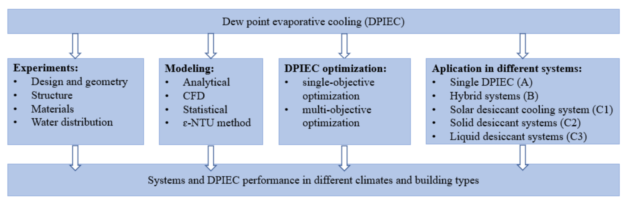
Primary energy consumption is increasing year by year, mainly due to economic development and the growth of the human population in the world [1]. The construction sector accounts for 36% of global energy consumption [2]. The International Energy Agency reports that the energy intensity for space cooling increased by 2.7%, while an improvement for space heating (−2%) and lighting (−1.4%) was observed. The energy intensity for water heating, cooking, and appliances remained steady. Space cooling is the fastest-growing consumer of electricity in buildings; its energy intensity has been constantly rising since 2014 [2]. It is caused by economic and population growth and intensive urbanization. The cooling energy needed in the summer period is in most cases generated by electrically-powered compressor systems. Therefore, alternative methods of producing cooling energy, which will allow operating costs of air-conditioning systems to be minimized while ensuring thermal comfort, are being constantly searched for. A proven solution is evaporative cooling, which can provide cheap cooling energy because of its effective evaporation process in wet channels of the dew point indirect evaporative coolers (DPIEC) used to cool the air. The dew point evaporative coolers have been extensively studied by many researchers in recent years. This paper discusses selected studies in the field of dew point evaporative cooling. A literature review was performed to present current directions of development of this technology to highlight the challenges that await scientists aiming to develop an alternative cooling system based on dew point evaporative cooling. In recent years, many publications have appeared that have set new directions for research in this field. The literature review was carried out according to the thematic division presented in Figure 1. The division covers the most important areas of the field of evaporative dew point cooling. The researchers focus on indirect evaporative cooling (IEC) development by improving its design, geometry, water distribution, and new porous materials implementation. To evaluate performance of the new types of DPIEC, different methods and software were used. Finally, the optimized devices were studied in terms of their performance in different systems, such as hybrid and desiccant systems. It follows from the fact that DPIEC does not decrease the humidity ratio for entire operational conditions (ambient airflow), hence in humid and moderate conditions the air needs to be dehumidified in an additional device (desiccant system or cooling coil). For some indirect evaporative coolers, the condensation of water vapor in a product channel may occur. This phenomenon is also considered in this study.
2. Methods
The search methodology was based on key strings used in the five searches presented in Table 1. For each search, the duplicates were excluded by comparing lists of articles. It should be underlined that the final list was compiled with some “related articles” prompted by the Scopus algorithm. Authors matched selected articles to the presented research areas in Figure 1. In total 386 documents were analyzed.
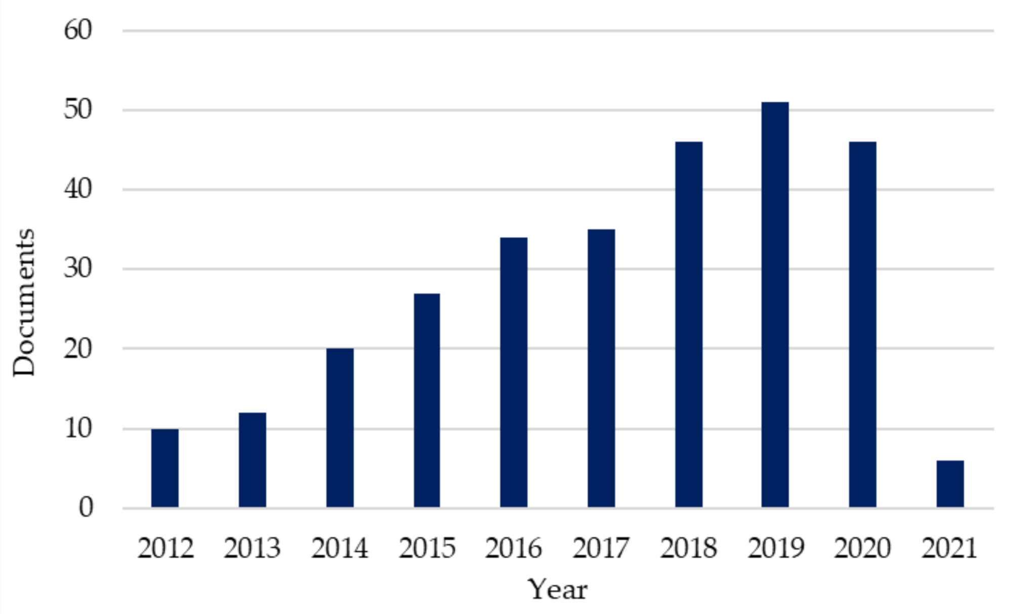
Figure 2 presents the total number of documents from 2012 to 2021. Since 2012, until 2019, the number of published articles in the field of evaporative cooling has been steadily increasing. The total number of articles from 2012 is 287, including all keywords listed Table 1. In the period from 2017 to 2021, there were 187 articles in total which were considered to be included in this study.
3. General Presentation of Technology
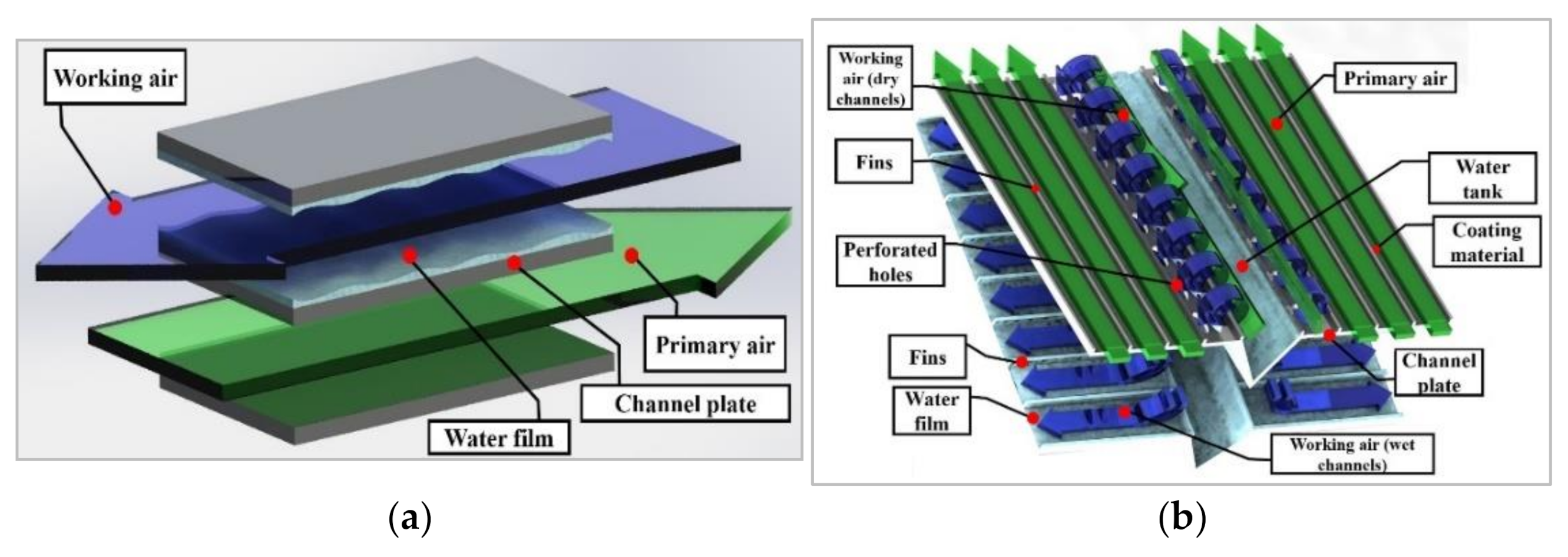
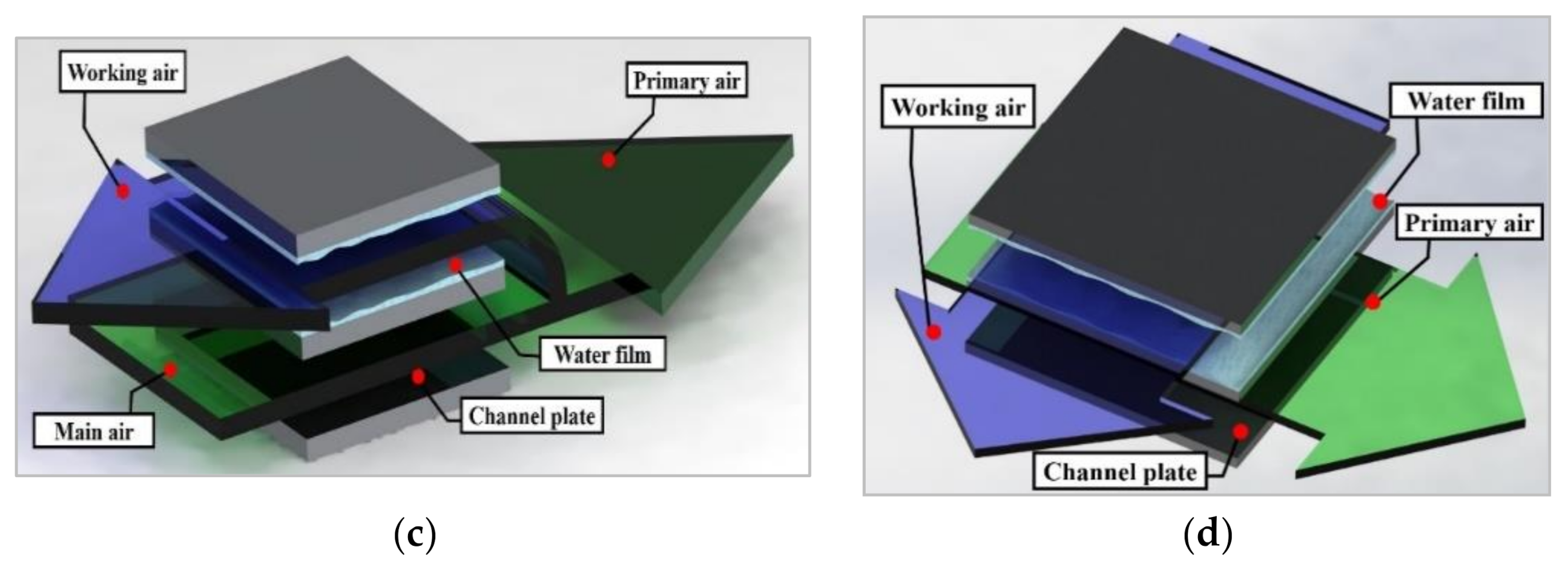
The indirect evaporative cooling system provides only sensible cooling to the processed air without any moisture addition. In an indirect evaporative cooler, the product air passes the dry channels, and the working air passes through the wet channels on the opposite side of the heat exchanger plate. The working air absorbs heat from the product air, and therefore the product air is cooled without adding any moisture to the air. At the same time, latent heat (related to water evaporation) is transferred to the working air. Main types of typical indirect evaporative coolers and dew point indirect evaporative coolers are shown in the Figure 3. Due to not adding moisture to the supply air, the IEC system is more attractive than direct evaporative devices for domestic applications. IEC units are made in the form of typical heat recovery recuperators: counter-flow (Figure 3a) and cross-flow (Figure 3d). One of the first concepts of achieving higher efficiency with indirect evaporative air cooling was presented in 1935, when Ray [3] published his patent of the air conditioning system where the ambient air was cooled below its inlet wet bulb temperature without mechanical refrigeration. This was achieved by the combination of direct and indirect evaporative cooling. In 1976, in the former USSR, Prof. Valeriy Maisotsenko developed his first ideas of the Maisotsenko-Cycle (M-Cycle) utilized in the regenerative and counter-flow exchangers. He patented his first devices (patents SU No 571,669 and 979,796 [4]). In recent years, several reviews of indirect evaporative cooling have been conducted. In 2019, Yang et al. presented evaporative cooling combined with selected technologies (desiccants, membranes) [5]. In 2018, Dizaji et al. focused on application of the DPIEC in air-conditioning. They summarized and discussed different methods of M-Cycle device evaluation. In 2016, two reviews were published by Mahmood et al. [6] and Cuce and Riffat [7]. Mahmood mainly presented applications such as the M-Cycle cooling tower and conception of gas turbines. Cuce and Riffat focused on dew point evaporative cooling in building applications.
The key performance indicators that describe a dew point indirect evaporative cooler are wet bulb and dry bulb effectiveness, calculated from the following equations:
—inlet product air temperature, °C
—outlet product air temperature, °C
—wet bulb inlet working air temperature, °C
—dew point inlet product air temperature, °C
Third performance indicator is electrical coefficient of performance (COP or EER—energy efficiency ratio):
—system cooling capacity, kW
—power consumed, kW
4. Dew Point Evaporative Coolers Research
4.1. Experimental Studies of DPIEC Performance
Indirect evaporative coolers consume electricity and water for the production of cooling energy. Their effectiveness depends on the device geometry and quality of water distribution in wet channels. It should be emphasized that dew point devices achieve EER values of 40, which is an advantage compared to typical compressor systems. Nevertheless, scientists are striving to reduce electricity consumption by modifying the geometry of evaporative exchangers. Regarding the method of supplying water to evaporative exchangers, water distribution systems in the exchangers are developed and improved through the use of special hydrophobic coatings or porous materials, allowing for capillary distribution of water in the cooler. There are some studies focusing on the pressure drop reduction in indirect evaporative coolers. Antonellis [9] analyzed the performance of different IEC geometry and flow arrangement (counter and parallel water). They examined how different plates’ protrusion and pitch affects IEC wet bulb effectiveness and pressure drop. It was found that plates geometry influences both surface wettability and heat transfer rate. The parallel water distribution and flow arrangement causes higher wet bulb effectiveness and lower pressure drop, compared to the counter flow configuration. Some authors focused on the coolers’ improvements by modifying water distribution. Xu et al. [10] experimentally investigated a novel dew point cooler equipped with a super-performance hydrophilic material layer, complex structure of the heat exchanger and intermittent water supply system. The device performance was compared to a typical commercial dew point air cooler (M30) under five different climatic conditions in the laboratory. The results show that for the same inlet airflow parameters, the new prototype obtains the lower product air temperature, higher coefficient of performance (COP) values and higher wet-bulb and dew-point effectiveness. Meng et al. [11] conducted an experimental study on a cross-flow indirect evaporative cooler in conditions of condensation of water vapor from the product air. They investigated the device performance for different inlet airflow parameters. During the experiment, parameters like the outlet, primary air temperature, wet bulb-effectiveness, water consumption rate, heat transfer rate, and condensation rate were reported. They found three different cases of condensation in the exchanger: non-condensation, partial condensation, and total condensation (see Figure 3).
Different water spray configurations in indirect evaporative coolers were studied by Al-zubaydi et al. [12]. They proposed a water spraying method which allowed IEC performance improvement to be obtained. Jia et al. [13] analyzed the impact of two different wet surface materials on the DPIEC thermal performance. They compared the exchanger made of polystyrene and nylon fiber with the DPIEC made of aluminum foil. It was found out that nylon fiber filling allows achieving better device performance. There are some older studies about indirect evaporative coolers materials which are worth mentioning. Zhao et al. [14] proposed the most suitable material for forming the channels (metals, fibers, ceramics, zeolite, and carbon) of indirect evaporative coolers. They established that material thermal properties have low influence on the heat and mass transfer rates. The possibility of shape formation and its holding ability, compatibility with water-proof coating, contamination risk, and cost are more important in terms of material selection. The obtained results showed that the wick and attained metals are the most adequate structure/material compared to the others. Duan [15] performed the water-absorbing experiment, considering few that may be used to form a heat and mass exchanger. The heights of capillary rise for textile fiber (with rough and smooth surface), kraft paper (waxing, aluminum coating), non-woven fabric, and aluminum film were measured. The aluminum-coated kraft paper achieved the highest values of capillary rise, equal to 13 cm after 120 min. The rather new study of appropriate materials for creating wet channels in indirect evaporative coolers was performed by Xu et al. [16]. They experimentally examined a few different fabrics (textiles) and compared them to Kraft paper a few different fabrics (textiles). The results allowed them to establish the two most suitable fabrics for the construction of indirect evaporative coolers. Those are Coopass® bird eye mesh fabric and Bamboo charcoal®+Coolmax. Evaporative cooling materials are mostly studied for application in direct evaporative coolers. Doğramacı et al. [17] experimentally studied the selected organic cooling pads like eucalyptus fibers (EF), ceramic pipes (CP), yellow stone (YS), dry bulrush basket (DBB), and Cyprus marble (CM). They found the cooling effectiveness of EF and CP to be the highest. It was underlined that the materials analyzed are locally available and the advanced machinery is unneeded to produce it. Niyomvas et al. [18] investigated two different cooling pads, curtain fabric and raw cotton fabric, as an evaporative cooler filling. The results show that certain fabrics allow lower supply air temperatures to be obtained. Al-Sulaiman [19] tested three natural fibers (palm fibers, jute, and luffa) for direct evaporative cooling, the performance of which was compared to the commercial wetted pad. They analyzed a few performance indicators, which were: cooling efficiency (jute achieves the highest); material performance (commercial wetted pad has the highest sale deposits); and cooling efficiency degradation (luffa has the lowest). It was found out that luffa and jute (after treating the surface to obtain higher mold resistance) may be chosen as a wetted pad alternative solution. Due to nozzles, the exchanger becomes complicated [12]. Additionally, the hydrophilic coating needs to be ensured [20], therefore commercially available porous materials are still being improved. In Table 2 selected studies in which experiments were conducted are summarized.
4.2. Modelling the DPIEC Performance
There are number of studies focused on DPIEC performance development using different methods, such as analytical, numerical, and statistical. A summary can be found in Table 3, which provides information about the experimental model validation in mentioned study (see Yes or No in Table 3). For example, Moshari et al. [21] presented an analytical solution for minimalization of pressure drop in IEC. It was underlined that the pressure drop should be considered in a pre-design stage of IEC systems. They conducted numerical simulations which showed the increase of total power consumption with a fin height increment. Wan et al. [22] analyzed counter-flow DPIEC considering water film parallel (configuration A) and counter (configuration B) flow distribution referring to the supply airflow. They developed a two-dimensional computational fluid dynamics model which was validated with experimental data. They found out that configuration B has greater cooling effectiveness and lower product temperature than configuration A. The thickness of a heat and mass exchanger wick material equals 0.25 mm and a layer of the natural fibrous wick is pasted on the surface of a polymer sheet. The material must absorb water continuously to cover the plate fully with the water film. Lin et al. [23] developed a mathematical model of DPIEC which was validated against experimental data (with a maximum discrepancy of ±7.0%), captured using the DPIEC unit in which natural fiber cellulose was used as a wet channel material. At the fundamental level they examined the convective heat and mass transfer process of the DPEC, establishing the ranges of the Nusselt number and Sherwood number. In 2018, Dizaji et al. [24] presented the review of different methods of M-Cycle evaporative coolers modeling. The methods of evaluating DPIEC performance were divided into few groups, such as: analytical, numerical, statistical, and experimental approaches. This publication concluded that only the Chen model considered the phenomenon of condensation in evaporative exchangers. Nevertheless, in recent years, scientists presented some new approaches and developed models, taking this phenomenon into account, as evidenced by the following studies.
Pakari and Ghani [25] performed a numerical and experimental study of counterflow dew point evaporative cooler. They presented two heat and mass transfer models (1D and 3D). Both models match the experimental results with 10% and 8.5% accuracy. In this experiment, the dew point evaporative cooler is made of plastic, but in the working channels, the wicking paper was attached to the wall and its thickness equaled 0.15 mm. They also established the regression models for prediction the DPIEC performance using a numerical model validated against experimental data before [26]. Wan et al. [27] developed a new method of counter-flow DPIEC performance prediction. The method consists of the NTU (Number of Heat Transfer Units) model and two-dimensional computational fluid dynamic model, which both allow to capture the essential boundary conditions and further obtain the transfer coefficients. It simplifies computation and provides accurate data to find the optimum design of DPIEC. Badiei et al. [28] implemented the performance model of dew point cooler (DPC) with a guideless and corrugated Heat and Mass Exchanger (HMX) in whole building energy modeling. They predicted the system by simulating its operation in different climates. The authors presented the potential to optimize evaporative systems for various types of buildings located in different climatic conditions. Baakeem et al. [29] applied the counter flow M-Cycle cooler in eight Arab Gulf cities for their specific weather conditions. They developed the mathematical model which was validated towards existing experimental data. For those regions, the required supply air parameters were calculated and compared to supply air parameters achieved by using a direct evaporative cooler and vapor-compression system. The main advantage of the M-Cycle unit was utilizing less electric energy than a vapor-compression system, for the same cooling capacity. However, it uses more water than direct evaporative cooler while the supply air parameters are more suitable to cover cooling loads.
In recent years, several publications have been published on the modeling of exchangers, taking into account the condensation of water vapor from the product air. For example, the cross flow indirect evaporative cooler was modeled by Guo et al. [30]. They developed a two-dimensional mathematical model for heat and mass transfer in the exchanger based on the condensation area ratio. The model is solved by the finite difference method using the MATLAB program. The influence of condensation area ratio on wet-bulb efficiency, dehumidification rate, latent heat transfer, and sensible heat transfer of indirect evaporative cooling was analyzed by the authors.
In 2018, there were two studies which compared counter-flow and cross flow IEC performance operating in conditions while condensation takes place. Min et al. [31] developed 2D mathematical models of two types of indirect evaporative coolers (cross-flow and counter flow) and validated to the data from the literature. The performance of those devices was compared under the same configuration. They optimized the channel gap and height to length ratio in both cases. The second paper [32] was published by Pandelidis et al., and it includes mathematical models and validation on the test station. The results showed that the counter-flow configuration has higher sensible and latent cooling potential than the cross-flow unit. Due to the technical limitation of the counter-flow configuration, the cross-flow exchanger achieved a higher energy efficiency ratio and is characterized by lower investment cost. A year after, Zheng [33] published a one-dimensional counter flow IEC and two-dimensional cross flow IEC models. Both models include the condensation phenomenon in a product air channel. They used the finite element method to solve the model and visualized the experiment to validate the model. The performance of the exchangers were analyzed by establishing the amount of latent heat transfer and moisture removal rate. Pandelidis et al. [34] published the first mathematical model of a regenerative cross-flow dew point evaporative cooler (see Figure 3b) that takes into account conditions of water vapor condensation in the product channel.
To summarize, the water vapor condensation in the product channel improves the outlet air temperature. For the same operating conditions, the condensation ratio of the counter flow IEC is 2–15% higher than that of the cross flow IEC, hence the counter-flow configuration has higher sensible and latent cooling potential than the cross-flow unit.
4.3. Optimization the DPIEC
There are two main categories of solving the optimization problems: single and multi-objective optimizations. The single-objective optimization (SOO) includes the minimization or maximization of one performance criterion, while multi-objective optimization (MOO) improves more than one performance criteria at the same time. General information about the studies reviewed are presented in Table 4.
Lin et al. [41] proposed a robust optimization of DPIEC, considering its favorable dew point effectiveness, cooling capacity, and coefficient of performance (COP). The 2-D model was enriched with optimization algorithms. The model agrees with experimental tests performed using the fabricated prototype (made of polyethylene terephthalate). In working channels, the 200 μm thick layer of wick material was used to absorb and retain water. Due to extruding the wick material from the wet channels and dipping into the water tank, the water can be spread into the wet channels via the capillary effect. In this study, the researchers found the optimal channel length and working ratio for different scenarios. Liu et al. [35] also researched the optimized DPIEC in terms of water flow arrangement. They used experimental and numerical methods to analyze the exchanger. The results show that wet bulb efficiency and COP of DPIEC were 29.3% and 34.6% higher respectively. The exchanger was equipped with a high wettability porous fiber placed on corrugated plates of the wet channel. Chen et al. [40] performed the optimization which allowed them to find the optimum channel gap, which is in the range between 2 mm and 3 mm and 3 mm and 4 mm under condensation and non-condensation states. They obtained the optimized NTU, which was 4–7 and 3–5 under condensation and non-condensation states respectively. Hamoon Jafarian et al. [7] developed a precise model of the dew-point indirect evaporative cooler. They carried out the optimization of the system by determining optimum values of channel length, channel gap, inlet air velocity, and return to intake air ratio for different cities. It allowed the average coefficient of performance to be maximized and the specific area of the cooler to be minimized simultaneously. Through this development, the system reached its full potential for diverse climatic conditions. Wang et al. found entropy production as an optimization indicator, hence they proposed a numerical model that combined the law of energy conservation and the principle of irreversible thermodynamic theory. They found optimal average air velocity in dry channels (below 1.0 m/s), the range of channel length (1–1.75 m), the range of channel gap (3–5 mm) and the working to intake air (0.3–0.4). Sohani presented a few pioneering studies in the dew point indirect evaporative cooler optimization strategy. They developed a different statistical model using a group method of data handling-type (GMDH) neural network. For example, they studied the design of dew point evaporative coolers at various climatic conditions [36]. The key performance indicators were considered to be life-cycle costs, annual water consumption, and the annual average of the COP values. The analysis shows that in very hot and dry climate, the counter-regenerative configuration performs the best. On the other hand, in other climates, the cross-flow configuration was the better alternative. Another interesting study includes an hourly optimization strategy to enhance dew-point indirect evaporative coolers. Sohani et al. [37] modeled the entire system working the whole year, and using multi-objective optimization they optimized the system for each hour of its operation. They found the best system for four different climatic conditions. The key performance indicators were operating cost, the coefficient of performance, and water consumption, while the velocity and working to air ratio are the decision variables. The authors presented an extensive annual analysis of the operation of these systems, and their optimization method can be applied to any evaporative dew point exchanger. Some authors presented a novel optimization approach in the field of dew point evaporative cooling. Akhlaghi et al. [42] developed digital twins using a feed-forward neural network (FFNN) and multi objective evolutionary optimization (MOEO) using a genetic algorithm (GA) for a counter-flow dew point cooler with a novel guideless irregular dew point cooler (GIDPC). They indicated optimum conditions of the system for different climates and established system annual electricity consumption and COP, and obtained improvements of the system. Akhlaghi et al. [43] also presented an explainable and interpretable deep neural network (DNN) model for a GIDPC. They implemented different algorithms to optimize the cooler in terms of cooling efficiency maximalization with simultaneous minimization of construction costs. On the base of projected hourly future weather data, the system performance was simulated, including the increase of power consumption from the year 2020 to 2050 caused by global warming. Due to the optimization carried out, the energy savings were reported.
4.4. System Applications
4.4.1. Hybrid Air Conditioning System
Dew point evaporative coolers are tested and studied as components cooperating with air-conditioning units, rotor desiccants, or some different cooling devices. Those systems are called hybrid systems in the literature. In the case of DPIEC working with an air handling unit (AHU), it is located before the AHU (Figure 4). It allows the air to be cooled initially, hence the cooling capacity of the AHU may be limited.
Zanchini and Naldi [44] proposed a conventional refrigeration system cooperating with an indirect M-Cycle evaporative cooling system in different arrangements for an office building located in North Italy. On the basis of the dynamic simulations, the energy savings were found for the summer season. Proposed system arrangements were compared to a typical air conditioning system. Generally, the results show that one specific application of the M-cycle offers a 37.6% reduction in energy extracted by the refrigeration cycle. Duan et al. [45] developed a dynamic model of a hybrid air conditioning system (regenerative evaporative cooler cooperating with direct expansion system) for a residential building situated in Beijing in China. The system dynamic energy performance was presented on the basis of building load simulation results. In this study, authors compared the proposed hybrid system with traditional direct expansion (DX) system performance. The results show that usage of regenerative evaporative cooling device allows saving energy by 38.2% and 29.7% comparing to DX. Cui et al. [46] experimentally analyzed a hybrid air conditioning system operating in humid tropical operating conditions in a lab scale. They supplemented the experiment with mathematical models of evaporative cooler and cooling coil and analyzed its performance numerically using daily weather data. Pandelidis et al. [47] proposed a hybrid air conditioning system operating in moderate climate conditions. The air handling unit is equipped with a regenerative DPIEC which precools the ambient air. The year-round, hourly-stepped building energy simulations were carried-out using a prognostic tool of energy consumption. The novel dew point evaporative cooler application potential was established using the black-box model based on regression equations. The hybrid system operation was compared to the typical air handling unit equipped with a standard energy wheel for heat recovery.
Katramiz et al. [48] presented a hybrid air conditioning system which consists of an integrated hydronic radiative cooling (RC) panel and a cross-flow dew-point indirect evaporative cooler DPIEC. It is worth mentioning that DPIEC is equipped with a closed cycle water reclamation using an air-water harvesting (AWH) system. An extensive hour-long analysis of the system operation for the building was carried out using the TRYNSYS software and mathematical models of the main elements of the system. The proposed system was mainly compared to a typical compressor system, which showed a reduction in electricity consumption. Yang et al. [49] proposed a hybrid multi-device system that uses a dew point evaporative cooler. A mathematical model was used to analyze the system operation in various climatic conditions in China.
In summary, using evaporative exchangers as the elements cooperating with other cooling systems, allows to reduce energy consumption, but at the expense of enlarging the size of the air conditioning unit. Hybrid air conditioning systems, using DPIEC and vapor compression systems, are mostly considered as air conditioning systems for hot and humid, moderate, and hot and dry climatic conditions.
4.4.2. Desiccant Systems
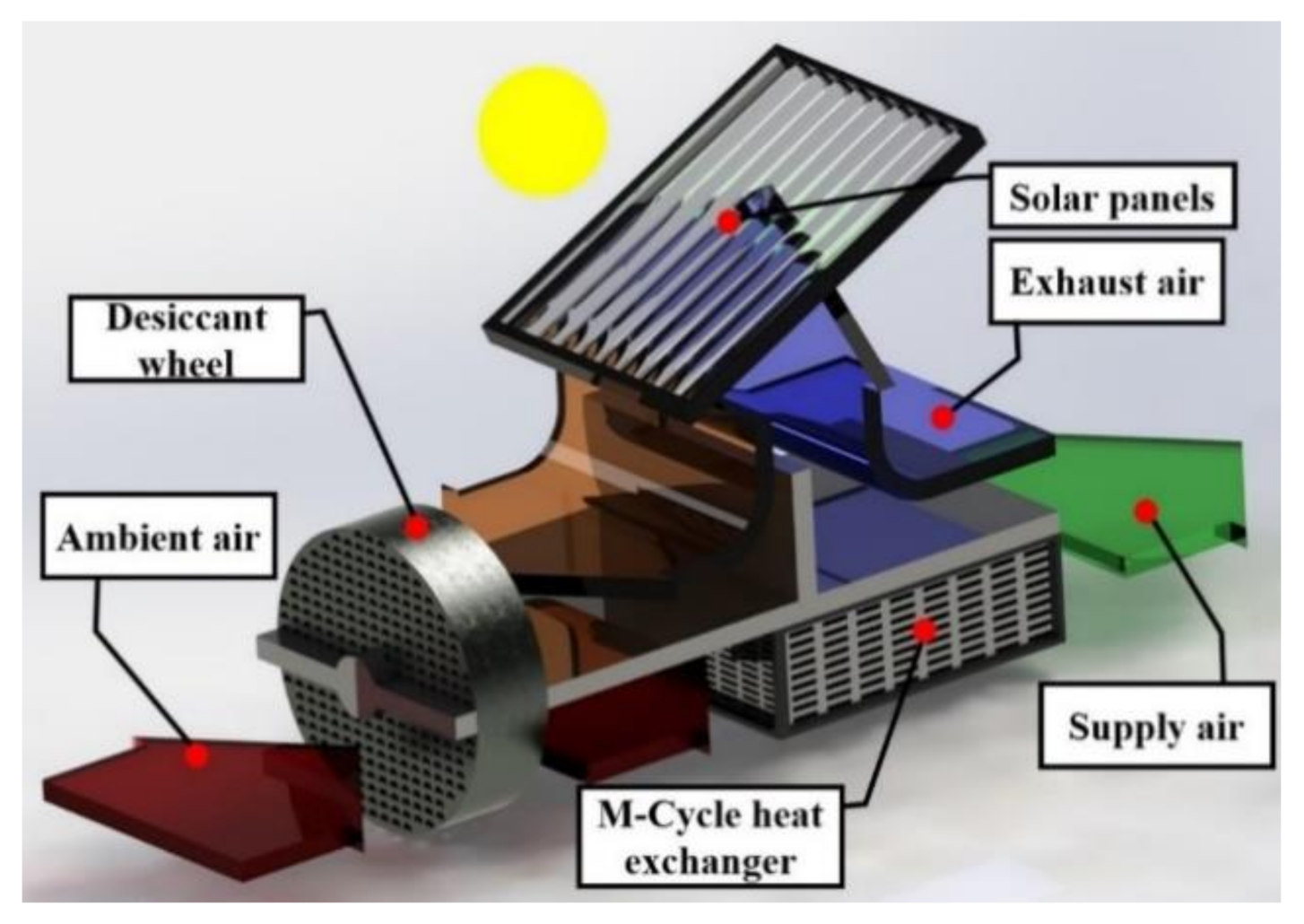
One of the solutions which is considered as the most promising for moderate and humid climates are desiccant systems based on the combination of a desiccant unit (solid or liquid) and indirect evaporative cooler. The desiccant device dehumidifies the air, and an indirect evaporative air cooler cools the air to the appropriate temperature level without adding any moisture. The key performance indicator describing desiccant cooling systems is thermal COP (defined as an amount of cooling capacity obtained by the unit divided by required heating capacity). The heating source is crucial to create an environmentally friendly cooling system. In the case of a desiccant cooling system, the heat source is needed to regenerate the desiccant. In Figure 5, a desiccant cooling system equipped with a M-Cycle heat exchanger (DPIEC) and solar collectors as a heat source is presented. It needs to be mentioned that waste heat, geothermal energy, or heat captured by a heat pump may be utilized to regenerate the desiccant. The key performance indicator of the system which utilizes heat to regenerate the desiccant is thermal coefficient of performance (COP) and seasonal coefficient of performance (SCOP):
—system cooling capacity, kW
—thermal power consumed for regeneration the desiccant, kW
Due to this fact, one of the major challenges for the desiccant—evaporative air-conditioning systems—is an ability to achieve high values of thermal COP. Higher thermal COP means higher application potential and lower operational costs. The problem with achieving high thermal COP is that it is often connected with creating very complicated systems (including multistage, a solar-assisted heating system, multiple heat recovery exchangers, cooling towers etc.). In the case of conventional desiccant cooling systems, the end-point air treatment is connected with airflow humidification in direct evaporative coolers. In the case of indirect evaporative heat exchangers, the same required parameters of the supply air can be reached, but, taking into account that air is cooled sensibly (without moisture content rising), a significantly lower air dehumidification is required in the desiccant wheel. It is the main premise to develop desiccant systems based on the M-Cycle indirect evaporative coolers [50]. In this paper, several recent publications that take into account the use of an intermediate evaporative exchanger in sorption systems are presented. For example, Delfani et al. [51] used computer software to perform numerical simulations of different solar desiccant cooling systems integrated with M-Cycle cooler and evaporative cooler. The results show that for considered climatic conditions (moderate and humid, hot and semi-humid and hot and humid), the solar desiccant cooling systems integrated with the M-Cycle show better cooling performance than the system equipped with the typical evaporative cooler. One of the solutions which is considered as most promising for moderate and humid climate are desiccant systems, based on the combination of a desiccant unit (solid or liquid) and an indirect evaporative air cooler (system reaches the average COPth = 0.728).
Desiccant cooling systems in different configurations with an indirect evaporative air cooling have been investigated by many authors in the past. Kashif Shahzad et al. [52] compared a solid desiccant dehumidifier integrated with a cross flow Maisotsenko cycle heat and mass exchanger (HMX) with a traditional desiccant air conditioning system integrated with a direct evaporative cooler under different operating conditions and the same process and return airflow rates. It was found out that for the same supply airflow and regenerative airflow parameters, the first system was approximately 60–65% more efficient than the second one. Comino et al. [53] determined an annual energy consumption of a hybrid system (composed of desiccant wheel and indirect evaporative cooler), in comparison to direct expansion conventional system. The hybrid system shows a significant energy saving, up to 46.8%, which was shown in simulations results. Chen et al. [54] studied a liquid desiccant dehumidifier cooperating with a regenerative indirect evaporative cooler. Energy for the regeneration process was tapped from solar collectors. The results showed that the optimal extraction for this system ratio is 0.3. Depending on inlet air conditions, this system achieves an energy saving ratio from 22.4% to 53.2%. Lin et al. [55] proposed a hybrid membrane, liquid desiccant dehumidification, and dew point evaporative cooling system. It consists of a cross-flow membrane liquid desiccant dehumidifier and a counter-flow dew point evaporative cooler. They published the experiment results and developed a mathematical model of the system. Gadalla et al. [56] investigated the performance of a two-stage solar desiccant air-conditioning systems equipped with dew point indirect evaporative coolers (DPIEC) for hot and humid climates. They used multistage dehumidification with two desiccant wheels and cooling processes with air-to-air and DPIEC to improve the average system COP which reached 1.77 during electricity load peak hours. They found out that it is possible to minimize required solar heating during midday at noon. Chaudhary et al. [57] experimentally analyzed a solar-assisted solid desiccant cooling system integrated with one DPIEC exchanger. The analysis of the system was performed for different days of the summer season. The COP of this system varies between 0.65 and 1.17. Comino et al. [53] focused on determining mainly the annual electricity consumption and seasonal coefficient of performance of a hybrid air conditioning system with a desiccant wheel and indirect evaporative cooler for 6 climate zones. The simulation results show that the system analyzed shows significant energy savings up to 46.8%, compared to a typical direct expansion system.
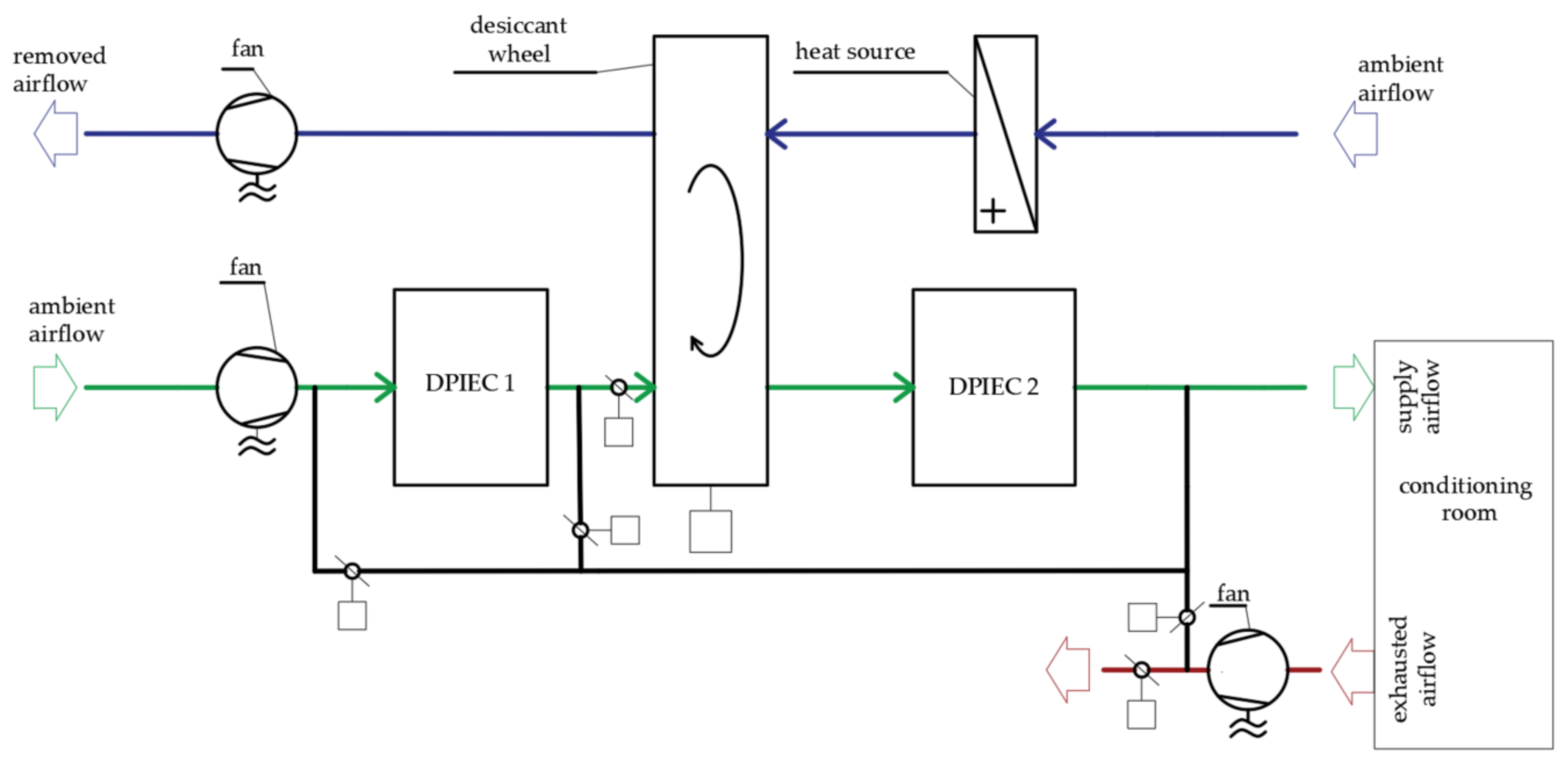
Due to the fact that sorption systems achieve low COPs, the researchers are constantly looking for opportunities to increase the efficiency of desiccant systems. In the field of desiccant cooling systems, the benefits of removing the heat of adsorption were noted. Literature studies show that it can be performed by cooling the air before the dehumidification process (see Figure 6) [58] or by cooling the desiccant [59].
Chen et al. [60] developed the performance of a silica gel/polymer composite desiccant wheel regenerated by the heat released from the heat pump. They proposed a desiccant air conditioning system with the evaporator before the desiccant wheel, to provide the initial dehumidification and pre-cooling of the ambient air. The results show that under the same conditions, a composite desiccant in a heat pump system outperformed the silica-gel-based system by 130% and consumed less power than traditional desiccant systems. Zhou et al. [61] studied the design and analyzed the performance of a novel tube-in-shell internally water-cooled desiccant wheel. Experiments were performed in order to validate the mathematical model. The results show that isothermal performance of the desiccant wheel can be achieved. Moreover, the improvement of a dehumidification process is significant, equaling 48% as compared with a conventional adiabatic desiccant wheel using a super-absorbent polymer as the desiccant material in a desiccant wheel. Chen and Tan [62] presented an air conditioning system integrated with a desiccant wheel and high-temperature chilled water from a natural cold source. They developed the mathematical model of the system, while system components were validated experimentally. The system shows more efficient energy performance than a conventional solar desiccant wheel air conditioning system in high, moderate, and low humidity climate conditions. Mrinal et al. [59,63] found the solid-desiccant system that utilizes low grade heat while the heat of sorption is rejected using water cooled in a cooling tower. They also analyzed system cooperation with cross-flow DPIEC and regenerative DPIEC. Pandelidis et al. [58] proposed a multi-stage desiccant indirect evaporative cooling system. The system is based on the ambient airflow precooling before the dehumidification process. It allows the COP values to be obtained up to 4.5 for specific operating conditions.
5. Discussion and Summary
The literature review showed different directions of research in dew point indirect evaporative cooling technology. Some system performance indicators, like dew point effectiveness and wet bulb effectiveness, reach maximum values that are similar in different studies. The maximum dew point efficiency is almost 100% for specific conditions and exchanger specific parameters (see Table 5). Therefore, there has been more and more work that focuses on improvement of energy consumption or the quality of water distribution methods in exchangers. There are a few experimental works listed in Table 1, in which various exchanger geometries, water distribution systems, and materials are analyzed. The DPIEC wet bulb efficiency (e.g., = 53%, = 64.5%, = 76% presented in Table 2) of those devices is lower, hence these technologies need further improvements. Many numerical studies of evaporative exchangers for hot climates can be found in the literature (Table 5). Scientists have shown high DPIEC efficiency in hot climates. The electrical coefficient of performance (COPel) is an important indicator, which depends on the geometry of the exchanger and it reaches values equal to 60. The implementation of DPIEC in humid or moderate climates involves the expansion of the system, due to the necessity of latent loads assimilation in an additional device (e.g., desiccant wheel or vapor compression system). The least complicated way to use a dew point evaporative cooler is a hybrid system with a typical compressor system. In such systems, scientists have proved electricity savings resulting from such an operation. The amount of savings depends on the type of building and its location. For example, Yang showed savings of 42–64% for hot and dry climates. Duan showed savings of around 38% for a residential building for a warm and humid climate. Zanchini and Naldi showed savings of 38% for the humid climate in which the office building is located. Pandelidis showed a saving of 65% for the air conditioning system of a commercial facility located in a temperate climate. Analyzes, simulations, and optimization of such systems aim to obtain the highest possible energy savings. In the case of usage of evaporative exchangers in sorption systems, an important indicator is the thermal COP or SCOP (seasonal COP), which defines the effectiveness of the system. Scientists are aiming to increase the COP without complicating the system structure. Currently, the systems achieve mean SCOP values of about 2.5, while the maximum instantaneous COP values are 4.5. Table 5 and Table 6 present a summary of selected publications, in which the different climate conditions for system operation were considered. In recent years, most scientists perform numerical studies on the basis of models validated to the existing experimental data. It can also be seen that combined systems are analyzed rather for hot humid climates, hence it requires more advanced technology. This is due to the need for ambient air dehumidification, which cannot be achieved with only DPIEC application. Recent publications also confirm researchers’ commitment in optimization of indirect evaporative cooler devices and hybrid systems (Table 4). The variety of proposed methods can be observed. Overall, research on indirect evaporative cooling is not slowing down, therefore this technology is becoming a more and more promising alternative cooling technology.
From the literature review, it can be concluded that despite intensive research and development in the field of evaporative cooling, scientists will face some challenges:
- Arrangement of the structure and geometry of the channels in terms of optimal water distribution and even air distribution.
- Improvement of water distribution systems with an emphasis on developing research into dedicated materials for evaporative indirect exchangers.
- It is necessary to simplify the system construction as much as possible: sorption systems with evaporative cooling are complicated compared to compressor systems and have large dimensions, therefore they are expensive in terms of investment.
- No research on indirect room evaporative exchangers—decentralized systems.
- Conducting further research on increasing the thermal COP.
- Determining the thermal COP from the actual cooling capacity of the supply air (in relation to the parameters of the internal air), not from the cooling capacity of a device that cools the outdoor air to the supply air parameters.
- The high COP of sorption systems allows for creation of an alternative cooling system while COP is high; with a heat source such as a solar collector, it requires smaller dimensions. This results in lower investment costs and greater system application possibilities.
Author Contributions
Conceptualization, A.P. and W.W.; formal analysis, A.P.; investigation, A.P.; writing—original draft preparation, A.P. and W.W.; writing—review and editing, W.W.; visualization, A.P.; funding acquisition, A.P. All authors have read and agreed to the published version of the manuscript.
Funding
This research was funded by Polish National Centre for Research and Development, program Lider X, agreement number U/0180/666/2019.
Institutional Review Board Statement
Not applicable.
Informed Consent Statement
Not applicable.
Data Availability Statement
Not applicable.
Conflicts of Interest
The authors declare no conflict of interest.
References
- IEA. The Future of Cooling; IEA: Paris, France, 2018; Available online: https://www.iea.org/reports/the-future-of-cooling (accessed on 30 November 2020).
- IEA. Global Status Report for Buildings and Construction 2019; IEA: Paris, France, 2019; Available online: https://www.iea.org/reports/global-status-report-for-buildings-and-construction-2019 (accessed on 30 November 2020).
- Ray, W.T. Conditioning Liquids and Air and Other Gases. U.S. Patent 19,865,929, 1 January 1935. [Google Scholar]
- Maisotsenko, V.; Cimerzan, A.; Zexer, M.P.N. Air Cooling Device for Indirect Evaporative. Soviet Union Patent 979,796, 1976. (In Russian). [Google Scholar]
- Yang, Y.; Cui, G.; Lan, C.Q. Developments in evaporative cooling and enhanced evaporative cooling—A review. Renew. Sustain. Energy Rev. 2019, 113, 109230. [Google Scholar] [CrossRef]
- Mahmood, M.H.; Sultan, M.; Miyazaki, T.; Koyama, S.; Maisotsenko, V.S. Overview of the Maisotsenko cycle—A way to-wards dew point evaporative cooling. Renew. Sustain. Energy Rev. 2016, 66, 537–555. [Google Scholar] [CrossRef]
- Cuce, P.M.; Riffat, S. A state of the art review of evaporative cooling systems for building applications. Renew. Sustain. Energy Rev. 2016, 54, 1240–1249. [Google Scholar] [CrossRef]
- Pandelidis, D.; Anisimov, S. Mathematical Modeling of the M-Cycle Heat and Mass Exchanger Used in Air Conditioning Systems. Ph.D. Thesis, Wrocław University of Science and Technology, Wrocław, Poland, 2016. [Google Scholar]
- De Antonellis, S.; Cignatta, L.; Facchini, C.; Liberati, P. Effect of heat exchanger plates geometry on performance of an indirect evaporative cooling system. Appl. Therm. Eng. 2020, 173, 115200. [Google Scholar] [CrossRef]
- Xu, P.; Ma, X.; Zhao, X.; Fancey, K. Experimental investigation of a super performance dew point air cooler. Appl. Energy 2017, 203, 761–777. [Google Scholar] [CrossRef]
- Meng, D.; Lv, J.; Chen, Y.; Li, H.; Ma, X. Visualized experimental investigation on cross-flow indirect evaporative cooler with condensation. Appl. Therm. Eng. 2018, 145, 165–173. [Google Scholar] [CrossRef]
- Al-zubaydi, A.Y.T.; Hong, G. Experimental study of a novel water-spraying configuration in indirect evaporative cooling. Appl. Therm. Eng. 2019, 151, 283–293. [Google Scholar] [CrossRef]
- Jia, L.; Liu, J.; Wang, C.; Cao, X.; Zhang, Z. Study of the thermal performance of a novel dew point evaporative cooler. Appl. Therm. Eng. 2019, 160, 114069. [Google Scholar] [CrossRef]
- Zhao, X.; Liu, S.; Riffat, S. Comparative study of heat and mass exchanging materials for indirect evaporative cooling systems. Build. Environ. 2008, 43, 1902–1911. [Google Scholar] [CrossRef]
- Duan, Z. Investigation of a Novel Dew Point Indirect Evaporative Air Conditioning System for Buildings. Ph.D. Thesis, University of Nottingham, Nottingham, UK, 2011. [Google Scholar]
- Xu, P.; Ma, X.; Zhao, X.; Fancey, K.S. Experimental investigation on performance of fabrics for indirect evaporative cooling applications. Build. Environ. 2016, 110, 104–114. [Google Scholar] [CrossRef]
- Doğramacı, P.A.; Aydın, D. Comparative experimental investigation of novel organic materials for direct evaporative cooling applications in hot-dry climate. J. Build. Eng. 2020, 30, 101240. [Google Scholar] [CrossRef]
- Niyomvas, B.; Potakarat, B. Performance Study of Cooling Pads. Adv. Mater. Res. 2013, 664, 931–935. [Google Scholar] [CrossRef]
- Al-Sulaiman, F.A. Evaluation of the performance of local fibers in evaporative cooling. Energy Convers. Manag. 2002, 43, 2267–2273. [Google Scholar] [CrossRef]
- Lee, J.; Lee, D.-Y. Experimental study of a counter flow regenerative evaporative cooler with finned channels. Int. J. Heat Mass Transf. 2013, 65, 173–179. [Google Scholar] [CrossRef]
- Moshari, S.; Heidarinejad, G. Analytical estimation of pressure drop in indirect evaporative coolers for power reduction. Energy Build. 2017, 150, 149–162. [Google Scholar] [CrossRef]
- Wan, Y.; Lin, J.; Jon, K.; Ren, C. Similarity analysis and comparative study on the performance of counter-flow dew point evaporative coolers with experimental validation. Energy Convers. Manag. 2018, 169, 97–110. [Google Scholar] [CrossRef]
- Lin, J.; Thuan, D.; Wang, R.; Jon, K. On the fundamental heat and mass transfer analysis of the counter- fl ow dew point evaporative cooler. Appl. Energy 2018, 217, 126–142. [Google Scholar] [CrossRef]
- Sadighi Dizaji, H.; Hu, E.J.; Chen, L. A comprehensive review of the Maisotsenko-cycle based air conditioning systems. Energy 2018, 156, 725–749. [Google Scholar] [CrossRef] [Green Version]
- Pakari, A.; Ghani, S. Comparison of 1D and 3D heat and mass transfer models of a counter flow dew point evaporative cooling system: Numerical and experimental study. Int. J. Refrig. 2019, 99, 114–125. [Google Scholar] [CrossRef]
- Pakari, A.; Ghani, S. Regression models for performance prediction of counter flow dew point evaporative cooling systems. Energy Convers. Manag. 2019, 185, 562–573. [Google Scholar] [CrossRef]
- Wan, Y.; Lin, J.; Chua, K.J.; Ren, C. A new method for prediction and analysis of heat and mass transfer in the counter-flow dew point evaporative cooler under diverse climatic, operating and geometric conditions. Int. J. Heat Mass Transf. 2018, 127, 1147–1160. [Google Scholar] [CrossRef]
- Badiei, A.; Akhlaghi, Y.; Zhaoa, X.; Li, J.; Yi, F.; Wang, Z. Can whole building energy models outperform numerical models, when forecasting performance of indirect evaporative cooling systems? Energy Convers. Manag. 2020, 213, 112886. [Google Scholar] [CrossRef]
- Baakeem, S.S.; Orfi, J.; Mohamad, A.A.; Bawazeer, S.A. The possibility of using a novel dew point air cooling system (M-Cycle) for A/C application in Arab Gulf Countries. Build. Environ. 2019, 148, 185–197. [Google Scholar] [CrossRef]
- Guo, C.; Liu, Q.; Zheng, B.; You, Y.; Li, Y. Development of model based on condensation area ratio and effect on heat transfer capacity of indirect evaporative cooling. Appl. Therm. Eng. 2020, 164, 114557. [Google Scholar] [CrossRef]
- Min, Y.; Chen, Y.; Yang, H. Numerical study on indirect evaporative coolers considering condensation: A thorough compar-ison between cross flow and counter flow. Int. J. Heat Mass Transf. 2019, 131, 472–486. [Google Scholar] [CrossRef]
- Pandelidis, D.; Cichoń, A.; Pacak, A.; Anisimov, S.; Drąg, P. Performance comparison between counter- and cross-flow indirect evaporative coolers for heat recovery in air conditioning systems in the presence of condensation in the product air channels. Int. J. Heat Mass Transf. 2019, 130, 757–777. [Google Scholar] [CrossRef]
- Zheng, B.; Guo, C.; Chen, T.; Shi, Q.; Lv, J.; You, Y. Development of an experimental validated model of cross-flow indirect evaporative cooler with condensation. Appl. Energy 2019, 252, 113438. [Google Scholar] [CrossRef]
- Pandelidis, D.; Cichoń, A.; Pacak, A.; Drąg, P.; Drąg, M.; Worek, W.; Cetin, S. Performance study of the cross-flow Mai-sotsenko cycle in humid climate conditions. Int. Commun. Heat Mass Transf. 2020, 115, 104581. [Google Scholar] [CrossRef]
- Liu, Y.; Akhlaghi, Y.G.; Zhao, X.; Li, J. Experimental and numerical investigation of a high-efficiency dew-point evaporative cooler. Energy Build. 2019, 197, 120–130. [Google Scholar] [CrossRef] [Green Version]
- Sohani, A.; Sayyaadi, H.; Mohammadhosseini, N. Comparative study of the conventional types of heat and mass exchangers to achieve the best design of dew point evaporative coolers at diverse climatic conditions. Energy Convers. Manag. 2018, 158, 327–345. [Google Scholar] [CrossRef]
- Sohani, A.; Sayyaadi, H.; Zeraatpisheh, M. Optimization strategy by a general approach to enhance improving potential of dew-point evaporative coolers. Energy Convers. Manag. 2019, 188, 177–213. [Google Scholar] [CrossRef]
- Wang, L.; Zhan, C.; Zhang, J.; Zhao, X. The energy and exergy analysis on the performance of counter-flow heat and mass exchanger for M-cycle indirect evaporative cooling. Therm. Sci. 2019, 23, 153. [Google Scholar] [CrossRef]
- Jafarian, H.; Sayyaadi, H.; Torabi, F. Modeling and optimization of dew-point evaporative coolers based on a developed GMDH-type neural network. Energy Convers. Manag. 2017, 143, 49–65. [Google Scholar] [CrossRef]
- Chen, Y.; Yang, H.; Luo, Y. Parameter sensitivity analysis and configuration optimization of indirect evaporative cooler (IEC) considering condensation. Appl. Energy 2017, 194, 440–453. [Google Scholar] [CrossRef]
- Chua, K.J.; Wang, R.; Li, C.; Wang, S.; Long, J.; Chua, K.J. Towards a thermodynamically favorable dew point evaporative cooler via optimization. Energy Convers. Manag. 2020, 203, 112224. [Google Scholar] [CrossRef]
- Akhlaghi, Y.G.; Badiei, A.; Zhao, X.; Aslansefat, K.; Xiao, X.; Shittu, S.; Ma, X. A constraint multi-objective evolu-tionary optimization of a state-of-the-art dew point cooler using digital twins. Energy Convers. Manag. 2020, 211, 112772. [Google Scholar] [CrossRef]
- Golizadeh Akhlaghi, Y.; Aslansefat, K.; Zhao, X.; Sadati, S.; Badiei, A.; Xiao, X.; Shittu, S.; Fan, Y.; Ma, X. Hourly performance forecast of a dew point cooler using explainable Artificial Intelligence and evolutionary optimisations by 2050. Appl. Energy 2021, 281, 116062. [Google Scholar] [CrossRef]
- Zanchini, E.; Naldi, C. Energy saving obtainable by applying a commercially available M-cycle evaporative cooling system to the air conditioning of an office building in North Italy. Energy 2019, 179, 975–988. [Google Scholar] [CrossRef]
- Duan, Z.; Zhao, X.; Liu, J.; Zhang, Q. Dynamic simulation of a hybrid dew point evaporative cooler and vapour compression refrigerated system for a building using EnergyPlus. J. Build. Eng. 2019, 21, 287–301. [Google Scholar] [CrossRef]
- Cui, X.; Islam, M.R.; Chua, K.J. An experimental and analytical study of a hybrid air-conditioning system in buildings resid-ing in tropics. Energy Build. 2019, 201, 216–226. [Google Scholar] [CrossRef]
- Pandelidis, D.; Niemierka, E.; Pacak, A.; Jadwiszczak, P.; Cichoń, A.; Drąg, P.; Worek, W.; Cetin, S. Performance study of a novel dew point evaporative cooler in the climate of central Europe using building simulation tools. Build. Environ. 2020, 181, 107101. [Google Scholar] [CrossRef]
- Katramiz, E.; Al Jebaei, H.; Alotaibi, S.; Chakroun, W.; Ghaddar, N.; Ghali, K. Sustainable cooling system for Kuwait hot climate combining diurnal radiative cooling and indirect evaporative cooling system. Energy 2020, 213, 119045. [Google Scholar] [CrossRef]
- Yang, Y.; Ren, C.; Wang, Z.; Luo, B. Theoretical performance analysis of a new hybrid air conditioning system in hot-dry cli-mate. Int. J. Refrig. 2020, 116, 96–107. [Google Scholar] [CrossRef]
- Pacak, A.; Cichoń, A.; Pandelidis, D.; Anisimov, S. Impact of indirect evaporative air cooler type on the performance of desic-cant systems. In Proceedings of the 10th Conference on Interdisciplinary Problems in Environmental Protection and Engineering (EKO-DOK 2018), Polanica-Zdrój, Poland, 16–18 April 2018; Kaźmierczak, B., Kutyłowska, M., Piekarska, K., Jadwiszczak, P., Eds.; E3S Web of Conferences. EDP Sciences: Les Ulis, France, 2018; Volume 44. [Google Scholar]
- Delfani, S.; Karami, M. Transient simulation of solar desiccant/M-Cycle cooling systems in three different climatic conditions. J. Build. Eng. 2020, 29, 101152. [Google Scholar] [CrossRef]
- Shahzad, M.K.; Ali, M.; Sheikh, N.A.; Chaudhary, G.Q.; Khalil, M.S.; Rashid, T.U. Experimental evalu-ation of a solid desiccant system integrated with cross flow Maisotsenko cycle evaporative cooler. Appl. Therm. Eng. 2018, 128, 1476–1487. [Google Scholar] [CrossRef]
- Comino, F.; De Adana, M.R.; Peci, F. Energy saving potential of a hybrid HVAC system with a desiccant wheel activated at low temperatures and an indirect evaporative cooler in handling air in buildings with high latent loads. Appl. Therm. Eng. 2018, 131, 412–427. [Google Scholar] [CrossRef]
- Chen, Y.; Yang, H.; Luo, Y. Investigation on solar assisted liquid desiccant dehumidifier and evaporative cooling system for fresh air treatment. Energy 2018, 143, 114–127. [Google Scholar] [CrossRef]
- Lin, J.; Huang, S.-M.; Wang, R.; Chua, K.J. Thermodynamic analysis of a hybrid membrane liquid desiccant dehumidification and dew point evaporative cooling system. Energy Convers. Manag. 2018, 156, 440–458. [Google Scholar] [CrossRef]
- Gadalla, M.; Saghafifar, M. Performance assessment and transient optimization of air precooling in multi-stage solid desic-cant air conditioning systems. Energy Convers. Manag. 2016, 119, 187–202. [Google Scholar] [CrossRef]
- Chaudhary, G.Q.; Ali, M.; Sheikh, N.A.; Gilani, S.I.U.H.; Khushnood, S. Integration of solar assisted solid desiccant cooling system with efficient evaporative cooling technique for separate load handling. Appl. Therm. Eng. 2018, 140, 696–706. [Google Scholar] [CrossRef]
- Pandelidis, D.; Pacak, A.; Cichoń, A.; Anisimov, S.; Drąg, P.; Vager, B.; Vasilijev, V. Multi-stage desiccant cooling system for moderate climate. Energy Convers. Manag. 2018, 177, 77–90. [Google Scholar] [CrossRef]
- Jagirdar, M.; Lee, P.S. Mathematical modeling and performance evaluation of a desiccant coated fin-tube heat exchanger. Appl. Energy 2018, 212, 401–415. [Google Scholar] [CrossRef]
- Chen, C.-C.; Hsu, C.-Y.; Chiang, Y.-C.; Chen, S.-L. Silica gel/polymer composite desiccant wheel combined with heat pump for air-conditioning systems. Energy 2016, 94, 87–99. [Google Scholar] [CrossRef]
- Zhou, X.; Goldsworthy, M.; Sproul, A.B. Performance investigation of an internally cooled desiccant wheel. Appl. Energy 2018, 224, 382–397. [Google Scholar] [CrossRef]
- Chen, L.; Tan, Y. The performance of a desiccant wheel air conditioning system with high-temperature chilled water from natural cold source. Renew. Energy 2020, 146, 2142–2157. [Google Scholar] [CrossRef]
- Jagirdar, M.; Pandelidis, D.; Pacak, A.; Worek, W.; Cetin, S. Performance evaluation of an air conditioning system based on quasi isothermal dehumidifcation. Energy Convers. Manag. 2020, 217, 113009. [Google Scholar] [CrossRef]
- Comino, F.; González, J.C.; Navas-Martos, F.J.; de Adana, M.R. Experimental energy performance assessment of a solar desiccant cooling system in Southern Europe climates. Appl. Therm. Eng. 2020, 165, 114579. [Google Scholar] [CrossRef]
Figure 1.
Division of research areas of evaporative cooling included in this study.

Figure 2.
Division of research areas of evaporative cooling included in this study.

Figure 3.
Indirect evaporative coolers [8]: (a) Counter-flow indirect evaporative cooling (IEC). (b) Dew point cross-flow IEC. (c) Regenerative dew point IEC. (d) Cross flow IEC.
Figure 3.
Indirect evaporative coolers [8]: (a) Counter-flow indirect evaporative cooling (IEC). (b) Dew point cross-flow IEC. (c) Regenerative dew point IEC. (d) Cross flow IEC.


Figure 4.
Hybrid system scheme.

Figure 5.
Typical solar desiccant cooling system scheme [8].
Figure 5.
Typical solar desiccant cooling system scheme [8].

Figure 6.
Desiccant cooling system scheme with ambient air precooling.


Table 1.
Key strings used for the literature search at Scopus (years 2017–2021).
| Search Number | Key Words | Number of Records |
|---|---|---|
| Search 1 | dew AND point AND evaporative AND cooling | 105 |
| Search 2 | M-cycle AND evaporative AND cooling | 44 |
| Search 3 | Maistotsenko-Cycle AND evaporative AND cooling | 43 |
| Search 4 | desiccant AND indirect AND evaporative AND cooling | 44 |
| Search 5 | hybrid AND indirect AND evaporative AND cooling | 367 |
Table 2.
Experiments including development of dew point indirect evaporative coolers (DPIEC) structure development.
Table 2.
Experiments including development of dew point indirect evaporative coolers (DPIEC) structure development.
| Novelty of Technology | Performance | Reference |
|---|---|---|
| Different IEC geometry and flow arrangement | = 53% | Antonellis [9] |
| Super-performance hydrophilic material layer | = 114%, = 75% | Xu et al. [10] |
| Presence of condensation in cross-flow exchanger | = 64.5% | Meng et al. [11] |
| Different water spraying configurations | = 76% | Al-zubaydi et al. [12] |
| Exchangers made of polystyrene and nylon fiber | = 78.4% | Jia et al. [13] |
| Analyzed different materials for DPIEC | - | Zhao et al. [14] |
| Water-absorbing experiment | - | Duan [15] |
| Analyzed different cooling pads | - | Xu et al. [16], Doğramacı et al. [17], Al-Sulaiman [19] |
Table 3.
Modelling of the DPIEC performance.
| Study Methods | Experiment (Y/N) | Novelty of Technology | Performance (Maximum Effectiveness) | Reference |
|---|---|---|---|---|
| Analytical | N | Different fin heights included | = 120% | [21] |
| CFD | Y | Different water film distribution | = 110% = 78% | [22] |
| CFD | Y | Nusselt number and Sherwood number are examined | - | [23] |
| Statistical | Y | Simple predicting the DPIEC performance | = 120% | [25] |
| = 118% | [26] | |||
| NTU-Le-R method and CFD model | Y | Presented a new method to precisely obtain the transfer coefficient | - | [27] |
| Statistical and building energy model | Y | The detailed investigation of the cooling systems within a building context | = 115% = 85% | [28] |
| ε-NTU method | N | The condensation phenomenon included and analyzed | = 84% | [30] |
| ε-NTU method | Y | = 84% | [31] | |
| ε-NTU method | Y | = 100% = 96% | [32] |
Table 4.
Counter-flow DPIEC optimization. SOO, single-objective optimization; MOO, multi-objective optimization; COP, coefficient of performance.
Table 4.
Counter-flow DPIEC optimization. SOO, single-objective optimization; MOO, multi-objective optimization; COP, coefficient of performance.
| Method | Optimized Results | Objective Functions | Reference |
|---|---|---|---|
| SOO | Water and air flow arrangement | wet-bulb efficiency, COP | [35] |
| MOO | Operational and geometric characteristics of the cooler | Life-cycle cost, annual water consumption, annual COP | [36] |
| MOO | Inlet air velocity and working to air ratio (geometry optimized in previous study) | Life-cycle cost, annual water consumption, annual COP | [37] |
| MOO | Velocity in dry channels, channel length, working to intake air ratio | Entropy production number | [38] |
| MOO | Channel length, channel gap, inlet air velocity and return to intake air ratio (for diverse climatic conditions) | Specific area, COP | [39] |
| SOO | Channel gap, cooler height, NTU | Wet-bulb efficiency, enlargement coefficient, synthetic index | [40] |
| MOO | Optimal channel length and working ratio for different scenarios | Dew point effectiveness, COP, cooling capacity | [41] |
| MOO | Operating and design parameters | COP, wet-bulb efficiencies, the surface area | [42] |
| SOO | Construction costs | Cooling efficiency | [43] |
Table 5.
Studies of systems using DPIEC in hot and dry.
| System | Region | Experiment | Numerical | Performance | Reference |
|---|---|---|---|---|---|
| (A) DPIEC | Arab Gulf cities | no | yes | [29] | |
| (A) DPIEC | e.g., Riyadh, South Arabia | no | yes | [36] | |
| (B) DPIEC (with heat and mass exchanger) | e.g., Riyadh, South Arabia | no | yes | [28] | |
| (B) DPIEC and hydronic radiative cooling | Kuwait | no | yes | 53.4% reduction of electrical energy | [48] |
| (B) DPIEC and vapor compression system | China | no | yes | 42.5% to 64.0% of energy savings | [49] |
| (C1) Solar desiccant cooling system | Martos, Spain | yes | no | SCOP = 2.0 | [64] |
| (C2) Solid desiccant cooling system | e.g., Tunis | no | yes | SCOP = 2.1 energy savings 41.9% | [53] |
Table 6.
Studies of systems using DPIEC in hot and humid regions.
| Region | Experiment | Numerical | Performance | Reference | |
|---|---|---|---|---|---|
| (B) DPIEC (with heat and mass exchanger) | e.g., Beijing, China | no | yes | [28] | |
| (B) DPIEC and vapor compression system | North Italy | partial | yes | 37.6% of energy savings | [44] |
| (B) DPIEC and vapor compression system | Beijing, China | no | yes | 38.2% of energy savings | [45] |
| (C1) Solar desiccant cooling system | e.g., Buszehr, Iran | no | yes | [51] | |
| (C2) Solid desiccant cooling system | Simulated range | yes | no | [52] | |
| (C2) Solid desiccant cooling | e.g., Singapure | no | yes | SCOP = 2.8 energy savings 43.5% | [53] |
| (C2) Solid desiccant cooling | United Arab Emirates | no | yes | [56] | |
| (C1) Solar desiccant cooling system | Taxila, Pakistan | yes | no | [57] | |
| (C3) Liquid desiccant cooling system and vapor compression system | Simulated | no | yes | Energy savings 22.4% to 53.2% | [54] |
| (C3) Liquid desiccant hybrid membrane cooling system | Simulated | yes | yes | 122% = 81% | [55] |
Publisher’s Note: MDPI stays neutral with regard to jurisdictional claims in published maps and institutional affiliations. |
© 2021 by the authors. Licensee MDPI, Basel, Switzerland. This article is an open access article distributed under the terms and conditions of the Creative Commons Attribution (CC BY) license (http://creativecommons.org/licenses/by/4.0/).
Share and Cite
MDPI and ACS Style
Pacak, A.; Worek, W. Review of Dew Point Evaporative Cooling Technology for Air Conditioning Applications. Appl. Sci. 2021, 11, 934. https://0-doi-org.brum.beds.ac.uk/10.3390/app11030934
AMA Style
Pacak A, Worek W. Review of Dew Point Evaporative Cooling Technology for Air Conditioning Applications. Applied Sciences. 2021; 11(3):934. https://0-doi-org.brum.beds.ac.uk/10.3390/app11030934
Chicago/Turabian StylePacak, Anna, and William Worek. 2021. "Review of Dew Point Evaporative Cooling Technology for Air Conditioning Applications" Applied Sciences 11, no. 3: 934. https://0-doi-org.brum.beds.ac.uk/10.3390/app11030934
Note that from the first issue of 2016, this journal uses article numbers instead of page numbers. See further details here.