
Influence of Cracking on the Durability of Reinforced Concrete with Carbon Nanotubes


1
CERIS, Department of Civil Engineering, Architecture and Georresources, Instituto Superior Técnico, University of Lisbon, Av. Rovisco Pais, 1049-001 Lisbon, Portugal
2
Department of Highway & Bridge Engineering, Technical Engineering College, Erbil Polytechnic University, Erbil 44001, Iraq
3
Scientific Research and Development Center, Nawroz University, Duhok 42001, Kurdistan-Region, Iraq
*
Author to whom correspondence should be addressed.
Appl. Sci. 2021, 11(4), 1672; https://0-doi-org.brum.beds.ac.uk/10.3390/app11041672
Submission received: 21 January 2021
/
Revised: 5 February 2021
/
Accepted: 7 February 2021
/
Published: 12 February 2021
(This article belongs to the Special Issue Concrete and Mortar with Non-conventional Materials)
Abstract
:This study focuses on the influence of natural and artificially induced cracks on the durability of concrete reinforced with carbon nanotubes (CNT). Pre-cracked concrete mixes, unreinforced or reinforced with 0.1% CNT, are characterized in terms of capillary absorption, carbonation, and chloride penetration resistance, and compared to the uncracked reference concrete. The mechanical strength and durability properties were improved in uncracked CNT-reinforced concrete, without significantly affecting its density and workability. The efficiency of CNT was higher when the concrete was previously subjected to drying conditions. For all tested properties, the incorporation of CNT was effective in reducing the influence of artificial and natural cracks on concrete durability. The main contribution of CNT occurred in the crack surrounding region. Depending on the analyzed property and cracking conditions, the significant reduction of durability in cracked concrete may be 10–30% attenuated when CNT is incorporated. The effect was more pronounced in mechanically induced natural cracks, where CNT may better participate in their vicinity.
1. Introduction
Concrete is a quasi-brittle material highly prone to crack formation throughout its service life [1,2]. The reasons behind crack appearance in concrete include poor design, mechanical actions, hygrothermal changes, shrinkage, and others [3,4]. Cracks tend to form in concrete when the internal tensile stresses surpass its optimum tensile strength. The newly created paths may increase concrete permeability to water and deleterious agents, negatively affecting its durability. Various investigations have been carried out to study the effect of cracks on the durability behavior of conventional concrete [5,6,7,8,9,10]. Studies involving pre-cracking via splitting tensile tests indicated that the permeability was significantly affected for crack widths over 0.05 mm [6,8], especially up to 0.2 mm [5,6]. For crack widths wider than 0.2 mm, the permeability increase continued but at a lower rate. In another study [11], considering concrete specimens with natural and artificial cracks, the coefficient of permeability increased parabolically with the crack width (0.1–0.5 mm).
Factors affecting the concrete penetrability include orientation, depth, and geometry of the cracks, which makes it difficult to precisely evaluate the cracking influence on the overall concrete durability. In order to overcome this issue, investigators have attempted to estimate threshold crack widths, above which, chloride and carbonation of cracked concrete is significantly increased [7,9,10,12]. Critical crack widths of 0.05–0.08 mm were determined for chloride diffusion in cracked concrete specimens [10,13]. In a study by Schutter et al. [5], the depth of chloride penetration and carbonation of concrete were related to the crack width through proposed expressions. Other investigators have related the crack width to CO2 diffusion ability [12], or connected the crack width to the carbonation depth with an S-shaped curve [7], where the carbonation is greatly increased up to an upper limit, above which the further increase of the crack width has lower influence on this property.
The rising demand for concrete and higher durability requirements increased the research efforts in order to enhance the performance of this material. An answer to the structural and durability challenges of concrete is the incorporation of reinforcing fibers in the cementitious matrix, aiming to improve the concrete ductility and control over cracks [14,15]. However, due to their size, the most common fibers are unable to act at a micro level, preventing small microcracks from becoming larger and propagating into macrocracks.
During the last decade, carbon nanotubes (CNT) have been studied as a reinforcement material for cement-based composites [16,17,18,19,20,21,22,23,24,25,26]. The growing interest in this field comes from the desire to modify the cement matrix at the scale of their main compounds, by taking advantage of the outstanding properties of CNT. On the one hand, CNT have ultra-high strength and stiffness, with Young’s modulus up to 1 TPa and exceptional tensile strength up to 100 GPa [27]. On the other hand, they have extremely high aspect ratios (1:1000) and surface area (up to 1000 m2/g), as well as very low density (1500 kg/m3). Therefore, CNT are ideal candidates for cement nano-reinforcement, being potentially able to retain the propagation of nano-cracks and improving some negative features of cement-based materials, such as the low tensile strength and low strain capacity. In fact, CNT have been proven to enhance the fracture properties and early age strain capacity of cement pastes and mortars, reducing or preventing crack initiation [25,26].
Due to their significant capillary forces, the small pores up to about 50 nm have a great impact in the shrinkage and creep of concrete, as well as on durability [28,29]. Due to their small dimensions, CNT are able to affect the concrete porous structure and work as fillers and nucleation sites, reducing the number of pores below 50 nm [30]. In fact, the incorporation of CNT in concrete is expected to essentially affect the source of time-dependent shrinkage and creep, by densifying the cement paste microstructure (nucleation and filler effect) and by controlling the propagation and development of microcracks (bridging effect) [18,23].
Regarding the characterization of CNT-reinforced cementitious materials, various studies have been carried out focusing on the physical, mechanical and durability characterizations of cement pastes and mortars [20,22,23,30], and few on those properties of CNT-reinforced concrete [16,17,18,21,24]. The studied properties of CNT-reinforced cementitious materials include compressive strength [16,17,18,19,20,21,22,23,24], flexural strength [17,19,20,23,24], splitting tensile strength [17], modulus of elasticity [17,18,22,23], ultrasonic pulse velocity [18,23], fracture toughness [17,23], steel-concrete bond [21], shrinkage [18,22,23], creep [18], microscopic analysis [17,18,19,20,22,23,24], capillary absorption [16,22,24], absorption by immersion [22,24], carbonation [24], chloride ion penetration [24], and oxygen permeability [16]. However, despite its relevance, to the best of the authors’ knowledge no study has been carried out on the durability of cracked CNT reinforced concrete.
In this study, the influence of natural and artificial induced cracks on the durability of concrete reinforced with CNT is investigated. Pre-cracked concrete mixes, unreinforced or reinforced with 0.1% CNT, are characterized and compared to the uncracked reference concrete in terms of their main fresh properties, mechanical strength and, especially, durability (capillary absorption, carbonation, and chloride attack).
2. Materials and Methods
2.1. Materials
One type of industrial multi-walled carbon nanotubes was selected to produce the CNT-reinforced concrete mixes. This type of CNT was supplied in aqueous suspension, with the commercial designation “TNIM8”. According to the supplier, the CNT were previously dispersed in water at CNT concentrations of 9%, using a polyethylene-based dispersant. Nevertheless, CNT were further dispersed according to the procedure indicated in Section 2.2, in order to more effectively break the bundles. The main properties of CNT provided by the supplier are listed in Table 1.
2.2. Concrete Production
Prior to their incorporation in concrete mixes, the CNT were dispersed by a combination of physical procedures, involving sonication and magnetic stirring of the aqueous suspension. The dispersion process was defined according to a previous study of the authors [17]. The procedure involved 45 min of sonication followed by 60 min of magnetic stirring with 40% of the concrete mixing water. This procedure was selected to obtain maximum level of dispersion without severely damaging the CNT.
Two concrete mixes were produced with the same water to cement ratios (w/c of 0.55); one CNT-reinforced concrete (CNTRC) and one plain concrete (PC) without CNT, for comparison purposes. The concrete compositions are presented in Table 3. The CNT content, of 0.1% by weight of cement, was defined considering the results of previous studies [20,22,23] regarding the mechanical characterization of cement pastes and mortars with 0.015–0.1% of the same type of CNT.
Concrete mixes were produced in a vertical shaft mixer with bottom discharge. The mixing procedure began with the addition of all the aggregates in descending order of its size and mixed for 3 min with 60% of the total mixing water. After this stage, the mixer was stopped for 1 min. The cement and the remaining 40% of water, with or without dispersed CNT, were then added to the mixture, which was mixed for further 4 min. In total, the mixing procedure lasted approximately 8 min. After mixing, the slump and fresh density were measured according to EN 12350-2 [32] and EN 12350-6 [33], respectively.
2.3. Sampling and Curing
The following specimens were casted for each mix: four 150 mm cubic specimens for compressive strength tests at 28 days, according to EN 12390-3 [34]; nine Ø100 × 200 mm cylindrical specimens for testing capillary absorption, carbonation, and chloride penetration tests, for uncracked and artificially cracked concrete; six 600 × 150 × 150 mm3 prisms to produce the 18 natural cracked specimens considered for the capillary absorption, carbonation, and chloride migration tests.
All specimens were demolded after 24 h of casting and kept for 7 days in a wet chamber with a temperature of 20 ± 2 °C and a relative humidity over 95%. After this, different curing conditions were considered depending on the experimental test. The cubic specimens for compressive strength tests and the cylindrical ones for chloride penetration tests were kept in the wet chamber until testing. The cylindrical specimens for capillary absorption tests were pre-conditioned according to RILEM TC116-PCD [35]: after the first 7 days in the wet chamber, the samples were sawn into smaller specimens of 50 mm thickness and then kept in a controlled dry chamber (temperature of 22 ± 2 °C and relative humidity of 50 ± 5%) for 7 days, followed by oven-drying at 60 °C for 13 days (the last 10 days sealed with a plastic film). The specimens for carbonation tests were pre-conditioned according to LNEC E391 [36], being water cured for 14 days and then placed in the dry chamber until testing. All specimens were left at ambient temperature for one day before testing. The prismatic specimens were cured in the wet chamber until 28 days, when they were subjected to natural cracking and core sampling according to Section 2.4.
2.4. Pre-Cracking Concrete
There are two distinct types of cracks that can be induced into concrete specimens: artificial and natural cracks. On the one hand, artificial cracks show more uniform characteristics, are easier to control the crack width and are more replicable. On the other hand, natural cracks with tortuous and non-uniform geometry may better simulate reality. However, the width and repeatability of natural cracks are challenging to control.
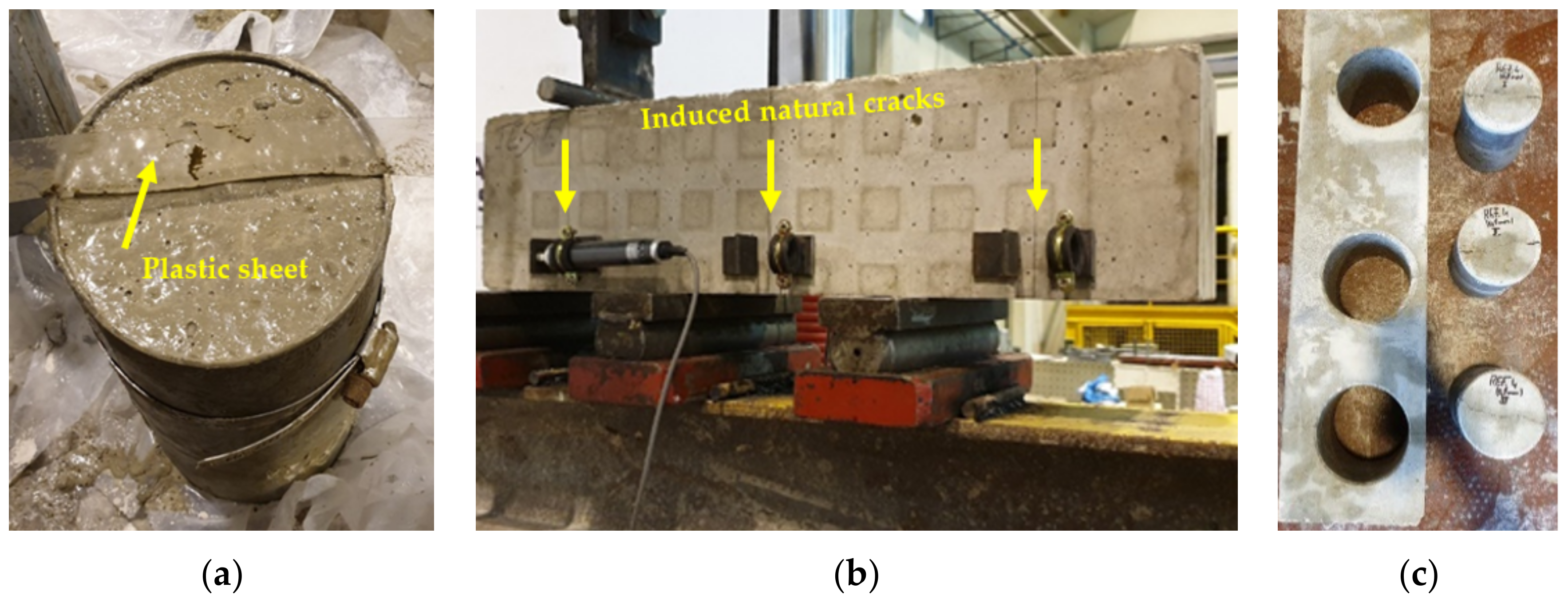
Artificial cracks were implemented using the notch method, in which a thin plastic sheet with 0.05 mm thickness was inserted in the sample, while the concrete was still fresh (Figure 1a). After about 5 h of concrete casting, the sheet was removed. The removal time was defined based on previous studies [37], allowing the easy extraction of the sheet, without damage or crack reclosing. In this study, to obtain the desired width of as low as 0.05 mm and get a final crack depth of about 10 mm, plastic sheets were inserted 20 mm deep into the concrete. The main disadvantage of this method is that the sheet induces a wall-effect and smooth cracked surface, which deviates from the real behavior of cracked concrete.
Natural cracks were generated on 600 × 150 × 150 mm3 prisms with 28 days, by means of a three-point controlled bending method (Figure 1b). To prevent the sudden failure and control the crack width, the prisms were reinforced with two Ø6 A500NR steel bars at the bottom. Two target crack widths were considered, 0.05 and 0.1 mm. Three beams were produced for each concrete composition and target crack width.
A hydraulic INSTRON press with 250 kN load capacity was adopted to locally induce the natural cracks. In each pre-cracked section, the crack width was controlled by a linear variable differential transformer with a 25 mm stroke, placed on both sides of the beam (Figure 1b). The stress and strain values were registered using an HBM Spider8 data logger. Loading and unloading cycles were implemented until the target crack width was reached after unloading. Three cores with Ø95 × 150 mm, centered with the induced cracks, were drilled from each beam (Figure 1c). Each core was then wrapped with a tight tape and sectioned into Ø95 × 50 mm samples destined for testing. Depending on the experimental test, these samples were then subjected to the curing conditions described in Section 2.3. However, as specimens were older and laterally sealed, the drying curing for capillary absorption tests was less effective. The experimental tests were carried out at 56 days. Due to the inherent difficulty of inducing natural cracks, the final crack width deviated from the target. For the intended target of 0.05 mm and 0.1 mm, the obtained crack width varied between 0.03–0.1 mm and 0.1–0.2 mm, respectively. This was measured before testing, using a digital microscope with up to 220× magnification.
2.5. Testing Procedeurs
2.5.1. Capillary Absorption
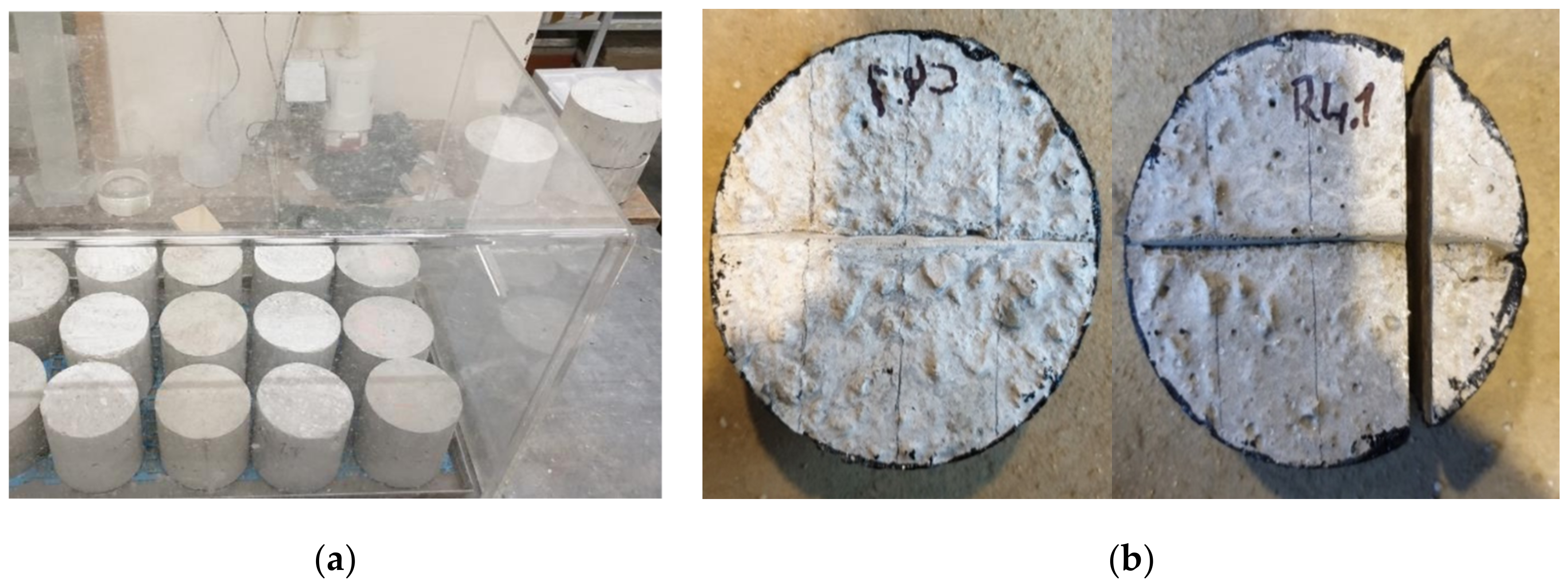
Capillary absorption was determined at 28 days in compliance with LNEC E393 [38]. The mass increase due to water absorption was measured as a function of time, after the bottom surface of the specimen was immersed in a 5 ± 1 mm of water (Figure 2a). The mass of the specimen was recorded at 10, 20, 30 min and 1, 3, 6, 24, and 72 h, after the initial contact with water. From the absorption curve plotted against the square root of time, the coefficients of absorption, Cabs,0–3h and Cabs,6–72h, were determined as equivalent to the slope of the linear regression line up to 3 h and between 6 and 72 h, respectively. Three specimens were tested per each composition and cracking type.
2.5.2. Carbonation Resistance
The accelerated carbonation test was carried out according to LNEC E391 [36]. After curing, the artificial cracked specimens (Ø100 × 50 mm) were painted in all surfaces except the cracked one, to ensure the unidirectional carbonation flow through the specimen. Then the specimens were placed in a carbonation chamber with 23 ± 3 °C, 60 ± 5% relative humidity and 5 ± 0.1% CO2, for 28, 56 and 90 days. The natural cracked specimens were sealed with tape around the lateral surface and at the bottom. The cracked surface was left unprotected. Afterwards, the specimens were moved to the same carbonation chamber and tested at 7 and 28 days. The specimens were first sectioned perpendicularly to the crack, then air dried for 24 h and placed back in the carbonation chamber. This procedure was carried out at each testing age, as exemplified in Figure 2b. The carbonation depth was measured after spraying a 0.2% phenolphthalein solution on the freshly broken surfaces. In cracked specimens, two different measures were taken, one in the cracked region and the other in the uncracked zone. One specimen per age was tested for each combination of composition and crack width. The carbonation coefficient, Kc, was obtained from the linear regression between the carbonation depth, xc, and the square root of time, t1/2, by applying the Fick’s first law of diffusion through Equation (1).
2.5.3. Chloride Penetration Resistance
The chloride penetration resistance was determined by the rapid chloride migration (RCM) test, according to LNEC E463 [39] and NTbuild492 [40], which provides a chloride ion migration diffusion coefficient (Dcl) under non-steady conditions. Three Ø100 × 50 mm cylindrical specimens were tested per each concrete composition. An external electrical potential was applied to force migration of chloride ions into the specimen, which was then split in two halves and sprayed with a silver nitrate solution. The chloride penetration depth was determined as the limit of the white silver chloride precipitation. Seven measures were taken from each exposed face. The diffusion coefficient was calculated according to Equation (2), where T represents the average value of the initial and final temperature of the anodic solution (°C), L is the specimen’s thickness (mm), U is the absolute value of the applied voltage (V), t is the test duration (hours), and xd is the average value of the measured chloride penetration depth (mm).
2.5.4. Microscopic Analysis
Field emission gun scanning electron microscopy (SEM-FEG) analysis was performed in concrete samples of about 10 mm maximum size to analyze the dispersion and reinforcement efficiency of CNT around the natural and artificial cracks. The equipment used was the JEOL JSM-7001F. Before SEM analysis, samples were coated with Au-Pd alloy to improve their surface conductivity.
3. Results and Discussion
3.1. Fresh-State Properties, Hardened Density and Compressive Strength
The average slump, fresh density (ρf), hardened density (ρ28d), and compressive strength (fcm,28d) at 28 days are presented in Table 4, as well as the percentage difference related to reference PC concrete (Δ). Due to the small percentage of CNT (0.1 wt% of cement paste), the workability was similar in reinforced (CNTRC) and plain concrete (PC). It has been reported that the incorporation of CNT tends to decrease the workability of cement pastes, due to the large CNT surface area, which promotes significant surface interactions with the mix [41,42]. However, the slump was slightly higher in concrete with CNT. Similar behavior was reported by Collins et al. [43] in cement pastes, attributed to the good dispersion of CNT and high effectiveness of the dispersant.
No significant differences of fresh and hardened density were found between PC and CNTRC. The level of compactness attained in both concretes was similar and an eventual increase of air-entrainment caused by the dispersion surfactant of CNT was not confirmed.
The compressive strength was improved about 10% with the incorporation of 0.1% CNT. A greater efficiency (nearly 20%) was reported in a previous study [17] involving concrete reinforced with the same type of CNT and similar concrete composition (equal w/c). This suggests that a lower level of CNT dispersion could have been attained in this study. Nevertheless, it is shown that CNT contributed to the improvement of compressive strength, due to their well-known filler, nucleation, and bridging effects [30,41,44]. On the one hand, the CNT are able to fill the small pores up to 50 nm, increasing the microstructure density [30,45], and also acting as nucleation sites for the growth of more evenly distributed hydration products [24]. On the other hand, as later shown in Section 3.5, the CNT may bridge the hydration products and promote the load transfer between small microcracks [17]. This mitigates the development of macrocracks, which are the main cause of mechanical failure and durability decay.
3.2. Capillary Absorption
The incorporation of CNT can essentially reduce the capillary absorption of concrete in two ways: by filler and nucleation effect; by bridging effect. As mentioned, the filler and nucleation effect refine the microstructure of concrete, namely in the paste and at the aggregate-paste interfacial transition zone. The bridging effect contributes to retain the formation and propagation of microcracks, reducing the pore connectivity.
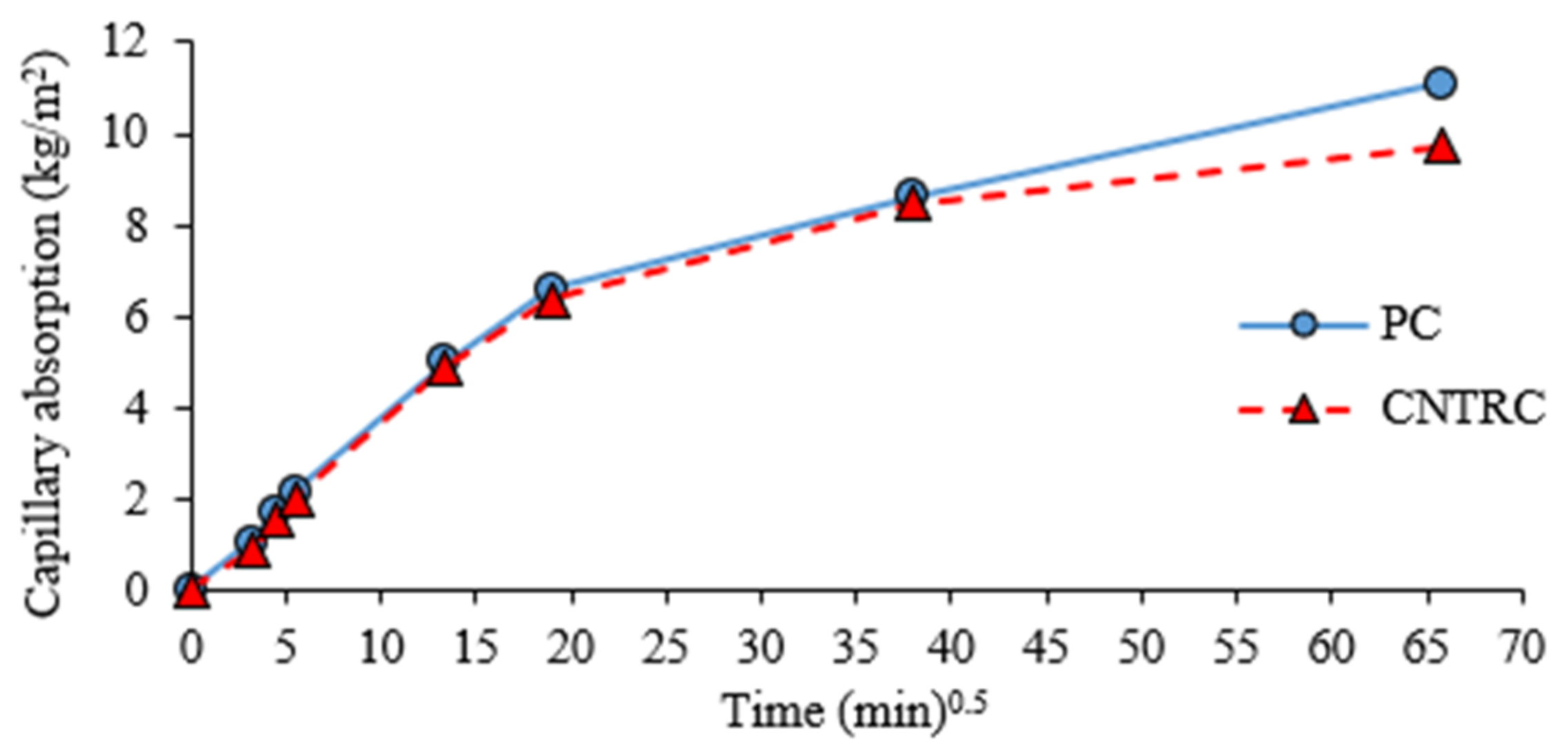
In general, both compositions showed absorption curves with similar shape (Figure 3). Contrary to what could be expected, the absorption did not vary linearly with the root of time. This is essentially related to the non-uniform moisture distribution in the concrete depth. In fact, absorption curves are characterized by a higher rate of absorption in the first three hours, followed by a significant decrease in the rate of absorption for later periods. Therefore, for uncracked specimens, each phase was analyzed separately. Two absorption coefficients were calculated, one for the initial period up to 3 h, Cabs,0–3h, and other up to 72 h, Cabs,6–72h. Both coefficients, as well as the water absorption at 72 h, are displayed in Table 5. A high R2 was obtained in each phase, suggesting a good correlation between the water absorption and the square root of time. There was a significant reduction from Cabs,0–3h to Cabs,6–72h. At later stages, the higher water content inside the specimens reduces the long-term water absorption and this phenomenon tends to be controlled by the progressive water uptake of less accessible and smaller pores near concrete surface [46].
As expected, the incorporation of CNT enabled the reduction of both coefficients of absorption, indicating the refinement of the concrete microstructure. However, contrary to what was found in a previous study [16], the highest reduction, of around 27%, was obtained for Cabs,6–72h. In fact, a greater contribution of CNT at early age would be expected, involving the water absorption of drier and more cracked surface concrete [30]. As mentioned earlier, this may be related to the higher contribution of the less accessible and smaller pores, where CNT may better participate through their nucleation and filler effects. On the other hand, the rapid water absorption during the first few minutes is affected by the variable surface characteristics of concrete specimens. Nevertheless, the overall reduction of the absorption coefficient was similar to that reported by Carriço et al. [24], of about 25%.
The absorption at 72 h registered a reduction of 12.3% in CNTRC, which was lower than that found for Cabs,6–72h. This means that CNT contributed to the refinement of the porous structure, but not that much to the reduction of total porosity. The same was also reported by [30].
In Table 5, the absorption coefficients of artificially cracked specimens are indicated, as well as the average crack depth (Lc) measured in each concrete composition. As expected, the cracked specimens showed higher absorption coefficients than reference uncracked concrete. This is a result of the higher initial absorption promoted by the crack itself. After this initial effect, the absorption rate gradually tends to approach that of reference concrete.
As for uncracked concrete, the CNT were also effective in reducing the absorption coefficient of cracked concrete (Table 5). The reduction of Cabs,0–3h and Cabs,6–72h was about 10 and 24%, respectively. In this case, besides the filler and nucleation effect, the bridging effect should have a more effective contribution. In uncracked conditions, the bridging effect may only act when the specimens are previously loaded or subjected to dimensional variations from temperature and humidity gradients. The CNT only participate in the crack opening reduction by arresting the microcrack propagation into macrocracking. As shown in Hawreen et al. [20], CNT are only able to bridge cracks up to about 1 µm. Therefore, in existing cracks with over 0.05 mm average crack width, the water absorption thought the crack should be the same in CNTRC and PC. Indeed, the incorporation of CNT should act in the reduction of the crack influence at three levels: reduction of microcracking around macrocracks, decreasing the level of absorption in its vicinity; reduction of the crack propagation into the concrete specimen; induction of narrower crack openings, for a given load, due to microcrack retention. Regarding this last point, as concrete specimens were produced and analyzed with the same target crack opening, the possible positive contribution of CNT in this action was not assessed.
Indeed, the direct comparison of the absorption coefficient in each concrete is not correct, because of the different crack depth between tested specimens. Therefore, to better understand the influence of the crack, the crack coefficient, βCR, was determined according to Equation (3) suggested by Bogas et al. [37], independent of the crack depth. This coefficient relates the absorption in cracked concrete, abscc, to the absorption in reference uncracked concrete, absuc, of the same composition. These parameters were arbitrarily determined at 6 h [37]. In this case, the abscc is normalized in order to be independent of the crack depth. To this end, the specimen surface area in contact with water, A0, is increased by the area of the crack walls, where D is the diameter and Lc is the crack length. The average βCR was 10% higher in PC than in CNTRC (Table 5), showing that the increase of absorption is more relevant in unreinforced concrete. This indicates the contribution of CNT to the microstructure refinement around the crack region.
In addition, the coefficient of absorption in the cracked region Cabs,CR was estimated according to Equation (4), which provides a direct measure of the crack influence in the capillary absorption [37]. In Equation (4) the absorption in the cracked region, absCR (additional absorption rate due to cracking) may be determined from Equation (5), where AC is the cracked area given by the product of the specimen diameter and the crack width.
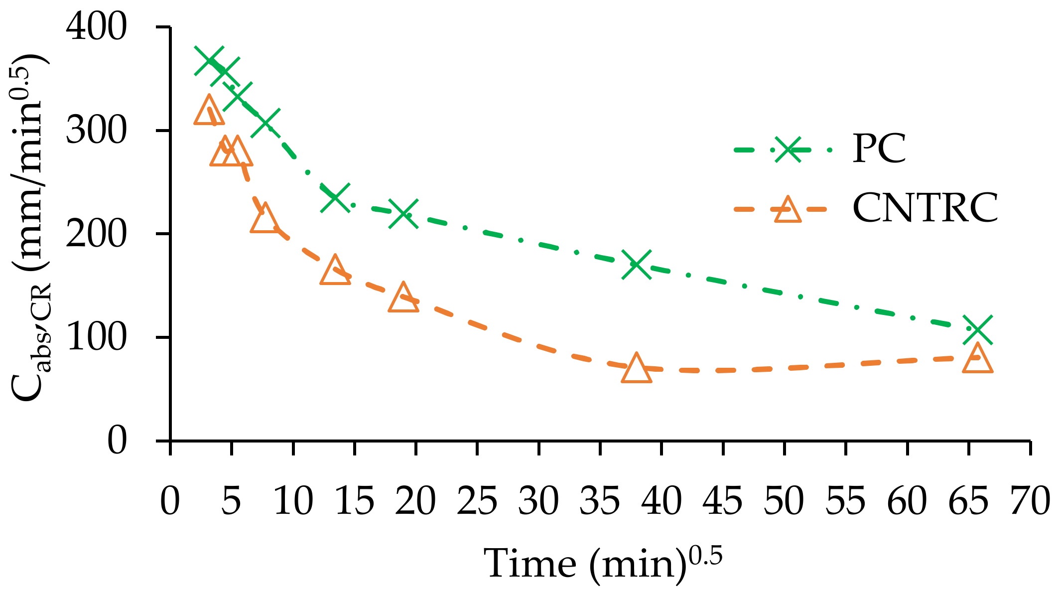
Figure 4 shows the evolution of Cabs,CR over time. It can be observed that the effect of the crack is decreasing with time. Compared to the absorption coefficients of uncracked reference concrete (Table 5), the cracked area presents significantly higher absorption rates than the uncracked area, which confirms that artificial cracks of 0.05 mm offer no significant resistance to water uptake. In addition, it is also confirmed that there is less influence of the crack in concrete reinforced with CNT. During the first 60 min, the Cabs,CR was over 40% lower in CNTRC than in PC.
Specimens with natural cracks are not comparable with any of the above, since the size and testing age were different, as well as the curing conditions. As mentioned in Section 2.4, these specimens were subjected to less drying and hence lower water absorption was expected. Moreover, due to the adopted cracking methodology (see Section 2.4), the crack went through all the specimen thickness. Therefore, only the early absorption was considered. The water abortion at 72 h, as well as the absorption coefficients up to 20 min, Cabs,0–20min, and between 6 and 72 h, Cabs,6–72h, are presented in Table 5. The consideration of absorption coefficients up to only 20 min is justified by the rapid absorption and the lower drying conditions of these specimens. The Cabs,6–72h occurred in almost full saturated concrete, without significant differences between concrete specimens. As mentioned, the average crack width in tested specimens were higher than the target values, because natural pre-cracking is more difficult to control. However, induced cracks from bending tests are usually V-shaped, being narrower in depth. Moreover, the average crack width only slightly varied between reference and CNT reinforced concrete (±20%, Table 5).
As expected, the absorption increased in concrete with wider cracks. However, the increase was low, because there was rapid water uptake through the crack and the exposed area to water absorption was not significantly altered. Therefore, the slight variation of crack width between concrete specimens (Table 5) had little influence in concrete results.
Assuming similar crack width in both concrete types the positive contribution of CNT in reducing the early absorption coefficient of cracked concrete is confirmed, regardless of the crack target width. On average, this reduction was 18% and 6% for crack widths of about 0.1 and 0.2 mm, respectively. The modest water absorption reduction in CNT reinforced concrete (12%, on average) may be partly related to the lower drying degree and less available empty small pores in natural cracked concrete, where CNT may better contribute to the reduction of water absorption.
3.3. Carbonation Resistance
The carbonation depth in the uncraked, xc, and cracked area, xCR, as well as the carbonation coefficient of the uncracked, Kc, and cracked area, Kc,CR, are presented in Table 6, involving the reference and the artificially or naturally cracked concrete specimens. The average crack characteristics (width and depth) are also presented in this table. In general, a good correlation (R2 > 0.9) with the square root of time was found, which confirms the suitability of Equation (1), based on Fick’s first law. The uncracked area in non-reference concrete corresponds to the specimen region sufficiently far from the crack influence (equivalent to the carbonation depth).
On average, the carbonation resistance was 18% improved with the CNT incorporation in uncracked concrete (Table 6). A slightly lower improvement, of 16%, was reported by Carriço et al. [24], taking into account the same type and amount of CNT reinforcement. Due to the preconditioning and dry exposure test conditions of the specimens, all mechanisms are likely involved in the reinforcement of the concrete matrix (filler, nucleation and bridging effect). Bridging can contribute to the reduction of the pore connectivity and consequently to CO2 diffusion in concrete by retaining crack propagation and reducing microcrack width. The nucleation effect should improve the carbonation resistance by densifying the microstructure of concrete and by increasing the amount of carbonated substances in the cementitious matrix.
The carbonation rate in the cracked region is influenced by the crack depth. Therefore, based on the methodology suggested in Bogas et al. [37], the carbonation coefficient through the crack, Kc,CR, was determined regardless of Lc. It was assumed that over Lc the carbonation depth in the cracked area, xCR, is increased at the same rate of the xc in the reference uncracked area. Then, from Equation (6), based on Equation (1), the time taken for the carbonation depth to reach Lc (tc) can be estimated. The xc,28d in Equation (6) is the carbonation depth after 28 days (t28) that is higher than Lc. At the end, Kc,CR is evaluated through Equation (7).
The carbonation resistance in the uncracked region of artificially cracked concrete was improved with the incorporation of CNT. However, this improvement (10%) was lower than that found in uncracked concrete (18%). Moreover, compared to uncracked specimens, the Kc in the uncracked region of cracked concrete was higher (Table 6), especially in CNT concrete, with no obvious justification for this trend, besides the possible different moisture conditions.
In addition, the Kc,CR was similar in concrete with and without CNT. This means that the contribution of CNT in cracks of about 0.05 mm width was not significant. In fact, the carbonation front propagation in this area essentially depends on the CO2 diffusion through the crack, not involving the region around. Therefore, for the same crack width, the behavior in different types of concrete tends to be identical.
In naturally cracked specimens, the carbonation depth was lower than the crack depth, which allowed the direct calculation of the carbonation coefficient in the cracked area, Kc,CR. The crack width and the carbonation depth at 7 and 28 days, for each tested concrete, as well as the respective carbonation coefficients, are presented in Table 6. The average crack width of CNT-reinforced concrete was 33% higher and 10% lower than that of reference concrete, for the targets 0.05 and 0.1 mm, respectively (Table 5).
As expected, the carbonation rate was significantly higher in the cracked area than in the uncracked region. Moreover, the Kc,CR increased in concrete with wider cracks. However, as for the capillary absorption, the carbonation rate was not greatly affected by the crack width. Therefore, the carbonation behavior should not be significantly affected by the crack width variation between concrete specimens.
The carbonation coefficient in the uncracked area was similar to that obtained in reference uncracked concrete. In addition, the Kc,CR was of the same order of that found in artificially cracked specimens, which suggests a little influence of the type of cracking in this mechanism. However, the Kc,CR was slightly reduced (9–10%) in concrete with CNT, regardless of the target crack width. As mentioned, the carbonation front under natural cracking occurred within the crack depth, which allowed the better contribution of the participation of CNT around the crack. In fact, the carbonation front was measured in the surrounding concrete around the crack instead of in the area over the crack tip, as occurred in artificially cracked concrete.
Nevertheless, these results suggest the participation of CNT in the retention of microcrack propagation in naturally cracked concrete. Contrary to artificial cracks, the natural cracks intercept the CNT reinforced matrix. Moreover, as the natural cracks are mechanically induced, they introduce greater disturbance in the region around the crack. On the other hand, the artificial cracks are molded without relevant disturbance in the crack vicinity. Therefore, it is expected that the CNT reinforcement can be more effective in the region of natural cracks than in artificial cracks of equivalent width.
As found for capillary absorption, the contribution of CNT tended to be higher for lower target crack widths, despite the lower average crack width of PC. It is possible that more small cracks around these cracks are benefited by the CNT bridging effect.
3.4. Chloride Ion Penetration
The chloride penetration coefficient, Dcl, and the crack width and depth are presented in Table 7. A modest decrease of the chloride ion penetration was reached with the addition of CNT (7%) (Figure 5a). The same level of reduction is reported in [24] for the same type and content of CNT. This is attributed to the fact that specimens were wet cured until testing, without pre-loading or drying shrinkage, preventing the development of microcracking. Moreover, contrary to the previous tests, since the chloride migration test involves all the specimen thickness, the contribution of CNT upon surface microcracking becomes less relevant. Therefore, the contribution of CNT is essentially limited to the nucleation and filler effects. In fact, the percentage improvement attained in these tests was close to that found in the long-term 72 h capillary absorption (Section 3.2).
The coefficients of diffusion in the uncracked (Dcl) and cracked region (Dcl,CR) of artificially cracked concrete are presented in Table 7 and Figure 5a. The values of Dcl in uncracked region were similar to those in uncracked concrete, showing that specimens were produced and tested in identical conditions.
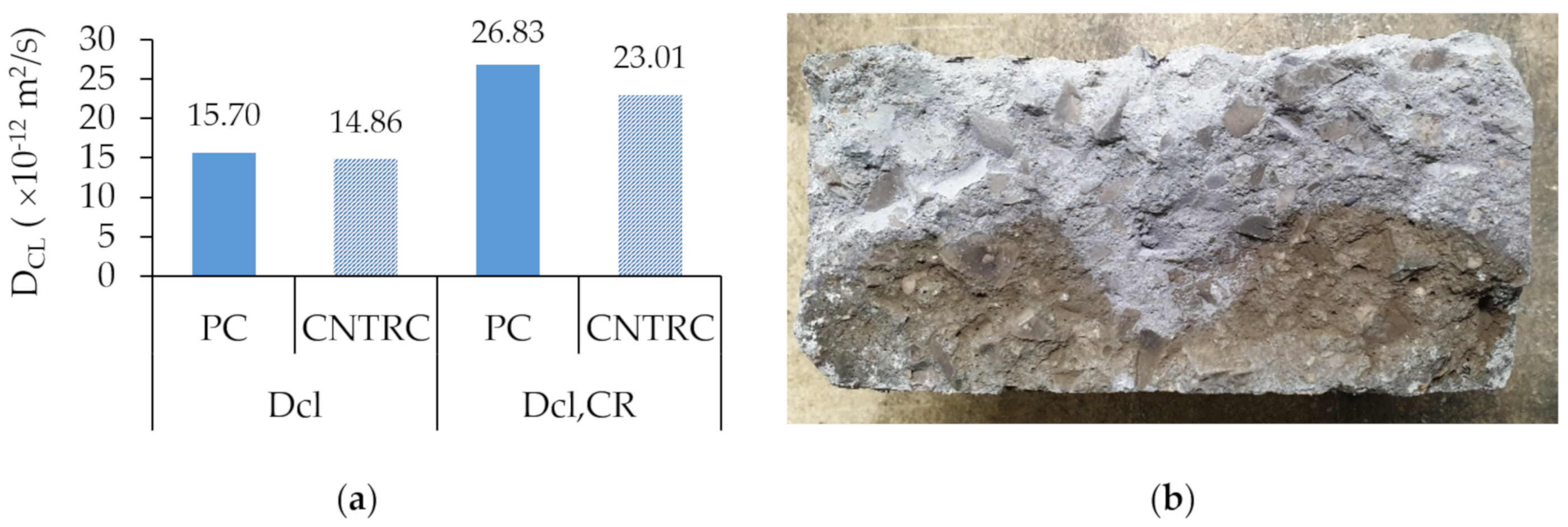
The incorporation of CNT led to only a 5% reduction of Dcl in the uncracked region (similar to what was found in uncracked specimens), but to as much as 14% in the cracked region. Moreover, the crack depth was slightly higher in CNT concrete (7%, Table 7). Therefore, despite the low microcracking induced around artificial cracks (Section 3.3), the positive contribution of CNT in reducing the DCl,CR is confirmed.
As expected, the chloride coefficient of the cracked region was significantly higher than that of the uncracked area. However, this increase was lower in concrete with CNT (58%) than in plain concrete (71%). This also suggests a lower influence of cracking in the chloride penetration resistance of concrete with CNT. Note that it is not only the crack alignment that is affected by the chloride penetration, but also the surrounding area, as shown in Figure 5b.
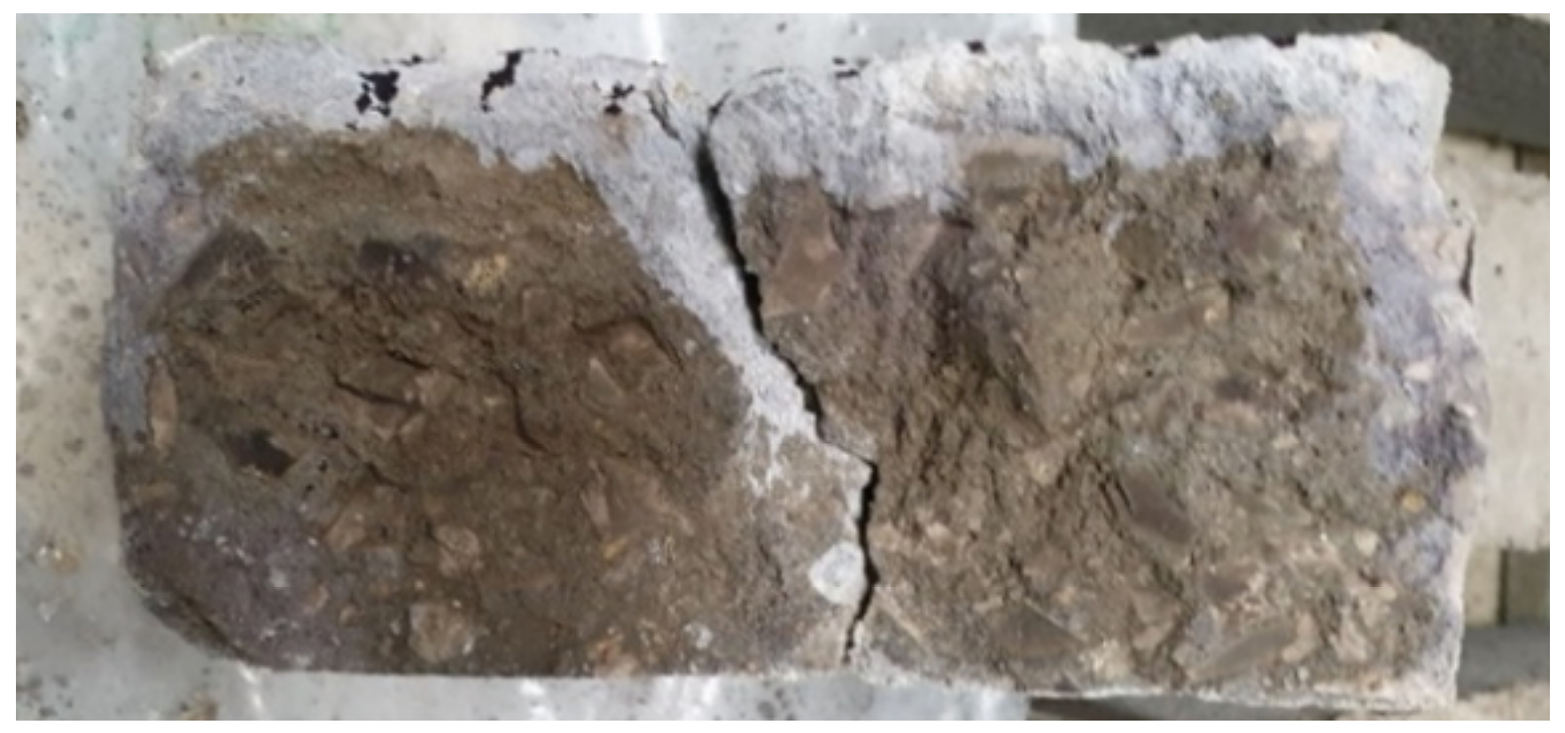
In naturally cracked concrete, the Dcl,CR is independent of the crack length, because it involves all the specimen thickness. This allows a more accurate comparison between different concretes. There was a substantial increase of Dcl in natural cracked specimens, even in the uncracked region. This is mainly explained by the different testing conditions, in which the crack crossing the specimen’s thickness sped up the chloride penetration (Figure 6). This phenomenon is more relevant in wider cracks.
The incorporation of CNT led to a relevant reduction of the Dcl in the uncracked area of about 35%, regardless of the target crack width. Two main reasons may be attributed to this improvement: the fact that the uncracked region is also affected by the crack and its surrounding area; the greater contribution of the CNT near the natural cracks, which, as mentioned, is more disturbed than the vicinity of artificial cracks.
However, the Dcl,CR was less affected by the incorporation of CNT. The reduction of this property was only 8–10% for the different crack widths, compared to plain concrete. As mentioned, the CNT are not able to participate within the crack alignment due to their large width. The contribution may essentially occur in the microcracked area of the crack vicinity. This is better shown in Section 3.5.
3.5. Microscopic Analysis
SEM analysis were carried out in some samples collected from the region indicated in Figure 7 and Figure 8, perpendicular to the natural and artificial cracks, respectively. The objective was to confirm the possible participation of CNT in improving the concrete microstructure in the vicinity of the induced macrocrack.
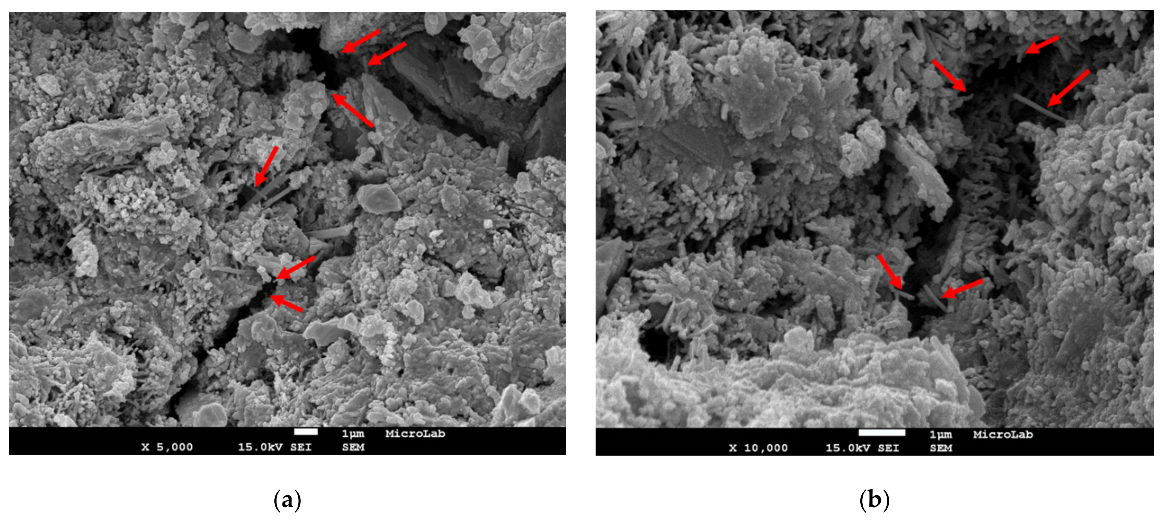
In general, the CNT were well dispersed, and no significant agglomerations were detected. However, the CNT were not well-spaced between them, with some regions where they were absent. As expected, the naturally cracked specimen was more microcracked than the artificially cracked one, confirming the greater perturbation of the region near the mechanically induced natural cracks (Figure 7). Although only one section was analyzed per each type of cracking, it was possible to observe some cases where CNT were effective in bridging and being involved by hydration products (Figure 7a–c and Figure 8d). In addition, in some narrower microcracks, possibly diverging from the main crack, CNT were broken, pulled-out, or stretched between crack walls (Figure 7a and Figure 8b).
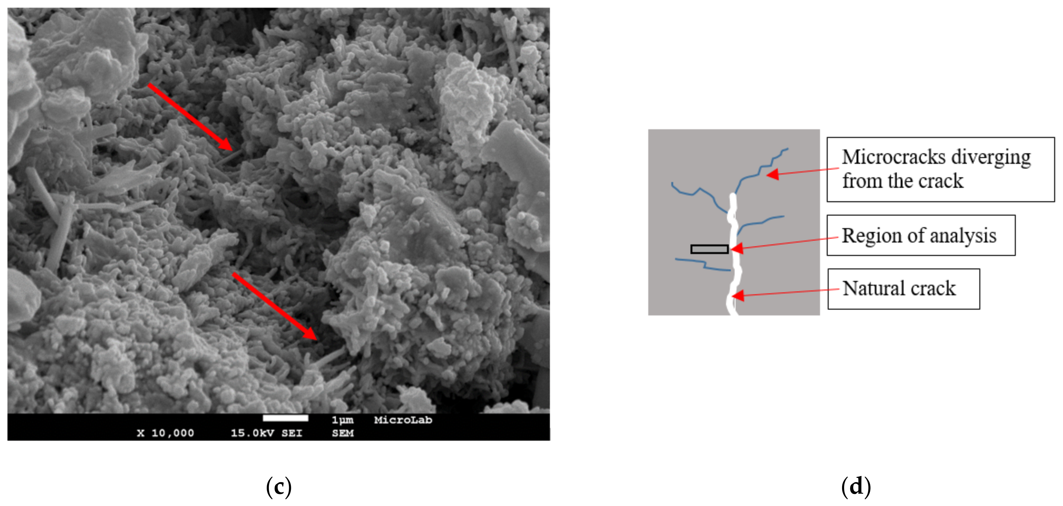
Fewer cases of CNT bridging around artificial cracks were found, because the specimen was less microcracked. However, in more porous regions it was also visible that the CNT were effectively linking the hydration products and increasing the cohesion between them (Figure 8). Nevertheless, only from SEM analysis is it not possible to conclude that CNT were more effective near the natural cracks.
4. Conclusions
In this study, the durability of cracked concrete reinforced with CNT was analyzed by means of capillary absorption, carbonation, and chloride penetration tests.
The incorporation of CNT was shown to be efficient in improving the mechanical and analyzed durability properties of uncracked concrete, with little influence on the concrete density and workability. Compared to reinforced reference concrete, the mechanical strength and chloride penetration resistance were only moderately improved (up to 10%), while the properties measured in concrete previously subjected to drying conditions (promoting microcrack formation), namely capillary absorption and carbonation resistance, were improved up to 18% and 27%, respectively. In cracked concrete, CNT may further participate in arresting the microcrack propagation near the macrocracks.
As expected, it was found that the capillary absorption, carbonation, and chloride penetration may be significantly increased in cracked concrete. Moreover, the water absorption, carbonation, and chloride diffusion only slightly varied with the crack width, for the range considered in this study. Cracks over 0.05 mm offered lower resistance to water and gas percolation, regardless of the incorporation of CNT. For the crack width range considered in this study, the main contribution of CNT occurred in the crack vicinity.
The CNT contributed in reducing the influence of cracking in the capillary absorption. This was confirmed by the 9% and over 40% reduction achieved in the new suggested crack coefficient, βCR, and in the estimated absorption coefficient of the cracked region, respectively. Moreover, an average 12% reduction of the rate of absorption was found in naturally cracked CNT-reinforced concrete.
The carbonation coefficient through the artificial crack, Kc,CR, was not significantly altered with the incorporation of CNT. The measured carbonation depth was essentially controlled by the diffusion of CO2 trough the crack, without involving the CNT-reinforced concrete in its vicinity. However, in naturally cracked concrete, the Kc,CR was up to 10% lower in concrete with CNT than in plain concrete. In this case, the carbonation front occurred within the crack depth, allowing to show the more evident participation of CNT in the concrete region around the crack.
The chloride penetration resistance was improved in both artificially and naturally cracked concrete with the CNT addition. The diffusion coefficient in the artificial crack region was 14% reduced, which led to a lower influence of cracking in the chloride penetration resistance. However, in naturally cracked concrete the CNT was shown to greatly contribute in the crack surrounding area, reducing the Dcl in about one third.
Author Contributions
Conceptualization, J.A.B., H.H.A.; methodology, J.A.B., H.H.A.; formal analysis, J.A.B., H.H.A.; investigation, J.A.B., H.H.A. and T.D.; resources, J.A.B.; data curation, J.A.B., H.H.A.; writing—original draft preparation, J.A.B., H.H.A.; writing—review and editing, J.A.B., H.H.A.; funding acquisition, J.A.B. All authors have read and agreed to the published version of the manuscript.
Funding
This research received no external funding.
Institutional Review Board Statement
Not applicable.
Informed Consent Statement
Not applicable.
Data Availability Statement
Not applicable.
Acknowledgments
The authors wish to thank Foundation for Science and Technology (FCT) for funding this research under project UIDB/ECI/04625/2020 (CERIS), as well as the companies SECIL and BASF for supplying the materials used in the experiments. The author also acknowledge the collaboration of Ana Mafalda Guedes on the experimental work.
Conflicts of Interest
The authors declare no conflict of interest.
References
- Zhang, J.; Stang, H. Application of stress crack width relationship in predicting the flexural behaviour of fiber reinforced concrete. Cem. Concr. Res. 1998, 28, 439–452. [Google Scholar] [CrossRef]
- Komlos, K.; Babal, B.; Nurnbergerova, T. Hybrid fiber- reinforced concrete under repeated loading. Nucl. Eng. Des. 1995, 156, 195–200. [Google Scholar] [CrossRef]
- Eguchi, K.; Teranishi, K. Prediction equation of drying shrinkage of concrete based on composite model. Cem. Concr. Res. 2005, 35, 483–493. [Google Scholar] [CrossRef]
- Camacho, M.; Galao, O.; Baeza, F.; Zornoza, E.; Garcés, P. Mechanical Properties and Durability of CNT Cement Composites. Materials 2014, 7, 1640–1651. [Google Scholar] [CrossRef]
- De Schutter, G. Quantification of the influence of cracks in concrete structures on carbonation and chloride penetration. Mag. Concr. Res. 1999, 51, 427–435. [Google Scholar] [CrossRef]
- Wang, K.; Jansen, D.C.; Shah, S.P.; Karr, A.F. Permeability study of cracked concrete. Cem. Concr. Res. 1997, 27, 381–393. [Google Scholar] [CrossRef] [Green Version]
- Sullivan-Green, L. Effect of Crack Width on Carbonation: Implications for Crack-Dating; Northwestern University: Evanston, IL, USA, 2005. [Google Scholar]
- Aldea, C.M.; Shah, S.P.; Karr, A. Permeability of cracked concrete. Mater. Struct. 1999, 32, 370–376. [Google Scholar] [CrossRef]
- Ismail, M.; Toumi, A.; François, R.; Gagné, R. Effect of crack opening on the local diffusion of chloride in inert materials. Cem. Concr. Res. 2004, 34, 711–716. [Google Scholar] [CrossRef]
- Jang, S.Y.; Kim, B.S.; Oh, B.H. Effect of crack width on chloride diffusion coefficients of concrete by steady-state migration tests. Cem. Concr. Res. 2011, 41, 9–19. [Google Scholar] [CrossRef]
- Shin, K.J.; Bae, W.; Choi, S.W.; Son, M.W.; Lee, K.M. Parameters influencing water permeability coefficient of cracked concrete specimens. Constr. Build. Mater. 2017, 151, 907–915. [Google Scholar] [CrossRef]
- Alahmad, S.; Toumi, A.; Verdier, J.; François, R. Effect of crack opening on carbon dioxide penetration in cracked mortar samples. Mater. Struct. Constr. 2009, 42, 559–566. [Google Scholar] [CrossRef]
- Djerbi, A.; Bonnet, S.; Khelidj, A.; Baroghel-bouny, V. Influence of traversing crack on chloride diffusion into concrete. Cem. Concr. Res. 2008, 38, 877–883. [Google Scholar] [CrossRef] [Green Version]
- Hameed, R.; Turatsinze, A.; Duprat, F.; Sellier, A. Metallic fiber reinforced concrete: Effect of fiber aspect ratio on the flexural properties. Arpn. J. Eng. Appl. Sci. 2009, 4, 67–72. [Google Scholar]
- Majumdar, A.; Ryder, J. Glassfiber Reinforcement for Cement Products. Glass Technol. 1968, 9, 78–84. [Google Scholar]
- Bogas, A.H.J. Capillary Absorption and Oxygen Permeability of Concrete Reinforced with Carbon Nanotubes. Adv. Civ. Eng. Mater. 2019, 8, 307–326. [Google Scholar] [CrossRef]
- Hawreen, A.; Bogas, J.A.; Kurda, R. Mechanical Characterization of Concrete Reinforced with Different Types of Carbon Nanotubes. Arab J. Sci. Eng. 2019, 44, 8361–8376. [Google Scholar] [CrossRef]
- Hawreen, A.; Bogas, J.A. Shrinkage and mechanical properties of concrete reinforced with different types of carbon nanotubes. Constr. Build. Mater. 2019, 198, 70–81. [Google Scholar] [CrossRef]
- Bogas, A.; Hawreen, A.; Olhero, S.; Ferro, A.C.; Guedes, M. Selection of dispersants for stabilization of unfunctionalized carbon nanotubes in high pH aqueous suspensions: Application to cementitious matrices. Appl. Surf. Sci. 2019, 463, 169–181. [Google Scholar] [CrossRef]
- Ahmed, H.; Bogas, J.A.; Guedes, M.; Costa Pereira, M.F. Dispersion and reinforcement efficiency of carbon nanotubes in cementitious composites. Mag. Concr. Res. 2019, 71, 408–423. [Google Scholar] [CrossRef]
- Hawreen, A.; Bogas, J.A. Influence of carbon nanotubes on steel–concrete bond strength. Mater. Struct. 2018, 51, 155. [Google Scholar] [CrossRef]
- Hawreen, A.; Bogas, J.A.; Guedes, M. Mechanical Behavior and Transport Properties of Cementitious Composites Reinforced with Carbon Nanotubes. J. Mater. Civ. Eng. 2018, 30, 04018257. [Google Scholar]
- Hawreen, A.; Bogas, J.A.; Dias, A.P.S. On the mechanical and shrinkage behavior of cement mortars reinforced with carbon nanotubes. Constr. Build. Mater. 2018, 168, 459–470. [Google Scholar] [CrossRef]
- Carriço, A.; Bogas, J.A.; Hawreen, A.; Guedes, M. Durability of multi-walled carbon nanotube reinforced concrete. Constr. Build. Mater. 2018, 164, 121–133. [Google Scholar] [CrossRef]
- Gao, L.; Jiang, L.; Sun, J. Carbon nanotube-ceramic composites. J. Electroceram. 2006, 17, 51–55. [Google Scholar] [CrossRef]
- Samal, S.S.; Bal, S. Carbon Nanotube Reinforced Ceramic Matrix Composites—A Review. J. Min. Mater. Charact. Eng. 2008, 7, 355. [Google Scholar] [CrossRef]
- Yu, M.; Lourie, O.; Dyer, M.J.; Moloini, K.; Kelly, T.F. Strength and Breaking Mechanism of Multiwalled Carbon Nanotubes Under Tensile Load. Science 2000, 287, 637–640. [Google Scholar] [CrossRef] [Green Version]
- Mindess, S.; Young, J. Darwin Concrete, 2nd ed.; Prentice Hall: Upper Saddle River, NJ, USA, 2018. [Google Scholar]
- Monteiro, M.P. Concrete: Microstructure, Properties and Materials; McGraw-Hill Professional Publishing: New York, NY, USA, 2013. [Google Scholar]
- Nochaiya, T.A. Chaipanich Behavior of multi-walled carbon nanotubes on the porosity and microstructure of cement-based materials. Appl. Surf. Sci. 2011, 257, 1941–1945. [Google Scholar] [CrossRef]
- EN 197-1:2012. Cement—Part 1: Composition, Specifications and Conformity Criteria for Common Cements; European Committee for Standardization (CEN): Brussels, Belgium, 2012. [Google Scholar]
- EN 12350-2: 2009. Testing Fresh Concrete. Slump Test; European Committee for Standardization (CEN): Brussels, Belgium, 2009. [Google Scholar]
- EN 12350-6: 2009. Testing Fresh Concrete. Density; European Committee for Standardization (CEN): Brussels, Belgium, 2009. [Google Scholar]
- EN 12390-3: 2009. Testing Hardened Concrete. Compressive Strength of Test Specimens; European Committee for Standardization (CEN): Brussels, Belgium, 2009. [Google Scholar]
- Rilem. TC116-PCD Permeability of concrete as a criterion of its durability. Recomendations. Tests for gas permeability of concrete 1999, determination of the capillary absorption of water of hardened concrete. Mater. Struct. 1999, 32, 174–179. [Google Scholar]
- LNEC E391. Concrete. Carbonation resistance. LNEC Specification; Laboratório Nacional de Engenharia Civil (LNEC): Lisbon, Portugal, 1993. [Google Scholar]
- Bogas, J.A.; Carriço, A.; Pontes, J. Influence of cracking on the capillary absorption and carbonation of structural lightweight aggregate concrete. Cem. Concr. Compos. 2019, 104, 103382. [Google Scholar] [CrossRef]
- LNEC E393. Concrete. Capillary Absorption; Laboratório Nacional de Engenharia Civil (LNEC): Lisbon, Portugal, 1993. [Google Scholar]
- LNEC E463. Concrete—Determination of the Chloride Diffusion Coefficient by Non-Stationary Migration Test; Laboratório Nacional de Engenharia Civil (LNEC): Lisbon, Portugal, 2004. [Google Scholar]
- NTBUILD 492. Concrete Mortar and Cement-Based Repair Materials: Chloride Migration Coefficient from Non-Steady-State Migration Experiences; Nordtest Method: Espoo, Finland, 1999. [Google Scholar]
- Makar, J.; Margeson, J.; Luh, J. Carbon Nanotube/Cement Composites—Early Results and Potential Application. In Proceedings of the 3rd International Conference on Construction Materials: Performance, Innovations and Structural Implications, Vancouver, BC, Canada, 22–24 August 2005; pp. 1–10. [Google Scholar]
- Al-Rub, R.; Tyson, M.B.; Yazdanbakhsh, A.Z. Grasley Mechanical properties of nanocomposite cement incorporating surface-treated and untreated carbon nanotubes and carbon nanofibers. J. Nanomech. Micromech. 2012, 1, 3–8. [Google Scholar]
- Collins, F.; Lambert, J.; Duan, W.H. The influences of admixtures on the dispersion, workability, and strength of carbon nanotube—OPC paste mixtures. Cem. Concr. Compos. 2012, 34, 201–207. [Google Scholar] [CrossRef]
- Zou, B.; Chen, S.; Korayem, A.; Collins, F.; Wang, C.; Duan, W. Effect of ultrasonication energy on engineering properties of carbon nanotube reinforced cement pastes. Carbon 2015, 85, 21–220. [Google Scholar] [CrossRef]
- Li, Y.; Wang, M.; Zhao, X. Mechanical behavior and microstructure of cement composites incorporating surface-treated multi-walled carbon nanotubes. Carbon 2005, 43, 1239–1245. [Google Scholar] [CrossRef]
- Martys, N.; Ferraris, C. Capillary transport in mortars and concrete. Cem. Concr. Res. 1997, 27, 747–760. [Google Scholar] [CrossRef]
Figure 1.
Introducing (a) artificial cracks using a plastic sheet and (b) natural cracks from bending tests. (c) Drilled core specimens after natural cracking.
Figure 1.
Introducing (a) artificial cracks using a plastic sheet and (b) natural cracks from bending tests. (c) Drilled core specimens after natural cracking.

Figure 2.
(a) Capillary absorption test. (b) Measure of carbonation depth in different sections, perpendicular to the crack.
Figure 2.
(a) Capillary absorption test. (b) Measure of carbonation depth in different sections, perpendicular to the crack.

Figure 3.
Capillary absorption over time for uncracked concrete specimens.

Figure 4.
Absorption coefficient in the cracked area, Cabs,CR, over time.

Figure 5.
(a) Chloride coefficients in artificially cracked concrete. (b) Artificially cracked specimens after chloride attack.
Figure 5.
(a) Chloride coefficients in artificially cracked concrete. (b) Artificially cracked specimens after chloride attack.

Figure 6.
Naturally cracked specimens subjected to chloride attack, after splitting and pulverizing with silver nitrate.
Figure 6.
Naturally cracked specimens subjected to chloride attack, after splitting and pulverizing with silver nitrate.

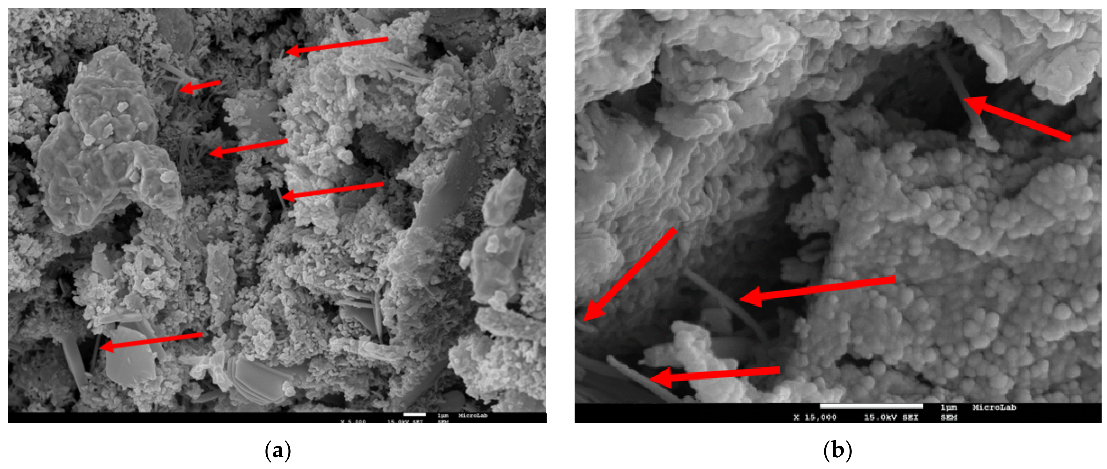
Figure 7.
(a–c) SEM analysis of CNTRC with natural cracking (arrows indicate CNT tips or bridging). (d) scheme of concrete region analyzed in SEM analysis.
Figure 7.
(a–c) SEM analysis of CNTRC with natural cracking (arrows indicate CNT tips or bridging). (d) scheme of concrete region analyzed in SEM analysis.


Figure 8.
(a–c) SEM analysis of CNTRC with artificial cracking (arrows indicate CNT tips or bridging). (d) scheme of concrete region analyzed in SEM analysis.
Figure 8.
(a–c) SEM analysis of CNTRC with artificial cracking (arrows indicate CNT tips or bridging). (d) scheme of concrete region analyzed in SEM analysis.


Table 1.
Characteristics of carbon nanotubes (CNT) provided by the supplier.
| Purity | Outer Diameter | Inner Diameter | Length | Specific Surface Area | Density |
|---|---|---|---|---|---|
| >98% | 20–80 nm | 5–15 nm | 10–20 μm | >60 m2/g | ~2.1 g/cm3 |
Table 2.
Physical characteristics of aggregates.
| Properties | Fine Aggregates | Coarse Aggregates | ||
|---|---|---|---|---|
| Fine Sand | Coarse Sand | Fine Gravel | Coarse Gravel | |
| Water absorption at 24 h (%) | 0.16 | 0.38 | 0.63 | 0.37 |
| Density of the dried particles (kg/m3) | 2577 | 2595 | 2591 | 2504 |
| Density of impermeable particles (kg/m3) | 2588 | 2621 | 2634 | 2528 |
| Density of saturated surface dried particles (kg/m3) | 2581 | 2605 | 2608 | 2513 |
| Bulk density (kg/m3) | 1573 | 1512 | 1313 | 1355 |
| Granulometric fraction (d15/D90) | 0.125/1 | 0.5/4 | 2/6.3 | 5.6/11.2 |
Table 3.
Concrete compositions.
| Mix | w/c | Cement (kg/m3) | Water (kg/m3) | Fine Sand (kg/m3) | Coarse Sand (kg/m3) | Fine Gravel (kg/m3) | Coarse Gravel (kg/m3) | CNT (g/m3) |
|---|---|---|---|---|---|---|---|---|
| PC | 0.55 | 380 | 214 | 303 | 454 | 242 | 710 | |
| CNTRC | 0.55 | 380 | 210 | 303 | 454 | 242 | 710 | 4222 |
Table 4.
Fresh density (ρf), 28 days hardened density (ρ28d), and 28 days compressive strength (fcm,28d) of concrete.
Table 4.
Fresh density (ρf), 28 days hardened density (ρ28d), and 28 days compressive strength (fcm,28d) of concrete.
| Fresh Density | Slump | Hardened Density | Compressive Strength | ||||
|---|---|---|---|---|---|---|---|
| Mix | ρf (kg/m3) | Δ (%) | (cm) | ρ28d (kg/m3) | Δ (%) | fcm,28d (MPa) | Δ (%) |
| PC | 2290 | - | 17.5 | 2354 | - | 45.6 | - |
| CNTRC | 2303 | 0.6 | 18.0 | 2364 | 0.4 | 50.0 | 9.8 |
Table 5.
Capillary absorption coefficients and 72 h water abortion for concrete under different cracking conditions.
Table 5.
Capillary absorption coefficients and 72 h water abortion for concrete under different cracking conditions.
| Cracking Condition | Mix | Crack Width 1 | Crack Depth, Lc | Capillary Absorption | Water Absorption | |||
|---|---|---|---|---|---|---|---|---|
| Cabs,0–20min | Cabs,0–3h | Cabs,6–72h | βCR | at 72 h | ||||
| (mm) | (mm) | (mm/min0.5) | (kg/m2) | |||||
| uncracked | PC | - | - | 0.371 | 0.095 | 11.08 | ||
| CNTRC | - | - | 0.363 | 0.069 | 9.71 | |||
| artificially cracked | PC | 0.05 | 18 | 0.515 | 0.132 | 0.954 | ||
| CNTRC | 0.05 | 18 | 0.466 | 0.107 | 0.868 | |||
| naturally cracked | PC | 0.05 (0.1) | - | 0.264 | 0.017 | 2.42 | ||
| 0.1 (0.16) | - | 0.266 | 0.019 | 2.64 | ||||
| CNTRC | 0.05 (0.08) | - | 0.217 | 0.018 | 2.28 | |||
| 0.1 (0.2) | - | 0.251 | 0.016 | 2.34 | ||||
1 target crack width (measured average crack width).
Table 6.
Carbonation resistance for concrete under different cracking conditions.
| Cracking Condition | Mix | Crack Width 1 | Crack Depth, Lc | Region of Testing | Carbonation Depth | Carbonation Coefficient | ||||
|---|---|---|---|---|---|---|---|---|---|---|
| xc (mm) | Kc | R2 | ||||||||
| (mm) | (mm) | 7 Days | 28 Days | 56 Days | 90 Days | (mm/Year0.5) | ||||
| uncracked | PC | - | - | 7 | 10.2 | 12.7 | 25.7 | 0.99 | ||
| CNTRC | - | - | 5.6 | 9.1 | 9.9 | 21.1 | 0.98 | |||
| artificially cracked | PC | 0.05 | 18 | uncracked | 10.2 | 12.4 | 14.5 | 31.2 | 0.97 | |
| cracked | 17.2 | 19.3 | 23.2 | 67.1 | ||||||
| CNTRC | 0.05 | 18 | uncracked | 9.9 | 11.5 | 12.4 | 28.2 | 0.93 | ||
| cracked | 16.9 | 18.4 | 19.9 | 65.8 | ||||||
| naturally cracked | PC | 0.05 (0.06) | - | uncracked | 2.9 | 7.3 | 25.1 | 0.98 | ||
| cracked | 10.2 | 19.9 | 72.3 | 0.99 | ||||||
| 0.10 (0.19) | - | uncracked | 3.8 | 7.1 | 25.9 | 0.99 | ||||
| cracked | 13 | 21.4 | 80.7 | 0.98 | ||||||
| CNTRC | 0.05 (0.09) | - | uncracked | 2.5 | 6.9 | 23.6 | 0.97 | |||
| cracked | 9.1 | 18.2 | 65.6 | 1 | ||||||
| 0.10 (0.17) | - | uncracked | 3.5 | 7.1 | 25.5 | 0.99 | ||||
| cracked | 10.2 | 20.5 | 73.9 | 1 | ||||||
1 target crack width (measured average crack width).
Table 7.
Chloride penetration resistance for concrete under different cracking conditions.
| Cracking Condition | Mix | Crack Width 1 (mm) | Crack Depth, Lc (mm) | Chloride Diffusion Coefficient | |
|---|---|---|---|---|---|
| Dcl (×10−12 m2/s) | Dcl,CR (×10−12 m2/s) | ||||
| Uncracked | PC | - | - | 15.81 | - |
| CNTRC | - | - | 14.74 | - | |
| Artificially cracked | PC | 0.05 | 20.1 | 15.7 | 26.83 |
| CNTRC | 0.05 | 18.8 | 14.86 | 23.01 | |
| Naturally cracked | PC | 0.05 (0.11) | 49.3 | 58.53 | 123.15 |
| CNTRC | 0.05 (0.07) | 48.5 | 37.17 | 113.01 | |
| PC | 0.1 (0.16) | 49.4 | 66.44 | 129.31 | |
| CNTRC | 0.1 (0.18) | 48.6 | 43.07 | 115.19 | |
1 target crack width (measured average crack width).
Publisher’s Note: MDPI stays neutral with regard to jurisdictional claims in published maps and institutional affiliations. |
© 2021 by the authors. Licensee MDPI, Basel, Switzerland. This article is an open access article distributed under the terms and conditions of the Creative Commons Attribution (CC BY) license (http://creativecommons.org/licenses/by/4.0/).
Share and Cite
MDPI and ACS Style
Bogas, J.A.; Ahmed, H.H.; Diniz, T. Influence of Cracking on the Durability of Reinforced Concrete with Carbon Nanotubes. Appl. Sci. 2021, 11, 1672. https://0-doi-org.brum.beds.ac.uk/10.3390/app11041672
AMA Style
Bogas JA, Ahmed HH, Diniz T. Influence of Cracking on the Durability of Reinforced Concrete with Carbon Nanotubes. Applied Sciences. 2021; 11(4):1672. https://0-doi-org.brum.beds.ac.uk/10.3390/app11041672
Chicago/Turabian StyleBogas, Jose Alexandre, Hawreen Hasan Ahmed, and Tomás Diniz. 2021. "Influence of Cracking on the Durability of Reinforced Concrete with Carbon Nanotubes" Applied Sciences 11, no. 4: 1672. https://0-doi-org.brum.beds.ac.uk/10.3390/app11041672
Note that from the first issue of 2016, this journal uses article numbers instead of page numbers. See further details here.