Article

Theoretical Analysis and Design of an Innovative Coil Structure for Transcranial Magnetic Stimulation

1
State Key Laboratory of Electrical Insulation and Power Equipment, School of Electrical Engineering, Xi’an Jiaotong University, Xi’an 710049, China
2
Department of Oncology, Johns Hopkins University School of Medicine, Baltimore, MD 21225, USA
3
School of Electronic Information and Artificial Intelligence, Shaanxi University of Science and Technology, Xi’an 710021, China
*
Authors to whom correspondence should be addressed.
Submission received: 25 January 2021 / Revised: 14 February 2021 / Accepted: 19 February 2021 / Published: 23 February 2021
(This article belongs to the Section Electrical, Electronics and Communications Engineering)

Abstract

:

Featured Application

Since magnetic stimulation can activate brain tissue with optimum intensity and frequency, it demonstrates great potential for many medical applications, procedures, and treatments. For example, it makes it easier to reach a deeper region beneath the skin without causing any trauma or pain. In addition, magnetic stimulation does not leave any residues in the operated tissues. However, the magnetic fields generated by typical and conventional coils are uniform around their targets, and their magnetic stimulation performance still needs improvement. Thus, an innovative coil that has a quad coil form was proposed for transcranial magnetic stimulation, which makes it possible to shrink the irritative zone and strengthen the stimulation intensity, thus achieving higher magnetic stimulation performance.

Abstract

Previous research showed that pulsed functional magnetic stimulation can activate brain tissue with optimum intensity and frequency. Conventional stimulation coils are always set as a figure-8 type or Helmholtz. However, the magnetic fields generated by these coils are uniform around the target, and their magnetic stimulation performance still needs improvement. In this paper, a novel type of stimulation coil is proposed to shrink the irritative zone and strengthen the stimulation intensity. Furthermore, the electromagnetic field distribution is calculated and measured. Based on numerical simulations, the proposed coil is compared to traditional coil types. Moreover, the influential factors, such as the diameter and the intersection angle, are also analyzed. It was demonstrated that the proposed coil has a better performance in comparison with the figure-8 coil. Thus, this work suggests a new way to design stimulation coils for transcranial magnetic stimulation.

1. Introduction

Nowadays, the bio-effects of magnetic fields are recognized. Magnetic stimulation has many advantages. For instance, it makes it easier to reach a deeper region beneath the skin without causing any trauma or pain. In addition, magnetic stimulation does not leave any residues in the operated tissues. Thus, due to its unique advantages, magnetic field stimulation has drawn considerable interest around the world [1,2]. Based on magnetic stimulations, transcranial magnetic stimulation (TMS) devices have been widely used in clinics and for medical research. In particular, with magnetic fields, current can be induced in target cells, leading to changes in the action potential. Furthermore, using repeated stimulations, ailments, such as epilepsy and depression, can be alleviated [3,4]. However, despite such advances, the intensity and the stimulated areas are still limited by the signal generator system and the stimulation coil design.
Traditional magnetic stimulation systems consist of microprocessors, signal generators, and stimulation coils. The strength and focality are the most critical performance indicators of the magnetic stimulation of brain tissue, as the strength of the stimulus should fit the location of the target area, and the stimulus should not affect the neighboring regions around the target nerves. Many studies were carried out to improve the performance of stimulation systems. In 2010, Yang proposed a circular coil array for TMS, that circular coil arrays have significantly larger stimulation intensity in comparison with conventional circular coils [5]. Li studied the double-butterfly coil for transcranial magnetic stimulation, and the coil’s focality proved to be better than that of typical coils [6]. Furthermore, Liu proposed a pulsed magnetic field generator that provided a noncontact way for functional nerve stimulations, where the magnetic field and induced electric field were produced by a figure-8 coil under the excitation of a pulsed discharging current [7]. Based on our previous work, a solenoid was proposed to stimulate the injured sciatic nerves of rats, and the regeneration process of the injured sciatic nerves was facilitated with pulsed magnetic stimulation [8]. Peterchev compared 50 coil designs and studied the trade-off between the strength and the focality [9]. Despite the great progress of the use of magnetic fields in nerve stimulation, the study on stimulation coil is mainly a study of qualitative theory analysis and lacks in a systems optimization method that is exercisable. To improve the performance of magnetic stimulation, it is necessary to pay attention to both field strength and the focality.
Herein, to meet the goal of the higher performance of stimulations, the requirements of the TMS coil were analyzed. Based on this research, a novel type of quad structure coil was designed. Moreover, a three-dimensional multilayer human head model was established to simulate the stimulus. The electromagnetic field distribution was calculated and verified by a measurement coil, and a comparison between the typical coils and the proposed coil in this paper was also carried out. The results showed that the proposed coil can obtain higher stimulation strength and better focality. In addition, the influential factors, such as the diameter and the intersection angle, were also analyzed. Thus, this research not only proposes a new structure for high-performance stimulation coils but also provides a method for designing stimulation coils for TMS.

2. Transcranial Magnetic Stimulation

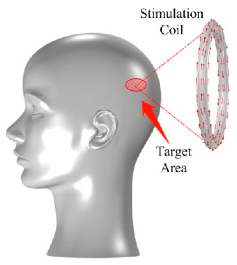
2.1. Principle of the Transcranial Magnetic Stimulation

Transcranial magnetic stimulation is a non-invasive diagnostic and therapeutic technique that is based on the current induced by an applied magnetic field. In comparison with the implanted electrode, TMS can avoid skin injury while penetrating deep inside the tissue. Based on previous research on nerve cells, the resting membrane potential of nerve cells is stable, and it is determined using potassium ion channels, chloride ion channels, and sodium ion channels. The status of these ion channels can be changed by magnetic field stimulation, resulting in a depolarization caused by the induced current. The action potential is invoked when the induced current exceeds the neuron threshold. Thus, the nervous disorder in the brain can be stimulated and alleviated.
Based on this principle, the fundamental structure of TMS is shown in Figure 1. The coil should be placed close to the patient’s cortex during the stimulation. The frequency and intensity of the stimulation are controlled by the signal generator, where the stimulation area is limited by the coil. Thus, to enhance the performance of TMS, both these key parts need to be studied.

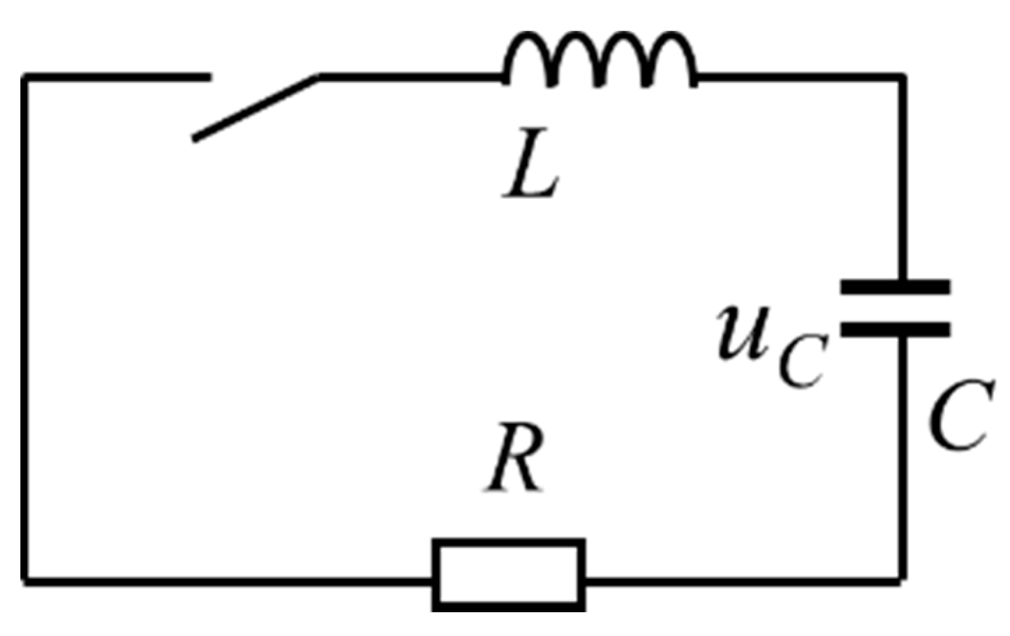
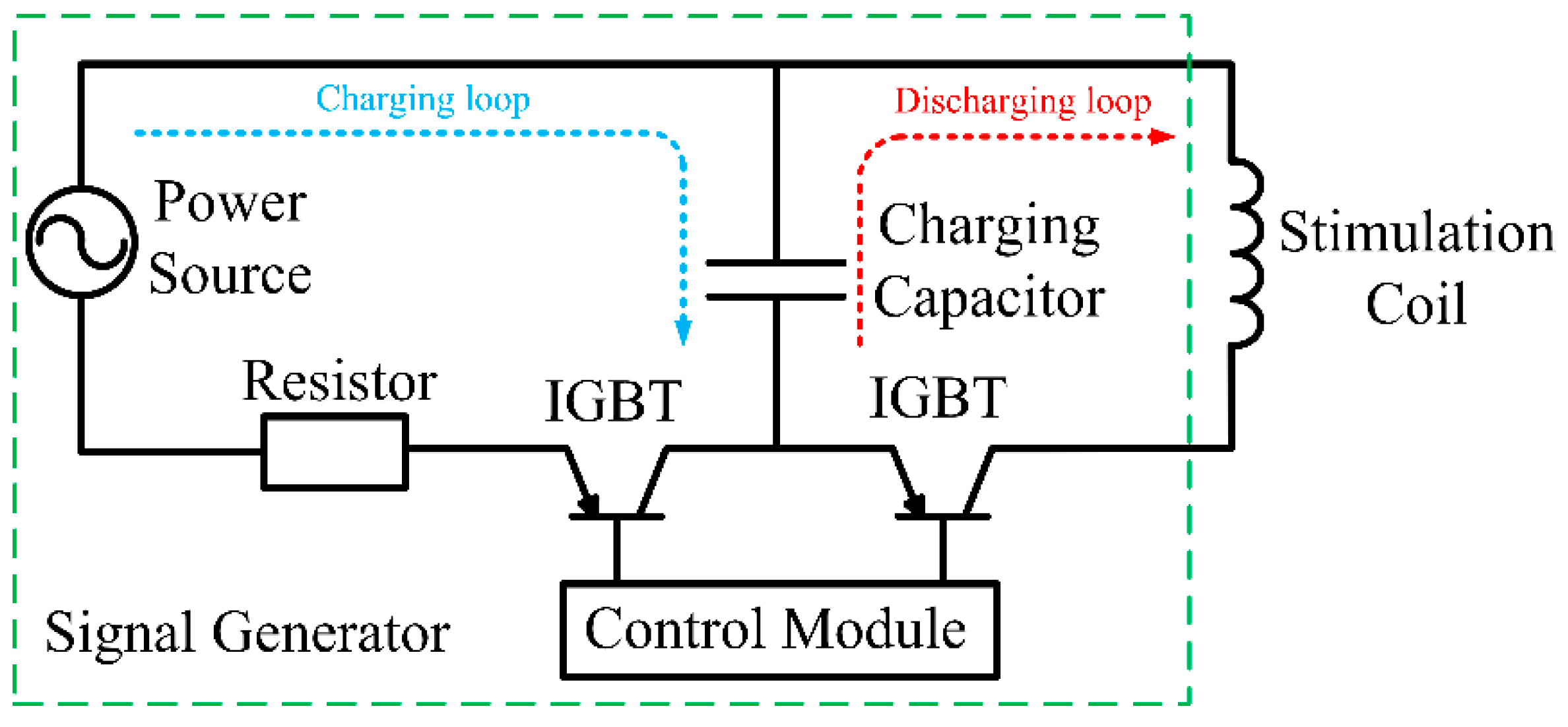
2.2. Design of the Signal Generator

Basically, the main function of the signal generator is to generate the appropriate current for the stimulation coil. For nerve cell stimulations, if the nerve excitation is induced by magnetic stimulation, the next excitation not occurs until the refractory period has passed. Considering the refractory period of human nerve cells, the inter-pulse intervals should not be less than a refractory period of 1.28 ± 0.22 milliseconds [10]. According to research on the relationship between the sensory nerve threshold and the pulsed current frequency of the induced electric field, the pulsed current frequency is set up to 13 kHz.
The principal diagram of the signal generator is shown in Figure 2. Based on Kirchhoff’s voltage law, the circuit of the second-order system can be described by Equation (1):
L C d 2 u c d t 2 + R C d u c d t + u c = 0
where L is the inductance of the coil, C is the capacitance, R is the resistance, and uc is the voltage of the charging capacitor.
The solution of Equation (1) can be solved as Equation (2):
u c = U 0 ω 0 ω e δ t sin ( ω t + β )
where δ = R / 2 L , ω 2 = 1 / L C ( R / 2 L ) 2 , ω 0 = δ 2 + ω 2 and β = arctan ( ω / δ ) .
Additionally, the current in the inductor can be calculated by Equation (3):
i = U 0 ω L e δ t sin ( ω t )
where ω is the angular frequency and δ is the damping coefficient.
According to Equation (3), the waveform of the current is the decaying sinusoidal, and the rest of the energy needs to be dissipated. Therefore, a power resistor is combined with the signal generator.
As shown in Figure 3, the signal generator consists of a charging loop and a discharging loop. The loop is controlled by a control microprocessor, an insulated gate bipolar translator (IGBT), a power resistor, and a capacitor. The capacitor is charged by the power source. When the charging procedure is finished, the processor switches the capacitor to the discharge loop through the IGBT for the magnetic stimulations.

3. The Design of an Innovative Coil for Magnetic Stimulation

The design of the stimulation coil for the TMS system should take many issues into consideration. As mentioned in Section 2, to obtain the supraliminal stimulus, the induced current should not be less than the neuron threshold. Moreover, for a stronger stimulus, the coil should be designed with larger dimensions. However, the required higher focality requires a coil with a smaller diameter. Therefore, the stimulation coil should be subjected to a strength-focality trade-off.

3.1. Calculation of the Electromagnetic Fields

The stimulation coil can be regarded as many single-turn coils. The magnetic flux density can be determined by Biot–Savart’s law [11] in Equation (4).
B = μ 0 4 π C i ( t ) d l × r | r | 3
where μ0 is the permeability, dl is a vector along the path C whose magnitude is the length of the differential element of the wire in the direction of current, l is a point on path C, and r′ = rl is the full displacement vector from the wire element dl at point l to the point at which the field is being calculated (r).
Due to the similar permeability of the air and the nerve cells, the electric field in the nerve cells can be calculated by Equation (5):
E = A t φ
where A is the magnetic vector potential, φ is the scalar potential, and E is the induced electric field strength.
The magnetic vector potential is then simplified by Equation (6):
A = μ 0 N i ( t ) d l 4 π R
where N is the turns of the stimulation coil and R is the radius of the coil. i(t) is the current in the coil.
Therefore, the induced electric field can be expressed by Equation (7):
E = μ 0 N 4 π ( i ( t ) t / R ) d l
The distribution of the electromagnetic field can be obtained based on Equations (4)–(7) by programming in MATLAB. The core code of the loop calculation is to calculate the integration. In this research, the single turn of the coil was divided into 41 parts. After loop calculation, the electric field can be calculated. To verify the calculation by MATLAB programming, the simulation model based on the finite element method (FEM) was been carried out based on Equation (8) [12].
× × ( μ 0 1 μ r 1 A ) + ( j ω σ ω 2 ε 0 ε r ) A + ( σ + j ω ε 0 ε r ) φ = 0
where σ represents the electrical conductivity tensor, ε 0 is the permittivity of vacuum, and ε r is the permittivity of tissue. The boundary of the simulation area is defined as an open-domain, where A = 0.
As can be seen from Figure 4, the coil was modeled in three dimensions. The diameter of the proposed coil was set to the mean diameter of the prototype and simplified with uniform multi-turn coils. When the boundary conditions, the excitation conditions, and the material parameters were set up, the distribution of the electromagnetic field could be calculated by solving the Maxwell equations based on FEM.

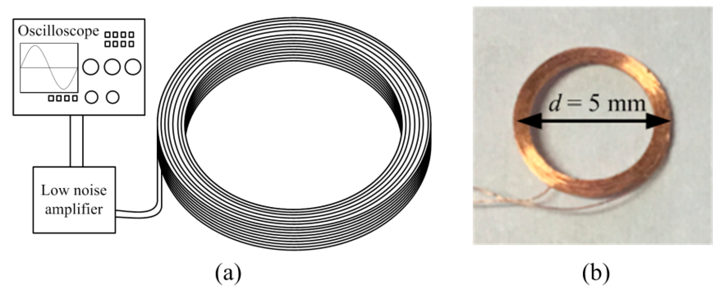
3.2. Measurement of the Field Distribution

A measurement coil is proposed to measure the magnetic field distribution in Figure 5.
As expressed in Equation (9), the Root-Mean-Square (RMS) value of the magnetic field strength can be expressed in terms of the RMS value of the induced voltage in the measurement coil:
H = E 2 π f μ 0 S N
where H is the RMS value of the magnetic field strength, E is the RMS value of the induced voltage in the measurement coil, f is the frequency of the magnetic field, S is the cross-sectional area of the measurement coil, and N is the number of turns of the measurement coil.

3.3. Design of the Stimulation Coil

According to the objectives of medical research, the most common target of TMS is the cortex, which means that the minimal strength of the induced electrical field at a location of 15-mm depth should not be less than 40 V/m. Thus, to meet the requirements and achieve higher performance, the coils are designed in quad coil form and arranged in X-shape. The function of the little coils is to improve the focality of the stimulations and that of the big coils is to intensify the strength of the stimulation. Figure 6 shows the structure of the proposed coil from the front and top views, and the parameters of the coil are listed in Table 1.
Figure 7 shows the prototype of the proposed coil for TMS. A polymethyl methacrylate (PMMA) holder was designed and used to secure the coil. As shown in Figure 8, for a more accurate simulation of the electromagnetic field, a three-dimensional human head model is established. Different tissues are reflected in the model by multilayers.
According to previous research, the electromagnetic properties of the tissues are listed in Table 2 [13].

4. Theoretical Analysis and Field Distribution

In this section, the distributions of the electromagnetic fields of typical coils and the proposed coil are simulated and compared. The strength of stimulation and the focality are also analyzed. Moreover, the influence of the key factors, such as the diameter and the intersection angle, are discussed for further optimization.

4.1. Analysis of the Field Distribution and Verifications

According to the parameters of the signal generator, the stimulation voltage is set at 680 A, and the pulsed current frequency is set at 13 kHz. A comparison between the measurements and the numerical calculations of the magnetic flux density is shown in Figure 8. During the experiment, the measurement coil was placed on a measurement platform with the scale line.
The calculated maximum magnetic flux density at the target nerve location (8 cm beyond the coil plane) was 26.1 mT, and the measured magnetic flux density by the measurement coil was 27.2 mT. The experimental results showed that the measured values agreed well with the calculated results from the simulations as illustrated in Figure 9.

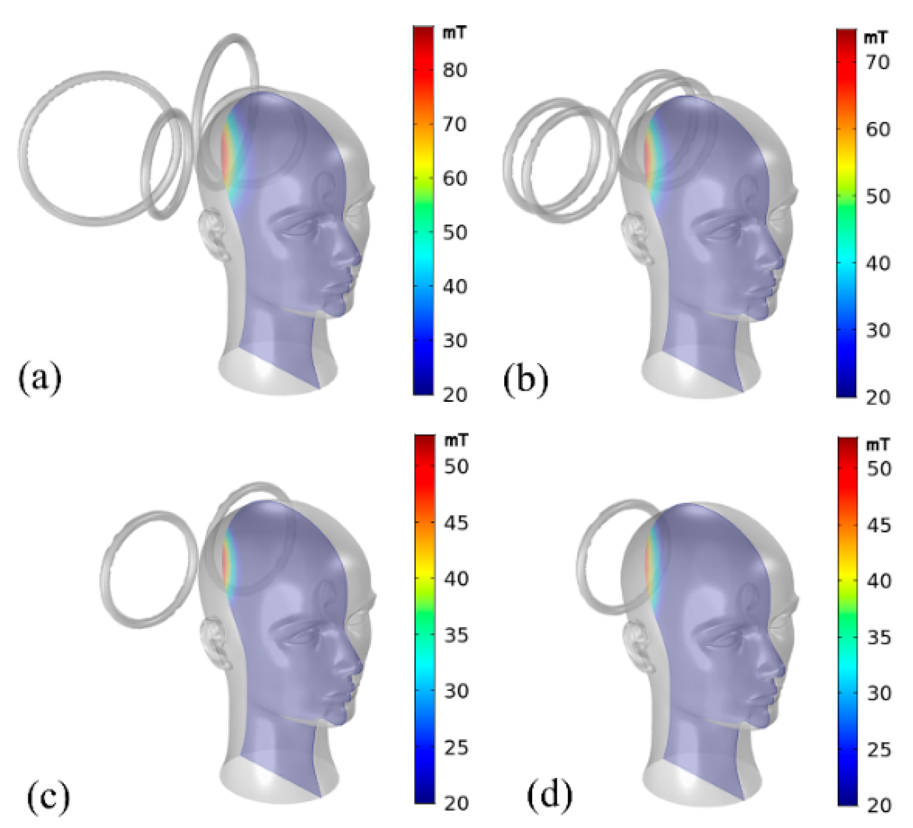
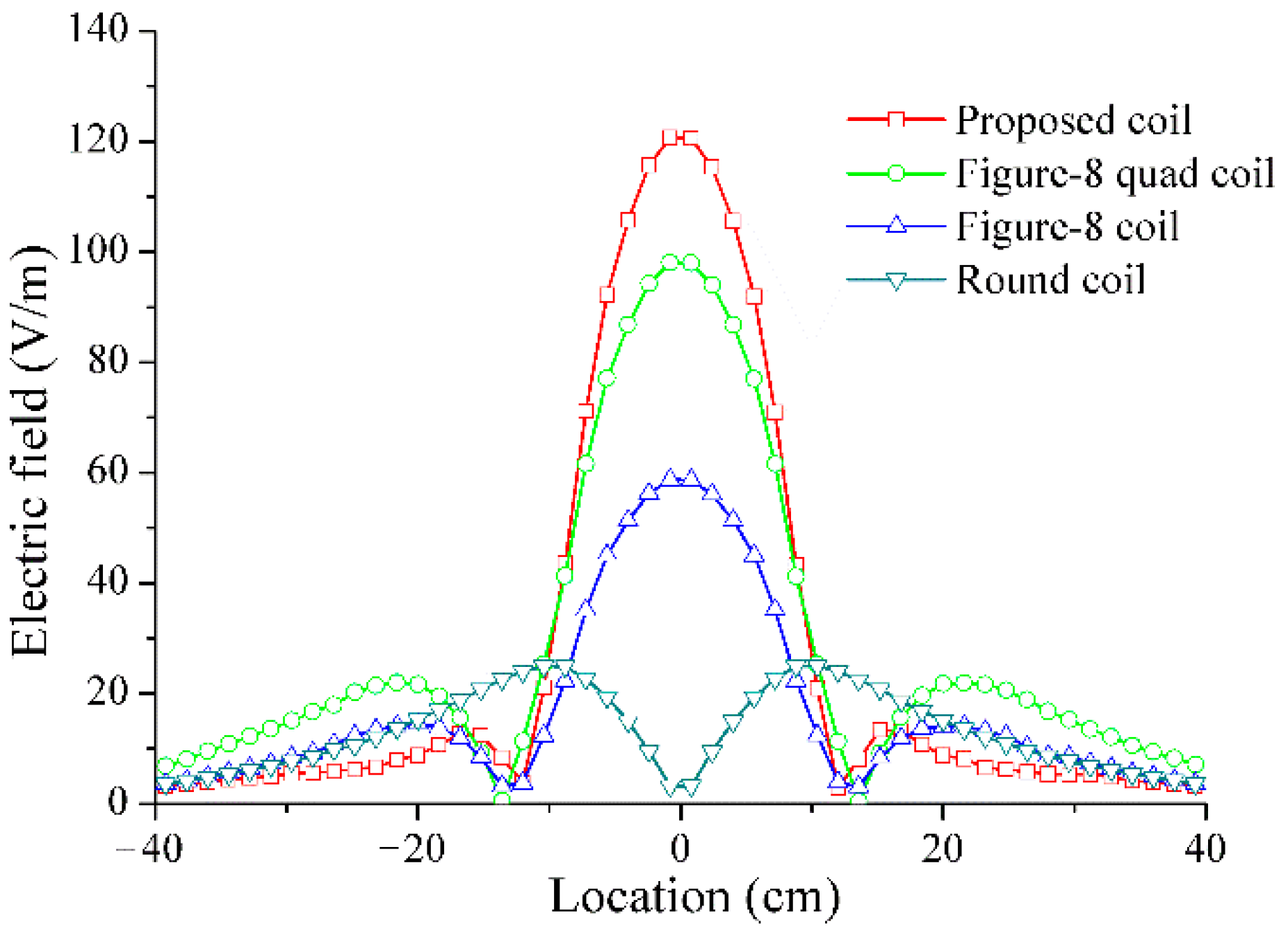
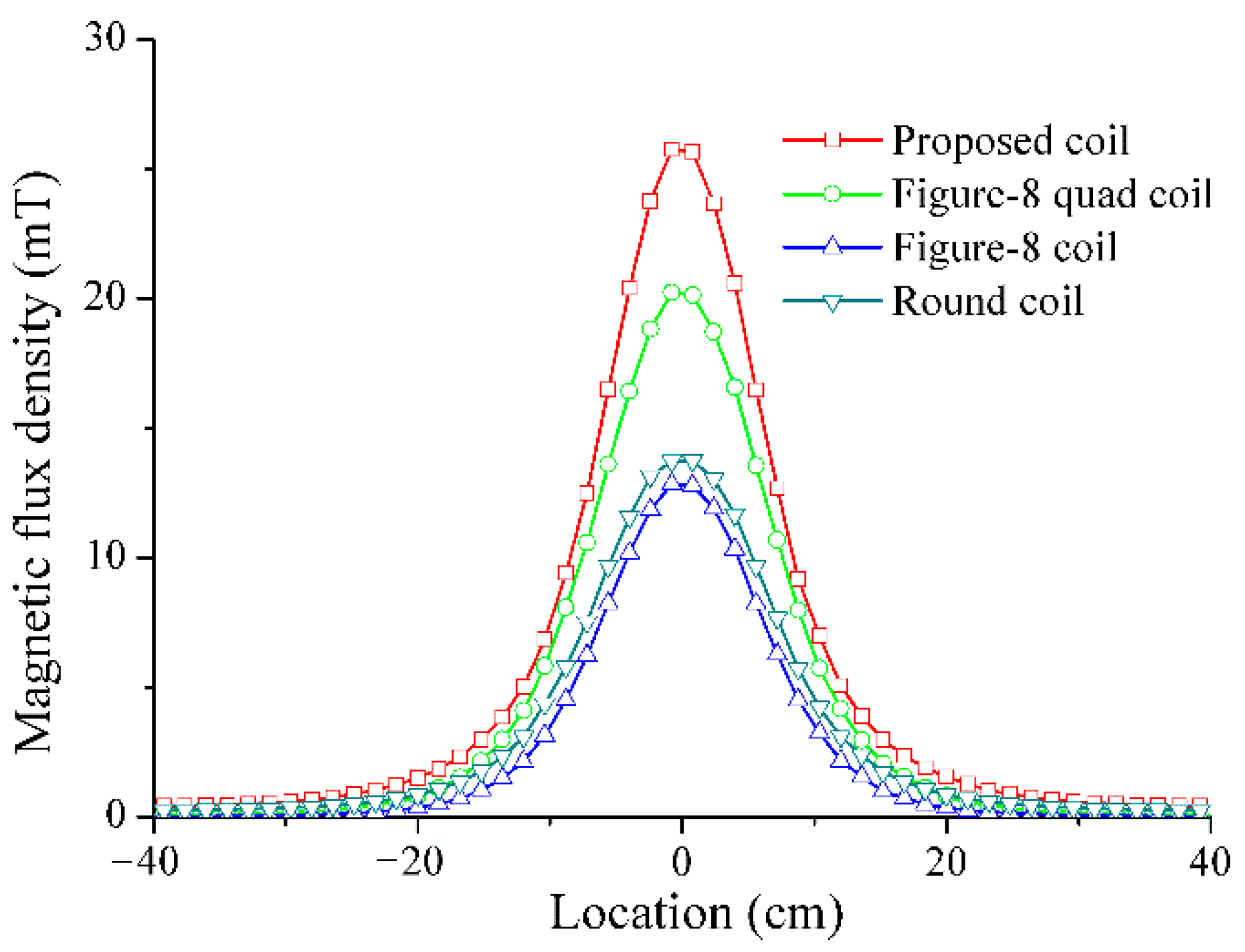
4.2. Comparison of the Typical Performances

In this research, four different stimulation coils were compared. Figure 10 shows a comparison of the distribution of the magnetic flux densities, respectively, for the proposed coil, a figure-8 quad coil, a figure-8 coil, and a regular round coil, where the four coils had the same diameter and excitation signal. The results showed that the proposed coil achieves a higher stimulation intensity and depth.
In terms of the induced electric field, the distributions of the electric field are simulated by Equation (7). As shown in Figure 11, the electrical field strength of the proposed coil at 8 cm beyond the coil plane is better than that of the other three coils.
Another comparison of the four coils (8 cm beyond the coil plane) when it comes to the magnetic flux density was carried out. As illustrated in Figure 12, the maximum value of the magnetic flux density of the proposed coil was 26.1 mT and the figure-8 quad coil, figure-8 coil, and round coil were 20.4 mT, 13.0 mT, and 13.9 mT, respectively.
The focality is evaluated by the full width at half maximum (FWHM) [14]. FWHM is a parameter that is commonly used to describe the level of power concentration. It is given by the distance between the points on the curve, which is greater than 1 / 2 (3 dB decay point) of its maximum magnitude.
As shown in Figure 13, the FWHM of the electrical field of the different coils beyond the coil plane close to the cortex is proposed. With the increase in the depth inside the brain, the proposed coil has the smallest FWHM (lower is better).
A comparison of the electric fields at different stimulation depths is shown in Figure 14. For the same stimulation depth, the proposed coil could induce a higher electric field.
The comparison between FWHM, electric field, and magnetic flux density of the four types of coil at the same depth is shown in Table 3. According to the performed simulations and comparisons, the results show that the proposed coil has the highest field strength and best focality.

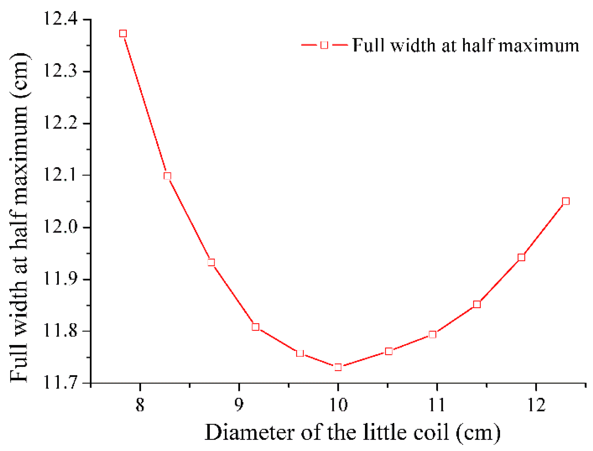
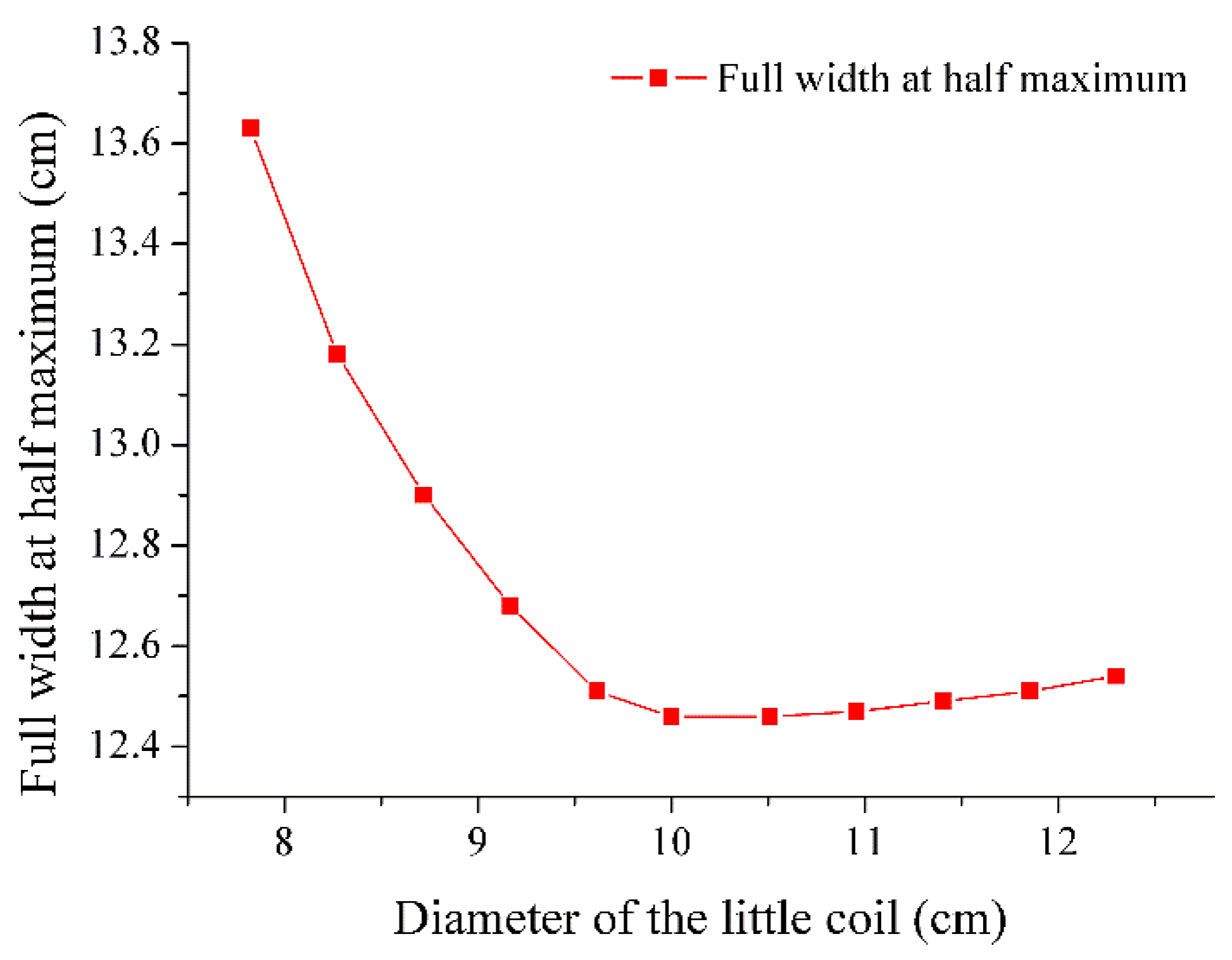
4.3. The Simulation of the Influential Factors

With the variation in the parameters of the coil, the electromagnetic field distribution can also be changed. Therefore, it is necessary to analyze the influence of the typical parameters for further optimizations. As shown in Figure 15, at the location 8 cm beyond the coil plane, with the increase in the diameter of the little coil, the FWHM of the electric field decreases and reaches a peak of 10 cm. When the diameter of the little coil increases by more than about 10 cm, the FWHM increases again with the diameter. Therefore, the lowest FWHM is obtained for a coil diameter of approximately 10 cm.
Besides, other distances beyond the coil plane, such as 7 cm and 9 cm, are also simulated. As shown in Figure 16 and Figure 17. The trend is similar to the previous case where the distance is 8 cm. When the distance approaches 2 cm beyond the coil plane, the simulations show that the diameter of 9 cm has the lowest FWHM. However, the distance of 2 cm from the head to the coil is too close. Therefore, in this research, from a practical standpoint, the little coil of diameter 10 cm has the lowest FWHM.
Moreover, the FWHM of the electric field is also influenced by the intersection angle between the big and little coils. As shown in Figure 18, the shape of the curve is similar to the curve in Figure 14. Thus, at the location of 8 cm beyond the coil plane, the FWHM of the electric field is lowest when the intersection angle is around 53 degrees.
The simulations show that the focality of the coils is sensitive to the diameter of the little coils and the intersection angle of the coil planes. The stimulation strength can still be enhanced by increasing the diameter of the big coils, but the trade-off of its inductance increases and the degradation of the focality should not be neglected.

5. Conclusions

In this research, an innovative coil that has a quad coil form was proposed for TMS. As simulated by the finite element method, the electromagnetic field distribution and the focality were studied and verified by the measurements. According to the analysis in Section 4, in comparison with typical stimulation coils, the proposed coil has shown higher stimulation strength and a better focality. Besides, the influence of the diameter and the intersection angle of the coils are discussed for further optimization. Thus, this approach not only suggests a new way of designing coils for TMS, but also helps to understand the trade-off between the influential factors and the performance of the stimulation coils.

Author Contributions

Conceptualization, N.Z., S.W., and S.N.; data curation, N.Z.; formal analysis, N.Z. and S.N.; funding acquisition, S.W. and N.Z.; investigation, Z.W., J.S., and N.Z.; methodology, Z.W., Y.Z., and N.Z.; project administration, S.W., N.Z., and S.N.; software, N.Z., S.W., and Z.W.; supervision, S.W. and S.N.; validation, H.Q.; visualization, N.Z. and Z.W.; writing—original draft preparation, Z.W. and N.Z. All authors have read and agreed to the published version of the manuscript.

Funding

This research was funded in part by the National Natural Science Foundation of China (51807159); China Postdoctoral Science Foundation (2017M620456, 2019M653635); Natural Science Basic Research Plan in Shaanxi Province of China (2019JQ-229, 2019JM-308); the Fundamental Research Funds for the Central Universities (xjj2018232); the Scientific Research Funds for New Teacher of Xi’an Jiaotong University (DQ6K004); the Young Talent Fund of University Association for Science and Technology in Shaanxi (20200113); and the Scientific Research Program of Shaanxi Provincial Education Department (20JG003).

Institutional Review Board Statement

Not applicable.

Informed Consent Statement

Not applicable.

Data Availability Statement

Not applicable.

Acknowledgments

Thanks are due to Bolan Lai for assistance with the data curation and validation.

Conflicts of Interest

The authors declare no conflict of interest.

References

  1. Shimizu, T.; Hosomi, K.; Maruo, T.; Goto, Y.; Shimokawa, T.; Haruhiko, K.; Saitoh, Y. Repetitive transcranial magnetic stimulation accuracy as a spinal cord stimulation outcome predictor in patients with neuropathic pain. J. Clin. Neurosci. 2018, 53, 100. [Google Scholar] [CrossRef] [PubMed]
  2. Seewoo, B.J.; Feindel, K.W.; Etherington, S.J.; Rodger, J. Resting-state fMRI study of brain activation using low-intensity repetitive transcranial magnetic stimulation in rats. Sci. Rep. 2018, 8, 6706. [Google Scholar] [CrossRef] [PubMed]
  3. Goede, A.A.G.; Braack, E.M.T.; Putten, M.J.A.M.V. Single and paired pulse transcranial magnetic stimulation in drug naïve epilepsy. Clin. Neurophysiol. 2016, 127, 3140. [Google Scholar] [CrossRef] [PubMed]
  4. Lee, E.G.; Duffy, W.; Hadimani, R.L.; Waris, M.; Siddiqui, W.; Islam, F.; Rajamani, M.; Nathan, R.; Jiles, D.C. Investigational Effect of Brain-Scalp Distance on the Efficacy of Transcranial Magnetic Stimulation Treatment in Depression. IEEE Trans. Magn. 2016, 52, 5000804. [Google Scholar] [CrossRef]
  5. Yang, S.; Xu, G.; Wang, L.; Ge, Y.H.; Yu, H.L.; Yang, Q.X. Circular coil array model for transcranial magnetic stimulation. IEEE Trans. Appl. Supercon. 2010, 20, 829. [Google Scholar] [CrossRef]
  6. Li, J.T.; Liang, Z.; Ai, Q.; Yan, X.H.; Tian, J. Double Butterfly Coil for Transcranial Magnetic Stimulation Aiming at Improving Focality. IEEE Trans. Magn. 2012, 48, 3509. [Google Scholar] [CrossRef]
  7. Liu, C.; Zhu, J.Y.; Li, J.T.; Wang, S.H.; Qiu, J.; Shi, Q.D.; Liu, J.X.; Zhong, L.S.; Zhu, J.G. Functional Magnetic Stimulation System and Pulsed Magnetic-Field Effect on Peripheral Nerve. IEEE Trans. Magn. 2013, 49, 1853–1856. [Google Scholar] [CrossRef]
  8. Zhang, N.M.; Wang, S.H.; Chen, X.L.; Shi, Q.D.; Li, J.T.; Zhu, J.Y.; Wang, S.; Yang, B.; Guo, Y.G.; Zhu, J.G. Study on Neural Regeneration Effect of Rat by Using Pulsed Functional Magnetic Stimulation. IEEE Trans. Magn. 2015, 51, 1–4. [Google Scholar] [PubMed] [Green Version]
  9. Deng, Z.D.; Lisanby, S.H.; Peterchev, A.V. Electric field depth-focality tradeoff in transcranial magnetic; stimulation: Simulation comparison of 50 coil designs. Brain Stimul. 2013, 6, 1–13. [Google Scholar] [CrossRef] [PubMed] [Green Version]
  10. Davey, K.; Riehl, M. Designing transcranial magnetic stimulation systems. IEEE Trans. Magn. 2005, 41, 1142. [Google Scholar] [CrossRef] [Green Version]
  11. Grant, I.S.; Phillips, W.R. Electromagnetism, 2nd ed.; Manchester Physics; John Wiley & Sons: Hoboken, NJ, USA, 2008. [Google Scholar]
  12. Salvador, R.; Miranda, P.C.; Roth, Y.; Zangen, A. High permeability cores to optimize the stimulation of deeply located brain regions using transcranial magnetic stimulation. Phys. Med. Biol. 2009, 54, 3113. [Google Scholar] [CrossRef] [PubMed]
  13. Gabriel, C.; Gabriel, S.; Corthout, E. The dielectric properties of biological tissues: I. Literature survey. Phys. Med. Biol. 1996, 41, 2231. [Google Scholar] [CrossRef] [PubMed] [Green Version]
  14. Koponen, L.M.; Nieminen, J.O.; Ilmoniemi, R.J. Minimum-energy coils for transcranial magnetic stimulation: Application to focal stimulation. Brain Stimul. 2014, 8, 124. [Google Scholar] [CrossRef] [PubMed] [Green Version]
Figure 1. Principle of the transcranial magnetic stimulation (TMS).
Applsci 11 01960 g001
Figure 2. Circuit diagram of the signal generator.
Applsci 11 01960 g002
Figure 3. Framework of the TMS system including insulated gate bipolar translator (IGBT).
Applsci 11 01960 g003
Figure 4. 3D model of the proposed coil and the human head.
Applsci 11 01960 g004
Figure 5. (a) Structures of the measurement coil and (b) prototype of the measurement coil.
Applsci 11 01960 g005
Figure 6. (a) Front view of the proposed coil, (b) top view of the proposed coil, and (c) the location of the compared plane (8 cm beyond the coil plane).
Applsci 11 01960 g006
Figure 7. The prototype of the proposed coil for TMS.
Applsci 11 01960 g007
Figure 8. Structures of the human head with multilayers.
Applsci 11 01960 g008
Figure 9. Comparison of the measurements and the simulated calculations of the magnetic flux density.
Applsci 11 01960 g009
Figure 10. Comparison of the magnetic flux density distribution between the proposed coil and the typical coils. (a) The proposed coil, (b) figure-8 quad coil, (c) figure-8 coil, and (d) round coil.
Applsci 11 01960 g010
Figure 11. Comparison of the electrical field between the four coils.
Applsci 11 01960 g011
Figure 12. Comparison of the magnetic flux density between the four coils.
Applsci 11 01960 g012
Figure 13. Comparison of the full width at half maximum (FWHM) between the four coils.
Applsci 11 01960 g013
Figure 14. Comparison of the electric fields at different stimulation depths.
Applsci 11 01960 g014
Figure 15. Comparison of FHWM between the different diameters of the little coil.
Applsci 11 01960 g015
Figure 16. Simulation of FWHM at 7 cm beyond the coil plane.
Applsci 11 01960 g016
Figure 17. Simulation of FWHM at 9 cm beyond the coil plane.
Applsci 11 01960 g017
Figure 18. Comparison of FHWM between the different intersection angles of the big-little coils.
Applsci 11 01960 g018
Table 1. Parameters of the proposed coil.
Big-CoilsLittle-Coils
Turns1210
Coil diameter15.6 cm10 cm
Wire radius0.3 cm0.3 cm
Table 2. Electromagnetic properties of the human head model.
Conductivity
(S/m)
Permittivity
(F/m)
Permeability
(H/m)
Depth
(mm)
Skin0.4651.2 × 10413
Skull0.010.8 × 104110
Cerebrospinal Fluid1.6540.6 × 10412
Brain0.1261.2 × 104130
Table 3. The comparison of the four types of the coil at the same depth (8 cm beyond the coil plane).
Electrical Field
(V/m)
Magnetic Flux Density
(mT)
FWHM
(cm)
Proposed coil120.626.111.7
Figure-8 quad coil97.920.412.3
Figure-8 coil58.713.011.9
Round coil3.313.914.7
Publisher’s Note: MDPI stays neutral with regard to jurisdictional claims in published maps and institutional affiliations.

