
Plume Divergence and Discharge Oscillations of an Accessible Low-Power Hall Effect Thruster

Mechanical and Aerospace Engineering Department, Western Michigan University, Kalamazoo, MI 49008, USA
*
Author to whom correspondence should be addressed.
Appl. Sci. 2021, 11(4), 1973; https://0-doi-org.brum.beds.ac.uk/10.3390/app11041973
Submission received: 23 December 2020
/
Revised: 29 January 2021
/
Accepted: 19 February 2021
/
Published: 23 February 2021
(This article belongs to the Special Issue Plasmas for Space Propulsion)
Abstract
:Hall effect thrusters (HETs) are an increasingly utilized proportion of electric propulsion devices due to their high thrust-to-power ratio. To enable an accessible research thruster, our team used inexpensive materials and simplified structures to fabricate the 44-mm-diameter Western Hall Thruster (WHT44). Anode flow, discharge voltage, magnet current, and cathode flow fraction (CFF) were independently swept while keeping all other parameters constant. Simultaneously, a Faraday probe was used to test plume properties at a variety of polar coordinate distances, and an oscilloscope was used to capture discharge oscillation behavior. Plasma plume divergence angle at a fixed probe distance of 4.5 thruster diameters increased with increasing anode flow, varying from 36.7° to 37.4°. Moreover, divergence angle decreased with increasing discharge voltage, magnet current, and CFF, by 0.3°, 0.2°, and 8°, respectively, over the span of the swept parameters. Generally, the thruster exhibited a strong oscillation near 90 kHz, which is higher than a similarly sized HET (20–60 kHz). The WHT44 noise frequency spectra became more broadband and the amplitude increased at a CFF of less than 1.5% and greater than 26%. Only the low flow and low voltage operating conditions showed a quiescent sinusoidal discharge current; otherwise, the discharge current probability distribution was Gaussian. This work demonstrates that the WHT44 thruster, designed for simplicity of fabrication, is a viable tool for research and academic purposes.
1. Introduction
Hall effect thrusters (HETs) are a subcategory of in-space electric propulsion devices that harness electric energy to accelerate a gas to provide thrust [1]. For in-space applications, the electrical energy is typically acquired by solar panels and stored in batteries. That energy is then converted into charged particle kinetic energy through the use of carefully designed magnetic and electric fields. The primary advantages to utilizing HETs are high propellant exhaust velocities and high thrust-to-power ratios [2]. Exhaust velocities for HETs utilizing xenon propellant are typically between 10 and 20 km/s, resulting in high specific impulses () and thus, increasing the change in velocity () a spacecraft can achieve for a given propellant mass [1]. This enables a spacecraft propulsion system to produce a greater net impulse for a set propellant mass, or, conversely, reduces the necessary propellant for a given mission allowing increased payload mass. Albeit relatively low compared to conventional chemical propulsion, the thrust produced by an HET is sufficient to perform satellite station-keeping, slow orbit transfers, and attitude control maneuvers. Modern mission concepts are even utilizing HETs for deep space exploration missions [3].
The Western Hall Thruster, with a 44-mm outer diameter channel wall (WHT44), was designed as a 200 W nominal testing platform by an undergraduate capstone group in 2015/16. Details regarding the design and initial characterization experiment can be found in references [4,5], and a brief overview of the design process will be described here. The WHT44 has a channel width of 5 mm and a channel anode-to-exhaust plane length of 14 mm. The goal of the original project was to demonstrate that an HET could be designed, simulated, and manufactured using resources available to a wider number of university students outside of the very high research activity (R1 Carnegie classification), and well funded institutions. The SPT-70 was used as the baseline, and dimensions were initially scaled down before parameterization began in COMSOL Multiphysics software to achieve the desired magnetic lens shape [6]. This desired magnetic lens was achieved by iterating the parametric model in order to emulate the field line shape and centerline strength profile given in reference [1]. The predominate magnetic circuit material and geometry were select to prevent saturation and to minimize cost. The WHT44 discharge anode doubles as both an electrode and as a propellant gas injection manifold. Propellant injected into the discharge channel is done so that the propellant is azimuthally uniform prior to reaching the ionization region of the discharge channel. The magnetic circuit, anode, and discharge channel were machined and assembled in-house at no cost to the project. The WHT44 was completed with a budget of under $2100, including an allotment for xenon gas to perform initial characterization testing.
1.1. Theory of Operation
1.1.1. Hall Effect Thruster
HETs are electrostatic propulsion devices consisting of a hollow cathode, a discharge channel with an anode, and a system to generate a magnetic field radial to the discharge channel. Electrons are inhibited from traveling from the cathode to the anode by the radial magnetic field and, instead, form an azimuthal Hall current in the ExB direction. This Hall current ionizes the neutral propellant injected through the anode into the discharge channel. The more massive ions are mostly unaffected by the radial magnetic field and are instead accelerated by the axial electric field.
While HETs are mechanically simple and classified as electrostatic devices, they rely upon complex plasma physics and magnetic field topologies to operate. HETs exhibit several oscillatory modes over a wide range of frequencies, from 1 kHz to 60 MHz [7]. The effects of these oscillation modes on thruster lifetime, thrust, and efficiency are not fully understood. The two most studied oscillation modes are the breathing mode and the azimuthal spoke mode. The breathing mode is an ionization driven oscillation from the predator-prey relationship between neutral atoms and ions in the plasma plume. According to reference [7], we should expect to see these oscillations at frequencies between 15–35 kHz. Breathing mode oscillation frequencies, , can be modeled in 1-dimension by solving a form of Lotka-Volterra’s predator-prey equations, resulting in Equation (1).
where is the ionization zone length, and and are the ion and neutral velocity, respectively [8,9]. Spoke mode oscillations, when identified with high-speed cameras, are regions of higher plasma light intensity, indicative of an ionization front, most often traveling in the direction at velocities around 1 km/s [10,11].
1.1.2. Faraday Probe
Faraday probes are a common diagnostic for determining ion flux in plasma plumes from electric propulsion devices. They are used to quantify thruster beam divergence, identify asymmetric behavior, determine total integrated beam current, and identify various utilization efficiencies (i.e., mass utilization, current utilization, and beam utilization). Faraday probe data can also be collected at a variety of facility background pressures in order to attempt extrapolation of the results to flight-like operation [12]. Fundamentally, Faraday probe data are collected through the use of a planer surface electrode of known area, , oriented using a cylindrical or spherical coordinate system. A cylindrical coordinate system is one wherein the probe is mounted parallel to the thruster’s axial centerline and swept radially. This can be accomplished with either one or two linear stages mounted orthogonally with respect to the thrust axis. In a hemispherical coordinate system, the probe is mounted on a rotary stage such that the probe is always facing in the direction of the thruster center point, a point created by the intersection of the thruster discharge exit plane and the thruster centerline. A hemispherical arrangement was used exclusively for this study. The Faraday probe is biased negatively such that it is in the linear ion saturation regime of the plasma. Repeatedly repositioning the probe and collecting data gives the operator a current density contour of the thruster plume [12].
Facility interactions that influence ion current density are present in any ground based experiment. There are two primary interaction mechanisms that exist during ground based testing related to background neutrals in the vacuum facility. First, background neutrals may be ingested into the thruster, ionized, and accelerated, creating excess thrust. Second, charge exchange (CEX) collisions occur when fast ions strike slow neutrals to produce slow ions. CEX collisions scatter beam ions and have the effect of increasing current density in the plume periphery. This results in an increased plume divergence that would not otherwise be present in a space environment. Additionally, corrections due to secondary electron emission (SEE) from the probe collector surface, probe geometry, and thruster distance must be made to avoid excessive error in the analyzed results from Faraday probe data. Reference [12] was utilized substantially for analysis of the Faraday probe data collected in this experiment, and we convey the primary processing methods in the following paragraphs.
Current density, j, was calculated by
is a correction factor that accounts for probe geometry, and is a correction factor that accounts for SEE as a result of ion charge species impacting the tungsten probe surface. is the current to the Faraday probe, and is the Faraday Probe collector area. An ExB probe (Wein filter) was unavailable for charge species analysis of the WHT44, so the , was assumed to consist only of . The total beam current, , and the component of the beam current in the axial direction, , are calculated using Equations (3) and (4), respectively.
where R is the radial distance between the Faraday probe and the thruster centerline, and is a piecewise function defined as
where is the probe angle, is the thruster diameter, and W is the discharge channel width. The beam divergence half-angle, , is defined as
and and are correction factors for measuring ions coming from a two-point source in a hemispherical coordinate system. corrects for the difference in radii formed due to the fact that the thruster annulus is not an ideal point source. corrects for the change in incidence angle of ions impacting the probe face as angle, , and radius are swept. There is a second method for calculating based on the angle that includes 90% (or 95%) of the total ion current. To maintain consistency between the methods of analysis for the Faraday probe data, Equation (6) was used in this work. The difference between the two methods at varying background pressure and thruster diameter downstream (TDD) was examined for the WHT44 in reference [13]. The method outlined using Equation (6) consistently showed smaller half-angles compared with the method that uses 95% of the total ion current by .
Faraday probe data were used to determine the beam current and the axial component of the beam current using Equations (3) and (4), from which three thruster loss mechanisms are determined. These are the current utilization efficiency, , mass utilization efficiency, , and beam utilization efficiency, defined with Equations (7)–(9).
where
represents the ratio of useful ion beam current to the total discharge current, represents the ratio of the ion mass flow to the total propellant mass flow consumed by the thruster, quantifies the component of the momentum lost due to the plume divergence, is the ion mass, and and are the ion current fraction and charge of the species, respectively.
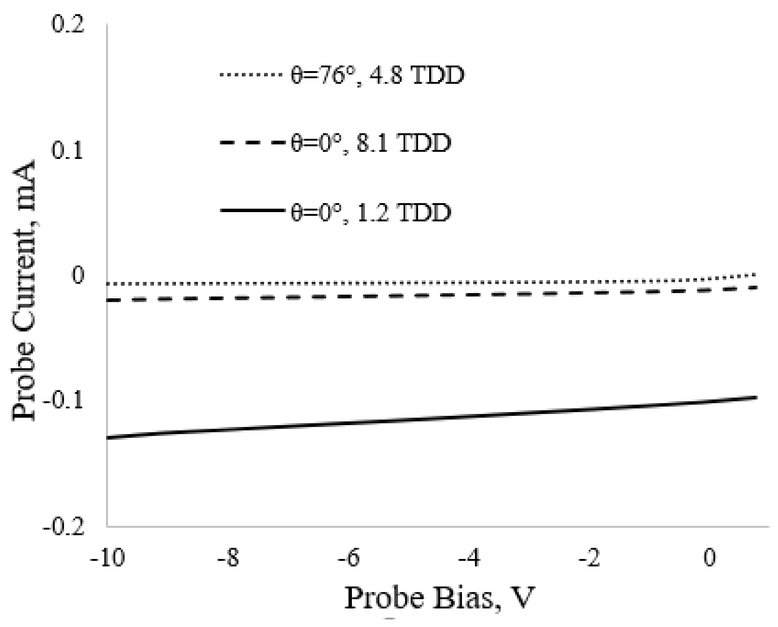
The Faraday probe used for this study had a collector electrode made of tungsten with a diameter of 6.33 mm. The gap distance between the collector and the guard-ring measured 0.835 mm. The guard-ring had an outer diameter of 13 mm with the overall depth of the collector and guard-ring being 10 mm. The probe was biased to −15 V based off of extensive Langmuir probe sweeps that demonstrated ion saturation to occur below 0 V in the plume, as shown in Figure 1.
2. Materials and Methods
The study presented in this manuscript was a sweep study wherein a single thruster parameter was adjusted while holding all other control variables constant and observing the effects. Notably, changes in the the thruster discharge current, high-speed behavior, and plume measurements were recorded at every operational data point. This study was performed over two vacuum chamber evacuations. Under the first evacuation, three sweep studies were performed:
- Discharge voltage was swept from 170 V to 210 V while holding magnet current to 200 mA, anode mass flow rate, , to 1.27 mg/s, and using a cathode flow fraction (CFF) of 20.7%
- Discharge voltage was swept from 170 V to 220 V while holding magnet current to 200 mA, 1.08 mg/s, and using a cathode flow fraction of 20.7%
- Magnet current was swept from 200 mA to 230 mA while holding discharge voltage to 200 V, 1.27 mg/s, and using a cathode flow fraction of 20.7%
CFF is the ratio of the cathode mass flow rate to the anode mass flow rate, .
Under the second evacuation, the CFF was swept from 1.5% to 30.8% while holding discharge voltage to 170 V, magnet current to 200 mA, and xenon anode flow to 1.27 mg/s. The 170 V discharge voltage on the second evacuation was selected to support a concurrent study. A complete summary of the parameterization study and the resulting power levels are shown in Table 1. Parameter limits were selected to keep the total discharge power below 300 W or to keep the thruster from extinguishing, whichever came first. The remainder of this section will describe the experimental facility, test equipment, and data acquisition system used in this study.
2.1. Facility
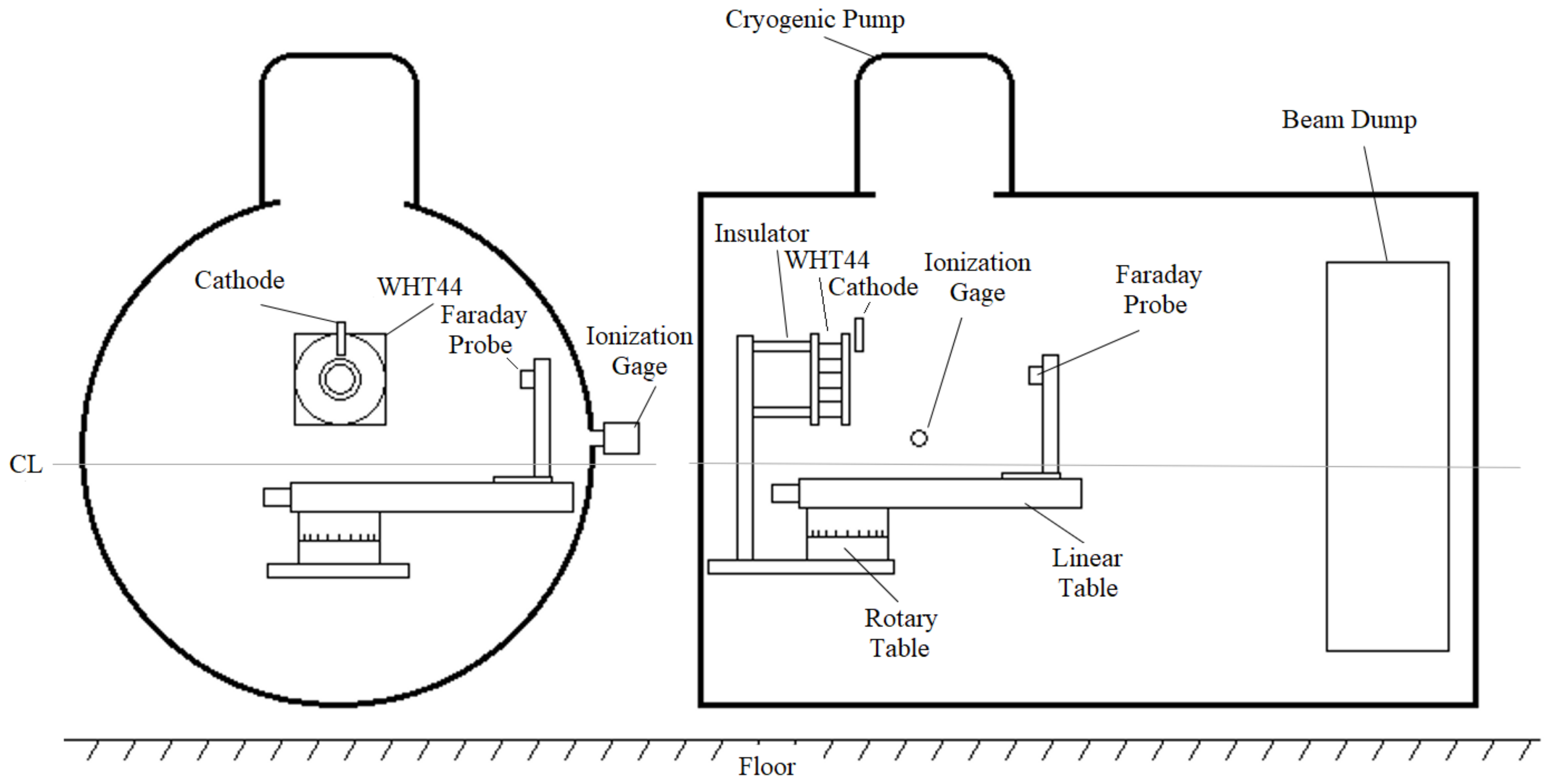
This experiment was performed in the Aerospace Laboratory for Plasma Experiments’ (ALPE’s) vacuum chamber facility at Western Michigan University. The facility is a 1-m-diameter, 1.5-m-long stainless steel chamber. A single CTI-250F cryogenic pump with a capacity of roughly 2000 l/s nitrogen was capable of pumping the facility to a base pressure of 1.5 × 10 Torr-N. Testing was performed at an anode flow set point of either 1.27 or 1.08 mg/s using research grade 99.999% xenon propellant with corresponding facility pressures of 6.1 × 10 and 8.4 × 10 Torr-Xe, respectively. Three laboratory power supplies provided power to the magnets, discharge, and cathode keeper. Xenon flow was controlled to the discharge anode and cathode by two Alicat MCV mass flow controllers calibrated for xenon. Chamber pressure was monitored by a single xenon calibrated ionization gauge. Figure 2 shows a simplified diagram of the experimental setup.
2.2. Thruster
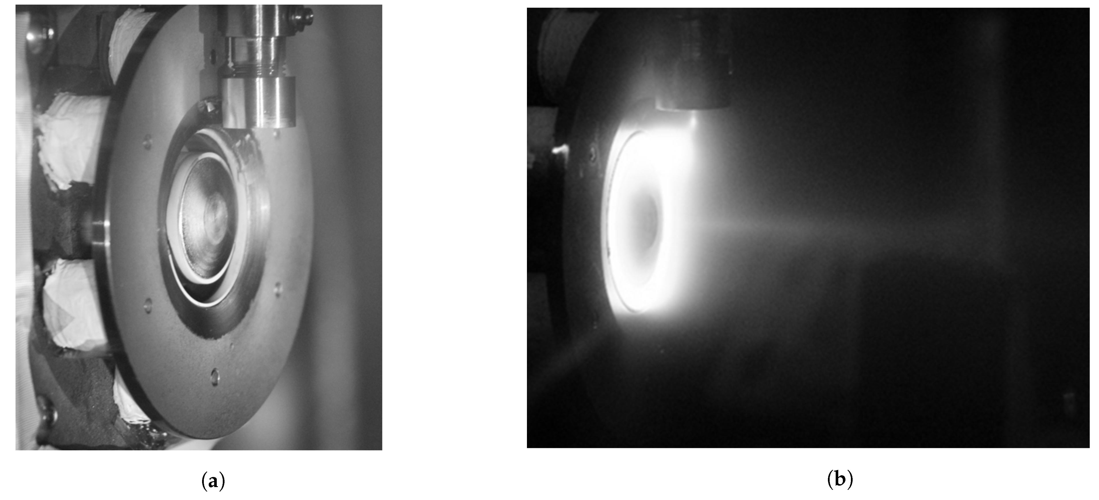
As previously mentioned, two anode flow set points of 1.08 and 1.27 mg/s were used. A 1.6-mm diameter heaterless hollow cathode with a tungsten-ceramic composite insert from Plasma Controls, LLC. was mounted orthogonal to the WHT44. The cathode was mounted at the twelve-o-clock position oriented downward such that the cathode keeper orifice was 30 mm above thruster centerline and 11.6 mm forward of the discharge channel exit plane. This placed the orifice of the cathode inside of the separatrix of the magnetic field. The thruster was operated with a CFF of 20.7% for the varying discharge voltage and varying magnetic field experiments. This CFF is higher than the nominal 7% used for many HETs [14]; however, it was found to be necessary to prevent the thruster discharge from unexpectedly extinguishing. The cathode common and thruster body were electrically tied to ground, as it made thruster startup more consistent. The WHT44 was designed such that the amp-turn ratio of the inner and outer magnet coils allowed for them to be operated in series to generate the desired magnetic field shape. The thruster was located above the vacuum chamber centerline to enable full sweep capability of the Faraday probe axis. Photographs of the WHT44 post-test and operating are shown in Figure 3.
Thermocouples were affixed to the WHT44 back pole and on an outer magnet with ceramic adhesive. Maximum temperatures of 252 C and 214 C were reached at the back pole and outer magnet, respectively. For the duration of testing, cathode keeper current was regulated at 300 mA for added thruster stability and to reduce thruster extinguishing events. Mean discharge current was obtained using a shunt resistor and custom AD210 isolation amplifier sampled at approximately 1 Hz with an Agilent 34980A data acquisition (DAQ) mainframe digital multimeter and 34921A relay mulitplexer. The AC discharge current was monitored using a Pearson coil model 4100 read by a 200 MHz commercially available oscilloscope sampling at 500 MSa/s.
3. Results and Discussion
In this section we share the discharge current behavior and Faraday probe results during the thruster sweep experiments.
3.1. Thruster Performance
As previously mentioned, this study was performed during two vacuum facility evacuations separated by removal and reinstallation of the WHT44. Hall thruster performance and testing is typically completed below 1 × 10 Torr background pressure to minimize the impact on performance [15]. Trends in the results impacted by elevated pressure are highlighted by the authors when discussing the relevant performances. Faraday probe data measured during the first evacuation were recorded at ten radial probe distances ranging from 3.2 to 9 thruster diameters downstream (TDD) and in increments of 0.58 TDD. An example of the FP data collected from the thruster plume at the standard 200-V, 215-W operating point is shown in Figure 4.
Faraday probe data recorded during the second evacuation were measured at four radial probe distances ranging from 4 TDD to 7.45 TDD in increments of 1.16 TDD. While data collection at less than 4 TDD using a hemispherical coordinate system is not recommended, the authors wished to observe trends in the beam properties of the transitionary area between the near and far-field regions of the plume. As a result, data measured at all TDD were analyzed in accordance with the the polar coordinate system methods outlined in reference [12]. Uncertainty in the divergence angle and utilization efficiencies are estimated to have an accuracy of based upon estimates calculated by Brown [12].
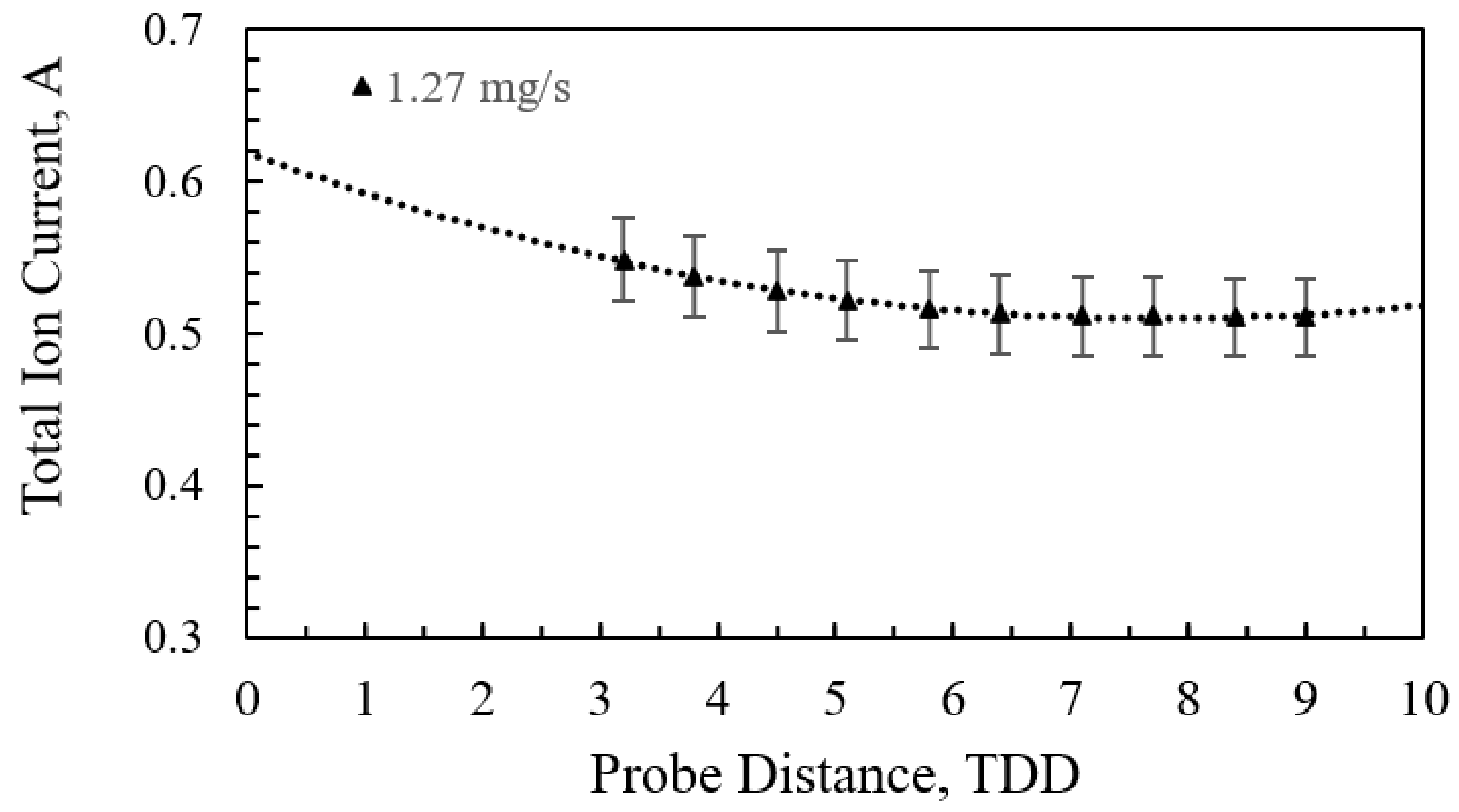
Total ion current as a function of TDD is plotted in Figure 5. Between 4.5 TDD and 9 TDD, where error analysis is valid, total ion beam current decreases by only 0.0175 A, which is within measurement error margins. This shows total ion current as a function of TDD is conserved, further validating the results from Faraday probe measurements. While the analysis methods used for Faraday probe data lose efficacy in the near plume below 4 TDD the trends can still be useful.
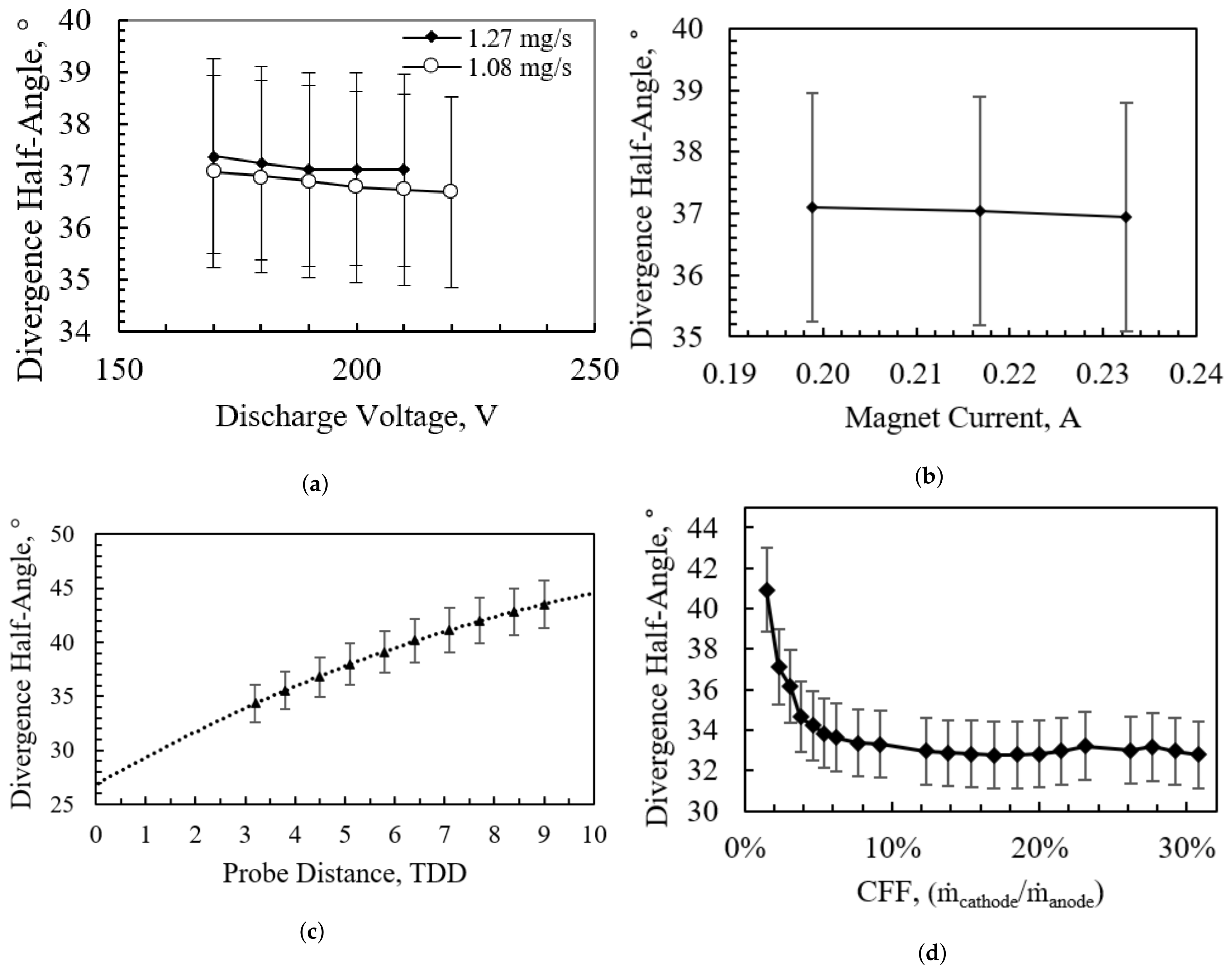
Thruster divergence results are shown in Figure 6. Firstly, divergence angle as a function of discharge voltage (Figure 6a) and as a function of magnet current (Figure 6b at a downstream distance of 4.5 TDD are shown. Next, the divergence angle at the nominal 200-V, 215-W operating condition as a function of probe distance downstream in TDD lengths is shown in Figure 6c. As seen in other thrusters, the plume divergence half-angle increases as collisions between the plume and background neutrals results in a diffusion of the beam into the chamber [12]. Lastly, the divergence angle as a function of CFF at a probe distance downstream of 4 TDD is shown in Figure 6d. As expected with an HET, the divergence angle decreased with increasing discharge voltage. No significant change in plume divergence angle was detected within the measurement error previously indicated over the full range of discharge voltage, anode flow rate, and magnet current tested. An increase in plume divergence angle of about 9 was measured over the full range of downstream distances at the nominal 215-W operating condition. These results show divergence angles that are large when compared to other similarly powered HETs [16,17]. Both of these trends are likely exacerbated by the high operational pressures.
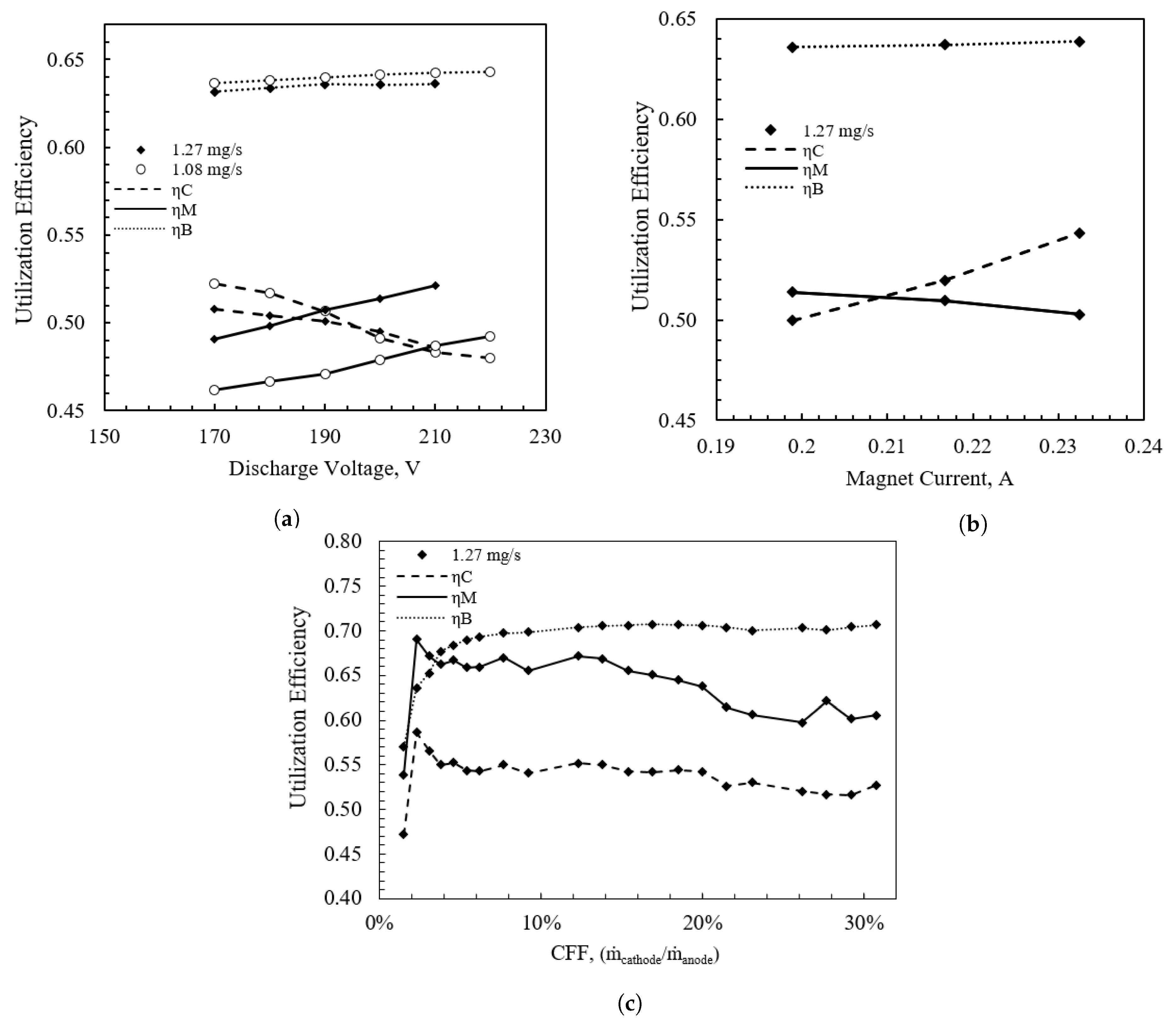
Utilization efficiencies as a function of discharge voltage and magnet current are shown in Figure 7a,b, respectively. Figure 7c shows utilization efficiencies as a function of CFF at the 200-V, 215-W nominal operating condition. There are several behaviors of note in Figure 7a,b:
- Increased anode propellant flow rate resulted in a higher mass utilization efficiency, likely a result of an increase in the ionization fraction of neutrals within the discharge channel.
- Increased discharge voltage positively affected mass utilization efficiency, and negatively affected current utilization efficiency.
- Increased magnetic field strength positively affected current utilization efficiency,
Taken together, thruster utilization efficiencies shown in Figure 7c show quite poor performance at the lowest CFF operating point of 1.5% but stabilize to , , and by a CFF of 7%. As CFF was increased, the beam utilization efficiency increased and became steady at 7%. Conversely, the mass and current utilization efficiencies spiked in the beginning and then decreased as CFF continued to increase. Current and beam utilization efficiencies, remained relatively constant at all CFF >7%, which is reflective of a near constant beam ionization fraction and beam divergence. Mass utilization efficiency, naturally decreased due to the relatively constant ion production rate and increasing cathode flow.
3.2. Discharge Oscillations
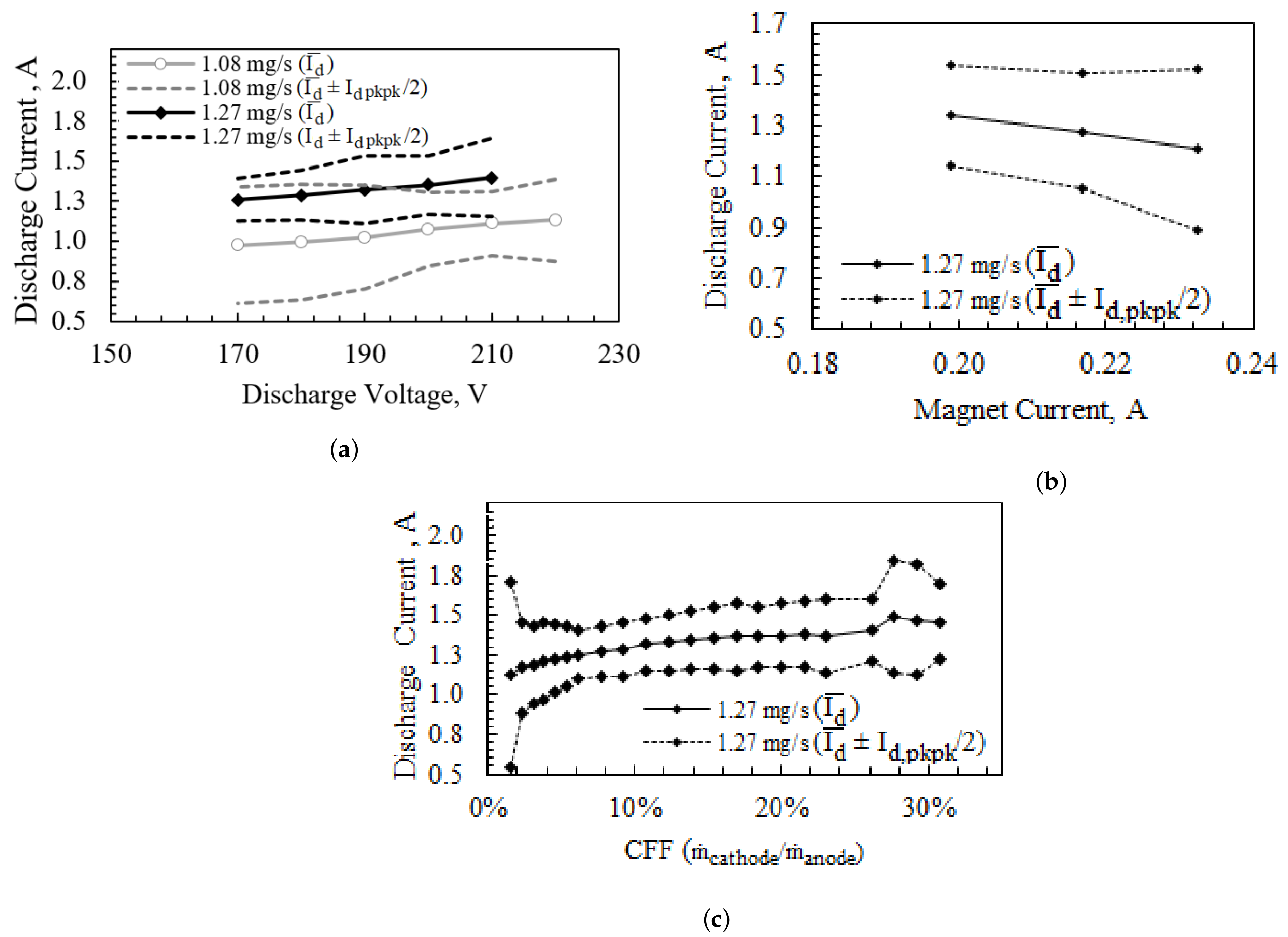
Discharge current measurements were recorded and processed to determine the mean, peak-to-peak, probability distribution, and spectral density. The mean and peak-to-peak discharge current are plotted as a function of the swept parameters in Figure 8. Figure 8a shows that, in general, discharge current amplitude decreased with increasing discharge voltage. At some operating conditions at the 1.27 mg/s flow condition, this trend did not hold. The authors cannot fully explain this inconsistency; however, it is likely the manifestation of a complex relationship between wave dampening and changes in the position and length of the ionization zone within the thruster due to an increase in the number of background neutrals. Peak-to-peak discharge current oscillations increased with increasing magnetic field strength, while the mean discharge current decreased as magnetic field strength increased as shown in Figure 8b. Figure 8c shows the mean and average maximum and minimum of the thruster discharge current as a function of CFF at an anode flow rate of 1.27 mg/s. The amplitude of the discharge current oscillations was lowest at a CFF of 6% and increased sharply at CFFs below 3% and above 26%. This behavior is consistent with results reported in reference [18] wherein large ion instabilities occur at very low cathode flow rates, and turbulent ion acoustic waves drive increased oscillations at higher cathode flow rates.
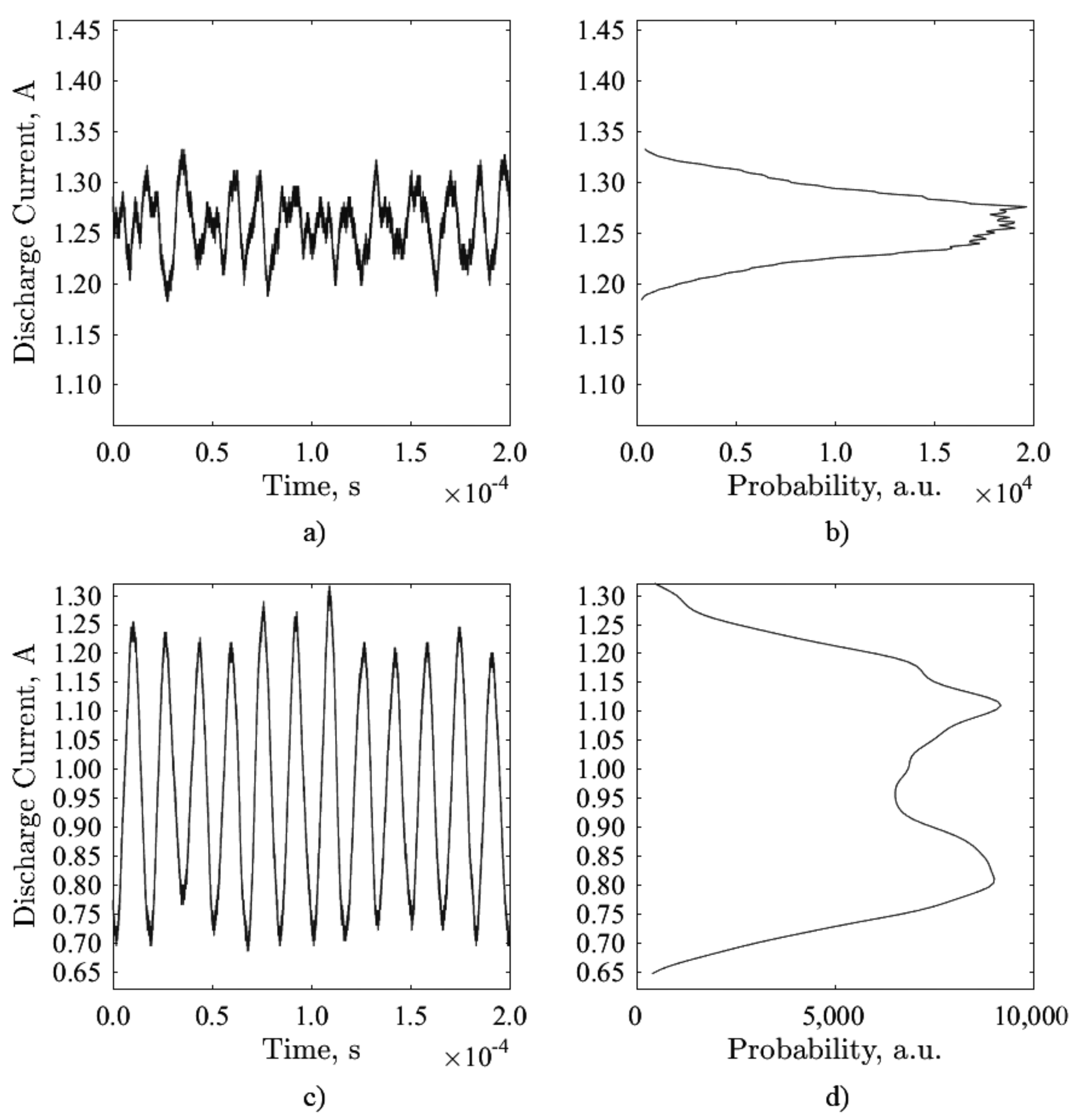
Utilizing a simple histogram function on the discharge current data, a probability distribution function (PDF) was obtained. The oscillatory behavior of the discharge current at nearly every thruster operating condition exhibited what will herein be referred to as a Gaussian-like probability distribution. An example of this behavior is shown in Figure 9a,b where the thruster is operating at a discharge voltage of 170 V and an anode flow rate of 1.27 mg/s. Two operating conditions were found to be exceptions to the Gaussian PDF where the discharge current oscillations behaved sinusoidally resulting in a twin-peak PDF, as shown in Figure 9c,d. The operating conditions that resulted in sinusoidal behavior occurred at discharge voltages of 170 V and 180 V while operating at an anode flow rate of 1.08 mg/s. Notably, the sinusoidal discharge behavior corresponds to the highest amplitude in the discharge current oscillations. Thus, there exists a rapid mode shift from a sinusoidal to a Gaussian distribution at an anode flow rate of 1.08 mg/s between discharge voltages of 180 V and 190 V.
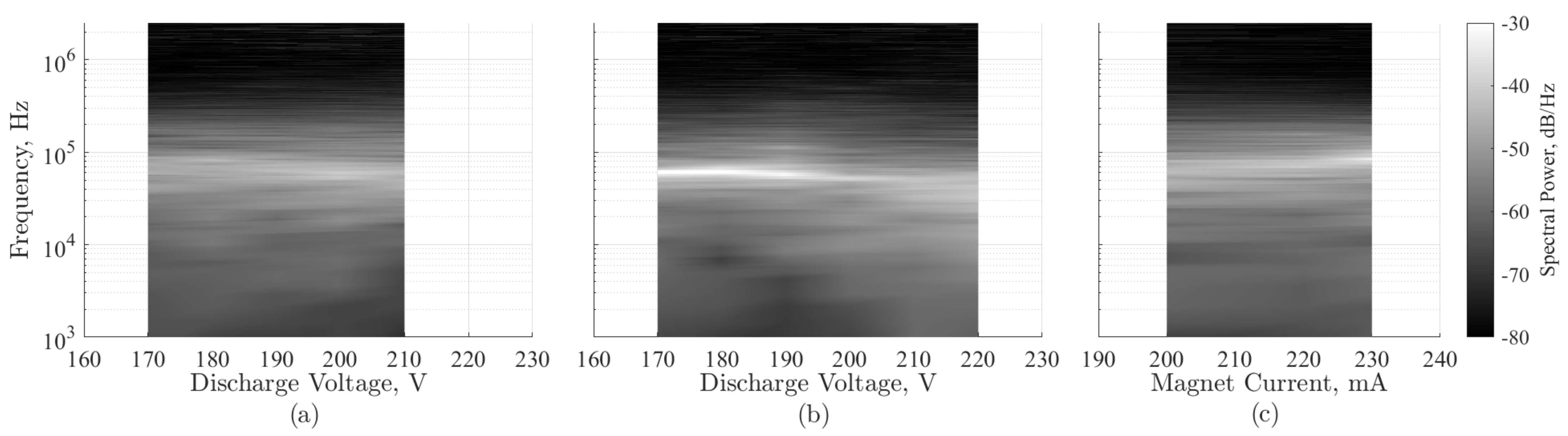
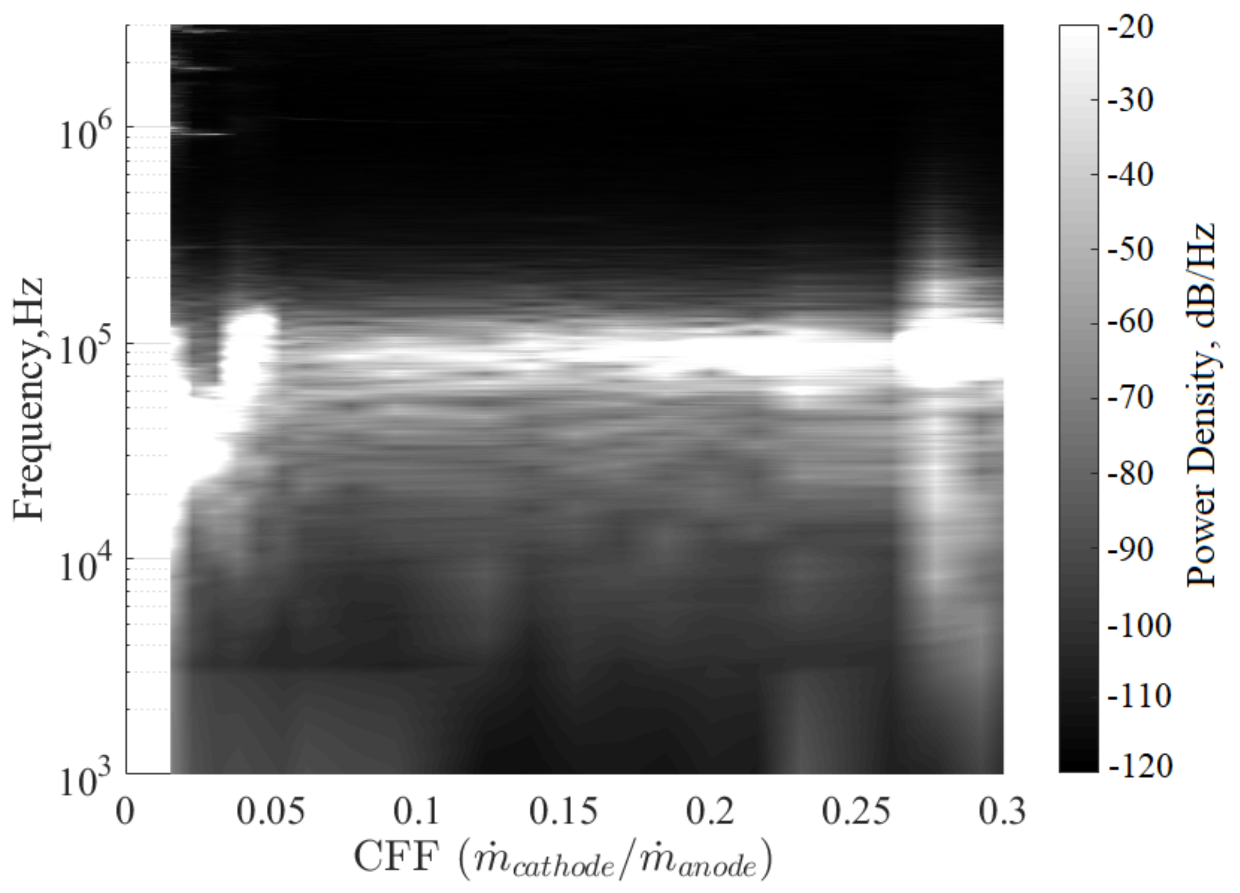
The power spectral density for each of the swept voltages and magnet currents are shown in Figure 10. The characteristic oscillation frequency varied between 60 and 90 kHz for all operating conditions, which was higher than expected based on other similarly sized thrusters [19,20]. As discharge voltage was increased at the high flow condition, Figure 10a, the strongest oscillation frequency remained largely constant at about 60 kHz, and the spectral strength remained broadband throughout the range of discharge voltages swept. As discharge voltage was increased at the low flow condition, Figure 10b, the oscillation frequency, initially a strong sinusoidal 60 kHz behavior, decreased to a Gaussian-like oscillation centered at approximately 40 kHz. While the sinusoidal behavior appears relatively “clean”, there was a greater than normal tendency for the thruster to extinguish under these operating conditions. As magnetic field strength was increased, Figure 10c, the strongest oscillation frequency increased monotonically from about 60 kHz to 85 kHz while also increasing in power. The power spectral density as a function of the CFF is shown in Figure 11. At both the highest and lowest CFF, the discharge exhibited a very broadband oscillation varying from 10 kHZ to 150 kHz. These extremes in the CFF also corresponded to increases in the peak-to-peak discharge current oscillations. Between the extreme limits of the CFF the discharge oscillation frequency remained near 90 kHz and showed a near constant spectral profile as the CFF increased. Moreover, 6% CFF is the most spectrally quiescent over the span of CFF tested.
Throughout the entire study, the discharge current oscillation frequency largely remained between 45 kHz and 90 kHz. This is a surprising result due to the fact that typical breathing mode oscillations occur between 30 kHz and 50 kHz in a similarly sized non-magnetically shielded thruster [21]. This may be indicative of flow non-uniformities that result in either localized high neutral velocity regions or low characteristic oscillation length, . Another possible source of these oscillations could be off-axis cathode oscillation modes coupling to the thruster discharge. Future experiments with high-speed imaging could reveal the source of these oscillations.
The WHT44 was operated for a duration of 10 h during this campaign, resulting in a total WHT44 operation time of 42 h. Testing concluded prematurely after a segment of the discharge channel insulator fractured and exposed the front magnetic pole to plasma in the acceleration region. Future plans include making repairs to the discharge channel and continuing with additional plume diagnostics on the WHT44.
4. Conclusions
The laboratory model, 200-W WHT44 was examined at an array of operating conditions while sweeping discharge voltage, propellant flow rate, magnetic field strength, and CFF. At each operating point, average telemetry, high-speed discharge behavior, and multiple wide angle FP sweeps were performed. Plume divergence, utilization efficiencies, and discharge current oscillations were quantified showing low thruster efficiencies and a higher than expected dominant oscillation frequency. The WHT44 would benefit from design refinement to increase thermal compliance, increase anode flow uniformity, and conventionalize channel geometry. These changes would likely result in increased ionization zone length, decreased thruster discharge oscillation frequency, and increased stability. Moreover, a study performed on the WHT44 in a facility with higher pumping capacity could greatly expand many of the results reported here.
Author Contributions
Conceptualization, M.B. and K.L.; methodology, M.B. and T.K.; software, M.B. and T.K.; validation, M.B. and K.L.; formal analysis, M.B. and T.K.; investigation, M.B., T.K. and R.M.-S.; resources, K.L.; data curation, M.B.; writing—original draft preparation, M.B., T.K. and R.M.-S.; writing—review and editing, K.L.; visualization, M.B. and T.K.; supervision, K.L.; project administration, K.L.; funding acquisition, M.B. and K.L. All authors have read and agreed to the published version of the manuscript.
Funding
The authors would like to thank Western Michigan University’s Office of the Vice President for Research for the undergraduate research excellence award used to purchase of all the materials needed for fabrication of the WHT44. This work was supported by a NASA Space Technology Research Fellowship grant number NNX16AM96H.
Data Availability Statement
Data available upon request. Please email Dr. Kristina Lemmer at [email protected].
Conflicts of Interest
The authors declare no conflict of interest.
References
- Goebel, D.M.; Katz, I. Fundamentals of Electric Propulsion: Ion and Hall Thrusters; John Wiley & Sons, Inc.: Hoboken, NJ, USA, 2008. [Google Scholar] [CrossRef]
- Lev, D.; Myers, R.M.; Lemmer, K.M.; Kolbeck, J.; Keidar, M.; Koizumi, H.; Liang, H.; Yu, D.; Schönherr, T.; Gonzalez Del Amo, J.; et al. The Technological and Commercial Expansion of Electric Propulsion in the Past 24 Years. In Proceedings of the 35th International Electric Propulsion Conference, Atlanta, GA, USA, 8–12 October 2017. [Google Scholar]
- Brophy, J.R. Legacy of the Asteroid Redirect Robotic Mission (ARRM). In Proceedings of the 35th International Electric Propulsion Conference, Atlanta, GA, USA, 8–12 October 2017. [Google Scholar]
- Baird, M.J.; Simmons, N.A.; Lemmer, K.M. Design and Initial Operation of a Small Low-cost Hall Thruster. In Proceedings of the 35th International Electric Propulsion Conference, Atlanta, GA, USA, 8–12 October 2017. [Google Scholar]
- Baird, M.J.; Simmons, N.A.; Lemmer, K.M. Performance characterization of a small low-cost Hall thruster. In Proceedings of the 35th International Electric Propulsion Conference, Atlanta, GA, USA, 8–12 October 2017. [Google Scholar]
- Comsol. Introduction to COMSOL Multiphysics; 2017. [Google Scholar]
- Choueiri, E.Y. Plasma oscillations in Hall thrusters. Phys. Plasmas 2001, 8, 1411–1426. [Google Scholar] [CrossRef] [Green Version]
- Fife, J.M.; Martinez-Sanchez, M.; Szabo, J. A Numerical Study of Low-Frequency Discharge Oscillations in Hall Thrusters. In Proceedings of the 33rd AIAA/SAE/ASEE Joint Propulsion Conference, Seattle, WA, USA, 6–9 July 1997. [Google Scholar] [CrossRef] [Green Version]
- Sekerak, M.J. Plasma Oscillations and Operational Modes in Hall Effect Thrusters. Ph.D. Thesis, University of Michigan, Ann Arbor, MI, USA, 2014. [Google Scholar]
- Boeuf, J.P.; Takahashi, M. New insights into the physics of rotating spokes in partially magnetized e × B plasmas. Phys. Plasmas 2020, 27. [Google Scholar] [CrossRef]
- Mazouffre, S.; Grimaud, L.; Tsikata, S.; Matyash, K.; Schneider, R. Rotating spoke instabilities in a wall-less Hall thruster: Simulations. arXiv 2019, 28, 054002. [Google Scholar]
- Brown, D.L.; Walker, M.L.R.; Szabo, J.; Huang, W.; Foster, J.E. Recommended Practice for Use of Faraday Probes in Electric Propulsion Testing. J. Propuls. Power 2017, 33, 582–613. [Google Scholar] [CrossRef] [Green Version]
- Kerber, T.V.; Baird, M.J.; Mcgee-sinclair, R.F.; Lemmer, K.M. Background Pressure Effects on Plume Properties of a Low-Cost Hall Effect Thruster. In Proceedings of the International Electric Propulsion Conference 2019, Vienna, Austria, 15–20 September 2019; pp. 1–10. [Google Scholar]
- Goebel, D.M.; Jameson, K.K.; Hofer, R.R. Hall Thruster Cathode Flow Impact on Coupling Voltage and Cathode Life. J. Propuls. Power 2012, 28, 355–363. [Google Scholar] [CrossRef]
- Kamhawi, H.; Huang, W.; Haag, T.W.; Shastry, R.; Thomas, R.; Yim, J.T.; Herman, D.A.; Williams, G.; Myers, J.; Hofer, R.R.; et al. Performance and Facility Background Pressure Characterization Tests of NASA’s 12.5-kW Hall Effect Rocket with Magnetic Shielding Thruster NASA’s Space Technology Mission Directorate (STMD) Solar Electric Propulsion. In Proceedings of the 34th International Electric Propulsion Conference, Kobe, Japan, 4–10 July 2015. [Google Scholar]
- Brown, D.L.; Larson, C.W.; Beal, B.E.; Gallimore, A.D. Methodology and Historical Perspective of a Hall Thruster Efficiency Analysis. J. Propuls. Power 2009, 25, 1163–1177. [Google Scholar] [CrossRef]
- Conversano, R.W.; Goebel, D.M.; Hofer, R.R.; Mikellides, I.G.; Wirz, R.E. Performance Analysis of a Low-Power Magnetically Shielded Hall Thruster: Experiments. J. Propuls. Power 2017, 33, 975–983. [Google Scholar] [CrossRef]
- Goebel, D.M.; Jameson, K.K.; Katz, I.; Mikellides, I.G. Potential Fluctuations and Energetic Ion Production in Hollow Cathode Discharges. Phys. Plasmas 2007, 14, 103508. [Google Scholar] [CrossRef]
- Conversano, R.W.; Lobbia, R.B.; Tilley, K.C.; Goebel, D.M.; Reilly, S.W.; Mikellides, I.G.; Hofer, R.R. Development and Initial Performance Testing of a Low-Power Magnetically Shielded Hall Thruster with an Internally-Mounted Hollow Cathode. In Proceedings of the 35th International Electric Propulsion Conference, Atlanta, GA, USA, 8–12 October 2017. [Google Scholar]
- Grimaud, L.; Mazouffre, S. Conducting wall Hall thrusters in magnetic shielding and standard configurations. J. Appl. Phys. 2017, 122. [Google Scholar] [CrossRef]
- Brown, D.L.; Lobbia, R.B. Characterization of Hall Thruster Mode Transitions and Facility Interactions. In Proceedings of the 62nd JANNAF Propulsion Meeting, Nashville, TN, USA, 7–11 December 2015. [Google Scholar]
Figure 1.
Langmuir probe I-V traces for 44-mm-diameter Western Hall Thruster (WHT44) at 200 W and several plume locations.
Figure 1.
Langmuir probe I-V traces for 44-mm-diameter Western Hall Thruster (WHT44) at 200 W and several plume locations.

Figure 2.
Experimental setup.

Figure 3.
Photograph of the (a) WHT44 post-test and (b) the WHT44 operating at the nominal operating point.
Figure 3.
Photograph of the (a) WHT44 post-test and (b) the WHT44 operating at the nominal operating point.

Figure 4.
Sample Faraday probe current density measurements at 10 different thruster diameters downstream (TDD) distances plotted together for the nominal 200-V, 215-W operating condition.
Figure 4.
Sample Faraday probe current density measurements at 10 different thruster diameters downstream (TDD) distances plotted together for the nominal 200-V, 215-W operating condition.

Figure 5.
Total ion beam current as a function of TDD at the nominal 200-V, 215-W operating condition.
Figure 5.
Total ion beam current as a function of TDD at the nominal 200-V, 215-W operating condition.

Figure 6.
Divergence angle as a function of (a) discharge voltage, (b) magnet current at 4.5 TDD, (c) probe distance downstream at nominal operating conditions, and (d) of cathode flow fraction (CFF) at 4 TDD.
Figure 6.
Divergence angle as a function of (a) discharge voltage, (b) magnet current at 4.5 TDD, (c) probe distance downstream at nominal operating conditions, and (d) of cathode flow fraction (CFF) at 4 TDD.

Figure 7.
Current utilization, mass utilization, and beam utilization efficiencies at a probe distance 4.5 TDD as a function of (a) discharge voltage, (b) magnet current, (c) CFF at 4 TDD.
Figure 7.
Current utilization, mass utilization, and beam utilization efficiencies at a probe distance 4.5 TDD as a function of (a) discharge voltage, (b) magnet current, (c) CFF at 4 TDD.

Figure 8.
The mean and peak-to-peak discharge current as a function of (a) discharge voltage, (b) magnet current, and (c) cathode flow fraction.
Figure 8.
The mean and peak-to-peak discharge current as a function of (a) discharge voltage, (b) magnet current, and (c) cathode flow fraction.

Figure 9.
Discharge current as a function of time at 170 V for mass flow rates of (a) 1.27 mg/s, and (c) 1.08 mg/s. Histograms of discharge current at (b) 1.27 mg/s setting, and (d) 1.08 mg/s setting.
Figure 9.
Discharge current as a function of time at 170 V for mass flow rates of (a) 1.27 mg/s, and (c) 1.08 mg/s. Histograms of discharge current at (b) 1.27 mg/s setting, and (d) 1.08 mg/s setting.

Figure 10.
Thruster discharge power spectral behavior for a CFF of 20.7% and: (a) 1.27 mg/s and 200 mA, (b) 1.08 mg/s and 200 mA, and (c) 1.27 mg/s at a 200 V discharge.
Figure 10.
Thruster discharge power spectral behavior for a CFF of 20.7% and: (a) 1.27 mg/s and 200 mA, (b) 1.08 mg/s and 200 mA, and (c) 1.27 mg/s at a 200 V discharge.

Figure 11.
Thruster discharge power spectral behavior for the 170 V discharge, 1.27 mg/s, and 200 mA condition as a function of CFF.
Figure 11.
Thruster discharge power spectral behavior for the 170 V discharge, 1.27 mg/s, and 200 mA condition as a function of CFF.


Table 1.
Summary of parameterization setpoints with discharge powers highlighted. The 215 W operating condition (in bold) is designated the nominal operating point.
Table 1.
Summary of parameterization setpoints with discharge powers highlighted. The 215 W operating condition (in bold) is designated the nominal operating point.
| Discharge Power, W | |||||||||||||||||||||||
|---|---|---|---|---|---|---|---|---|---|---|---|---|---|---|---|---|---|---|---|---|---|---|---|
| Discharge Voltage, V | |||||||||||||||||||||||
| Anode flow | (Im = 200 mA; CFF = 20.7%) | ||||||||||||||||||||||
| Rate, mg/s | 170 | 180 | 190 | 200 | 220 | ||||||||||||||||||
| 1.27 | 214 | 232 | 251 | 270 | 293 | - | |||||||||||||||||
| 1.08 | 166 | 179 | 195 | 215 | 233 | 249 | |||||||||||||||||
| Magnet Current, mA (Vd = 200 V; CFF = 20.7%) | |||||||||||||||||||||||
| 200 | 217 | 233 | |||||||||||||||||||||
| 1.27 | 268 | 255 | 241 | ||||||||||||||||||||
| Cathode Flow Fraction,% (Vd = 170 V; Im = 200 mA) | |||||||||||||||||||||||
| 2 | 2 | 2 | 3 | 4 | 5 | 5 | 6 | 8 | 9 | 11 | 12 | 14 | 15 | 17 | 19 | 20 | 22 | 23 | 26 | 28 | 29 | 31 | |
| 1.27 | 192 | 191 | 198 | 201 | 205 | 207 | 210 | 212 | 215 | 217 | 222 | 224 | 227 | 229 | 231 | 230 | 232 | 233 | 231 | 238 | 252 | 248 | 246 |
Publisher’s Note: MDPI stays neutral with regard to jurisdictional claims in published maps and institutional affiliations. |
© 2021 by the authors. Licensee MDPI, Basel, Switzerland. This article is an open access article distributed under the terms and conditions of the Creative Commons Attribution (CC BY) license (http://creativecommons.org/licenses/by/4.0/).
Share and Cite
MDPI and ACS Style
Baird, M.; Kerber, T.; McGee-Sinclair, R.; Lemmer, K. Plume Divergence and Discharge Oscillations of an Accessible Low-Power Hall Effect Thruster. Appl. Sci. 2021, 11, 1973. https://0-doi-org.brum.beds.ac.uk/10.3390/app11041973
AMA Style
Baird M, Kerber T, McGee-Sinclair R, Lemmer K. Plume Divergence and Discharge Oscillations of an Accessible Low-Power Hall Effect Thruster. Applied Sciences. 2021; 11(4):1973. https://0-doi-org.brum.beds.ac.uk/10.3390/app11041973
Chicago/Turabian StyleBaird, Matthew, Thomas Kerber, Ron McGee-Sinclair, and Kristina Lemmer. 2021. "Plume Divergence and Discharge Oscillations of an Accessible Low-Power Hall Effect Thruster" Applied Sciences 11, no. 4: 1973. https://0-doi-org.brum.beds.ac.uk/10.3390/app11041973
Note that from the first issue of 2016, this journal uses article numbers instead of page numbers. See further details here.