Article

Integrated Design of a Morphing Winglet for Active Load Control and Alleviation of Turboprop Regional Aircraft

1
Adaptive Structures Technologies, The Italian Aerospace Research Centre, CIRA, Via Maiorise, 81043 Capua, Italy
2
Multidisciplinary Design and Analysis, The Italian Aerospace Research Centre, CIRA, Via Maiorise, 81043 Capua, Italy
3
Aerodynamics Aeroelasticity and Acoustics Department, The French Aerospace Lab, ONERA, 92190 Meudon, France
4
Department of Aerospace Science and Technology, Politecnico di Milano, Via La Masa 34, 20156 Milano, Italy
5
Department of Industrial Engineering—Aerospace Division, University of Naples “Federico II”, Via Claudio 21, 80125 Napoli, Italy
6
Adaptive Structures Division, The Italian Aerospace Research Centre, CIRA, Via Maiorise, 81043 Capua, Italy
*
Author to whom correspondence should be addressed.
Submission received: 10 February 2021 / Revised: 28 February 2021 / Accepted: 3 March 2021 / Published: 9 March 2021
(This article belongs to the Special Issue Smart Aircraft Morphing Technologies)

Abstract

:
Aircraft winglets are well-established devices that improve aircraft fuel efficiency by enabling a higher lift over drag ratios and lower induced drag. Retrofitting winglets to existing aircraft also increases aircraft payload/range by the same order of the fuel burn savings, although the additional loads and moments imparted to the wing may impact structural interfaces, adding more weight to the wing. Winglet installation on aircraft wing influences numerous design parameters and requires a proper balance between aerodynamics and weight efficiency. Advanced dynamic aeroelastic analyses of the wing/winglet structure are also crucial for this assessment. Within the scope of the Clean Sky 2 REG IADP Airgreen 2 project, targeting novel technologies for next-generation regional aircraft, this paper deals with the integrated design of a full-scale morphing winglet for the purpose of improving aircraft aerodynamic efficiency in off-design flight conditions, lowering wing-bending moments due to maneuvers and increasing aircraft flight stability through morphing technology. A fault-tolerant morphing winglet architecture, based on two independent and asynchronous control surfaces with variable camber and differential settings, is presented. The system is designed to face different flight situations by a proper action on the movable control tabs. The potential for reducing wing and winglet loads by means of the winglet control surfaces is numerically assessed, along with the expected aerodynamic performance and the actuation systems’ integration in the winglet surface geometry. Such a device was designed by CIRA for regional aircraft installation, whereas the aerodynamic benefits and performance were estimated by ONERA on the natural laminar flow wing. An active load controller was developed by PoliMI and UniNA performed aeroelastic trade-offs and flutter calculations due to the coupling of winglet movable harmonics and aircraft wing bending and torsion.

1. Introduction

Morphing systems have been entered into aircraft design since the very first years of modern aviation [1,2]. Wright’s Flyer [3] or the first concept of aircraft [4], had flexible wings to accomplish the different needs during flight (maneuver, climbing, dive, take-off, landing, etc.). However, the sudden operational speed increase, and the correlated load level rise, moved attention towards more rigid structural elements. Off-cruise operation was assigned to movable devices that were conveniently stowed during flight (flaps, ailerons, etc.). In spite of this, it was well-known that a continuous airfoil variation could lead to fantastic advantages in terms of performance, rather than having segmented pieces that could suitably expand the wing chord, or modify the associated camber. Studies, therefore, continued, until the exceptional flight campaign carried out on the F111 in the 1980s and fully reported some years later, [5]. This is relevant, as the tested architecture on that evolved fighter was not dissimilar to Holle’s patent, dated some 60 years prior! Neither were the architectures presented by Hilbig and Koerner in the same period that dissimilar, as shown in a study sponsored by the newborn Airbus (Messerchmitt–Bolkov–Blohm division) and devoted to civil aircraft [6]. A new wave was started with the introduction of smart materials in the 1990s. The major product of this attention was the massive project “Adaptive Wing”, sponsored by DARPA and carried out by Northrop–Grumman, [7]. This effort may be acknowledged as the start of a new philosophy for aircraft adaptive systems. A major result derived from that experience was that the technologists and scientists realized that morphing architectures could be realized by the use of commercial actuators and other components. It was discovered that what had been searched for, over almost 100 years since the start of modern aviation, was a new design approach. In the subsequent 20 years, two key results may be mentioned. In the USA, a joint project involving NASA, AFRL, Gulfstream, and Flexsys flew a medium-size aircraft with a compliant flap [8]. In Europe, the SARISTU project, led by Airbus, tested a morphing wing system, including adaptive leading and trailing edges and an adaptive winglet, in a wind tunnel [9]. The full-scale CFRP adaptive winglet device was equipped with a morphing skin covering the region between the fixed part and an EMA-actuated tab attached to the winglet’s rear spar by a fail-safe connection (five single hinges) [10]. A further morphing winglet based on a chiral-type internal structure was designed in the framework of the CLAReT project to allow optimal cant angle and twist throughout the flight envelope whilst also providing improved passive gust LCA [11]. In [12], several morphing winglet concepts aiming to improve load control and wing aeroelastic response were investigated.
All these studies and previous experience showed the essential points that an adaptive structure devoted to morphing should accomplish, and, implicitly, what the technology should focus on in order to arrive at a service product, including, among others, the ability to bear operational loads while preserving inner shape variation properties, the possibility of keeping the added number of parts to a minimum so to avoid unnecessary safety issues, aerodynamic and aeroelastic compliance in attaining regular variated shapes and dynamic behavior. These items have been addressed within ongoing studies with Airgreen 2 [13], a Clean Sky 2 (CS2) project aiming to realize models that are forecast to undergo both large wind tunnel and flight test campaigns in 2022–2023. High level system performance requirements and demonstration flight test campaign are both developed under responsibility of Leonardo S.p.A. (Aircraft Division). An advanced high-lift system based on the combined use of a morphing droop nose and a morphing flap is investigated in [14] for integration in a twin-prop regional aircraft equipped with a natural laminar flow wing. Details of the NLF wing design and related performance are discussed in [15]. Two further morphing devices, i.e., a morphing winglet and a morphing wing tip, are being developed within that CS2 project to enhance off-design performance and provide this regional aircraft with load control and alleviation capabilities. In detail, the former incorporates a dedicated actuation mechanism driven by linear electromechanical actuators to adaptively control two independent morphing surfaces of the winglet [16]. The main problems and challenges of such a complex actuation system are discussed in [17], along with the simplified FE modelling approach developed at the preliminary design stages. The related impact on the aeroelastic stability of the aircraft equipped with morphing winglets [18] and adaptive flap tabs [19] was addressed by assuming potential failure scenarios, previously identified through dedicated fault and hazard assessments [20]. Starting from those achievements, this paper intends to focus on the whole design process of the adaptive winglet, and how the abovementioned issues have been faced and successfully solved. Indeed, as well as giving the achieved results, demonstrating a sustained actual flight with those novel structural systems, the aim of the study is to describe the entire design process, ranging from both low-fidelity and high-fidelity aerodynamic simulations and predicting the achieved performance of the winglet, to active load controller design and alleviation performance simulations, aeroelastic trade-off assessments and structural layout design and verification. As aforementioned, in fact, morphing systems should be effectively looked at as a new way to interpret the aircraft system design, overcoming the many trappings that have been formed over almost one century of aircraft engineering. Such an approach promises to be an established base for future developments in the field.

2. Regional Aircraft AG2-Natural Laminar Flow Wing

2.1. Reference Aircraft

The reference aircraft considered in this work is the one designed by Leonardo Company in the framework of the Clean Sky Green Regional Aircraft program. Such a regional aircraft is a 90 passenger turboprop aircraft, referred to as TP90 (Figure 1) throughout this article. In the course of the Clean Sky 2 AG2 project, the TP90 A/C wing shape was redesigned by Onera in order to have extended natural laminar flow (NLF) abilities at cruise. The design considered multi-point optimizations of the airfoils for cruise, climb and low-speed flow conditions (see [14,15] for details about the NLF design). The resulting aircraft configuration is then referred to as AG2-NLF.

2.2. Numerical Methods Used for Aerodynamic Performance Evaluation

For the evaluation of the aerodynamic aircraft performances, the elsA CFD software [22] (ONERA-Airbus-Safran property) was used. This code solves the compressible three-dimensional RANS equations by using a cell-centered finite-volume spatial discretization on structured multi-block meshes.
For the spatial scheme, the one proposed by Jameson [23], is used for the conservative variables. A fourth-order linear dissipation κ4 is generally used, with added second-order dissipation terms κ2 for the treatment of flow discontinuities. The turbulence model used is the one-equation Spalart–Allmaras model with the QCR modification [24]. Multi-grid computations have been used for convergence acceleration.
An adaptation of the computational grid is necessary for the evaluation of the morphed winglet shapes. Among the different possible methods, the one used in in the SARISTU project [25] and described in [26], has been retained. This first considers a deformation of the surface grid of the wing, which then propagates into the 3D volumic grid002E.
Finally, it is necessary to compute the location of the transition line on the wing for an accurate estimation of the performance of the NLF wing. The elsA software has the ability to compute laminar flow regions and to determine the transition location by using the AHD compressible criterion for Tollmien–Schlichting instabilities and the C1 criterion for crossflow instabilities within the iterative convergence process of the RANS computation, as described in [27].

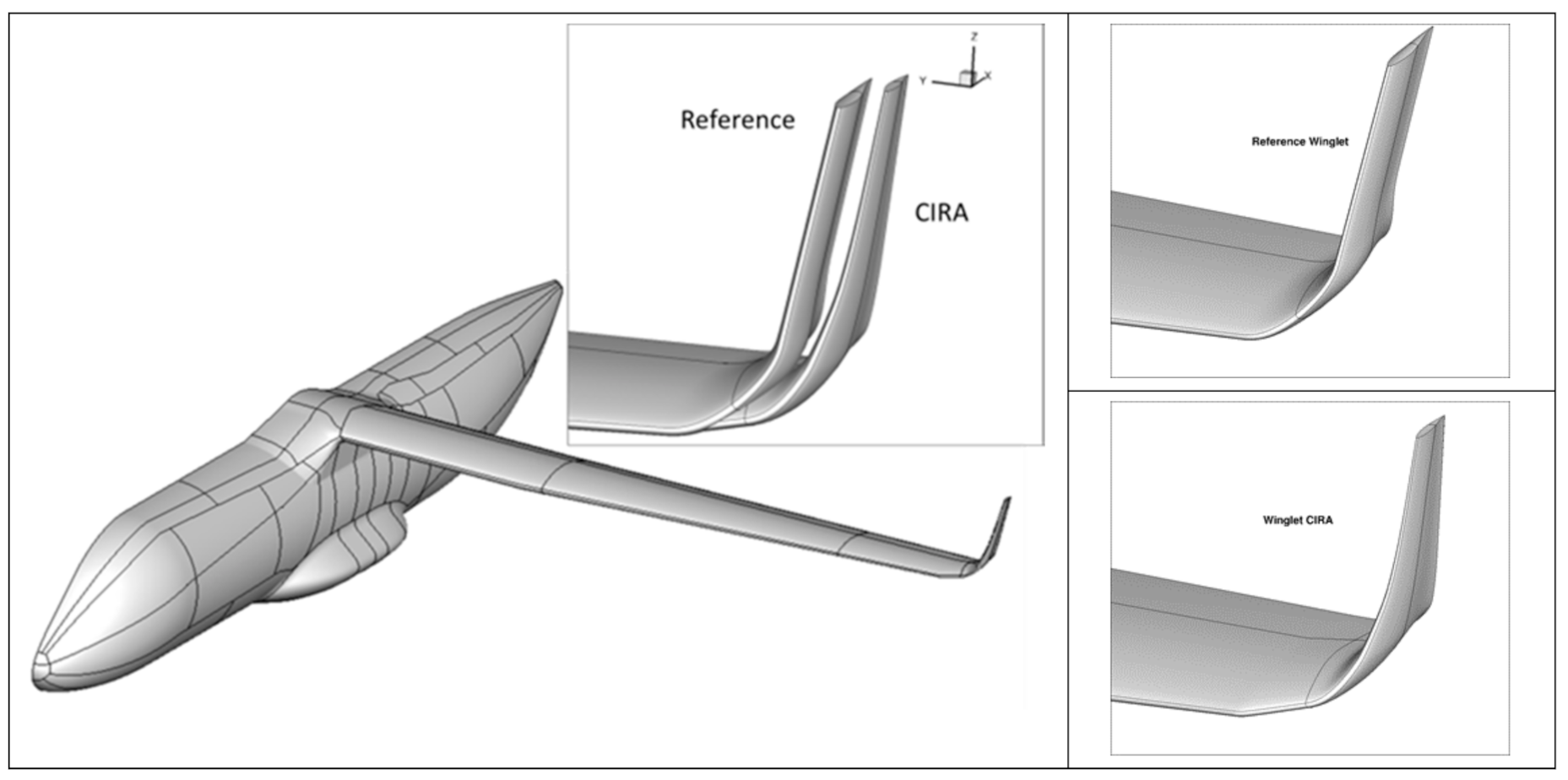
2.3. AG2-NLF Wing Equipped with Reference Winglets

In a second design step, the AG2-NLF wing was equipped with reference winglets, designed by the Leonardo Company, and new Karman fairings. The different design integrations made on the reference TP90 aircraft in order to create the reference AG2-NLF aircraft did not significantly affect the NLF characteristics found on the wing-alone computations. In a general overview, a laminar flow extension on about 50% of both the upper and lower surfaces is found on a large range of incidence, which satisfies the aerodynamic design constraints. On the upper surface (Figure 2), NLF flow is lost for α higher than 6.5° roughly (CL higher than 1.0). On the lower surface (Figure 3), a turbulent flow behavior is found at the wing tip at α = 0°, but the laminar flow extends to nearly mid-chord for the other wing sections.
Figure 4 shows the computed aerodynamic performance of this reference aircraft wing, including winglets, at cruise conditions, for both turbulent and NLF flow conditions. In terms of performance, the NLF technology allows a global drag reduction of about 40d.c. at the flight CL (0.50), or an improvement of about 41d.c. However, note that the computations do not consider the nacelle and the propeller. Therefore, these values have to be considered as the upper limit of the performance improvement, which will be observed on the total aircraft configuration.

2.4. A/C Aero-Structural Model

2.4.1. Structural Model

The structural model of the complete aircraft was developed using NeoCASS [28]. Such a first guess included the preliminary mass and stiffness distribution on the basis of a simplified structural description of the aircraft, where the main structural components were modelled using beam elements. This model provides a useful starting point for the preliminary evaluation of the main aeroelastic properties of the aircraft and the effect of the morphing winglet on both the aircraft stability and aerodynamic loads. In addition, it enables the initial design of an active load alleviation system based on the availability of the morphing mobile surfaces on the winglet.
The structural sizing module of NeoCASS generates a model where the main structural components are represented by beam element, as shown in Figure 5. The model included both the baseline aircraft and the winglets; the winglet’s mass and stiffness were included in the model to properly assess the related impact on airframe loads and aeroelastic stability, and no structural model was considered for the control surfaces, which were represented only through their estimated mass properties and as aerodynamic elements.
The structural mass and stiffness matrices are assembled by the aeroelastic analysis module of NeoCASS, which employs a Finite Volume formulation for the beam elements [29]. A modal analysis is then performed on the structural matrices to obtain a set of natural modes able to represent the dynamic response of the aircraft in free flight, such as
M q ¨ + K q = f a ,
where q is the set of natural modes and M and K are, respectively, the associated modal mass and stiffness matrices. The vector of generalized external forces, f a , contains the unsteady aerodynamic forces that will be discussed in the following paragraph.

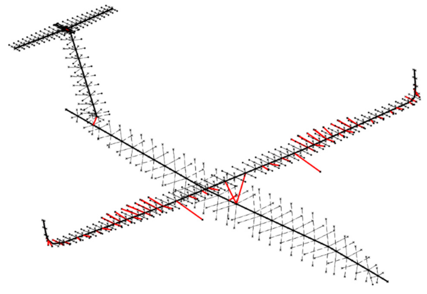
2.4.2. Aerodynamic Model

To perform aeroelastic analyses it is also necessary to have a description of linear unsteady aerodynamic forces coupled with the structural response. This is obtained by the definition of an aerodynamic mesh, shown in Figure 6, which is used by the Doublet Lattice Method (DLM) [30] implemented in NeoCASS to obtain a set of frequency-dependent matrices. These matrices represent the generalized aerodynamic forces associated with the computed set of structural natural modes.
The aerodynamic model also includes the definition of the control surfaces, these include both the main control surfaces (ailerons, rudder and elevator) and the two portions of the control surface included in the winglet, shown in Figure 7.
The final formulation of the generalized aerodynamic forces is
f a = q   H a m   j ω q + q   H a g   j ω v g + q H a δ j ω δ c ,
where q is the dynamic pressure and v g is the gust velocity, defined as an additional forcing input for the system, along with the commanded deflection of the control surfaces δ c   . The aerodynamic matrices H a m   j ω , H a g   j ω and H a δ j ω are tabulated for discrete values of the frequency ω and can only be directly used in frequency domain analyses.

3. Aerodynamic Design and Performance of the Morphing Winglet

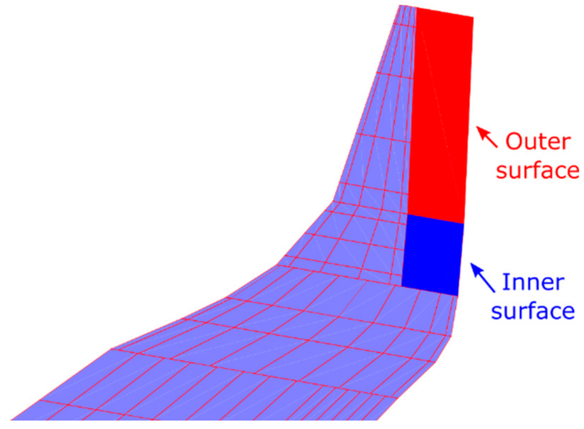
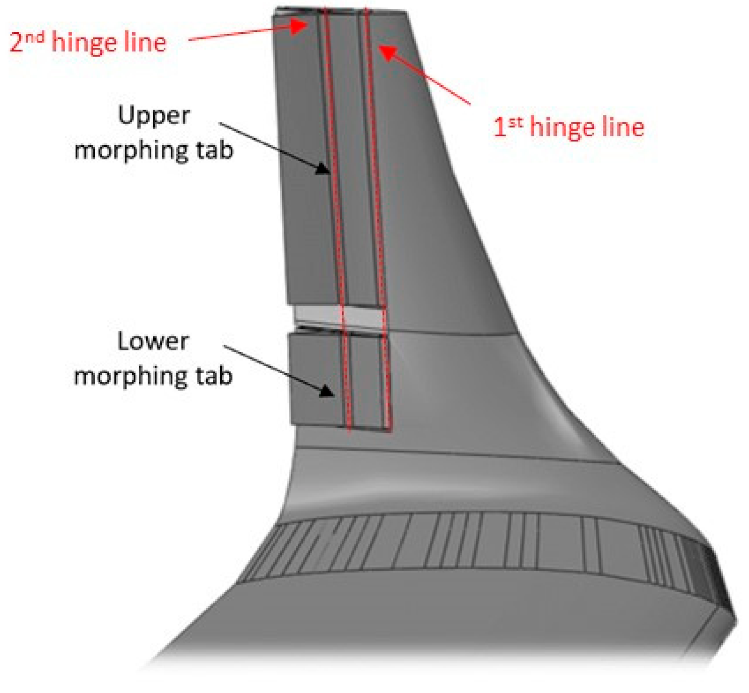
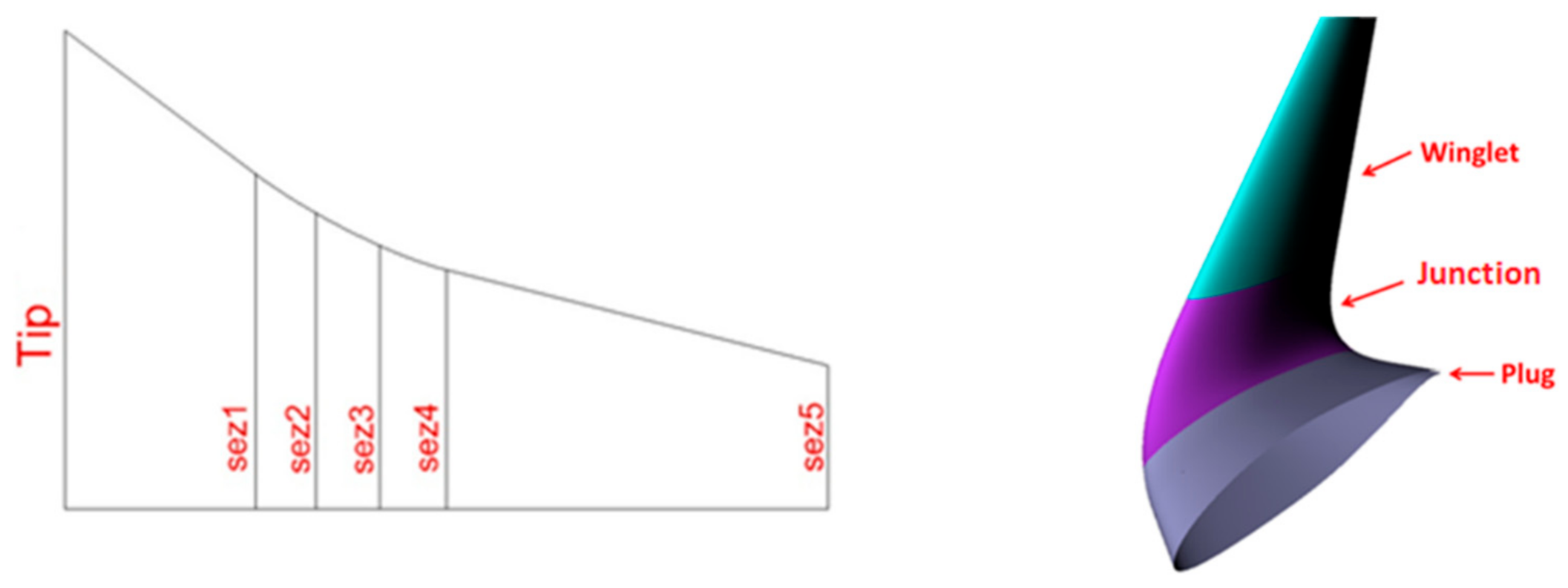
3.1. Morphing Winglet Concept

Besides significant aerodynamic benefits allowing reduced fuel consumption, morphing winglets have attracted growing attention in aviation because of their adaptive ability to lower wing-bending moments and increase aircraft flight stability in response to changing flight conditions. Several morphing winglet concepts have been patented [31,32], or are being developed [33,34], to alleviate gust loads and control the wing lift distribution over the wingspan through adaptive geometries. For the purpose of this research, the morphing winglet developed by CIRA is investigated for regional aircraft application. It consists of two “finger-like” mechanisms, shown in Figure 8, controlling the movement of movable surfaces (namely, upper and lower tabs), whose deflections are driven by dedicated electromechanical actuators [17]. By independently rotating the upper and lower surfaces, such an adaptive device is capable to both increase off-design aerodynamic efficiency by reducing induced drag and alleviate gust and maneuver loads by moving the surfaces, either synchronously or independently, to different angles. However, compared to more conventional plain flaps located at the trailing edge of the airfoils, the rear portion of the two morphing surfaces rotates upwards and downwards on two hinge lines of the finger-like mechanism. Such a morphing mechanism was already successfully validated on both full-scale morphing wing trailing edge [35,36,37] and aileron demonstrators [38,39,40].

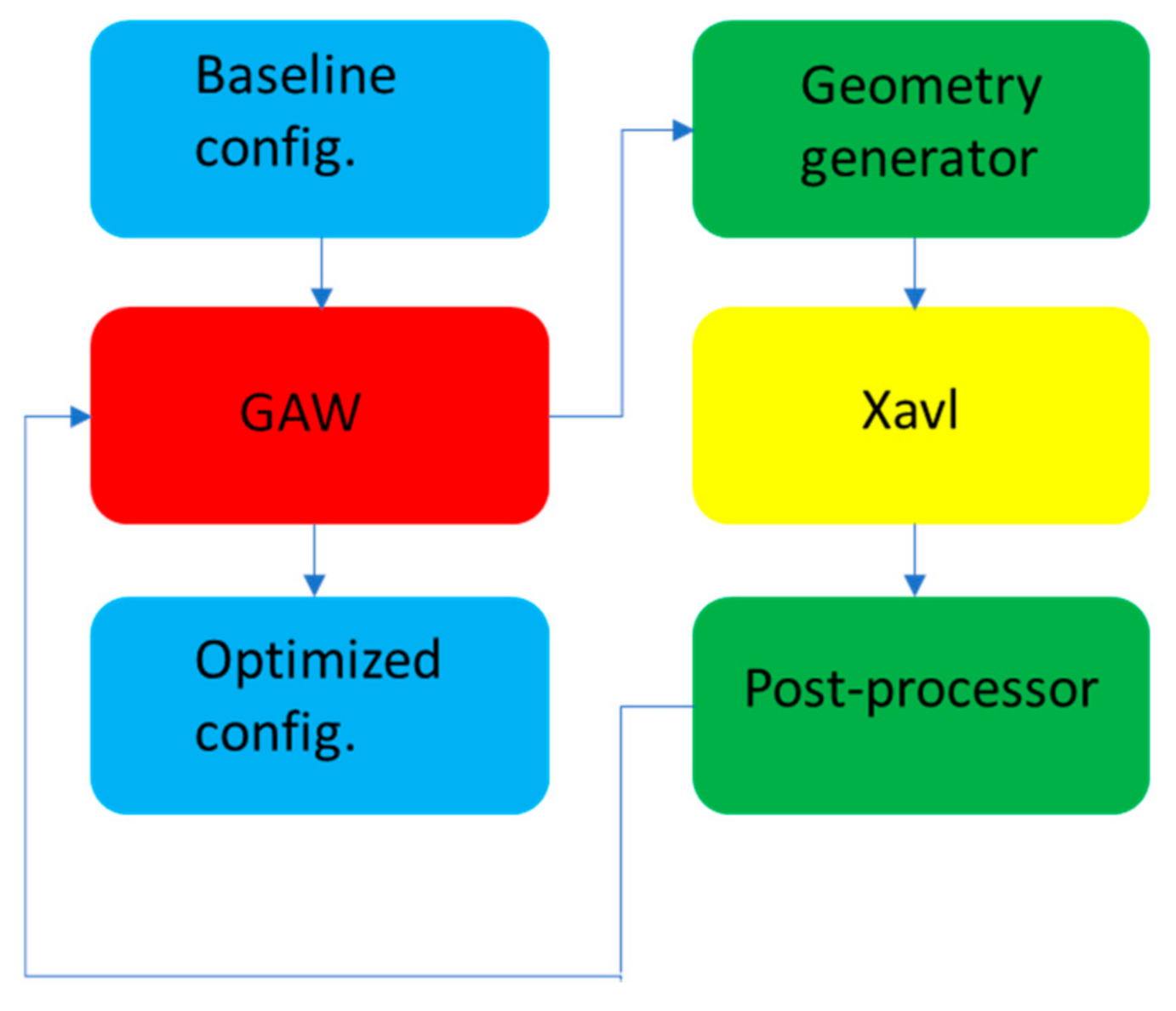
3.2. Low-Fidelity Simulations

A low-order homebuilt solver (CIRA property) was used to optimize the winglet aerodynamic shape and to carry out the preliminary morphing winglet performance assessment. The Xavl code [41] is a 2.5D methodology which couples an inviscid 3D VLM solution carried out by the AVL public domain solver developed at MIT [42] with viscous 2D databases computed in a series of defined wingspanwise sections. The coupling between 3D inviscid solution and 2D viscous data is obtained by using the equivalent mean-line approach. The use of this low-fidelity code makes it possible to execute a full aerodynamic optimization with acceptable computational cost. The aerodynamic design was accomplished using the optimization chain described in Figure 9. The chain consists of an optimization tool (GAW), based on the Pareto dominance [43,44], the aerodynamic solver Xavl and a post-processor.
Both the planform and the airfoil shapes of the winglet were concurrently optimized. The former aimed to maximize the aerodynamic efficiency in three different design points, including cruise, climb and climb, in one-engine-out conditions. The morphing airfoils’ shape optimization had the additional goal of reducing the bending root moment in the most severe loading conditions. The winglet geometry was parametrized on a five-design section, shown in Figure 10. In each station, the GAW optimization tool is allowed to modify the sweep angle, the twist angle, the chord extension and the cant angle. The overall winglet height was not a direct design variable, but the GAW tool could modify the spanwise distance between each of the five-design section stations.

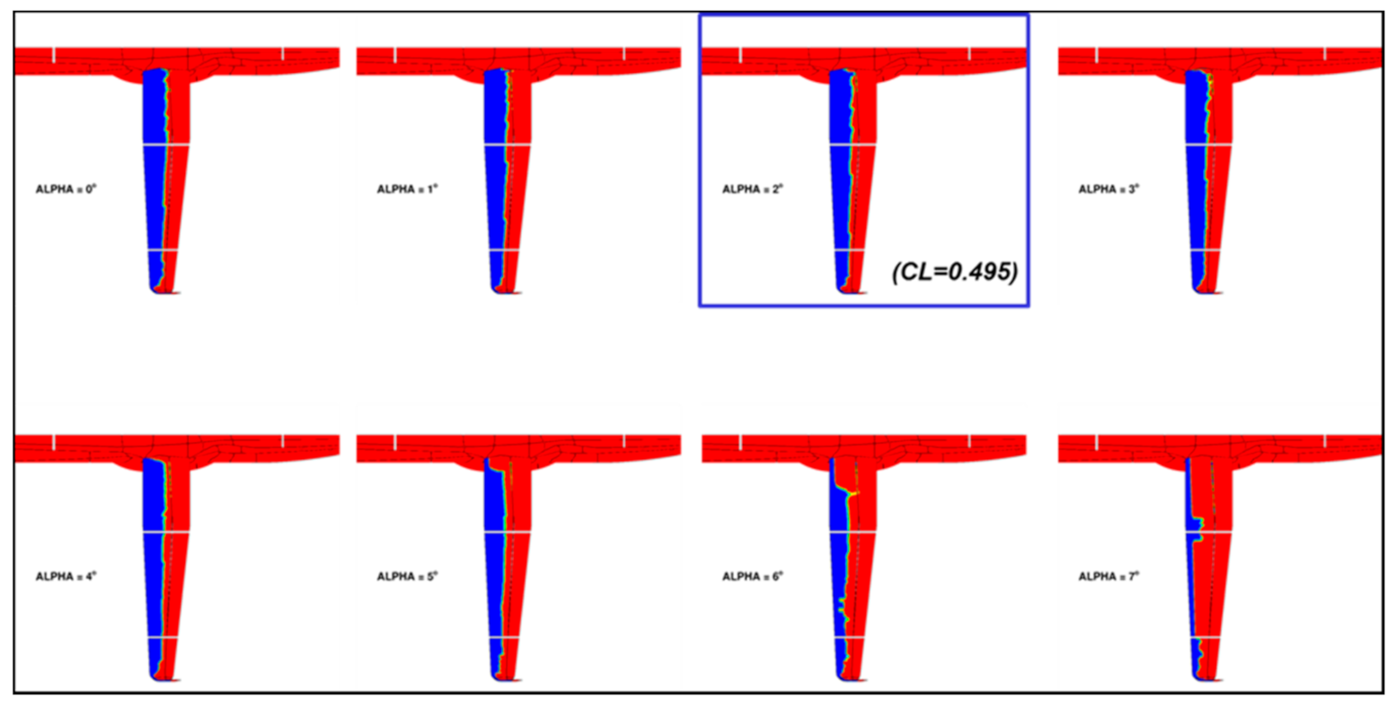
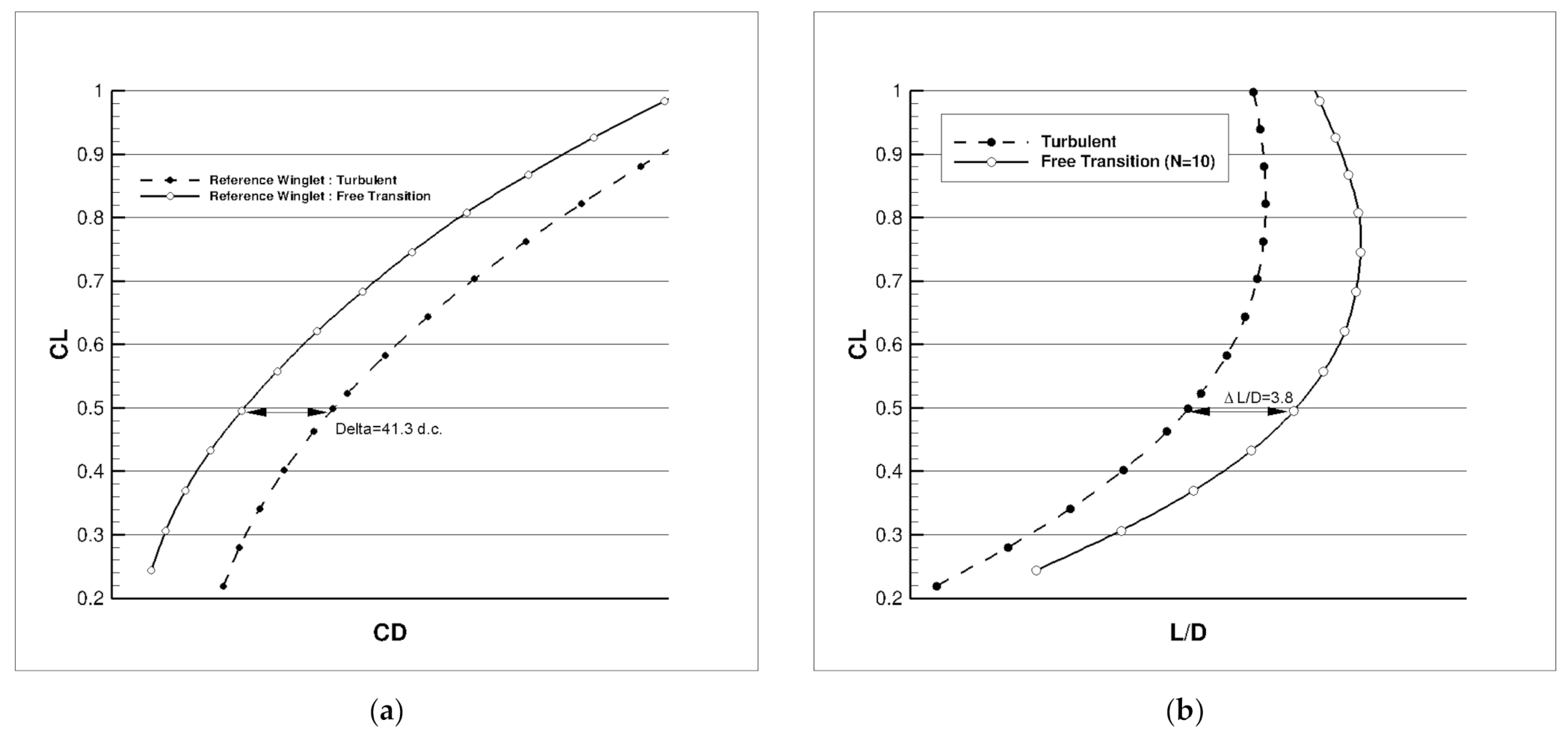
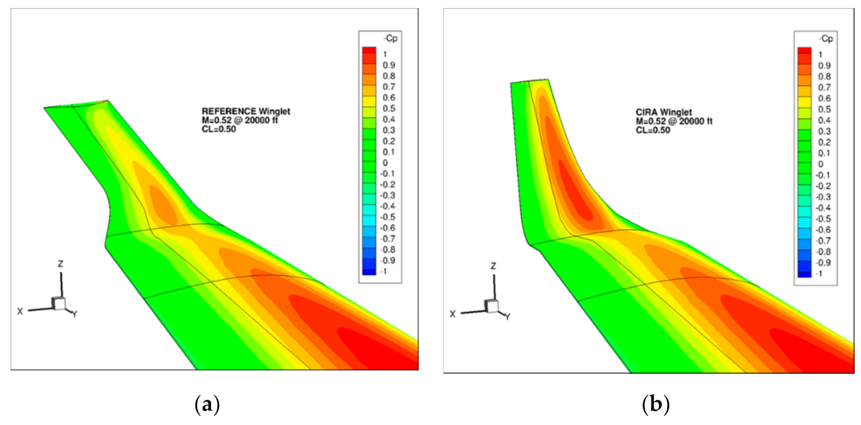
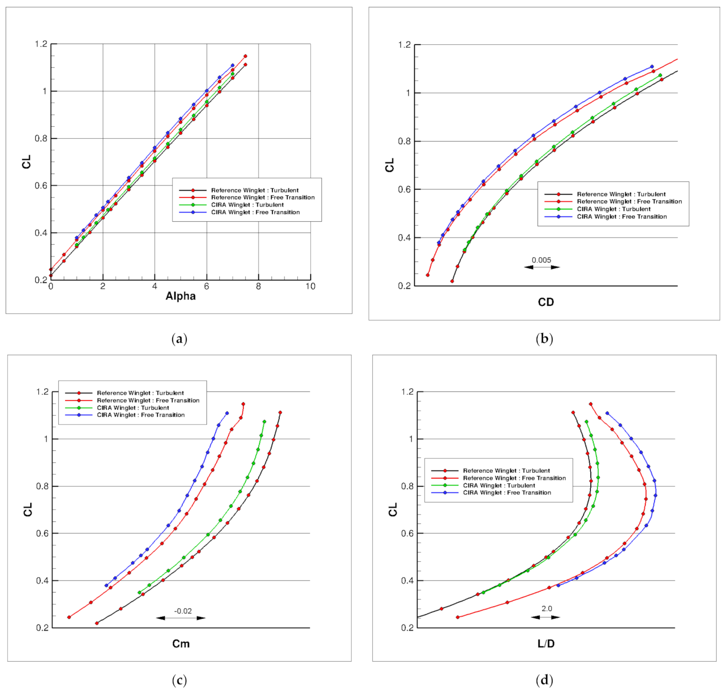
3.3. High Fidelity CFD Results and Performance Comparison at Design Points

In Figure 11, the resulting winglet aeroshape is compared with the reference one. It can be seen that the wingspan is slightly increased, and that its planform is more tapered than the reference one. Note that the same grid topology was used for the CFD computations and that the same reference wing area was considered for the aerodynamic coefficient.
In a first step, it is necessary to evaluate the performance of the new winglet with no morphing function enabled. When considering the pressure field on the winglet, it can be seen (Figure 12) that the load on the upper surface of the new winglet is more important than for the reference one at the nominal cruise conditions. Then, performances between the two winglets are compared at cruise conditions in Figure 13 for both fully turbulent and transition-free conditions. Black (turbulent) and red (laminar) curves are for the reference winglet, green (turbulent) and blue (laminar) curves for the new winglet. Performances in climb conditions have also been evaluated and similar trends have been observed. The CL(α) curve is nearly unaffected by the winglet change, and there is a slight improvement in the CD (or LoD) observed for the morphing winglet (see Table 1 for numerical values). A slight increase in pitching moment is also observed.
As a conclusion, the new winglet was selected as the wing tip device for the AG2-NLF plane, as it exhibits some aerodynamic improvements when compared to the reference one.

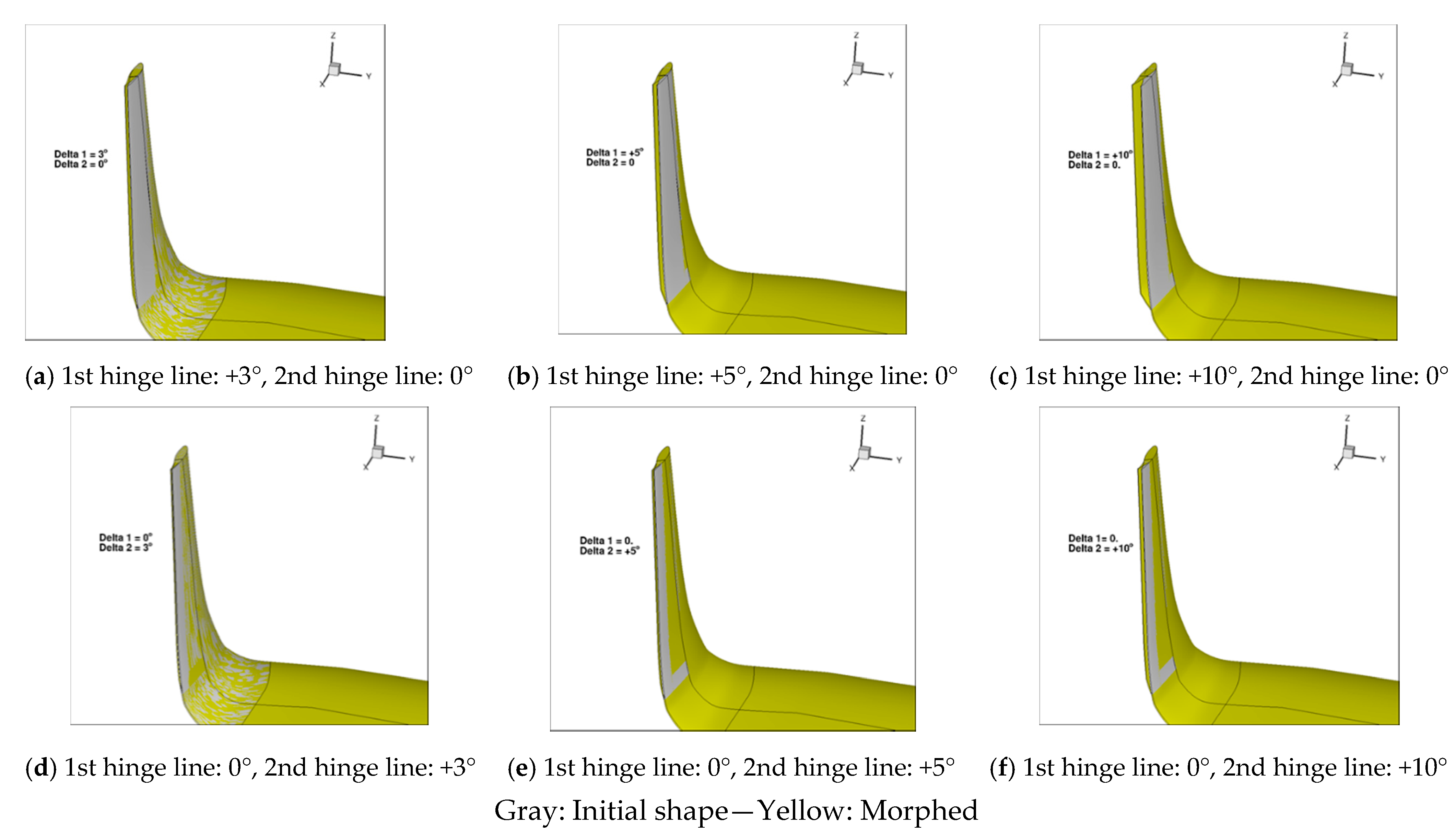
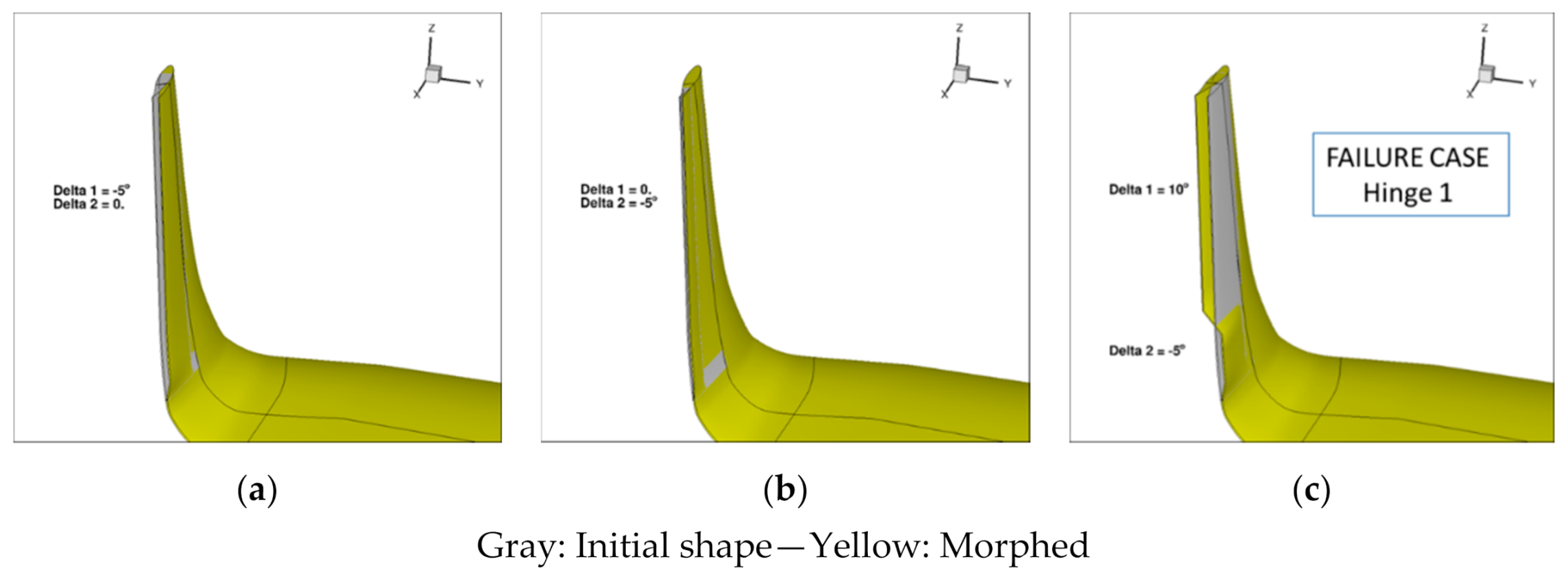
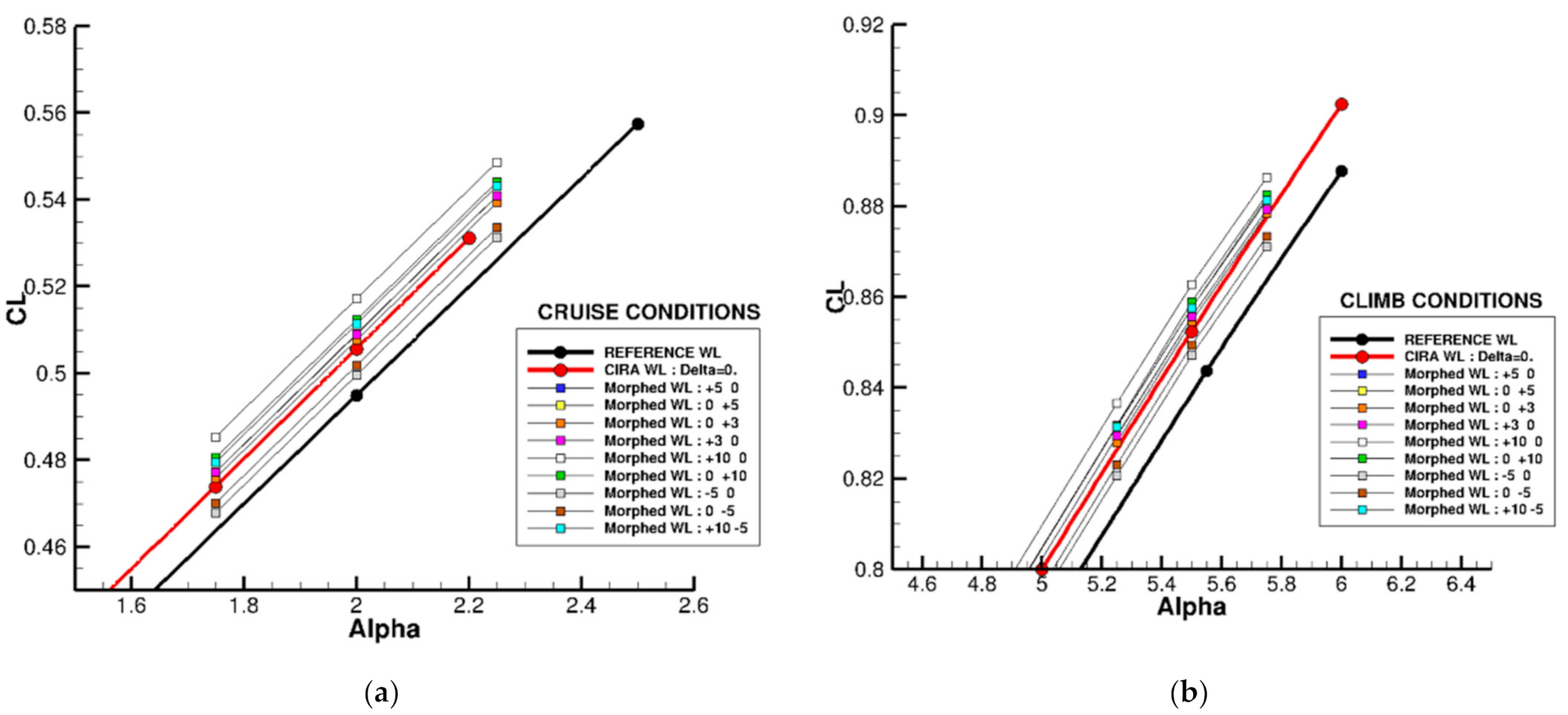
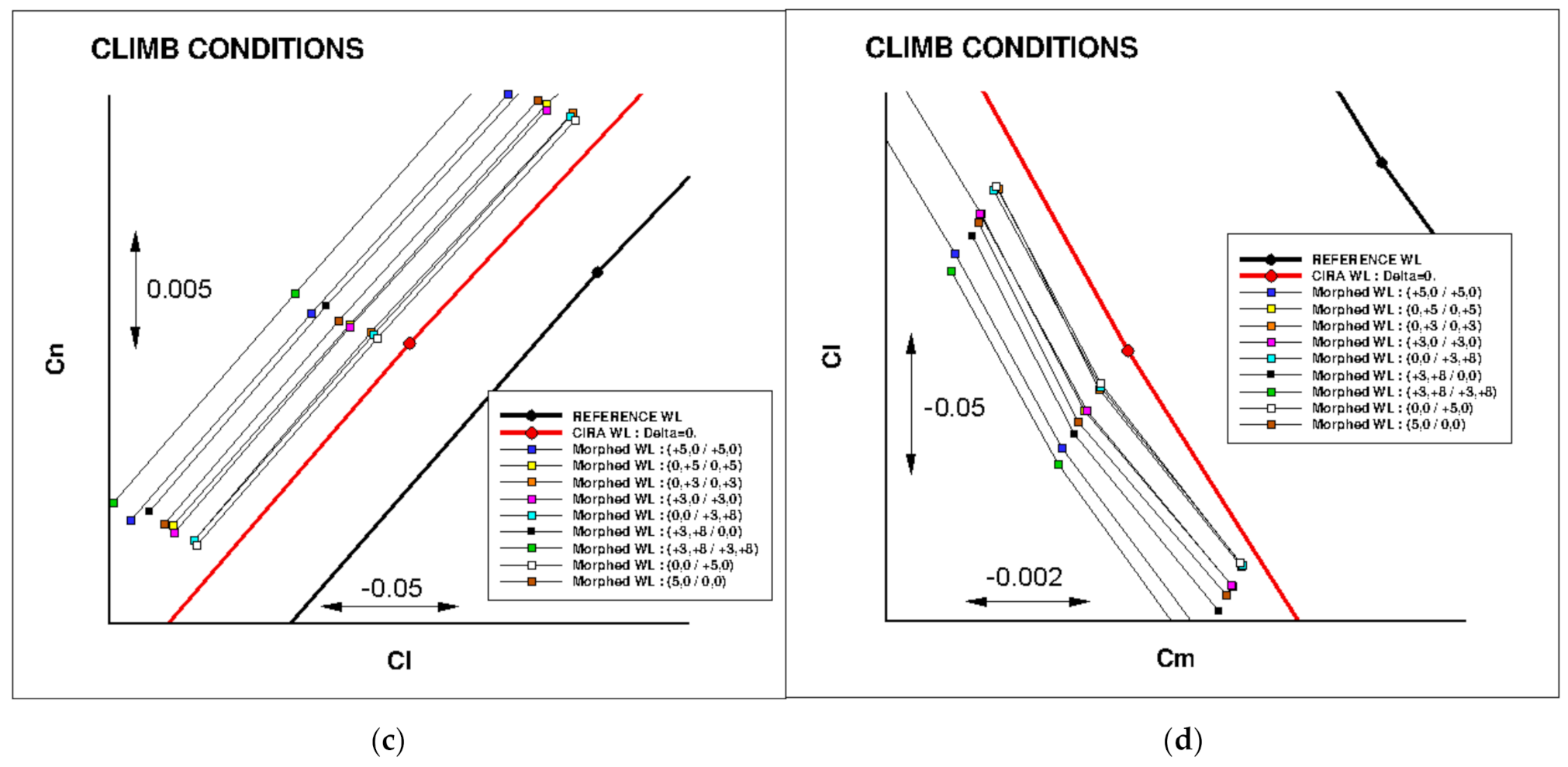
3.4. Study of Morphing Winglet Configurations

Then, the use of morphing flaps adapted to this winglet has been assessed in term of possible aerodynamic performances. The adopted convention considers a positive deflection when it moves outward. For the present analysis, the same deflection applied at the same hinge location was considered for the upper and lower flaps. Only one “failure” case, with positive deflection on the upper flap and negative on the lower flap, has been considered. Figure 14 presents the different configurations considered by CFD evaluations for positive flap deflections. The angles considered were 3°, 5° and 10°, applied either on hinge 1 (upper line) or hinge 2 (lower line).
Considering the negative deflections (Figure 15), only one case (−5°) was considered. Some problems occurred for larger negative values in the grid deformation tool, with local grid inversion leading to “negative cells” in the field, due to the concave topology used in the baseline grid. Finally, a kind of “failure” case was considered, with +10° deflection on the upper flap, and −5° for the lower flap, both applied on hinge 1.
Computations were carried out around the CL value, corresponding to the design cases. Several flight conditions have been considered and numerical results have been sent to partners for local force analysis on the different elements for sizing cases. In this paper, only the reference cruise (M = 0.52 @ 20,000 ft) and climb (M = 0.36 @ 15,000 ft) are presented. All the results presented in this document are at “aircraft” level. The force and moment coefficients considered the entire aircraft surfaces for pressure and friction integration.
Figure 16 presents the CL(α) curves computed at cruise or climb conditions for the different morphed winglet configurations considered. The results obtained for the Reference initial winglet (black curve) and the new winglet (CIRA winglet) with no morphing (red curve) are given for comparison. These results show that the morphed winglet device can be used as a surface control on the aircraft for load alleviation. As a basic result, it can be seen that the larger the deflection or the flap length, the larger the ΔCL. It can also be noted that some combinations are nearly equivalent in terms of CL(α). For instance, applying a global deflection of 3° on hinge 1 or 5° on hinge 2 leads to the same ΔCL.
In terms of improvements in the aerodynamic performance around the design flight point, the use of a morphed winglet seems very limited. Figure 17 presents the LoD obtained for the different configurations. At cruise conditions, there is no gain observed around the flight CL. Small positive deflections are nearly equivalent to the δ = 0° case. For climb conditions, there are some very small gains observed in LoD found (about +0.05) for most of the positive deflections. Note that this approach underestimated the actual system benefits, as morphing effect was simulated by plain rotations at the first and second hinge lines of the tabs.
Figure 18 compares the “Moment diagrams” at cruise and climb conditions. In these diagrams, improvements are present when the absolute value of the moment coefficient decreases. For instance, this corresponds to a trend from the new winglet to the reference one. As expected, the use of negative deflections decreases the absolute values of the different moment coefficients. For positive deflections, an increase is observed, but with a small amplitude for +3° (hinge 1 or 2) and +5° (hinge 2) cases. Note that for a possible aero-structural application, the case with −5° on hinge 2 could be used as a starting point. There are indeed small losses in aerodynamic efficiency, but these are balanced with a global decrease in the absolute values of the moment coefficients.

4. Active Load Alleviation Performance

Besides aerodynamic benefits, the morphing winglet design can exploit the movable control surfaces to carry out load alleviation tasks. Active load alleviation capability is obtained in this work by moving the winglet surfaces during the manoeuvre condition to reduce the resulting aerodynamic loads [45]. The main reason supporting this choice is the slow response of the winglet actuators which are designed to adjust the winglet deflection in slowly varying steady flight conditions, thus requiring a limited bandwidth. Higher actuators’ bandwidth would have led to an unnecessary weight and power consumption increase.

4.1. Static Aeroelastic Analysis

A static aeroelastic analysis is initially used to evaluate the best-case system performance, that is the one that can be obtained neglecting the slow response of the winglet actuator.

4.1.1. Model Definition

Steady structural response is assumed in the formulation of the dynamic equations for static aeroelastic analysis [46], this means that only the degrees of freedom associated with the rigid body response will appear in dynamic equations, while the elasticity will provide a correction of the rigid body matrices, leading to a set of motion equations written as:
M ¯ b b v ˙ b + C ¯ b b v b + F ¯ c u c = F ¯ g
where M ¯ b b and C ¯ b b are the rigid-body mass and damping matrices corrected with elastic and aerodynamic effects, v b is the vector containing the rigid body degrees of freedom, u c is a vector containing the control surface rotations and F ¯ c is the matrix defining the rigid body forces associated with the control surface rotation. F ¯ g is the weight force. No relationship between v b and v ˙ b is assumed in the solution of the dynamic equations.
The system of equation described above is underdetermined, and a set of additional relationships need to be introduced to fully define the manoeuvre condition, such as by imposing the angle of attack, the sideslip, the load factor or other quantities. All the constraints are expressed in the form
V 1 v ˙ b + V 2 v b + V c u c = b .
As stated in [47], when there are more control surfaces available than unconstrained degrees of freedom it is possible to reformulate the manoeuvre problem as a constrained optimization problem, where a quadratic cost function of the form is minimized. The dynamic equations is then used as a constraint equation in the optimization, along with the other constraint equations defining the manoeuvre defined above and additional constraints that limits the control surface rotations, expressed as:
J =   1 2 v ˙ b T v b T u c T S a a S a v S a c S v a S v v S v c S c a S c v S c c v ˙ b v b u c
δ l o w e r < δ < δ u p p e r
where δ l o w e r and δ u p p e r represents the lower and upper limits for the rotation of the control surface.

4.1.2. Controller Definition

The optimization system defined in the previous section was used to get the controller gains. The cost function was based on the minimization of the wing root bending moment and the trim solution then contained presented the combination of main control surface rotations and winglet rotation leading to the minimization of the bending moment at wing root, while satisfying the manoeuvre definition.

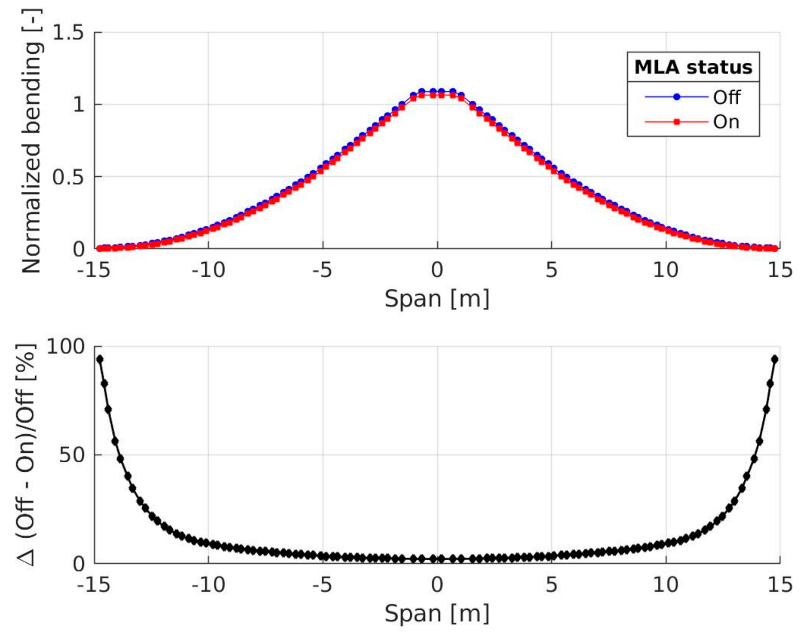
4.1.3. Simulation Results

A steady level flight condition is considered at sea level with Mach number M = 0.41 . A static pull up manoeuvre with load factor N z = 2.5 is used to evaluate the controller performance. The results in terms of structural loads are presented in Figure 19 considering the out-of-plane bending moment and normalizing the value with respect to the value at wing root.
A reduction in the structural loads was obtained, with a limited reduction at wing root, and a very significant reduction at wing tip. However, since retrofitting winglets to existing aircraft leads to increased structural loads at the outboard section of the wing, a controller capable to reduce structural loads at the outer wing sections is of particular interest, even if it provides only a limited alleviation in the inboard wing sections.

4.2. Aeroelastic State-Space Model of the A/C

Dynamic effects can be important in the definition of the structural loads in manoeuvres conditions, for this reason a full evaluation of the MLA performances requires also a dynamic evaluation of the manoeuvres.
In addition to dynamic aeroelastic effects, also the dynamic response of the actuators and the digital implementation of the controller may affect the results. The slow dynamic response of the actuators is reducing the effectiveness of the controller, since it delays the deflection of the winglet surfaces with respect to that of the main control surfaces, and a nonlinear dynamical model is used to reproduce this behaviour.
To consider all the aforementioned effects, a nonlinear time simulation of each manoeuvre is performed. The frequency-domain based aerodynamic forces described above cannot be used directly in a time simulation, but an approximated system is required. The identification method described in [48] is then used to express the system in state-space form
x ˙ a = A a x a + B a 0 u a + B a 1 u ˙ a + B a 2 u ¨ a f a q = C a x a + D a 0 u a + D a 1 u ˙ a + D a 2 u ¨ a
where u a = q T v g δ c T T .
The aeroelastic system is then expressed in state-space form as
x ˙ a e = A a e x a e + B g v g + B c δ c y a e = C a e x a e + D g v g + D c δ c
where the output vector y a e contains the parameters describing the rigid motion of the aircraft and the internal loads along the wing span.

4.3. Winglet Actuation Model

The aeroelastic system is coupled with a dynamic model of the winglet servoactuators. The servoactuator system includes the definition of both the physical actuator and the control logic, its input is the commanded winglet rotation while the output is the actual winglet rotation δ c . The actual winglet rotation is also affected by the aerodynamic and inertial hinge moment, which need to be provided to the actuator model as additional output of the aeroelastic system.
Each of the two movable portions of the winglet are moved by an Electromechanical Actuator (EMA). A numerical model of the EMA is connected to the system, accepting as an input the tension command from the servocontroller, the actuator shaft loads and the actuator position. The servocontroller is then used to drive the EMA to the commanded position.

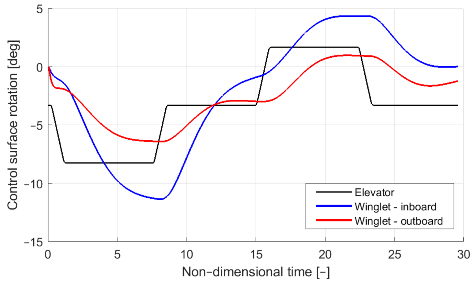
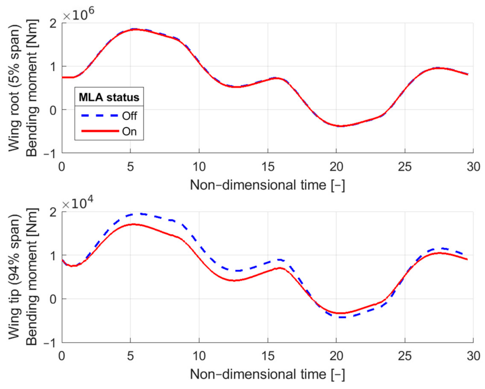
4.4. Time Simulation Results

The manoeuvres analysed with a static aeroelastic analysis were reproduced also using a dynamic simulation. A step deflection of the elevator is used to get the target load factor of 2.5 g . The time history of the command is shown in Figure 20 and includes both a negative and positive command, to have both pull-up and pull-down manoeuvres. The dynamics of the elevator actuation system is considered by introducing a 10 Hz bandwidth and a saturation for the deflection rate. The slow winglet response prevents it to reach the saturation limits, and the deflection is not identical in the two sections due to the different sizes that lead to different aerodynamic hinge moments and then to different actuator responses. The larger surface of the outboard winglet section, in particular, leads to a lower rotation.
The time history of wing internal loads shows that the MLA system is able to reduce structural loads even if the deflection values predicted in the static aeroelastic analysis are not reached in dynamic analyses. This is shown in Figure 21 where the bending moment both at wing root and at wing tip are shown. In the time histories the time has been non-dimensionalised considering as a reference the period of the first wing structural mode.

5. Structural Design and Systems Integration

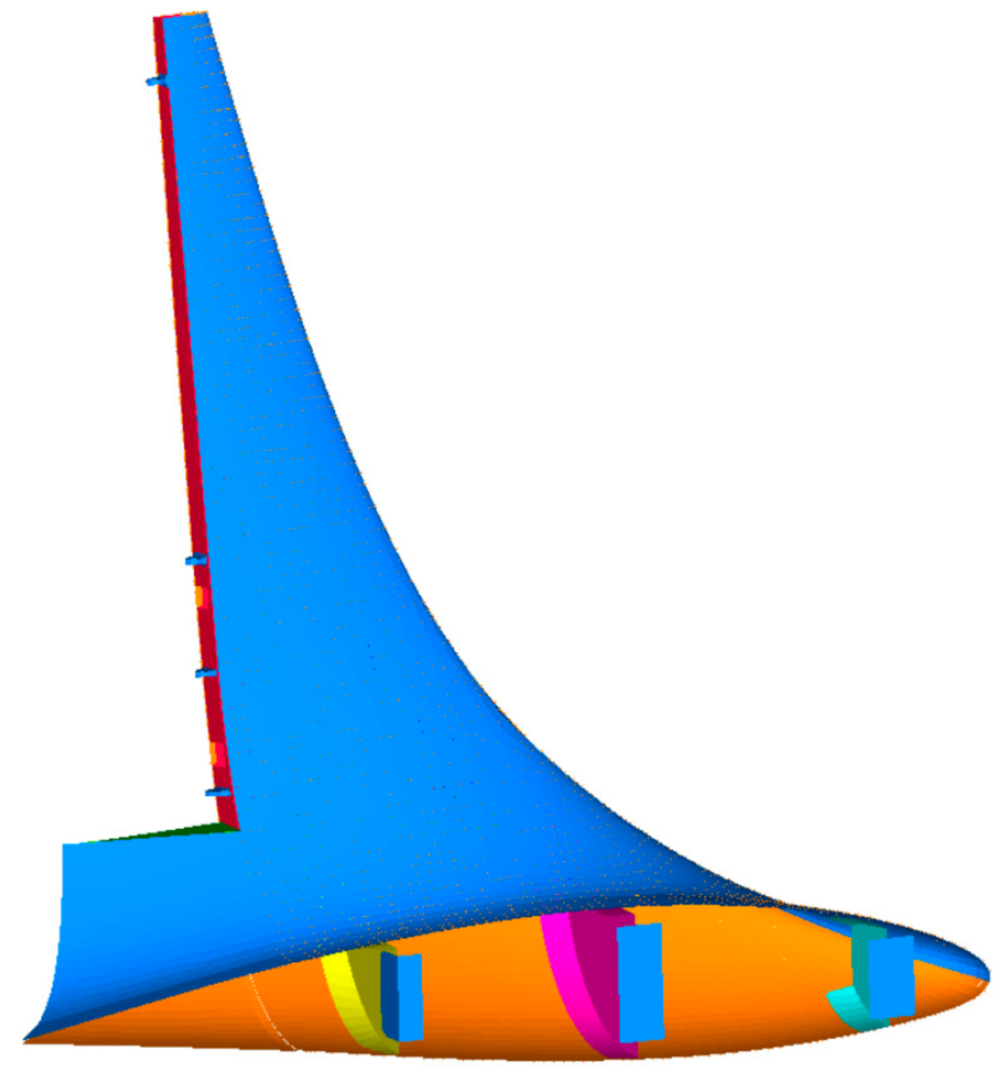
5.1. Preliminary Structural Layout

The structural layout of the morphing winglet consists of a passive and an active part. The former is made of laminate skin panels and a torsion box consisting of spars and ribs. The two morphing tabs incorporate a “finger-like mechanism”, shown in Figure 22 Winglet morphing is enabled by the relative rotations of three adjacent blocks, which are free to rotate around the hinges on the camber line, thus physically turning the camber line into an articulated chain of consecutive segments. Linking rods, hinged on non-adjacent blocks, force the camber line segments to rotate according to a specific gear ratio, which complies with the shapes that need to be achieved. Each tab is, therefore, a single-degree-of-freedom (SDOF) system; if rotation of any of the blocks is prevented, no change in shape can be obtained. On the contrary, if an actuator moves any of the blocks, all the other blocks follow the movement accordingly.

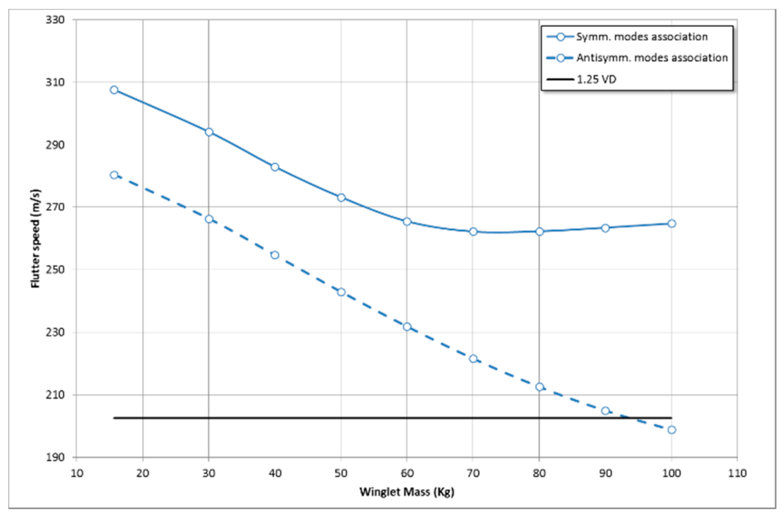
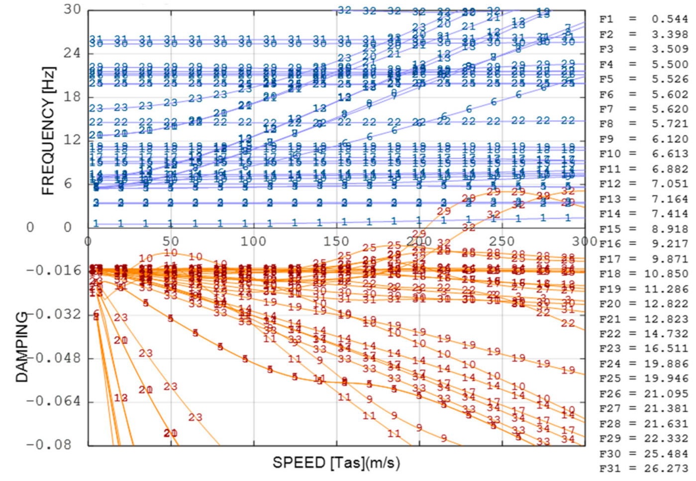
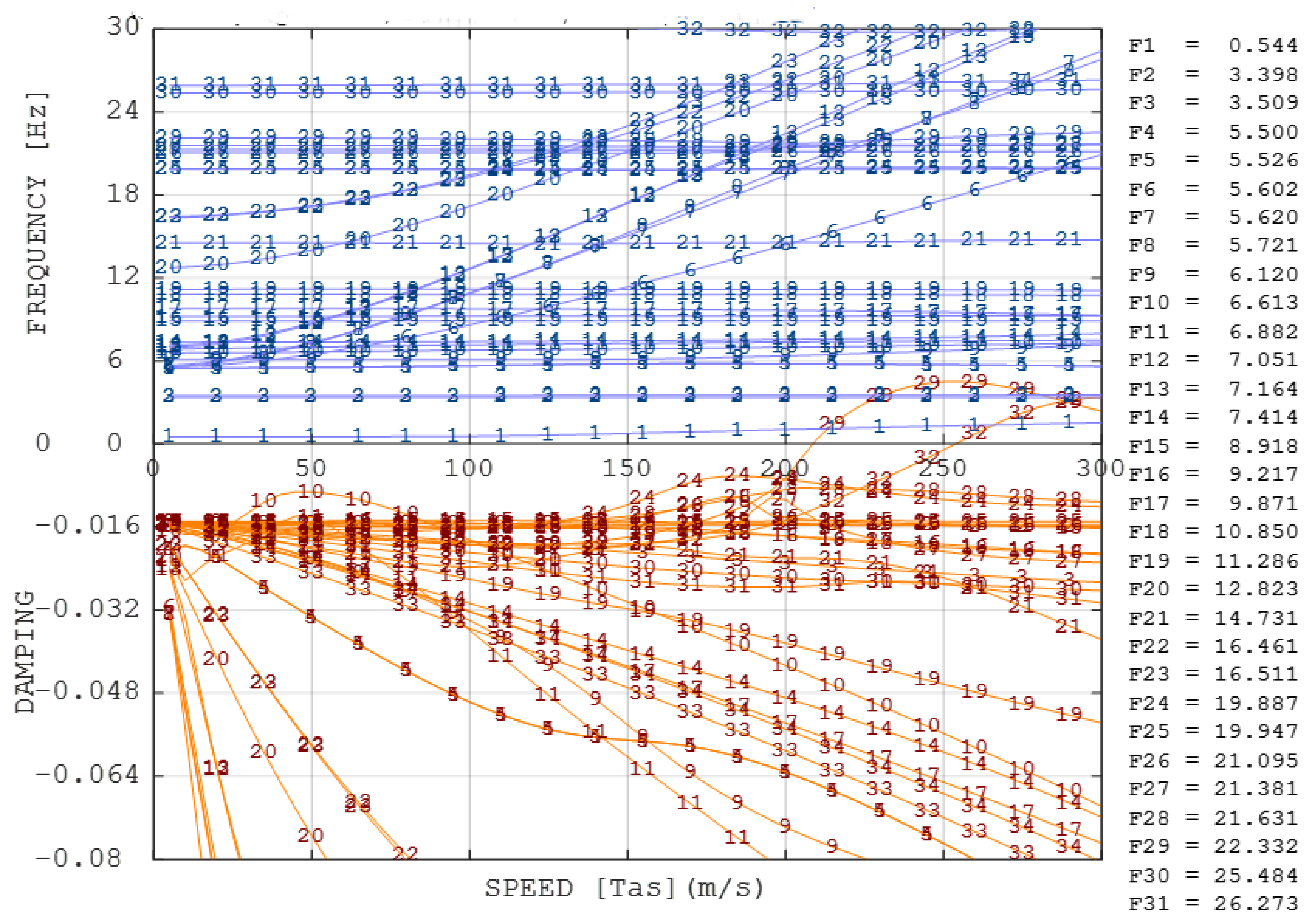
5.2. Aeroelastic Trade-Off

As for any safety-critical device, a preliminary assessment of morphing winglet on aircraft aeroelastic stability was judged to be extremely relevant to avoid the consolidation of an unsafe, and therefore unflyable, structural layout.
Flutter analyses were carried out in two consecutive phases; at first, trade-off investigations were addressed to establish the maximum allowable weight of the winglet structure.
To this aim, the entire device was modelled as a lumped mass placed at the wing tip; starting from the typical mass value of a conventional arrangement, the winglet mass was progressively increased until bending-torsion flutter of the wing was induced within the flight certification envelope (i.e., at a flight speed lower than 1.25, the aircraft dive speed VD). Bending/torsion flutter speed was estimated by referring to the Molyneux equation [49] and to the wing’s natural frequencies resulting from the model described in Section 2.4.1; both symmetric and anti-symmetric coupling mechanisms were considered.
It was found that only the flutter due to the coalescence of anti-symmetric wing bending and torsion was sensibly affected by the winglet mass increase (Figure 23); in order to assure aircraft flutter clearance, the overall mass of the imposed morphing winglet did not exceed the value of 90 Kg.
The preliminary structural design of the morphing winglet (Section 5.1) was carried out under this relevant inertial constraint and, once completed, a new loop of analyses was performed to verify the clearance from any other type of flutter induced by unstable couplings of winglet and wing modes.
The finite element model of the morphing winglet described in Section 5.3 was condensed into a dynamically equivalent set of beams, which were integrated into the overall aircraft aeroelastic model to replace those used for the simulation of the conventional winglet (Section 2.4.1). Winglet movables were also modelled through equivalent beams, and the rotation around their longitudinal axis was constrained by means of grounded springs reproducing the stiffness of the actuators in power-on mode.
The aircraft aeroelastic stability equation was solved in the space of modal coordinates and in the frequency domain; the critical speeds were evaluated by means of PK-method [50] under the following assumptions:
  • Association of the theoretical elastic modes up to 60 Hz;
  • Modal damping conservatively set to 1.5% for all the elastic modes;
  • All moveable surfaces in control-fixed attitude;
  • Sea-level flight altitude;
  • Flight speed range: (0: 200 m/s) 200 m/s being equal to 1.25*VD as for certification requirements.
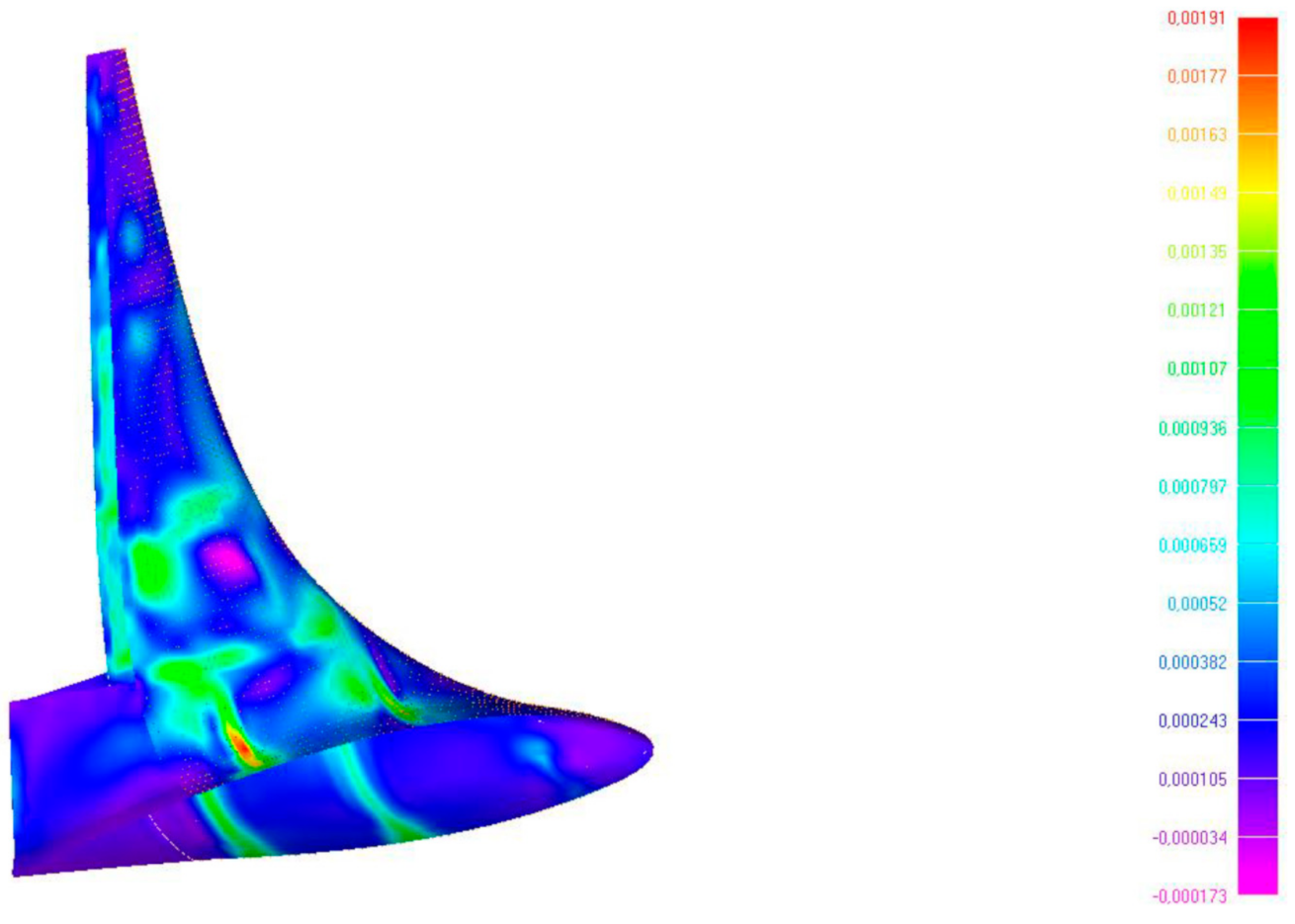
All flutter calculations and the elaboration of Vg plots were made in SANDY software environment [51].
A flutter due to the coupling of winglet movable harmonics and winglet bending/torsion was found at a critical speed of nearly 200 m/s (Figure 24). The flutter dynamics were proven to be induced by a typical underbalanced behaviour of the movables. To increase the margin of safety with respect to flutter, the degree of mass-balancing of each movable was then increased up to 0.7, which successfully led to a first critical speed of nearly 210 m/s (Figure 25). In such a configuration, a further flutter speed was also detected; nevertheless, since it was much higher than 200 m/s, it was considered not critical for the safety of the reference aircraft.

5.3. FE Model

An FE model was developed to fully represent the 3D CAD of the morphing winglet device. Here, the focus is on the passive structure of the winglet, designed to withstand the overall structural loads. The main substructures are: CFRP upper and lower panels and internal CFRP spars and ribs. Such components were FE modelled by 10,593 2D quad elements, shown in Figure 26, derived from the middle planes of the components.
The upper and lower skins are composed of fabric layers. UD-plies in x direction are used for reinforcement. The spars and ribs are composed of fabric layers. The thickness of the laminates is between 2.7 and 3.6 mm. The weight was well below the preliminary target of 50 kg.
A number of load cases were considered for the structural design of the morphing winglet, in compliance with the CS25 (manoeuvres, gust, landing, engine failure) airworthiness regulation. Such loads were intended to be limit loads, i.e., the loads that the structure must be able to support without detrimental permanent deformation.
For the analysis of the laminates, a maximum/minimum strain criterion in 11- and 22-direction was used. Additionally, stress was also evaluated in 11-, 22- and 12-directions, but only to check. The ply stresses and strains for the failure analysis were read from the FEM results. The reserve factors for each ply of an element were then calculated. The enveloped results were then elaborated to allow for computation of the minimum reserve factors. An example of maximum principal strain computed on the skin for one of the sizing cases is shown in Figure 27.

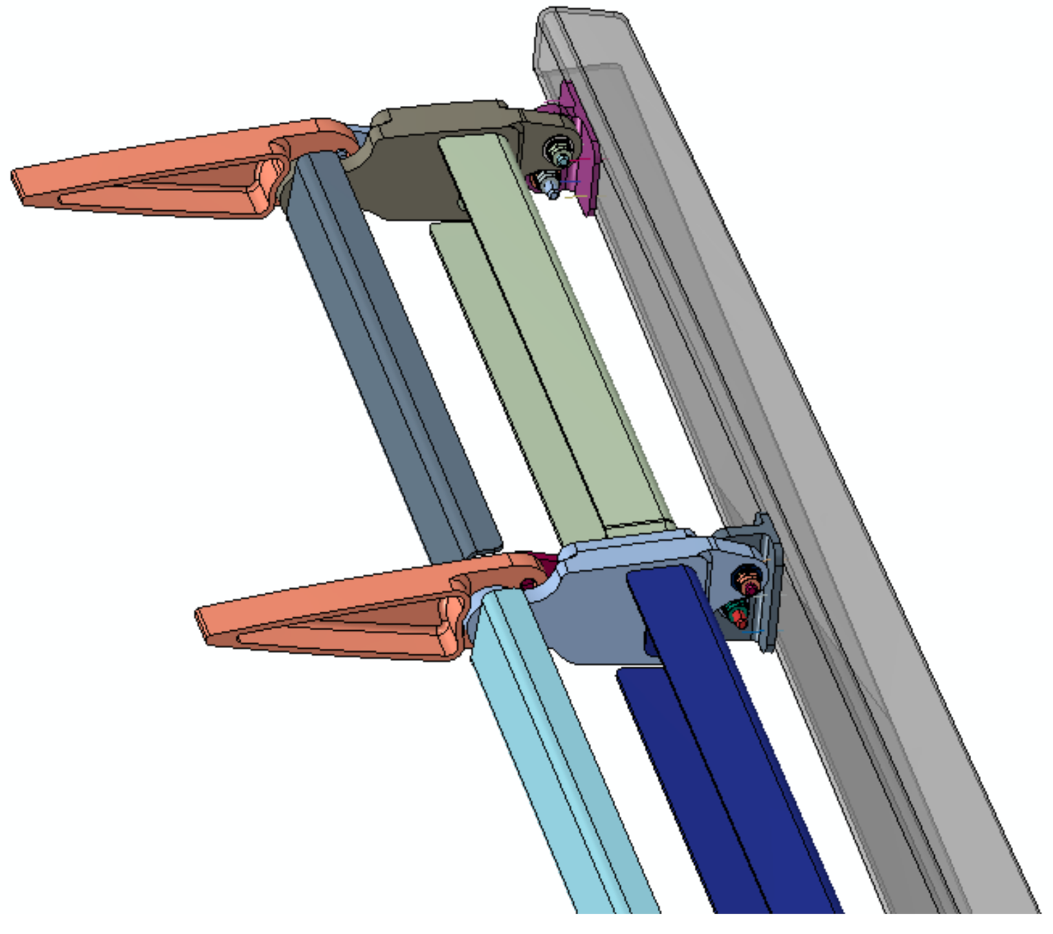
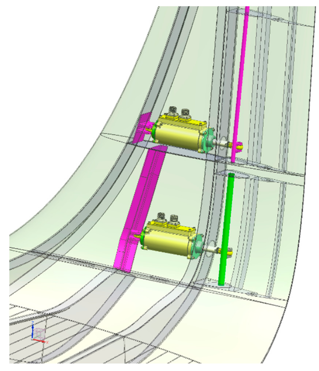
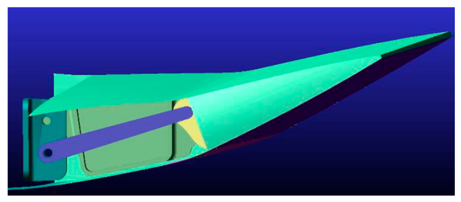
5.4. Actuation Layout

A further step of the integrated design of a morphing winglet involves the preliminary assessment of the actuation system, including both the installation and performance requirements. It is worth noting that both influence the effective reproduction of the given aeroshapes under aerodynamic loads.
In light of the limited space available within the winglet box to accommodate both the winglet actuators and actuation chains, several installation trade-off studies were carried out to achieve the best configuration. A linear electromechanical actuation was considered for each mechanical drive of the two independent surfaces. Such an approach assumes that, in principle, a flight-worthy actuator of adequate size, weight, and power will be developed to withstand the hinge moments due to the aerodynamic loads.
The actuation chains addressed in this paper are controlled by two separate actuators, one for each surface, positioned at different winglet heights [17] (see Figure 28).
Such a direct actuation layout, based on a crankshaft design, has the advantages of relative installation simplicity, lower weight, and higher stiffness, with additional benefits in terms of assembly time and maintenance.
Parameter studies and motion optimization were studied through a multibody model developed in MSC/Adams. The upper morphing surface deployment and its comparison with the given aeroshape is shown in Figure 29. This allowed for a comparison of the actual rotation of the tab with the nominal (expected) values enabling the load control function. A static actuation law was then implemented. As a result, the actuator rod stroke was correlated with the resulting tab rotation. Both functions are reported in Figure 30 and Figure 31, respectively. For the given geometrical parameters, the actuators’ performance requirements were then derived (see Table 2). Operating and maximum static axial loads were about 3.5 and 5 kN, respectively. The maximum speed foreseen for the load control function was in the order of 5 mm/s.

6. Conclusions

A morphing winglet has the potential to combine aerodynamic and structural benefits more efficiently than a conventional fixed wingtip surface. A fault-tolerant concept based on two individual (asynchronous) morphing surfaces (upper and lower) was investigated in this work in order to enhance aerodynamic efficiency and reduce maneuver loads on a regional transport aircraft.
A low-fidelity design tool was used to preliminarily design the winglet aeroshape and predict the related aerodynamic benefits without moving the adaptive tabs. Then, high-fidelity CFD analyses were proven to provide aircraft with reduced induced drag compared to the reference counterpart.
Different morphed aeroshapes were considered. It was found that such a device can be used as control surface on the aircraft for load alleviation, as a deflection of the tabs acts directly on the CL(α) curve. Concerning the load control, limited improvements were proven. However, it was found that some configurations may be used for a global aero-elastic optimization as a decrease in aerodynamic performance could be balanced by an improvement in moment coefficients at aircraft level, and, therefore, wing structure mass benefits could be obtained. The combined use of morphing devices adapted to the wing configuration equipped with the morphing winglet leads to about 3% drag reduction at climb conditions with respect to the reference winglet shape with no morphing applied.
Attention was also paid to the design and performance of a load-alleviation controller driving the hinged tabs to reduce wing loads in maneuvering conditions. A feed-forward architecture based on a direct measurement of the deflection of the main control surfaces was considered. The results demonstrate that the proposed mechanical system is able to reduce the wing loads in different flight conditions (including the sizing ones). Additionally, although the actuator dynamics reduce the performances that can be obtained with the MLA controller, the system was shown to reduce the wing structural loads.
Finally, structural analyses were carried out to confirm the actual feasibility of the device and to preliminarily estimate its weight, which was well below the preliminary target of 50 kg. For structural verification, the worst load cases within minimum and maximum internal forces (bending and torque) were considered. An FE model, with its geometry and material properties, was processed to size the laminate skin panels and the winglet torsion box made of spars and ribs. Trade-off aero-elastic assessments were carried out to predict the flutter speed with different winglet mass values. Actuation kinematics were studied through a multibody model by correlating the actuator rod strokes with the resulting tab rotations.
Further studies are planned to assess the behavior of the structure by considering the actuation chain’s contribution to the overall stiffness of the morphing device. A structural optimization process is also envisaged with respect to a set of failure criteria. Because of the importance of aeroelastic phenomena, further development will focus on aeroelastic stability margins and the safety-related implications of actuator failures.

Author Contributions

Conceptualization, I.D.; methodology, I.D., F.M., R.P.; software, G.A., R.P.; validation, R.P. and A.C.; formal analysis, I.D., R.P.; investigation, F.F.; resources, F.F.; data curation, F.M.; writing—original draft preparation, I.D.; writing—review and editing, A.C.; visualization, G.A.; supervision, I.D.; project administration, A.C.; funding acquisition, A.C. All authors have read and agreed to the published version of the manuscript.

Funding

Part of the research described in this paper has been carried out in the framework of AIRGREEN2 Project, which gratefully received funding from the Clean Sky 2 Joint Undertaking, under the European’s Union Horizon 2020 research and innovation Program, Grant Agreement No. 807089—REG GAM 482 2018—H2020-IBA-CS2-GAMS-2017.

Institutional Review Board Statement

Not applicable.

Informed Consent Statement

Not applicable.

Data Availability Statement

Not applicable.

Acknowledgments

The research leading to these results has received funding from the European Community’s Seventh Framework Program (FP7/2007–2013) for the Clean Sky Joint Technology Initiative under grant agreement CSJU-GAM-GRA-2008-001 and the European Community’s Horizon 2020—the Framework Program for Research and Innovation (2014–2020) for the Clean Sky Joint Technology Initiative under grant agreement CS2-REG-GAM-2014-2015-01. The authors would like to acknowledge Dr. Ing. G. Carossa at Leonardo S.p.A. (Aircraft Division) for supervising the research reported in this manuscript.

Conflicts of Interest

The authors declare no conflict of interest.

Nomenclature

A/CAircraft
AG2Airgreen 2 project
AG2-NLFRegional aircraft of the AIRGREEN2 project equipped with the NLF wing
CFDComputational Fluid Dynamics
CS2Clean Sky 2
CLLift coefficient
CDDrag coefficient
EMAElectromechanical actuators
LCALoad Control and Alleviation
LoDLift over Drag ratio
MLAManeuver Load Alleviation
NLFNatural Laminar Flow
TP9090-passenger Regional Turboprop Aircraft

References

  1. Holle, A.A. Plane and the Like for Aeroplanes. U.S. Patent No.1225711, 8 May 1917. [Google Scholar]
  2. Parker, H.F.; National Advisory Committee for Aeronautics. The Parker Variable Camber Wing, NACA Technical Report 77; 1920. Retrieved 7 April 2016. Available online: https://digital.library.unt.edu/ark:/67531/metadc65726/ (accessed on 9 February 2021).
  3. Culick, F. Wright brothers: First aeronautical engineers and test pilots. In Proceedings of the 45th Annual Symposium The Society of Experimental Test Pilots, Los Angeles, CA, USA, 26–29 September 2001. [Google Scholar]
  4. Ader, C. Appareille Aile‘ Pour la Navigation Aerienne. France Patent No.205155, 11 August 1890. [Google Scholar]
  5. Smith, J.W.; Lock, W.P.; Payne, G.A. Variable-Camber Systems Integration and Operational Performance of the AFTI/F-111 Mission Adaptive Wing; NASA Technical Memorandum TM-4370; National Aeronautics and Space Administration: Edwards, CA, USA, April 1992.
  6. Hilbig, R.; Koerner, H. Aerodynamische Entwicklungsrichtungen fuer Verkehrsflugzeuge, Deutsche Gesellschaft fuer Luft-und Raumfahrt (DGLR). In Proceedings of the DGLR Annual Convention 1984, Hamburg, Germany, 1–3 October 1984. [Google Scholar]
  7. Kudva, J.N. Overview of the DARPA smart wing project. J. Intell. Mater. Syst. Struct. 2004, 15, 261–267. [Google Scholar]
  8. NASA; US AFRL. Adaptive Compliant Trailing Edge Flight Experiment; RC Soaring Digest: Olalla, WA, USA, 2014; Volume 31, pp. 85–86. [Google Scholar]
  9. Kuzmina, S.; Ishmuratov, F.; Zichenkov, M.; Chedrik, V.; Amiryants, G.A.; Kulesh, V.; Malyutin, V.; Chedrik, A.; Timokhin, V.; Shalaev, S.; et al. Wind Tunnel Testing of Adaptive Wing Structures. Morphing Wing Technol. 2018, 1, 713–755. [Google Scholar]
  10. Wildschek, A.; Storm, S.; Herring, M.; Drezga, D.; Korian, V.; Roock, O. Design, Optimization, Testing, Verification, and Validation of the Wingtip Active Trailing Edge. In Smart Intelligent Structures (SARISTU); Springer: Berlin/Heidelberg, Germany, 2016; pp. 219–255. [Google Scholar]
  11. Cooper, J.E.; Chekkal, I.; Cheung, R.C.M.; Wales, C.; Allen, N.J.; Lawson, S.; Peace, A.J.; Cook, R.; Standen, P.; Hancock, S.D.; et al. Design of a Morphing Wingtip. AIAA J. Aircr. 2015, 52. [Google Scholar] [CrossRef] [Green Version]
  12. Liauzun, C.; le Bihan, D.; David, J.M.; Joly, D.; Paluch, B. Study of Morphing Winglet Concepts Aimed at Improving Load Control and the Aeroelastic Behavior of Civil Transport Aircraft. Aerosp. Lab. J. 2018, 14, 1–15. [Google Scholar]
  13. Ameduri, S.; Concilio, A.; Dimino, I.; Pecora, R.; Ricci, S. AIRGREEN2—Clean Sky 2 programme: Adaptive wing technology maturation, challenges and perspectives. In Proceedings of the ASME conference on smart materials, adaptive structures and intelligent systems, San Antonio, TX, USA, 10–12 September 2018; Paper no. SMASIS2018-8235. ASME: New York, NY, USA, 2018. [Google Scholar]
  14. Moens, F. Augmented Aircraft Performance with the Use of Morphing Technology for a Turboprop Regional Aircraft Wing. Biomimetics 2019, 4, 64. [Google Scholar] [CrossRef] [Green Version]
  15. De Gaspari, A.; Moens, F. Aerodynamic Shape Design and Validation of an Advanced High-Lift Device for a Regional Aircraft with Morphing Droop Nose. Int. J. Aerosp. Eng. 2019, 2019, 7982168. [Google Scholar] [CrossRef] [Green Version]
  16. Dimino, I.; Ameduri, S.; Concilio, A. Preliminary failure analysis and structural design of a morphing winglet for green regional aircraft. In Proceedings of the ASME 2018 Conference on Smart Materials, Adaptive Structures and Intelligent Systems (SMASIS2018), San Antonio, TX, USA, 10–12 September 2018. [Google Scholar]
  17. Dimino, I.; Gallorini, F.; Palmieri, M.; Pispola, G. Electromechanical Actuation for Morphing Winglets. Actuators 2019, 8, 42. [Google Scholar] [CrossRef] [Green Version]
  18. Noviello, M.C.; Dimino, I.; Concilio, A.; Amoroso, F.; Pecora, R. Aeroelastic Assessments and Functional Hazard Analysis of a Regional Aircraft Equipped with Morphing Winglets. Aerospace 2019, 6, 104. [Google Scholar] [CrossRef] [Green Version]
  19. Pecora, R.; Amoroso, F.; Noviello, M.C.; Concilio, A.; Dimino, I. Aeroelastic Stability Analysis of a Large Civil Aircraft Equipped with Morphing Winglets and Adaptive Flap Tabs. In Proceedings of the SPIE. 10595, Active and Passive Smart Structures and Integrated Systems XII, Bellingham, WA, USA, 4–8 March 2018. [Google Scholar]
  20. Verrastro, M.; Dimino, I. Morphing devices: Safety, reliability, and certification prospects. In Morphing Wing Technologies: Large Commercial Aircraft and Civil Helicopters; Elsevier Inc.: Amsterdam, The Netherlands, 2018; pp. 647–682. ISBN 9780081009642. [Google Scholar] [CrossRef]
  21. Regional Aircraft Innovation Takes a Great Leap Forward. Available online: https://cordis.europa.eu/article/id/422623-regional-aircraft-innovation-takes-a-great-leap-forward (accessed on 9 February 2021).
  22. Cambier, L.; Heib, S.; Plot, S. The Onera elsA CFD Software: Input from Research and Feedback from Industry. Mech. Ind. 2013, 14, 159–174. [Google Scholar] [CrossRef] [Green Version]
  23. Jameson, A.; Schmidt, W.; Turkel, E. Numerical Solutions of the Euler Equations by Finite Volume Methods Using Runge-Kutta Time Stepping. In Proceedings of the 14th Fluid and Plasma Dynamics Conference, Palo Alto, CA, USA, 23–25 June 1981. [Google Scholar]
  24. Spalart, P.R. Strategies for Turbulence Modelling and Simulation. Int. J. Heat Fluid Flow 2000, 21, 252–263. [Google Scholar]
  25. Wölcken, P.; Papadopoulos, M. (Eds.) Smart Intelligent Aircraft Structures (SARISTU): Proceedings of the Final Project Conference; Springer: Berlin/Heidelberg, Germany, 2016. [Google Scholar]
  26. Concilio, A.; Dimino, I.; Lecce, L.; Pecora, R. Morphing Wing Technologies. Large Commercial Aircraft and Civil Helicopters; Butterworth-Heinemann: Oxford, UK, 2018. [Google Scholar]
  27. Moens, F.; Perraud, J.; Krumbein, A.; Toulorge, T.; Iannelli, P.; Hanifi, A. Transition Prediction and Impact on 3D High-Lift Wing Configuration. In Proceedings of the 25th AIAA Applied Aerodynamics Conference, Miami, FL, USA, 25–28 June 2007. [Google Scholar]
  28. Cavagna, L.; Ricci, S.; Travaglini, L. NeoCASS: An integrated tool for structural sizing, aeroelastic analysis and MDO at conceptual design level. Prog. Aerosp. Sci. 2011, 47, 621–635. [Google Scholar]
  29. Ghiringhelli, G.L.; Masarati, P.; Mantegazza, P. Multibody implementation of finite volume C beams. AIAA J. 2000, 38, 131–138. [Google Scholar]
  30. Albano, E.; Rodden, W.P. A doublet-lattice method for calculating lift distributions on oscillating surfaces in subsonic flows. AIAA J. 1969, 7, 279–285. [Google Scholar] [CrossRef]
  31. Allen, J.B. Articulating Winglets. U.S. Patent 5,988,563 A, 23 November 1999. [Google Scholar]
  32. Irving, J.; Davies, R. Wing Tip Device. U.S. Patent 7,275,722 B2, 2 October 2007. [Google Scholar]
  33. Wildschek, A.; Prananta, B.; Kanakis, T.; van Tongeren, H.; Huls, R. Concurrent Optimization of a Feed-Forward Gust Loads Controller and Minimization of Wing Box Structural Mass on an Aircraft with Active Winglets. In Proceedings of the 16th AIAA/ISSMO Multidisciplinary Analysis and Optimization Conference, Dallas, TX, USA, 22–26 June 2015; American Institute of Aeronautics and Astronautics: Reston, VA, USA, 2015; pp. 1–24. [Google Scholar] [CrossRef]
  34. Gatto, A.; Bourdin, P.; Friswell, M.I. Experimental Investigation into the Control and Load Alleviation Capabilities of Articulated Winglets. Int. J. Aerosp. Eng. 2012, 2012, 789501. [Google Scholar] [CrossRef]
  35. Concilio ADimino, I.; Pecora, R. SARISTU: Adaptive Trailing Edge Device (ATED) design process review. Chin. J. Aeronaut. 2020. [Google Scholar] [CrossRef]
  36. Pecora, R.; Concilio, A.; Dimino, I.; Amoroso, F.; Ciminello, M. Structural design of an adaptive wing trailing edge for enhanced cruise performance. In Proceedings of the 24th AIAA/AHS Adaptive Structures Conference, San Diego, CA, USA, 4–8 January 2016. [Google Scholar]
  37. Pecora, R.; Amoroso, F.; Magnifico, M.; Dimino, I. Concilio, KRISTINA: Kinematic rib-based structural system for innovative adaptive trailing edge. In Proceedings of the SPIE—The International Society for Optical Engineering, Las Vegas, NV, USA, 20–24 March 2016; Volume 9801, p. 980107. [Google Scholar]
  38. Amendola, G.; Dimino, I.; Concilio, A.; Magnifico, M.; Pecora, R. Numerical design of an adaptive aileron. In Proceedings of the SPIE—The International Society for Optical Engineering, Las Vegas, NV, USA, 20–24 March 2016; Volume 9803, p. 98032. [Google Scholar] [CrossRef]
  39. Amendola, G.; Dimino, I.; Concilio, A.; Amoroso, F.; Pecora, R. Preliminary design of an adaptive aileron for the next generation regional aircraft. J. Theor. Appl. Mech. 2017, 55, 307–316. [Google Scholar] [CrossRef] [Green Version]
  40. Amendola, G.; Dimino, I.; Concilio, A.; Pecora, R.; Amoroso, F.; Lecce, L. Technological demonstration of an adaptive aileron system. In Proceedings of the SPIE 10593, Bioinspiration, Biomimetics, and Bioreplication VIII, Denver, CO, USA, 27 March 2018; p. 1059304. [Google Scholar] [CrossRef]
  41. Iuliano, E.; Andreutti, G.; Quagliarella, D.; Vitagliano, P.L. Evolutionary-Based Aero-Structural Optimization of a Joined Wing UAV Using Advanced Potential Methods. In Proceedings of the ECCOMAS 2008 Conference, Venice, Italy, 30 June–4 July 2008. [Google Scholar]
  42. Drela, M.; Youngren, H. AVL 3.36 User Primer. 2017. Available online: http://web.mit.edu/drela/Public/web/avl/avl_doc.txt (accessed on 9 February 2021).
  43. Vitagliano, P.L.; Quagliarella, D. A hybrid genetic algorithm for constrained design of wing and wing-body configurations. In Proceedings of the Conference on Evolutionary Methods for Design, Optimization and Control Applications to Industrial and Societal Problems, Barcelona, Spain, 15–17 September 2003. [Google Scholar]
  44. Deb, K. Multi-Objective Optimization Using Evolutionary Algorithms; John Wiley & Sons Inc.: New York, NY, USA, 2001. [Google Scholar]
  45. Fonte, F.; Iannaccone, G.; Cimminiello, N.; Dimino, I.; Ricci, S. Active Load Control of a Regional Aircraft Wing Equipped With Morphing Winglets. In Proceedings of the ASME 2018 Conference on Smart Materials, Adaptive Structures and Intelligent Systems. Volume 1: Development and Characterization of Multifunctional Materials; Modeling, Simulation, and Control of Adaptive Systems; Integrated System Design and Implementation, San Antonio, TX, USA, 10–12 September 2018. V001T04A021. [Google Scholar] [CrossRef]
  46. Rodden, W.P.; Love, J.R. Equations of motion of a quasisteady flight vehicle utilizing restrained static aeroelastic characteristics. J. Aircr. 1985, 22, 802–809. [Google Scholar] [CrossRef]
  47. Fonte, F.; Toffol, F.; Ricci, S. Design of a wing tip device for active maneuver and gust load alleviation. In Proceedings of the 2018 AIAA/ASCE/AHS/ASC Structures, Structural Dynamics, and Materials Conference, AIAA SciTech Forum, (AIAA 2018-1442), Kissimmee, FL, USA, 8–12 January 2018. [Google Scholar]
  48. Ripepi, M.; Mantegazza, P. Improved Matrix Fraction Approximation of Aerodynamic Transfer Matrices. AIAA J. 2013, 51, 1156–1173. [Google Scholar] [CrossRef]
  49. Molyneux, W.G. The Flutter of Swept and Unswept: Wings with Fixed-Root Conditions; Technical Reports No. 2796; Aeronautical Research Council: London, UK, 1954. [Google Scholar]
  50. Broadbent, E.G. Flutter and Response Calculations in Practice. In AGARD Manual on Aeroelasticity; AGARD: Neuilly-sur-Seine, France, 1963; Volume 3, Chapter 4. [Google Scholar]
  51. Arena, M.; Concilio, A.; Pecora, R. Aero-servo-elastic design of a morphing wing trailing edge system for en-hanced cruise performance. Aerosp. Sci. Technol. 2019, 86. [Google Scholar] [CrossRef]
Figure 1. Reference TP90 aircraft [21] (© REG IADP Consortium Members).
Applsci 11 02439 g001
Figure 2. AG2-NLF plane: Computed transition location on the wing upper surface at cruise conditions (M = 0.52 @ 20,000 ft). Blue = laminar, Red = turbulent.
Applsci 11 02439 g002
Figure 3. AG2-NLF plane: Computed transition location on the wing lower surface at cruise conditions (M = 0.52 @ 20,000 ft). Blue = laminar, Red = turbulent.
Applsci 11 02439 g003
Figure 4. AG2-NLF plane at cruise conditions (M = 0.52 @ 20,000 ft)—Computed aerodynamic performance. (a) Drag Polar (CL(CD)) curve; (b) CL(CL/CD) curve.
Applsci 11 02439 g004
Figure 5. Structural model of the regional transport aircraft.
Applsci 11 02439 g005
Figure 6. Aerodynamic model of the regional transport aircraft.
Applsci 11 02439 g006
Figure 7. Winglet control surfaces.
Applsci 11 02439 g007
Figure 8. Sketch of the morphing winglet [18].
Applsci 11 02439 g008
Figure 9. Tool for winglet aerodynamic shape optimization.
Applsci 11 02439 g009
Figure 10. Morphing winglet stations for parametrization.
Applsci 11 02439 g010
Figure 11. Comparison of reference and CIRA winglets.
Applsci 11 02439 g011
Figure 12. Comparison of the pressure distributions on the winglet at design cruise point (M = 0.52 @ 20,000 ft, CL = 0.50). (a) reference winglet, (b) CIRA winglet.
Applsci 11 02439 g012
Figure 13. Reference and CIRA winglets: comparison of aerodynamic performance at cruise conditions (M = 0.52 @ 20,000 ft). (a) Lift Polar (CL(α)); (b) Drag Polar (CL(CD)); (c) CL (Cm)curve, (d) CL (CL/CD) curve.
Applsci 11 02439 g013
Figure 14. Morphed winglet configurations considered: Positive deflections.
Applsci 11 02439 g014
Figure 15. Morphed winglet configurations considered: Negative deflections and failure case. (a) 1st hinge line: −5°, 2nd hinge line: 0°; (b) 1st hinge line: 0°, 2nd hinge line: −5°; (c) “Failure” case: +10° (upper flap); −5° (lower flap), both applied on 1st hinge line.
Applsci 11 02439 g015
Figure 16. Morphed winglet: CL(α) curves. (a) Cruise, (b) Climb.
Applsci 11 02439 g016
Figure 17. Morphed winglet: CL(LoD) curves (Free Transition). (a) Cruise, (b) Climb.
Applsci 11 02439 g017
Figure 18. Morphed winglet: Moment diagrams. (a) Cruise: Cn(CL) curve, (b) Cruise: CL(Cm) curve, (c) Climb: Cn(CL) curve, (d) Climb: CL(Cm) curve.
Applsci 11 02439 g018aApplsci 11 02439 g018b
Figure 19. Symmetric manoeuvre. Span-wise distribution of bending moment.
Applsci 11 02439 g019
Figure 20. Dynamic symmetric manoeuvre. Control surfaces deflection.
Applsci 11 02439 g020
Figure 21. Dynamic symmetric manoeuvre. Wing bending moment.
Applsci 11 02439 g021
Figure 22. Finger-like mechanism of the winglet morphing tab.
Applsci 11 02439 g022
Figure 23. Flutter Speed diagram with various winglet mass.
Applsci 11 02439 g023
Figure 24. Vg plot, all winglet movables unbalanced.
Applsci 11 02439 g024
Figure 25. Vg plot, winglet movables 70% massbalanced.
Applsci 11 02439 g025
Figure 26. FE model of the winglet without the moveable surfaces.
Applsci 11 02439 g026
Figure 27. Maximum principal strain computed on the skin.
Applsci 11 02439 g027
Figure 28. Direct actuation of the two morphing winglet tabs [17].
Applsci 11 02439 g028
Figure 29. Upper morphing tab deployment (−15 deg)—view from the bottom.
Applsci 11 02439 g029
Figure 30. Upper Tab rotation function in the range [+5° −15°].
Applsci 11 02439 g030
Figure 31. Actuation stroke during the upper Tab deployment.
Applsci 11 02439 g031
Table 1. Comparison of Reference and CIRA winglets performance at design points.
Cruise: Turbulent
CL = 0.50
Cruise: Free Transition
CL = 0.50
Climb: Free Transition
CL = 0.84
ΔL/D = +0.89%ΔL/D = +1.45%ΔL/D = +2.68%
Table 2. Actuators’ performance requirements.
ParameterValue
Maximum operating axial load3500 N
Maximum static axial load5000 N
Total operating stroke10 mm for the lower surface
20 mm for the upper surface
Max speed5 mm/s
Publisher’s Note: MDPI stays neutral with regard to jurisdictional claims in published maps and institutional affiliations.

