
Development of Optimal Design Method for Steel Double-Beam Floor System Considering Rotational Constraints


Department of Architecture and Architectural Engineering, Yonsei University, Seoul 03722, Korea
*
Author to whom correspondence should be addressed.
Appl. Sci. 2021, 11(7), 3266; https://0-doi-org.brum.beds.ac.uk/10.3390/app11073266
Submission received: 26 February 2021
/
Revised: 23 March 2021
/
Accepted: 30 March 2021
/
Published: 6 April 2021
(This article belongs to the Special Issue Toward Sustainable Engineering Structures for Better Safety in Built-Environment)
Abstract
:Under high gravity loads, steel double-beam floor systems need to be reinforced by beam-end concrete panels to reduce the material quantity since rotational constraints from the concrete panel can decrease the moment demand by inducing a negative moment at the ends of the beams. However, the optimal design process for the material quantity of steel beams requires a time-consuming iterative analysis for the entire floor system while especially keeping in consideration the rotational constraints in composite connections between the concrete panel and steel beams. This study aimed to develop an optimal design method with the LM (Length-Moment) index for the steel double-beam floor system to minimize material quantity without the iterative design process. The LM index is an indicator that can select a minimum cross-section of the steel beams in consideration of the flexural strength by lateral-torsional buckling. To verify the proposed design method, the material quantities between the proposed and code-based design methods were compared at various gravity loads. The proposed design method successfully optimized the material quantity of the steel double-beam floor systems without the iterative analysis by simply choosing the LM index of the steel beams that can minimize objective function while satisfying the safety-related constraint conditions. In particular, under the high gravity loads, the proposed design method was superb at providing a quantity-optimized design option. Thus, the proposed optimal design method can be an alternative for designing the steel double-beam floor system.
1. Introduction
In downtown areas with a high density of buildings, the construction of new buildings with underground spaces is on the rise to efficiently use the limited areas. The top-down methods [1,2] are widely used for structural systems of underground spaces, and steel floor systems have been preferred to increase in situ workability [3]. Since the underground spaces of buildings are used as parking lots or warehouses requiring a high gravity load, the material quantity with meeting design criteria increases. In particular, greenhouse gases (GHGs) generated from construction materials account for 11% of the total [4]; thus, reduction in the material quantity of structural members is essential to cope with global warming problems [5].
Recently, steel-concrete composite floor systems [6,7,8] have mainly been used to reduce the material quantity as the composite action of two materials can increase the flexural capacity in terms of stiffness and strength [9,10,11]. The initially developed steel-concrete composite floor systems [12,13] were aimed at reducing the floor height and improve the constructability, so beam-column connections were pinned using bolts. However, these composite floor systems were ineffective in the reduction of material quantity when the moment demand generated at the center of the beam significantly increased due to a high load. The results of previous studies on the beam–column connections of the steel–concrete composite floor systems showed that the connection reinforcement induced a negative moment at the ends of the composite beam, thereby decreasing the moment demand [14,15,16,17,18]. However, these composite floor systems have low constructability due to the complicated details for securing sufficient rotational constraints of the beam–column connections.
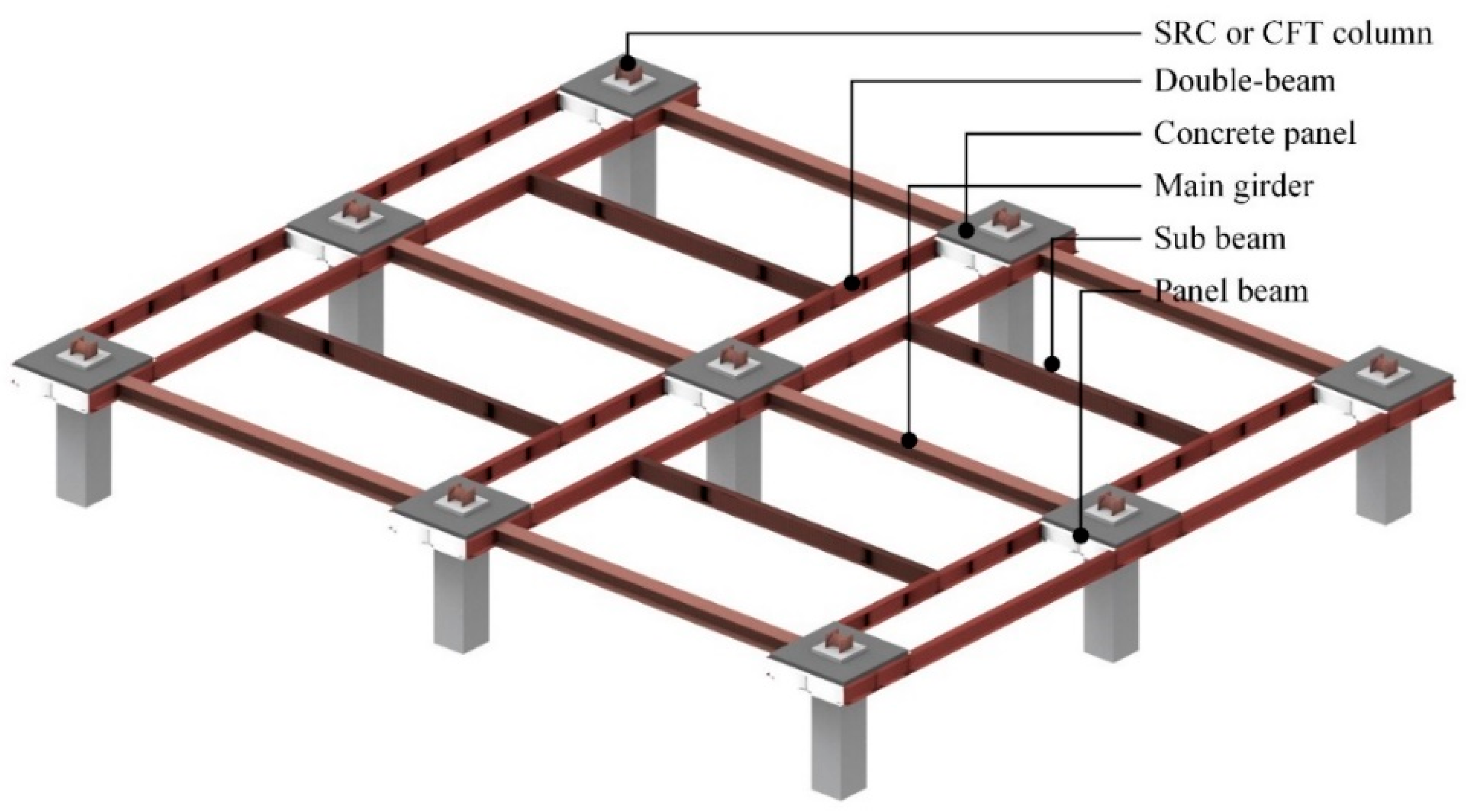
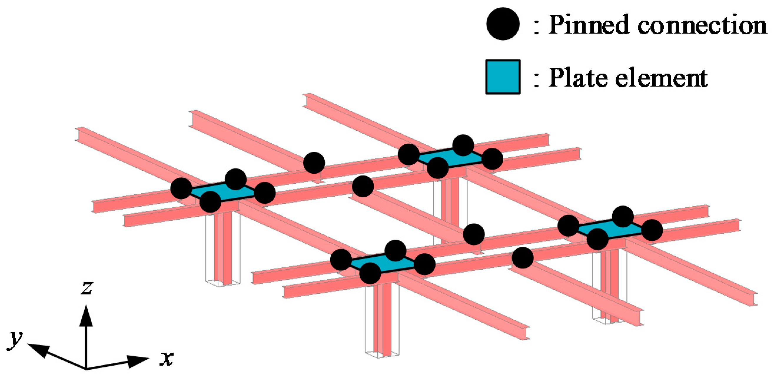
To improve the constructability of the beam–column connection in the steel–concrete composite floor system, we proposed a steel double-beam floor system in previous works [7,19] as shown in Figure 1. The steel double-beam floor system is a composite floor system composed of steel-reinforced concrete (SRC) columns, steel beams, and concrete panels. The steel double-beams are installed in the direction of the short side to distribute the gravity loads. In the steel double-beam floor system, it is possible to reduce the material quantity and improve the environmental performance even under the high gravity load, by introducing the rotational constraint from concrete panels installed at the ends of the double-beam. It is widely known that the constraint effect of concrete in steel–concrete composite joints greatly increases the structural performance of the connection against external loads [20,21]. More reduction of the material quantity is possible if the optimal design is applied to the steel double-beam system. Generally, the optimal design requires iterative analysis taking a lot of time to minimize the objective functions such as cost [22], environmental impact [23], or a combination of both (i.e., multi-objectives) [24,25], while the structural safety is satisfied. Moreover, when design parameters of different structural members have a dependency and they are reflected in the objective functions, the time–cost is increased by the iterative analysis. Since the design parameters of the steel double-beam and the concrete panel have a dependency, in practice, it is challenging to derive optimal design for the steel double-beam floor system using the time-consuming optimal design method with the iterative analysis.
This study aims to develop an optimal design method for the steel double-beam floor system that can simply provide the design parameters without the iterative analysis. A new index, named the LM (Length-Moment) index, regarding the design parameter of steel beam is used to consider both material quantity and structural safety for the design conditions of the underground spaces used as a parking lot. For five live loads taking into account the usage of the underground spaces, the feasibility of the developed design method is verified by comparing it with the material quantity that is designed by the code-based design method. In addition, the structural effect of the rotational constraints from the concrete panel is environmentally quantified by evaluating the global warming potential (GWP) based on the design proposals derived from the proposed design method.
2. Structural Considerations of Steel Double-Beam Floor System
2.1. System Configurations
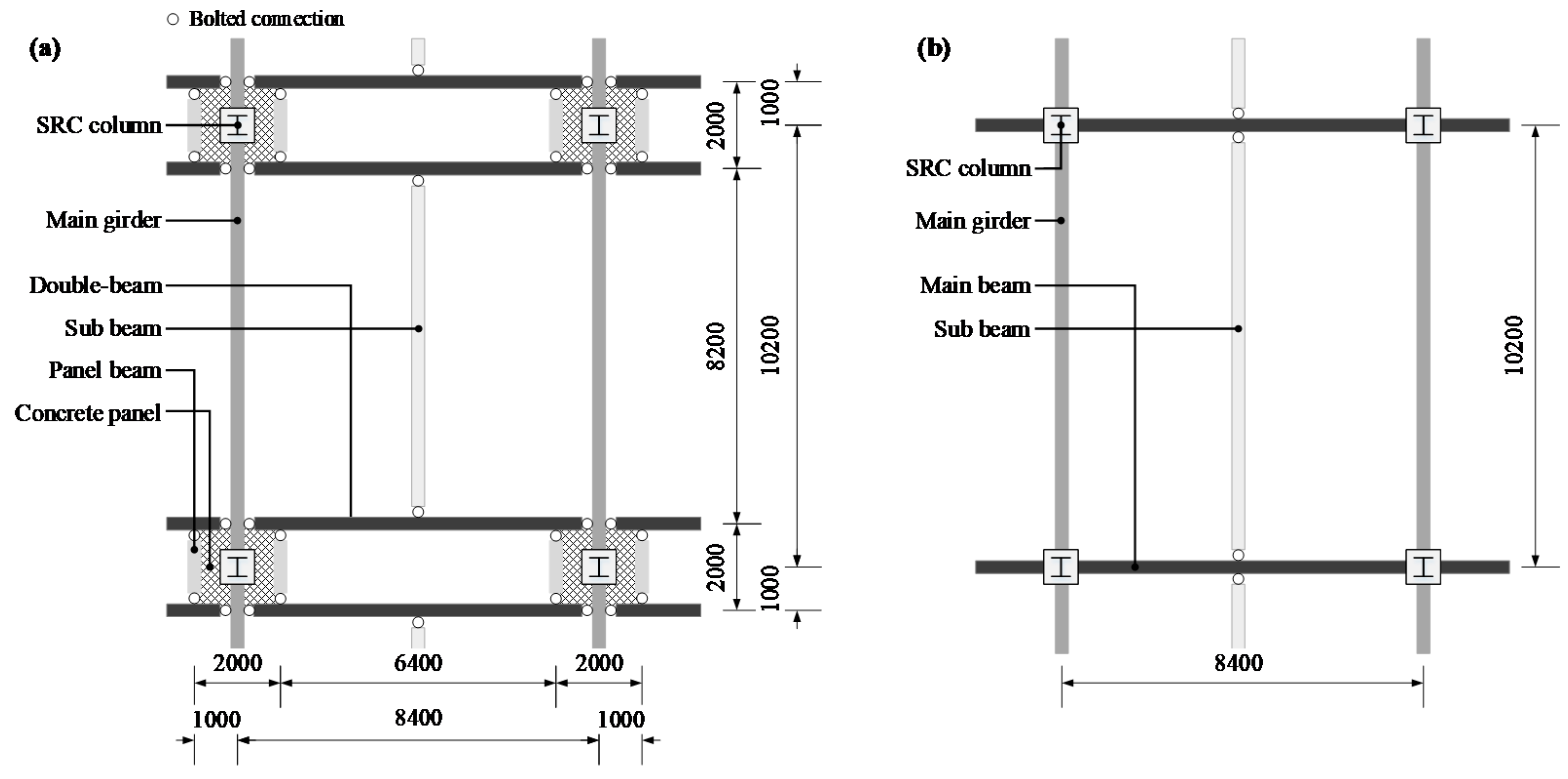
To perform the structural design for the steel double-beam floor systems, the dimension of a building was determined in consideration of usage. According to the Korean Design Standard (KDS) [26], a minimum space of 2.5 × 5.0 m must be required per vehicle. Thus, the dimension of the structural plan was determined as 8.4 × 10.2 m based on the parking space for six vehicles as shown in Figure 2. To investigate the rotational constraints induced by the concrete panels on the environmental impacts, the steel double-beam system was classified into a double-beam floor system with a concrete panel (DBO) and a double-beam floor system without a concrete panel (DBX). By introducing a general beam-girder (GBG) system as a reference system, we evaluated the reduction of the material quantity and the increment of the environmental performance for the steel double-beam systems in the same design conditions. The detailed results of the environmental performance are discussed in Section 4.3.
In the DBX system, the tributary area of the steel double-beam is about half of the main beam in the GBG system, thereby reducing the material quantity of the steel beams. In addition, the bolted connections between the double-beam and the main girder were used to increase in situ constructability. However, since the bolted connections hardly generated a negative moment at the ends of the double-beam, the effect of reduction on the material quantity by applying the DBX system was not significant under the high gravity loads where the live load exceeded 6 kN/m2 [19]. In the DBO system, a positive moment in the center of the double-beam was decreased, as a negative moment was induced at the ends of the double-beam due to the rotational constraints from the concrete panel. Moreover, the positive moment of the double-beam was additionally decreased due to the shortened effective length as much as the width of the concrete panel. Therefore, the DBO system is a more effective structural system in reducing the material quantity than the DBX system under high gravity loads. The effect of rotational constraints on the reduction of the moment demand in the double-beam is discussed in Section 2.2 to consider that in the structural design of the steel double-beam floor system.
2.2. Reduction of Moment Demand in the Double-Beams
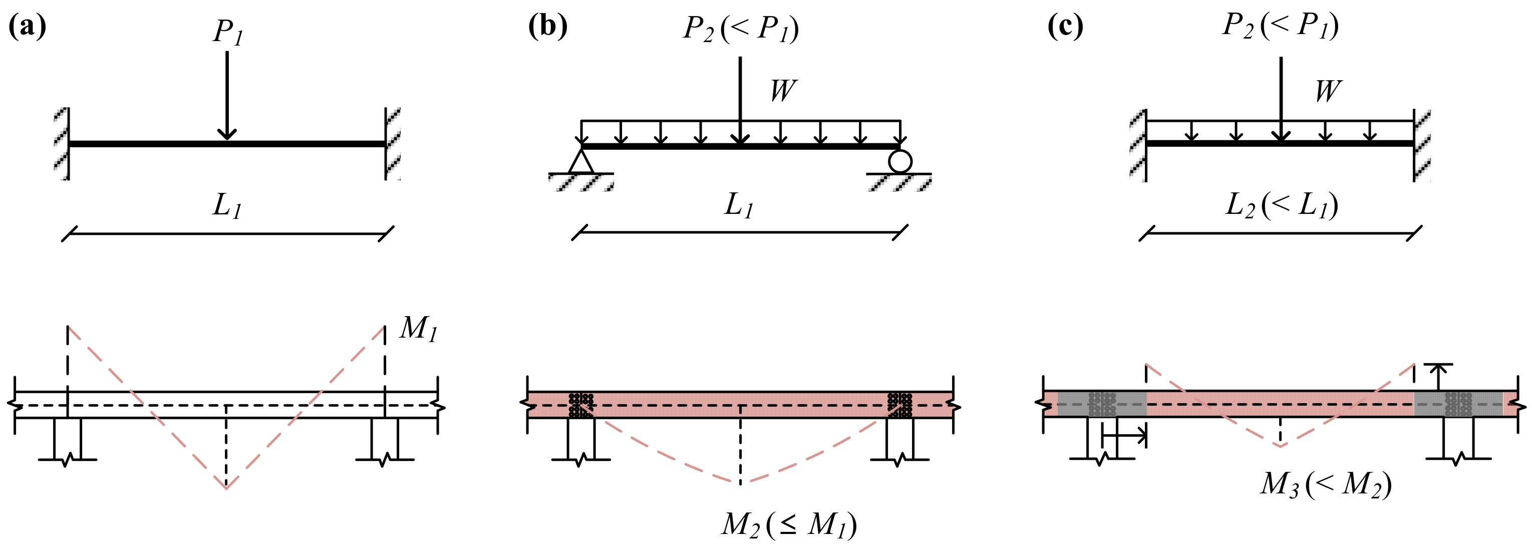
The main beam or double-beam can be idealized according to the boundary conditions and load conditions. As shown in Figure 3a, the main beam of the GBG system can be idealized as a beam that receives a concentrated load in the center with a fixed end condition because the connection of the GBG is designed as an idealized rigid connection. Since the connection of the DBX system is a bolted connection with ideally no rotational constraints at the ends of the double-beam, the double-beam in the DBX system can be thought of as a simply supported beam receiving a uniformly distributed load and a concentrated load, as shown in Figure 3b. The boundary condition at the ends of the double-beam in the DBO system can be idealized as a fixed-end condition if the rotational constraint of the beam-ends is secured large enough. While the load conditions of the double-beam in the DBO and DBX systems are identical, the rotational constraints from the concrete panel can significantly reduce the positive moment demand of the double-beam in the DBO system by generating the negative moment at both ends and shortening the effective length, as shown in Figure 3c. In other words, the addition of concrete panels to the double-beam can realize an economic design of the steel double-beam floor system.
To quantitatively analyze the reduction in the moment demand induced by the rotational constraint, the moment demands by the floor loads were compared between the GBG, DBX, and DBO systems. The moment demand in the main beam of the GBG system for an arbitrary floor load of w (kN/m2) is calculated by Equation (1). The moment demands in the double-beam of DBX and DBO systems are determined using Equations (2) and (3), respectively.
where M1 is the moment demand (kNm) of the main beam in the GBG system, P1 is the concentrated load (kN) acting as the center of the main beam, L1 is the length of the main beam and double-beam (8.4 m), A1 is the tributary area of the main beam, which is (10.2 m × (8.4 m/2))/2 × 2EA = 42.84 m2, w is the arbitrary floor load (kN/m2), M2 is the moment demand (kNm) of the double-beam in the DBX system, P2 is the concentrated load (kN) acting as the center of double-beam, W1 is the uniformly distributed load (kN/m) from the slab, A2 is the tributary area of the double-beam, which is (8.2 m × (8.4 m/2))/2 × 1EA = 17.22 m2, Dc is the half-width of the concrete panel, which is 1.0 m, M3 is the moment demand (kNm) of the double-beam in the DBO system, and L2 is the effective length of double-beam in DBO system (6.4 m).
The maximum moment in the main beam and double beam of GBG, DBX, and DBO systems was calculated as 45.0, 45.0, and 17.2 w using Equations (1)–(3). Therefore, the rotational constraint from the concrete panel in ideal conditions can reduce the moment demand of the double-beam in the DBO system to a maximum of about 38.2% compared to the moment demand of the main beam in the GBG system.
2.3. Rotational Constraints Induced by Concrete Panel
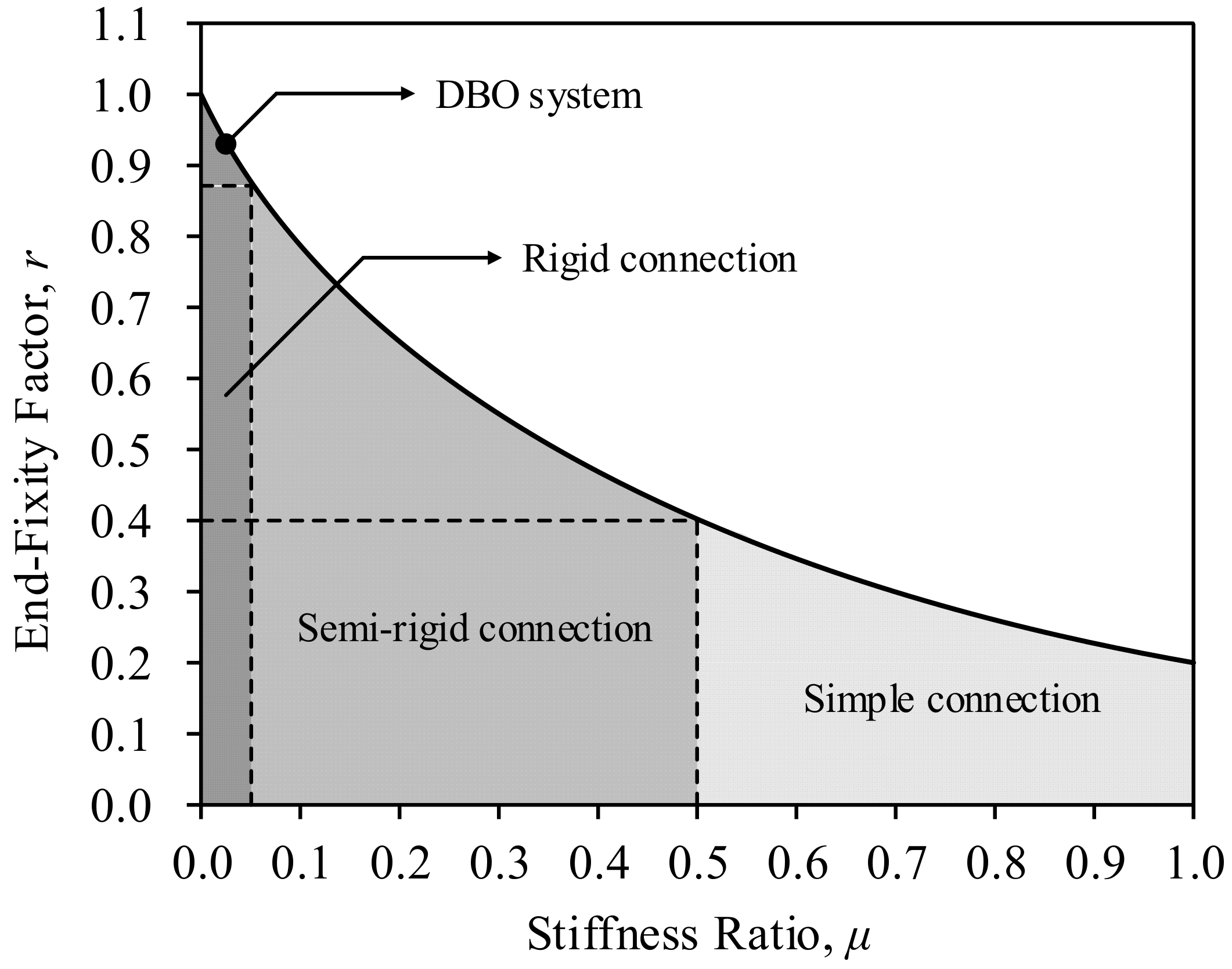
For the structural design of the DBO system, as the rotational constraint induced by the concrete panel has a great influence on the moment demand of the double-beam, it is necessary to reflect the actual rotational constraint evaluated considering the practical boundary conditions rather than the idealized boundary conditions. Figure 4 shows the relationship between the stiffness ratio (μ), defined as the ratio of the rotational stiffness of the connection (KR) to the flexural stiffness of the double-beam (KF), and the end-fixity factor (r), defined as the fixed end moment to the negative moment generated at the connection. From the experimental study for the steel double-beam floor system [7], the connection comprised of the steel double-beam and the concrete panel corresponding to the connection of the DBO system represents a rotational constraint equivalent to a code conforming rigid connection suggested by ANSI/AISC 360 (American National Standards Institute/American Institute of Steel Construction) [27], as shown in Figure 4. Thus, the connection of the DBO system can be modeled as a rigid connection in the structural analysis based on the experimental result.
2.4. Design Parameters of Steel Double-Beam Floor System with Concrete Panel
This study aimed to develop the optimal design method for the steel double-beam floor system considering the rotational constraint of the concrete panel without the iterative analysis. To secure the rotational constraints equivalent to the rigid connection, the value of stiffness ratio should be less than 0.05 as shown in Figure 4. In previous work [7], the flexural behavior of the double-beam floor system was experimentally evaluated according to the presence of the concrete panel, and the stiffness ratio of the composite connection was determined to 0.032 (see [7] for the detailed information about the stiffness ratio). In addition, as the stiffness ratio is independent of the boundary conditions, in this study, the stiffness ratio of the composite connection in the DBO system was fixed at 0.032 based on the previous work [7].
The stiffness ratio of the connection is defined as Equation (4). As shown in Figure 5, the connections between the double-beam and main beam were modeled as an idealized pinned connection without the rotational constraints; that is, the rotational stiffness of the connections (KR) was generated by the flexural stiffness of the concrete panel (KP), which is defined by Equation (5) according to the Kirchhoff–Love plate theory.
where μ is the stiffness ratio of the connection (0.032 for the DBO system), KF is the flexural stiffness of the double-beam, KR is the rotational stiffness of the connection, E is the elastic modulus of the double-beam (205,000 MPa), I is the moment of inertia of the double-beam (m4), and L is the length of the double-beam (m).
Since KR and KP are equal, by substituting KP in Equation (5) for KR in Equation (4), the thickness of the concrete panel is calculated as Equation (6). The reinforcement of the concrete panel was designed to meet the minimum ratio of 0.0018, suggested by ACI 318-19 (American Concrete Institute) [28], for preventing cracks due to shrinkage and temperature. Since the reinforcement of the concrete panel has little effect on the flexural stiffness of the concrete panel, the flexural stiffness of the concrete panel was determined considering only the concrete material. The design parameter of the concrete panel considered in this study was the thickness of the concrete panel (TP), and the design parameters of the double-beam affecting the thickness were the moment of inertia (I) and the length (L). Generally, the length of the beam elements is determined by the distance between columns according to the usage of buildings, so the remaining design parameters in the connection are the thickness of the concrete panel and the moment of inertia of the double-beam. These two design parameters have a dependency as summarized in Equation (6). The variation in the cross-section of the double-beam for quantity optimization leads to a change in the thickness of the concrete panel, and the changed thickness affects the rotational constraint of the connection. In other words, the dependency in the two design parameters of the connections causes the time-consuming iterative analysis in the quantity optimization process as the rotational constraint of the connection modified the moment demand of the double-beam related to the safety. To optimize the material quantity for the steel double-beam floor system in practice, a new optimal design method that can reflect the effect of rotational constraint without the iterative analysis is needed, and details are dealt with in Section 3.
where KP is the flexural stiffness of the concrete panel (kNm/rad), EP is the elastic modulus of the concrete panel (MPa), TP is the thickness of the concrete panel (mm), and v is the Poisson’s ratio of concrete (0.15).
3. Optimal Design Method Using LM Index
To derive an optimal design for a structural system, all design parameters including the material strengths are considered in the optimization process. However, in this study, the yield strength of steel and the compressive strength of concrete were fixed to 325 and 27 MPa, respectively, to reflect the design conditions of the steel double-beam floor systems in practice. With the optimization process in the material quantity of the steel-double-beam floor system using a code-based design method, the dependency of the design parameters between the concrete panel and the double-beam accompanies many iterations of structural analysis. In this section, a new optimal design method for the steel double-beam floor systems is presented to improve the iterative process in the code-based design method.
3.1. Objective Function
In the steel double-beam floor system with the concrete panel, the material quantity of structural members is determined by the weight of steel and concrete. While there is some contribution of the concrete panel to the total material quantity, the environmental contribution of the concrete panel based on GWP is very low, about 10% of the total [19]. In addition, when a quantity-optimized cross-section of the double-beam is determined, the thickness of the concrete panel related to the material quantity of concrete is calculated from Equation (6). The objective function for minimizing the material quantity of the steel double-beam floor system can be defined as Equation (7), considering only the weight of steel beam members. Therefore, the cross-sectional area of the steel beams was chosen as the design variable in the material quantity optimization because the cross-sectional area of the H-beam was linearly proportional to the weight [29].
where W is the objective function of the material quantity expressed in weight (kN), ρs is the density of the steel (78.5 kN/m3), Ais is the cross-sectional area of the i-th steel beam, Lis is the length of the i-th steel beam, and M is the total number of the steel beam.
3.2. Constraints Conditions
The deflection and strength conditions for steel beams are employed as the safety-related constraint condition, as shown in Equations (8) and (9). The deflection limit of the steel beam shall not exceed LS/480 in accordance with ASCE 7-16 (American Society of Civil Engineers) [30] under the service load (i.e., 1.0 D.L + 1.0 L.L). The moment demand is calculated under the factored load about the gravity loads (i.e., 1.2 D.L + 1.6 L.L), and the nominal flexural strength of the steel beam is determined by considering the unbraced length (Lb) according to ANSI/AISC 360-16 [27].
where δiSL is the maximum deflection of the i-th steel member under the service load, Miu is the design moment (i.e., moment demand) of the i-th steel beam (kNm), ϕb is the flexural strength reduction factor (0.9), and Min is the nominal flexural strength of the i-th steel beam.
3.3. Formulation of Optimization Problem Using LM Index
In the optimization process of the material quantity, the cross-sectional areas of the steel beam are obtained through iterative analysis to minimize the objective function under the safety-related constraint conditions. In the GBG system, since the connections between the main beam and girder are modeled as an ideal pinned or rigid connection, the changes in the steel members do not affect the connection modeling. In the DBO system, however, the changes in the sectional properties of the steel double-beam cause the modification in the thickness of the concrete panel. In this study, by modifying the objective function shown in Equation (7), an optimal design method for the DBO system was developed without iterative analysis.
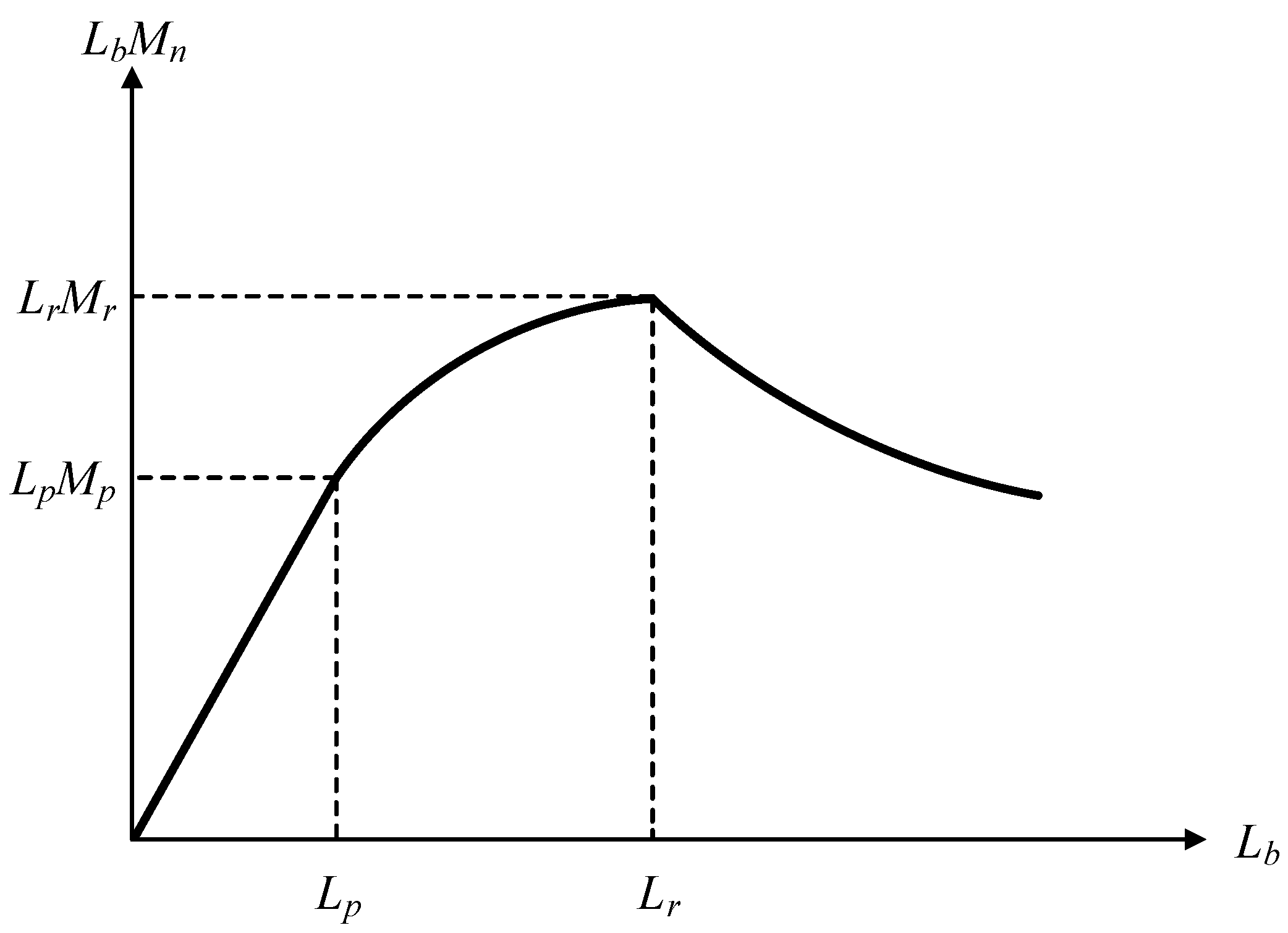
By multiplying the unbraced length of each member (Lib) to the denominator and numerator on the left side of Equation (9), Equation (10) is yielded. Herein, LbMn is named as the LM index. Figure 6 shows the LM index for hot-rolled H-beam according to the unbraced length. Since the LM index has a unique characteristic of having a maximum value in Lr, it can be defined as an index representing the properties of the H-beam. Using this unique characteristic, the LM index in terms of capacity (LMC) is defined as Equation (11). The LM index in terms of demand (LMD) is defined as Equation (12).
where Lib is the unbraced length of the steel beams (m), Lir is the limiting laterally unbraced length for the limit state of inelastic lateral–torsional buckling (m), Mir is the inelastic bending moment for lateral–torsional buckling (kNm), LMiC is the LM index in terms of capacity (kNm2), and LMiD is the LM index in terms of demand (kNm2). The superscript i denotes i-th steel member.
In KS D 3502 (Korean Industrial Standards) [31], the sectional information, such as unit weight, cross-sectional area, and moment of inertia so on, is presented for 95 H-beams. Figure 7 shows the unit weight for 95 H-beams suggested in KS D 3502 in accordance with the cross-sectional area and the LM index in terms of capacity (LMC). Since LMC is defined as the product of Lr and Mr as shown in Equation (11), Lr and Mr are calculated from the cross-sectional information of KS D 3502 to derive LMC for 95 H-beams. As shown in Figure 7a, the cross-sectional area of the H-beam shows a linear proportional relationship to the weight, so it is suitable as an objective function for optimizing the weight. Since the relationship between the LMC and the weight presents a proportional relation as shown in Figure 7b, the values of LMC can be considered as a weight. If the difference between LMC and LMD is minimized, it is possible to minimize weight as a result. Therefore, the objective function for minimizing material quantity using the LM index as a design variable can be defined as Equation (13).
where WLM is the objective function of the material quantity expressed in the LM index (kNm2).
The constraint conditions used in the proposed optimal design method using the LM index are expressed as Equations (14) and (15). In the case of optimization using only the LM index, an increment in the unbraced length leads to a decrement in the nominal flexural strength, so the safety-related design condition may not be satisfied. Equation (14) is employed as a safety-related constraint condition in the proposed optimal design method to prevent violation of the design condition. Equation (15) is a constraint condition for selecting an H-beam with LMC larger than LMD.
where Mip is the plastic bending moment (kNm).
3.4. Optimal Design Process Using LM Index
Figure 8a shows the optimization process using a code-based design method. After calculating the moment demand by structural analysis for the initial design conditions, the objective function is calculated from the cross-sectional area of the designed H-beams if the constraints for Equations (8) and (9) are satisfied. If the constraints are not satisfied, the steel beams are redesigned, which leads to the redesign of the concrete panel. On the other hand, as summarized in Figure 8b, the proposed optimal design method does not require an iterative process in quantity optimization. After deriving the H-beams satisfying the constraint conditions for Equations (14) and (15), the sections of the H-beam minimizing the objective function in Equation (13) can be directly selected without repetition. Finally, the optimization process is simply completed by calculating the thickness of the concrete panel based on the moment of inertia of designed H-beams.
4. Application to Steel Buildings in Downtown Area
4.1. Frame Analysis According to Levels of Gravity Load
The feasibility of implementing the proposed optimal design method using the LM index was investigated through the quantity-optimized design of the underground structure of the steel buildings under various gravity loads. The dead load was 5.2 kN/m2 including the slab thickness and the floor finishing. The live load was divided into five categories considering the usage of the underground space in the downtown area: 2.5, 4.0, 6.0, 8.0, and 12.0 kN/m2 (see previous work [19] for detailed information about the live loads). The dimensions of the structural plan for the steel double-beam floor systems were summarized in Figure 2, and MIDAS-Gen [32], a commercial structure analysis program, was used for frame analysis. In addition, to examine the reduction of material quantity and the improvement of the environmental performance of the DBO system, the quantity-optimizations for the GBG and DBX systems were performed using the proposed optimal design method under the same design conditions.
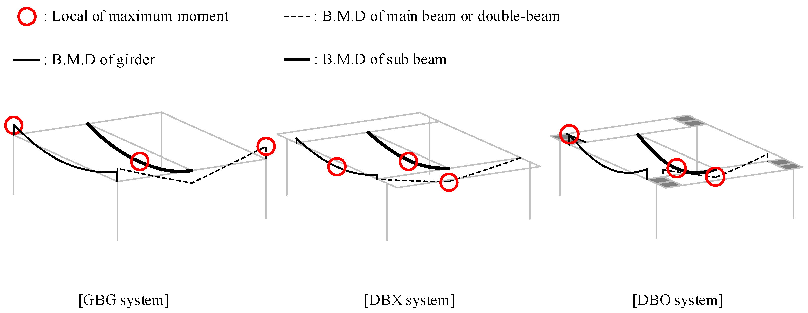
Figure 9 shows the moment diagram of the structural members in each structural system with the locations of the maximum moment (Mu). Depending on the load and boundary conditions of the structural members, the locations of the maximum moment were varied. From the results of the frame analysis for each structural system, the Mu, used as demand in the code-based design, and the LMD, used as demand in the proposed optimal design, are summarized in Table 1.
In the code-based design, if the initially assumed cross-section of the H-beam does not satisfy the safety-related constraints, the cross-section of the H-beam must be changed because the constraints are mandatory in structural design. On the other hand, the proposed design method can directly select a cross-section of the H-beam with LMC that minimizes the difference from the LMD summarized in Table 1. For example, the LMD of the double-beam in a DBO system with a live load of 8 kN/m2 is 1075.8 kNm2. In this condition, a cross-section of H-400x200x8x13 having the LMC of 1233.7 kNm2 is simply selected without iteration because it has the minimum LMC that satisfies the objective function. In addition, the ϕbMn of the selected double-beam (356.3 kNm) exceeds the Mu (336.2 kNm), so it can be seen that the cross-section selected by the LM index also meets the safety-related constraint in this case.
4.2. Verification of Proposed Optimal Design Method
Based on the results of frame analysis in Section 4.1, the design proposal derived by the code-based method and the proposed method for the DBO system, subjected to 8 kN/m2 of live load, is summarized in Table 2. The cross-sections of all members designed by the two methods were equal, and the thickness of the concrete panel by them also equal due to the dependency of design parameters between the double-beam and concrete panel. Thus, the proposed optimal design method using the LM index can optimize the material quantity while avoiding the iterative process. To further investigate the feasibility of the proposed optimal design method in the quantity-optimization, the cross-sections designed by the two methods were compared for the five levels of live load.
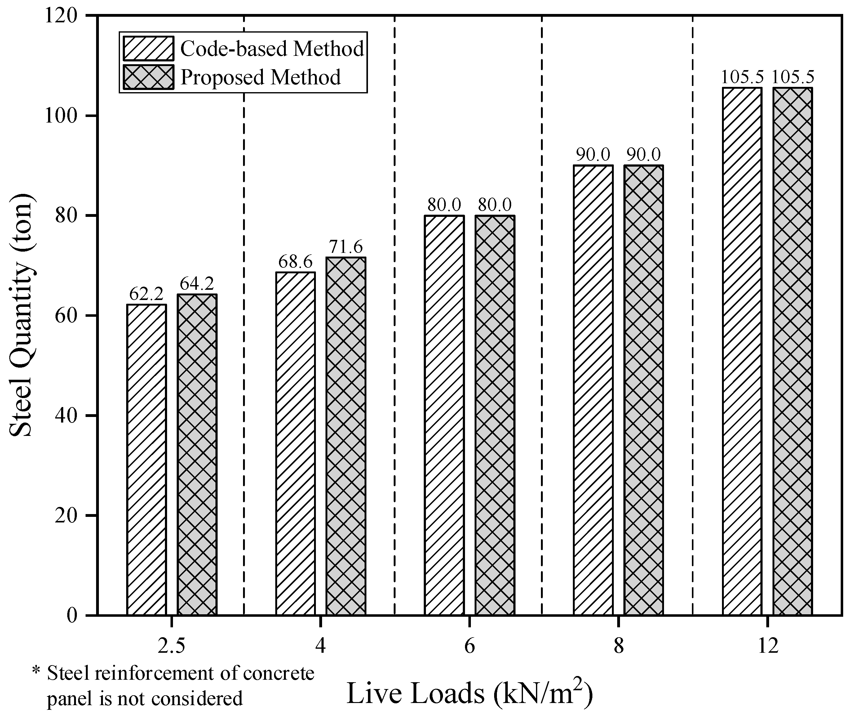
Figure 10 shows the comparison of the total material quantity of steel members designed by the code-based method and the proposed method according to the level of live load considered for the DBO system. Overall, the material quantities derived by the two design methods were similar. In particular, when the live load was lower than 4.0 kN/m2, the design proposal derived by the proposed method showed higher material quantity than that of the code-based method. At relatively low live loads, since the Mn of the H-beam optimized by the LM index tended to be slightly larger than Mu, the design proposal by the proposed optimal design method was analyzed to evaluate the material quantity somewhat higher than the code-based method. This is because the Lr of the optimized section at low live loads was shorter than that of the Lb, so that the section, satisfying the safety-related constraint conditions of the code-based method, did not satisfy the safety-related constraint conditions of the proposed method. For live loads of 6, 8, and 12.0 kN/m2, the material quantities derived by the two design methods were equal to 80.0, 90.0, and 105.5 ton, respectively. Therefore, the proposed design method yielded a quantity-optimized design proposal similar to the code-based method while avoiding a time-consuming iterative process.
The proposed optimal design method using the LM index was developed to improve the iterative process caused by the dependency between the design parameters of concrete panels and double beams in a steel double-beam floor system. As a result of quantity optimization for the GBG system and DBX system by using the proposed design method, the proposed design method was able to optimize the material quantity similar to the code-based design method for these two systems. Regardless of the structural systems, the reason why reliable material quantity optimization is possible through the proposed method is that the range of the Lr (5.2~7.9 m) in the selected section and the range of Lb (6.4~8.2 m) in the structural plan are similar. If Lr and Lb are the same, a selected cross-section of H-beam through the LM index can derive a design proposal with the smallest material quantity while satisfying safety. Thus, the proposed optimal design method can be used as an alternative for material quantity optimization if the structural plan used in this study represents a typical steel building located downtown.
4.3. Effect of Rotational Constraints in Environmental Performance
From an environmental point of view, while the contribution of the concrete panel to embodied CO2 emissions is very low, the rotation constraints from the concrete panel can greatly improve the overall environmental performance of the double-beam floor system by reducing the material quantity. To evaluate the environmental performance according to the presence or absence of concrete panels, the global warming potential (GWP) was calculated through Equation (16) from the quantity of steel and concrete derived by the proposed optimal design method. In the DBO system, the concrete quantity of the concrete panel was considered to calculate the GWP.
where CO2, Embodied represents the embodied CO2 emission of whole building materials (see detailed calculation process in [19]) and CF is the characterization factor for the GWP (1.00 kgCO2-eq/kg from IPCC 2013 [33]).
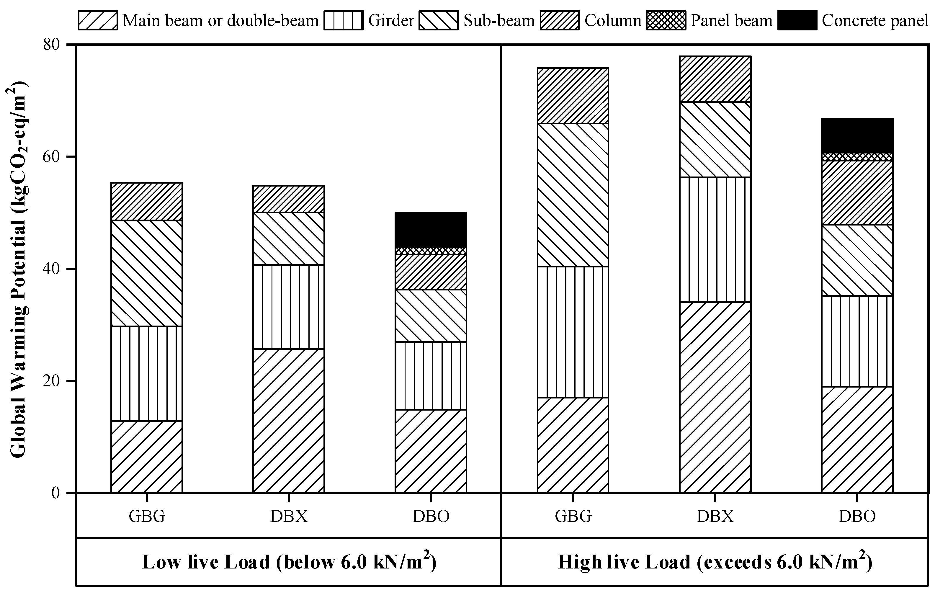
Figure 11 shows the comparison of GWP normalized to the floor area at low live load (below 6.0 kN/m2) and high live load (exceed 6.0 kN/m2) for each structural system. While the DBX system had a slightly smaller GWP value than the GBG system due to the decrease in the material quantity of sub-beams at low live load, the GWP value of the DBX system increased more than the GBG due to the increase in the material quantity of double beams at high live load. The DBO system exhibited the smallest GWP value compared to the other two structural systems at all live loads. The reason that the GWP value of the DBO system was the smallest is that the rotational constraint induced by the concrete panel greatly influenced the reduction of GWP value in the double-beam. The structural characteristic such as the rotational constraint could improve environmental performance, and the GWP value of the DBO system was 13.1% smaller than the GWP value of the GBG system at high live loads. In other words, the steel double-beam floor system improves environmental performance by adding concrete panels to buildings that require a high live load. In addition, the proposed optimal design method can be effectively used in the optimization process of the material quantity requiring for evaluation in environmental performance.
5. Conclusions
In the steel double-beam floor system, the concrete panel should have an appropriate thickness to induce the rotational constraints required for a code-conforming rigid connection in the ends of the double-beam. However, the dependency of design parameters between the concrete panel and the double-beam caused time-consuming iterative analysis in the quantity optimization process. In this study, an optimal design method was developed to solve the iterative design problem of steel double-beam floor systems considering the beam-end constraints induced by the concrete panels. The LM index multiplied by the length and moment of structural members was employed as a design variable to consider both safety and material quantity. A series of structural analyses for the steel double-beam floor systems was performed to calculate the moment demand varying the live loads in consideration of the usage of underground space. The beam sections designed from the developed method were verified through comparison with the design results of the code-based design method requiring iterative analysis. In addition, the effect of rotational constraints caused by the concrete panels was quantitatively evaluated in terms of the environmental point of view. The conclusions that were obtained through this study are as follows:
- The LM index in terms of capacity (LMC) was defined as the product of unbraced length (Lb) and nominal flexural strength (Mn) of the steel beam, and LMC had an intrinsic characteristic of having a maximum value in the limiting unbraced length for inelastic lateral–torsional buckling (Lr). Since the value of LMC is proportional to the material quantity, it was used as a design variable for quantity optimization instead of cross-sectional area;
- The steel beam sections selected by the LM index satisfied the safety-related constraint conditions. As the LM index reflected the flexural strength considering the lateral torsional-buckling according to the Lb, a cross-section with an LM index that minimizes the objective function automatically met the safety-related constraint conditions if the Lr and Lb were similar. For the steel double-beam floor system with the concrete panel (DBO system), the design results using the LM index showed that the range of the Lr (5.9~7.9 m) for the designed H-beam sections was similar to the range of the Lb (6.4~8.2 m) determined by the structural plan. Therefore, the developed design method could provide the optimal design proposals with securing structural safety for the DBO system;
- Under the low gravity loads with a live load of 4 kN/m2 or less, the design proposal derived by the developed method showed a higher material quantity of 2.0 ton compared to that of the code-based method. Since the Mn of the designed sections as the LM index tended to be larger than the Mu, the developed method evaluated the slightly higher material quantity than that of the code-based method under the low gravity load. On the other hand, for the high gravity load with a live load of 6.0 kN/m2 or more, the material quantities derived by the developed and code-based methods were equal. At the high gravity loads, as the Mu increased, the difference in Mn of the designed section using the LM index decreased, so the developed method suggested the same optimal design proposal as the code-based method. Therefore, the developed design method provided a more optimal design option under the high gravity loads;
- The steel double-beam floor system without concrete panel (DBX system) had a higher global warming potential (GWP) than the general beam-girder system (GBG system) at high gravity loads where the live loads exceeded 6.0 kN/m2. On the other hand, the addition of the concrete panels significantly contributed to the improvement of the environmental performance in the steel double-beam floor system by reducing the GWP up to 13.1% compared to the GBG system under the high gravity loads.
The developed optimal design method using the LM index can optimize the material quantity of the steel double-beam floor systems while satisfying the safety without iterative analysis. In addition, since the feasibility of the developed optimal design method has been verified for the general steel frames, it can be an alternative to the code-based design method.
Author Contributions
Conceptualization, I.C. and J.K.; formal analysis, I.C. and D.K.; funding acquisition, J.K.; methodology, I.C., D.K., and J.K.; project administration, J.K.; investigation, I.C. and D.K.; software, I.C. and D.K.; supervision, J.K.; validation, I.C., D.K., and J.K.; visualization, I.C., D.K., and J.K.; writing—original draft, I.C.; writing—review and editing, I.C., D.K., and J.K. All authors have read and agreed to the published version of the manuscript.
Funding
This research was supported by a grant (NRF-2021R1A2C2007064) from the National Research Foundation of Korea (NRF) funded by the Korean Ministry of Science and ICT (MSIT) and by the Graduate School of YONSEI University Research Scholarship Grants in 2020.
Institutional Review Board Statement
Not applicable.
Informed Consent Statement
Not applicable.
Data Availability Statement
The data presented in this study are available on request from the corresponding author.
Conflicts of Interest
The authors declare no conflict of interest.
References
- Rhim, H.-C.; Kim, K.-M.; Kim, S.-W. Development of an optimum pre-founded column system for top-down construction. J. Civ. Eng. Manag. 2012, 18, 735–743. [Google Scholar] [CrossRef] [Green Version]
- Kim, D.; Jeong, S.; Jung, G.; Park, J. Load-sharing ratio of prebored and precast pile in top-down method construction process. Struct. Des. Tall Spec. Build. 2018, 27, 1472. [Google Scholar] [CrossRef]
- Fang, G.X.; Jin, Z.C. A study of the planning methods in the underground work of top-down construction in high-rise buildings. In Advanced Materials Research; Trans Tech Publications Ltd.: Kapellweg, Switzerland, 2014; Volume 1044–1045, pp. 561–565. [Google Scholar]
- IEA. CO2 Emissions from Fuel Combustion; International Energy Agency: Paris, France, 2019. [Google Scholar]
- Dimoudi, A.; Tompa, C. Energy and environmental indicators related to construction of office buildings. Resour. Conserv. Recycl. 2008, 53, 86–95. [Google Scholar] [CrossRef]
- Brambilla, G.; Lavagna, M.; Vasdravellis, G.; Castiglioni, C.A. Environmental benefits arising from demountable steel-concrete composite floor systems in buildings. Resour. Conserv. Recycl. 2019, 141, 133–142. [Google Scholar] [CrossRef]
- Choi, I.; Kim, J.H.; Jang, J.; Chang, H.; Kang, G. Composite effects on rotational constraints of a double-beam system reinforced with beam-end concrete. Eng. Struct. 2021, 228, 111585. [Google Scholar] [CrossRef]
- Nie, J.; Wang, J.; Gou, S.; Zhu, Y.; Fan, J. Technological development and engineering applications of novel steel-concrete composite structures. Front. Struct. Civ. Eng. 2019, 13, 1–14. [Google Scholar] [CrossRef]
- Choi, I.; Kim, J.H.; Kim, H.-R. Composite Behavior of Insulated Concrete Sandwich Wall Panels Subjected to Wind Pressure and Suction. Materials 2015, 8, 1264–1282. [Google Scholar] [CrossRef] [PubMed] [Green Version]
- Choi, I.; Kim, J.H.; You, Y.-C. Effect of cyclic loading on composite behavior of insulated concrete sandwich wall panels with GFRP shear connectors. Compos. Part B Eng. 2016, 96, 7–19. [Google Scholar] [CrossRef]
- Li, C.; Li, G.; Yu, R.; Ma, X.; Qin, P.; Wang, X. Study on Mechanical Properties of Multi-Cavity Steel–Concrete Composite Floor. Appl. Sci. 2020, 10, 8444. [Google Scholar] [CrossRef]
- Mullett, D.L. Composite Floor Systems; The Steel Construction Institute, Blackwell Science: Oxford, UK, 1998. [Google Scholar]
- Naccarato, P.A. Modern Steel Construction; American Institute of Steel Construction: Chicago, IL, USA, 2000. [Google Scholar]
- Ju, Y.K.; Kim, J.-Y.; Kim, S.-D. Experimental Evaluation of New Concrete Encased Steel Composite Beam to Steel Column Joint. J. Struct. Eng. 2007, 133, 519–529. [Google Scholar] [CrossRef]
- Park, H.-G.; Hwang, H.-J.; Lee, C.-H.; Park, C.-H.; Lee, C.-N. Cyclic loading test for concrete-filled U-shaped steel beam-RC column connections. Eng. Struct. 2012, 36, 325–336. [Google Scholar] [CrossRef]
- Hwang, H.-J.; Eom, T.-S.; Park, H.-G.; Asce, A.M.; Lee, S.-H.; Kim, H.-S. Cyclic Loading Test for Beam-Column Connections of Concrete-Filled U-Shaped Steel Beams and Concrete-Encased Steel Angle Columns. J. Struct. Eng. 2015, 141, 4015020. [Google Scholar] [CrossRef] [Green Version]
- Amadio, C.; Macorini, L.; Sorgon, S.; Suraci, G. A novel hybrid system with rc-encased steel joists. Eur. J. Environ. Civ. Eng. 2011, 15, 1433–1463. [Google Scholar] [CrossRef]
- Lee, J.-M.; Kim, M.-J.; Lee, Y.-J.; Kim, S.-W.; Lee, J.-Y.; Kim, K.-H. Structural performance of composite double beam system. Adv. Struct. Eng. 2016, 19, 283–298. [Google Scholar] [CrossRef]
- Choi, I.; Kim, J.; Kim, D. LCA-Based Investigation of Environmental Impacts for Novel Double-Beam Floor System Subjected to High Gravity Loads. Sustainability 2020, 12, 9193. [Google Scholar] [CrossRef]
- Tan, Y.; Zhu, B.; Yan, T.; Huang, B.; Wang, X.; Yang, W.; Huang, B. Experimental Study of the Mechanical Behavior of the Steel–Concrete Joints in a Composite Truss Bridge. Appl. Sci. 2019, 9, 854. [Google Scholar] [CrossRef]
- Dung Le, D.; Nguyen, X.-H.; Nguyen, Q.-H. Cyclic Testing of a Composite Joint between a Reinforced Concrete Column and a Steel Beam. Appl. Sci. 2020, 10, 2385. [Google Scholar] [CrossRef] [Green Version]
- Congedo, P.M.; Baglivo, C.; D’Agostino, D.; Zacà, I. Cost-optimal design for nearly zero energy office buildings located in warm climates. Energy 2015, 91, 967–982. [Google Scholar] [CrossRef]
- Kaveh, A.; Izadifard, R.A.; Mottaghi, L. Optimal design of planar RC frames considering CO2 emissions using ECBO, EVPS and PSO metaheuristic algorithms. J. Build. Eng. 2020, 28, 101014. [Google Scholar] [CrossRef]
- Lee, M.G.; An, J.H.; Bae, S.G.; Oh, H.S.; Choi, J.; Yun, D.Y.; Hong, T.; Lee, D.-E.; Park, H.S. Multi-objective sustainable design model for integrating CO 2 emissions and costs for slabs in office buildings. Struct. Infrastruct. Eng. 2020, 16, 1096–1105. [Google Scholar] [CrossRef]
- Yepes, V.; Dasí-Gil, M.; Martínez-Muñoz, D.; López-Desfilis, V.J.; Martí, J.V. Heuristic Techniques for the Design of Steel-Concrete Composite Pedestrian Bridges. Appl. Sci. 2019, 9, 3253. [Google Scholar] [CrossRef] [Green Version]
- MOLIT. Korean Design Standard (in Korean); Ministry of Land, Infrastructure and Transport: Sejong City, Korea, 2016.
- AISC Committee. Specification for Structural Steel Buildings (ANSI/AISC 360-16); AISC Committee: Chicago, IL, USA, 2016. [Google Scholar]
- ACI Committee. Building Code Requirements for Structural Concrete and Commentary (ACI 318-19); ACI Committee: Farmington Hills, MI, USA, 2019. [Google Scholar]
- Camp, C.V.; Bichon, B.J.; Stovall, S.P. Design of Steel Frames Using Ant Colony Optimization. J. Struct. Eng. 2005, 131, 369–379. [Google Scholar] [CrossRef]
- ASCE ASCE/SEI 7-16. Minimum Design Loads for Buildings and Other Structures; American Society of Civil Engineers: Reston, VA, USA, 2016. [Google Scholar]
- Korean Standard Association KS D 3502:2021. Dimensions, Mass and Permissible Variations of Hot Rolled Steel Sections; KATS: Eumseong-gun, Korea, 2021.
- MIDAS IT. MIDAS/GEN V8.5.5 Users Manual; MIDAS IT: Seongnam-si, Korea, 2017. [Google Scholar]
- Myhre, G.; Shindell, D.; Bréon, F.M.; Collins, W.; Fuglestvedt, J.; Huang, J.; Koch, D.; Lamarque, J.F.; Lee, D.; Mendoza, B. Anthropogenic and Natural Radiative Forcing. In Climate Change 2013: The Physical Science Basis; Contribution of Working Group I to the Fifth Assessment Report of the Intergovernmental Panel on Climate Change; Cambridge University Press: Cambridge, UK, 2013; pp. 659–740. [Google Scholar]
Figure 1.
Structural configurations of steel double-beam floor system with the concrete panel.

Figure 2.
Structural plan for an underground space of buildings used for parking lots according to the applied structural systems: (a) Steel double-beam floor system with concrete panel (DBO system) and (b) general beam-girder system (GBG system).
Figure 2.
Structural plan for an underground space of buildings used for parking lots according to the applied structural systems: (a) Steel double-beam floor system with concrete panel (DBO system) and (b) general beam-girder system (GBG system).

Figure 3.
Idealized moment diagram induced by one-way gravity load: (a) Main beam in GBG system, (b) steel double-beam in double-beam floor system without a concrete panel (DBX) system, and (c) steel double-beam in DBO system.
Figure 3.
Idealized moment diagram induced by one-way gravity load: (a) Main beam in GBG system, (b) steel double-beam in double-beam floor system without a concrete panel (DBX) system, and (c) steel double-beam in DBO system.

Figure 4.
Relationship between rotational stiffness (stiffness ratio, μ) and negative moment (end-fixity factor, r) in double-beam floor system with the connection type suggested by ANSI/AISC 360 (American National Standards Institute/American Institute of Steel Construction) [27].
Figure 4.
Relationship between rotational stiffness (stiffness ratio, μ) and negative moment (end-fixity factor, r) in double-beam floor system with the connection type suggested by ANSI/AISC 360 (American National Standards Institute/American Institute of Steel Construction) [27].

Figure 5.
Connection modeling of the steel double-beam floor system with the concrete panel.

Figure 6.
Relationship between unbraced length (Lb) and LM index (LbMn) in hot-rolled H-beam.

Figure 7.
Unit weight of hot-rolled H-beam: (a) Cross-sectional area vs. unit weight and (b) capacity of LM index vs. unit weight.
Figure 7.
Unit weight of hot-rolled H-beam: (a) Cross-sectional area vs. unit weight and (b) capacity of LM index vs. unit weight.

Figure 8.
Optimization process in code-based design and proposed optimal design methods.

Figure 9.
Bending moment diagram in the beam elements according to the structural system.

Figure 10.
Comparison of designed steel quantity for steel double-beam system with concrete panel (DBO system) between code-based method and proposed method according to the level of live load.
Figure 10.
Comparison of designed steel quantity for steel double-beam system with concrete panel (DBO system) between code-based method and proposed method according to the level of live load.

Figure 11.
Comparison of global warming potentials (GWPs) occupied by the structural members in the different structural systems according to the level of live load.
Figure 11.
Comparison of global warming potentials (GWPs) occupied by the structural members in the different structural systems according to the level of live load.


Table 1.
Results of moment demands and LM index in terms of demand from frame analysis.
| Live Load (kN/m2) | Model | Mu (kNm) | LMD (kNm2) | ||||
|---|---|---|---|---|---|---|---|
| Main Beam or Double-Beam | Girder | Sub Beam | Main Beam or Double-Beam | Girder | Sub-Beam | ||
| 2.5 | GBG | 489.5 | 386.2 | 584.7 | 2055.9 | 3939.2 | 5963.9 |
| DBX | 482.5 | 614.3 | 372.0 | 2026.5 | 5037.3 | 3050.4 | |
| DBO | 181.2 | 230.2 | 372.0 | 579.8 | 1887.6 | 3050.4 | |
| 4 | GBG | 600.5 | 474.3 | 719.7 | 2522.1 | 4837.9 | 7340.9 |
| DBX | 594.3 | 755.5 | 457.5 | 2496.1 | 6195.1 | 3751.5 | |
| DBO | 222.8 | 283.2 | 457.5 | 713.0 | 2322.2 | 3751.5 | |
| 6 | GBG | 747.8 | 595.1 | 897.3 | 3140.8 | 6070.0 | 9152.5 |
| DBX | 740.7 | 950.9 | 571.9 | 3110.9 | 7797.4 | 4689.6 | |
| DBO | 278.6 | 347.1 | 571.9 | 891.5 | 2846.2 | 4689.6 | |
| 8 | GBG | 896.5 | 714.1 | 1077.2 | 3765.3 | 7283.8 | 10987.4 |
| DBX | 891.3 | 1135.1 | 688.8 | 3743.5 | 9307.8 | 5648.2 | |
| DBO | 336.2 | 433.8 | 688.8 | 1075.8 | 3557.2 | 5648.2 | |
| 12 | GBG | 1196.4 | 951.7 | 1433.3 | 5024.9 | 9707.3 | 14619.7 |
| DBX | 1188.7 | 1516.2 | 917.8 | 4992.5 | 12432.8 | 7526.0 | |
| DBO | 447.0 | 539.6 | 917.8 | 1430.4 | 4424.7 | 7526.0 | |
Table 2.
Comparison of the optimal design proposal in steel double-beam floor system between code-based design method and proposed design method.
Table 2.
Comparison of the optimal design proposal in steel double-beam floor system between code-based design method and proposed design method.
| Structural Member | Design Proposal | |
|---|---|---|
| Code-Based Method | Proposed Method | |
| Double-beam | H-400x200x8x13 | H-400x200x8x13 |
| Girder | H-482x300x11x15 | H-482x300x11x15 |
| Sub-beam | H-394x398x11x18 | H-394x398x11x18 |
| Concrete panel | TP = 0.250 m | TP = 0.250 m |
Publisher’s Note: MDPI stays neutral with regard to jurisdictional claims in published maps and institutional affiliations. |
© 2021 by the authors. Licensee MDPI, Basel, Switzerland. This article is an open access article distributed under the terms and conditions of the Creative Commons Attribution (CC BY) license (https://creativecommons.org/licenses/by/4.0/).
Share and Cite
MDPI and ACS Style
Choi, I.; Kim, D.; Kim, J. Development of Optimal Design Method for Steel Double-Beam Floor System Considering Rotational Constraints. Appl. Sci. 2021, 11, 3266. https://0-doi-org.brum.beds.ac.uk/10.3390/app11073266
AMA Style
Choi I, Kim D, Kim J. Development of Optimal Design Method for Steel Double-Beam Floor System Considering Rotational Constraints. Applied Sciences. 2021; 11(7):3266. https://0-doi-org.brum.beds.ac.uk/10.3390/app11073266
Chicago/Turabian StyleChoi, Insub, Dongwon Kim, and Junhee Kim. 2021. "Development of Optimal Design Method for Steel Double-Beam Floor System Considering Rotational Constraints" Applied Sciences 11, no. 7: 3266. https://0-doi-org.brum.beds.ac.uk/10.3390/app11073266
Note that from the first issue of 2016, this journal uses article numbers instead of page numbers. See further details here.