
Passive Multi-Layer Composite Damper of Flat Belt Tensioner Idler


1
Department of Design and Monitoring of Technical Systems, Faculty of Manufacturing Technologies with Seat in Prešov, Technical University of Košice, Bayerova 1, 08001 Prešov, Slovakia
2
Department of Biomedical Engineering and Measurement, Faculty of Mechanical Engineering, Technical University of Košice, Letná 9, 04200 Košice, Slovakia
3
Department of Automotive and Manufacturing Technologies, Faculty of Manufacturing Technologies with Seat in Prešov, Technical University of Košice, Bayerova 1, 08001 Prešov, Slovakia
4
Technická diagnostika, Ltd., Jilemnického 3, 08001 Prešov, Slovakia
*
Author to whom correspondence should be addressed.
Appl. Sci. 2021, 11(7), 3267; https://0-doi-org.brum.beds.ac.uk/10.3390/app11073267
Submission received: 3 March 2021
/
Revised: 24 March 2021
/
Accepted: 31 March 2021
/
Published: 6 April 2021
(This article belongs to the Section Mechanical Engineering)
Abstract
:In this study, the effect of multi-layer composite passive dampers on the dynamic properties of a mechanical system (a testing machine tool bench) was tested. Passive dampers are characterized by a layered structure, with each layer consisting of a specific structure of different materials, preferably foam polymers. The dynamic excitation is caused by a flat belt driving the rotor roller bearing by direct contact of the flat belt and bearing pin at a frequency of 1170–2170 Hz. The dynamic effects of the flat belt directly affect the complex dynamic effects inside rotor bearing, mainly torsional vibrations. A significant modification in the amplitude and frequency modulation and other evaluated dynamic parameters was obtained. By implementing passive dampers and modifying the mass and material damping, a decrease in amplitude at resonance of almost 30% was achieved.
1. Introduction
The control and elimination of unwanted vibrations in mechanical systems is important due to the potential for premature failure of critical components and noise reduction. Natural approaches to control vibrations include reducing excitation or altering the design by modification of the mass and/or stiffness. These approaches have limitations because traditional homogeneous materials are very good conductors of both vibrational and acoustic energy. The trend of increasing operational speeds to achieve high profits and reduce the mass of structures provides opportunities to develop new designs using materials with high damping capabilities and high specific modulus (E/ρ). Composite materials and layered sandwich structures with the appropriate performance levels have been developed and applied in dynamically-loaded structures, such as vehicles, planes, and machinery.
The techniques used to control vibrations can be classified as active or passive, with an additional semi-active control technique. The advantages of a passive damper are that no power source is needed, it is inexpensive, and it is easy to implement. However, a limitation of passive control systems is that they are not capable of adapting to different types of excitation. Moreover, in general, passive vibration control is for a middle-to-high frequency range [1]. Vibration energy is dissipated in structures by different mechanisms throughout the structure. According to [2], there are three fundamental modes of dissipation: (i) Within a solid, (ii) within or into a fluid medium, and (iii) at interfaces between solids or between solids and fluids. The application presented herein uses the principle of dissipation within solids by material damping during cyclic motion.
Traditional structural metals have high stiffness but low material damping properties, while materials with high material damping are typically of low stiffness. Materials that have both high stiffness and damping are not common and have to be specially designed, for example, in the form of layered composite structure dampers. The internal friction of composite materials and composite structures has the specific features required. Microplastic or viscoelastic (inelastic) phenomena associated with the matrix and the relative slipping at the interface between the matrix and the reinforcement are the main sources of internal damping in a composite material [3]. The mechanisms of energy dissipation and physical explanation are still the subject of research. [4].
Passive damping systems have been developed and are utilized in civil engineering for earthquake energy dissipation systems and noise reduction. Passive systems include tuned mass dampers (TMDs), particle TMDs, tuned liquid particle dampers, tuned liquid column dampers (TLCDs), eddy-current TMDs, tuned mass generators, tuned-inerter dampers, magnetic negative stiffness devices, resetting passive stiffness dampers, re-entering shape memory alloy dampers, viscous wall dampers, viscoelastic dampers, and friction dampers [5,6]. In mechanical engineering, dampers are mainly utilized in vehicles, planes, and machinery. However, the usage of various passive dampers is increasing with the development of composites with a polymeric matrix or sandwich structure. Polymeric damping layers exhibit a peak value in damping from 0.1 to 1 or more and are commonly used to add damping to structural members [7]. Passive dampers usually consist of monolithic viscoelastic damping layers (constrained or unconstrained) that are attached to the base structure and passively dissipate vibration energy [8] or a viscoelastic material is sandwiched between layers [9]. In actual research, the traditional monolithic viscoelastic layer involves other elements, such as a graphite phase [10]. Moreover, passive dampers can involve particles [11,12], periodic sandwich plates [13,14], a honeycomb structure of cells filled with circular carbon tubes forming a composite sandwich structure [15], or a damping layer that can be formed from open-cell foam [16]. The whole structure can be designed as a novel advanced material, e.g., a radial multilayered elastic metamaterial shaft in which the scattering layer is circumferentially discretized into several arc-shaped sections with rotational symmetry [17].
Here, the passive dampers formed of multilayered honeycomb and foam structures intended for damping, which mainly utilize material damping, is presented; the structure had an excitation frequency of 1170–2170 Hz.
2. Experiment Details
The passive vibration control approach improves structural damping by the absorption of vibration energy. Excitation force is generated by the operation of a structure, such as a machine tool. No other external force is applied using passive dampers. The response of both an undamped structure and a structure with passive vibration control in this experiment was measured.
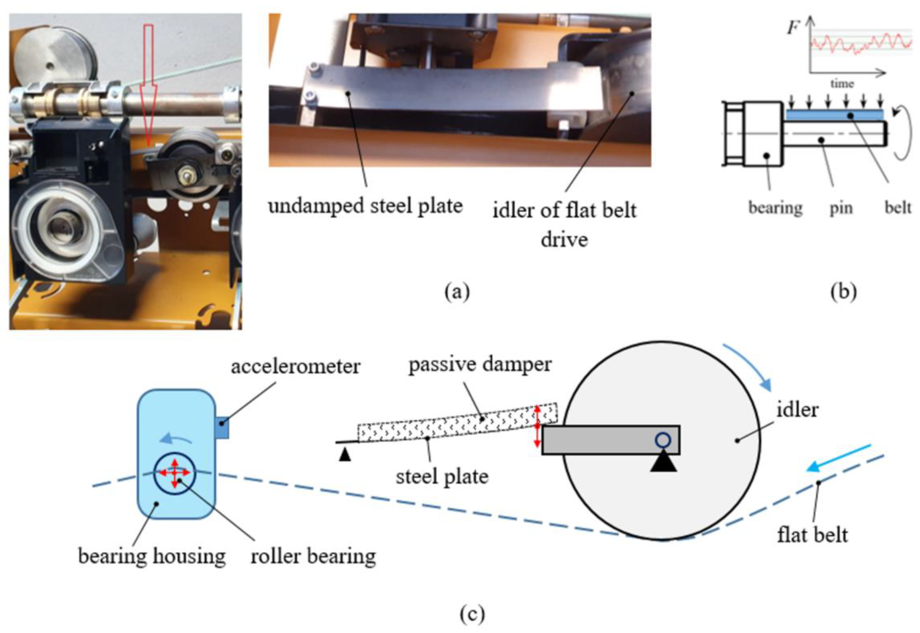
The tested passive dampers were connected through a flexible steel plate to the structure of a testing production machine bench. The steel plate with dimensions 130 × 20 × 0.7 mm (Figure 1a,c) touched the frame of the idler and dampened the vibration of the flat belt that drives the pin of a specific roller bearing, creating pressure (Figure 1b). The main goal of applying the layered passive dampers was to reduce the amplitude of the vibration of the steel plate, the dynamic component and variability of the pressing force subjected at the roller bearing pin, and the amplitude and frequency modulation of vibrations.
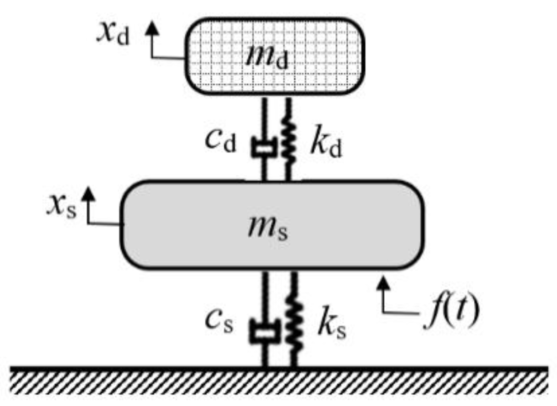
The concept of the mechanical system created by the connection of layered passive dampers is shown in Figure 2. The equation describing the dynamics of the system is as follows:
where xd(t) and xs(t) are the displacement of the passive damper and the structure, respectively, f(t) is the external excitation force, md and ms are the mass of the damper and the structure, respectively, cd and cs are the damping of the passive damper and the structure, respectively, and kd and ks are the stiffness of the passive damper and the structure, respectively. The mechanical system is shown in Figure 2.
The testing bench was driven by an electromotor. The velocity of the flat belt vbelt was 37–68 m/s, causing the roller bearing rotational speed to increase from 70,000 up to 135,000 rpm during testing. The pressing force between the steel plate and the idler frame was 12 ± 2 N. The idler rotational frequency was 80 Hz.
Absolute vibrations were measured using a NI PXI 4426 Sound and Vibration Module (sampling frequency up to 65 kHz), software LabView Sound and Vibration Toolkit, and an Accelerometer PCB Piezotronics model 352A60 (frequency range up to 65 kHz and sensitivity 10 mV/g).
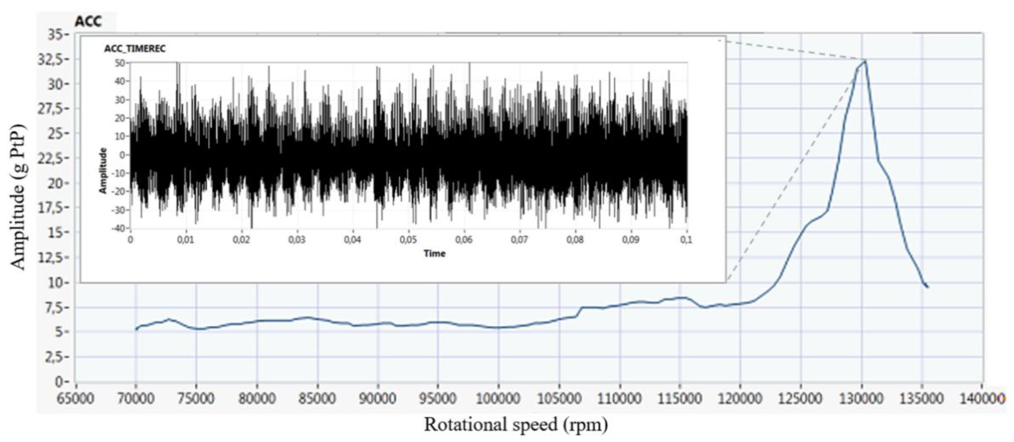
The long-term records of dynamic signals (80 s) for a smooth change of the roller bearing speed from 70,000 to 135,000 rpm were recorded. The accelerometer was placed on the bearing housing, as shown in Figure 1c. The dependence of the amplitude and rotor bearing revolutions for undamped performance is shown in Figure 3. The resonance rotational speed of the rotor roller bearing was 130,200 rpm. The different rotor bearings have different resonance rotational speeds that are about 130,000 rpm. Figure 3 also provides the time record (0.1 s) of the vibration acceleration amplitude in resonance. The vibrations measured using passive dampers were compared for excitation by the same rotor roller bearing. When measuring using other rotor roller bearings, the response had the same character but differed slightly in terms of the size of the amplitude generated and the modulation of the signal.
Figure 3 shows a significant amplitude modulation without the use of a passive damper, i.e., the original state of the mechanical system. The amplitudes of the absolute vibrations are between 10–50 g. The amplitude modulation alternates the contact pressure on the bearing pin and changes the rotational speed of the bearing, causing the torsional oscillations. Finally, such a state makes early destruction and shortens the bearing life.
Materials
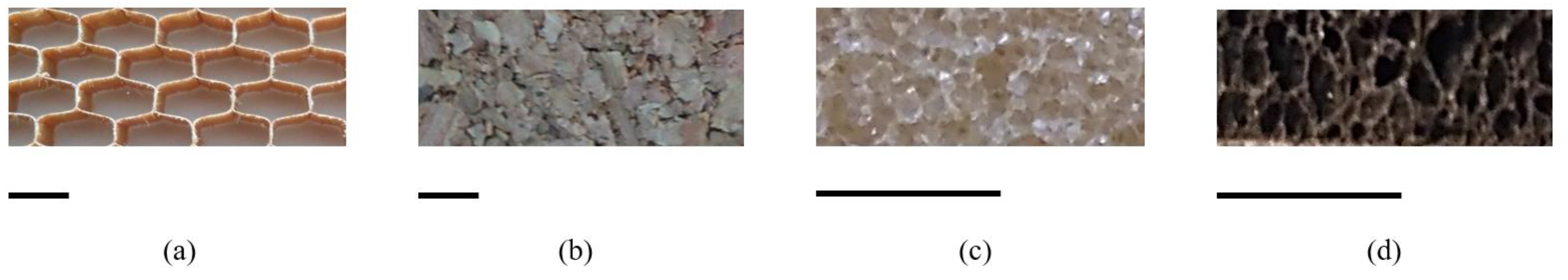
To compare compositions of the multilayer damping system, three types of passive damper (Table 1) were designed and connected to a steel plate as the substrate, with a mass of m0 = 19.7 g. Three compositions were formed from different structures and materials, i.e., over-expanded cell honeycomb made of aramid, closed-cell foam made of natural cork, polyvinyl chloride (PVC) and synthetic rubber, and solid made of synthetic rubber (Figure 4). The layers were fixed together using adhesive layers.
Aramid is an aromatic polyamide with molecules characterized by relatively rigid polymer chains. PVC is a widely used thermoplastic polymer and in this application was used in the form of a rigid cellular structure with closed cells. Synthetic rubber is a polymer in the form of flexible closed-cell foam and solid layers. The bubble form structure of natural cork consists of thin-walled closed cells of smaller dimensions than synthetic foams. The thickness of the individual layers of the materials in passive dampers was 2.5–4 mm.
3. Results
The three types of passive damper were sequentially mounted in the test bench structure, and the dynamic signals were recorded at continuously changing rotational speeds from 70,000 to 135,000 rpm.
The significant differences in vibration amplitude damping for passive dampers of type 1 to 3 were measured (Table 2). During operation without a damper, the maximum amplitude was 50 g Peak, reducing to a maximum of 30, 27, and 26 g Peak for dampers 1, 2, and 3, respectively. The original undamped root mean square (RMS) amplitude value was 33.1 g PtP. The root mean square (RMS) of amplitudes at resonance speed were 25.1, 23.6, and 23.5 g peak to peak (PtP) for dampers 1, 2, and 3, respectively. The most significant reduction was for damper 3, which consisted of flexible rubber foam and solid layers. Table 2 provides the percentage reduction in maximum amplitude and RMS amplitude at resonance for each damper type.
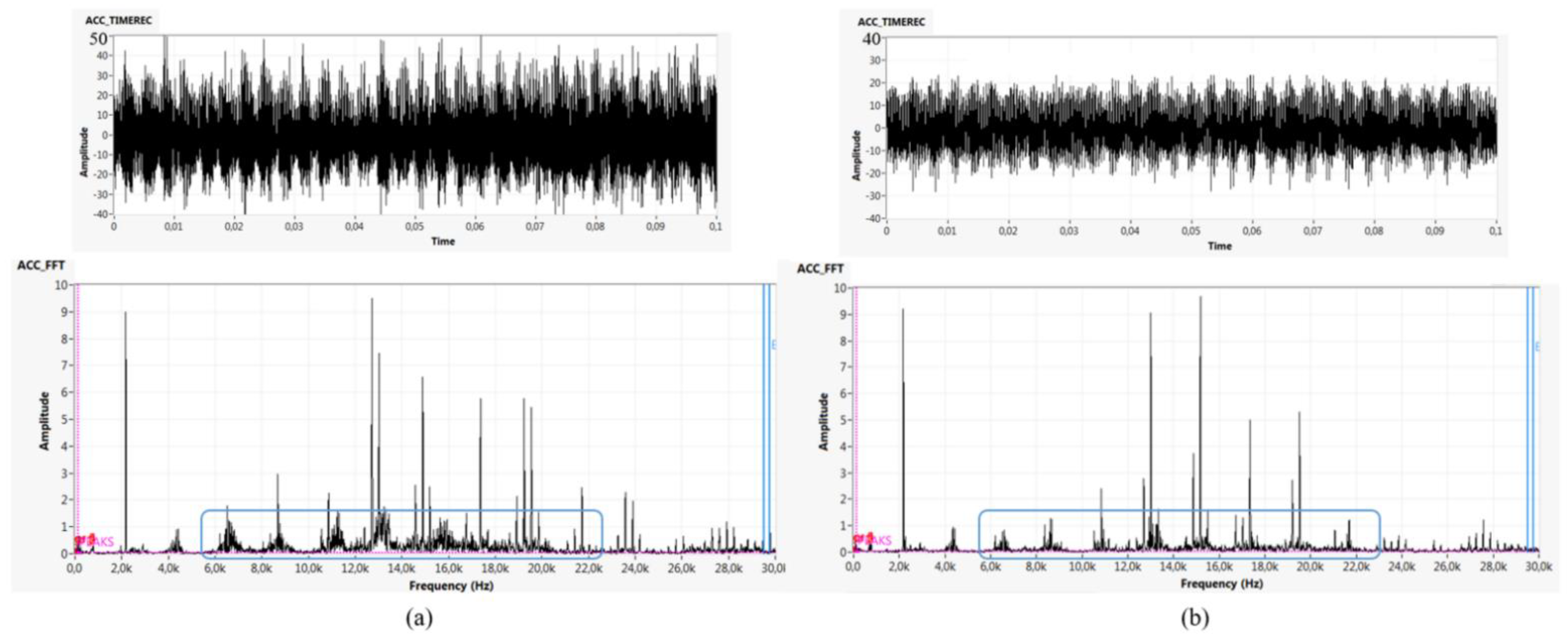
A change in amplitude and frequency modulation is visible when the passive damper is used (Figure 5), comparing the time records of 0.1 s at a resonant speed in Figure 5, up, and (fast Fourier transformation (FFT) spectrums in Figure 5 (below). The frequency 2.15 kHz in Figure 5a,b is for the rotational speed of the rotor bearing. The original sidebands were suppressed by the passive damper. The amplitudes at frequencies of 7, 9, 13, 17, 22, and 24 kHz were also reduced. The overall operation is “calmer”, and the pressure of the flat belt on the bearing pin is more stable.
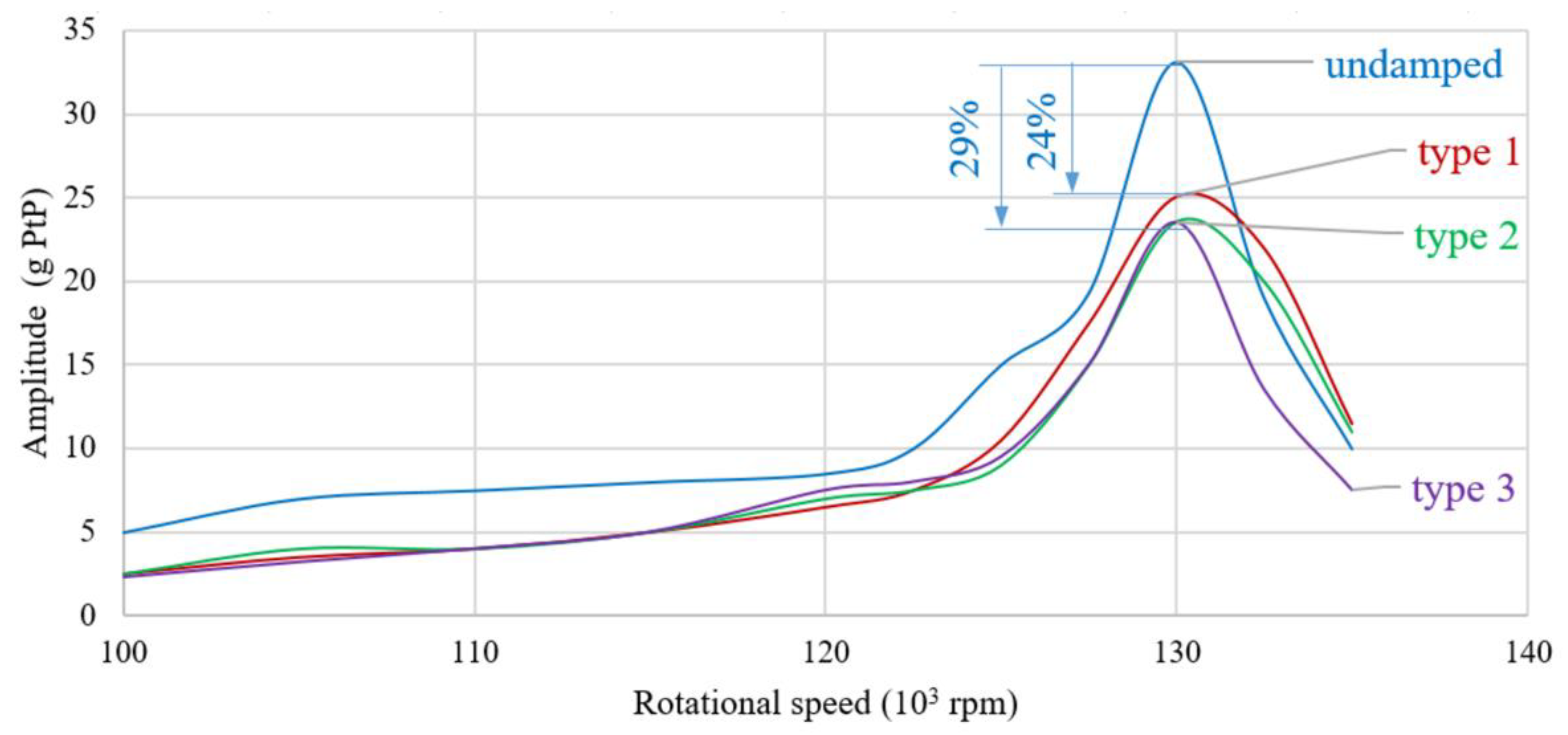
The shape of the resonant peak was also considered as a dynamic parameter. For operation without a damper, the resonant peak is sharp, as it is when damper 3 is used. By contrast, dampers 1 and 2 have preferred rounded resonant peaks (Figure 6).
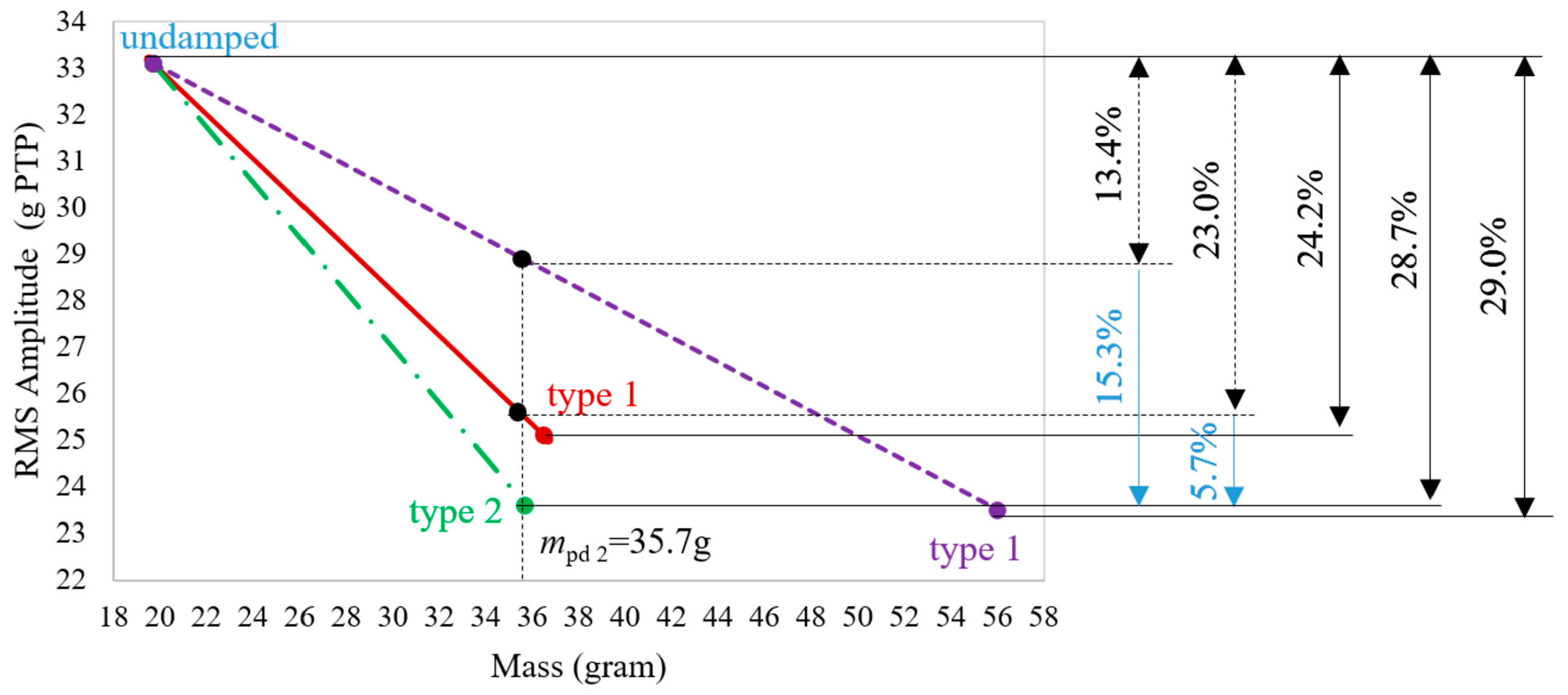
The performance of a passive control system to mitigate a structural vibration depends on its mass and damping status [18]. All of the tested passive dampers have a certain proportion of mass and damping contribution (Figure 6 and Figure 7). The considerable reduction in the RMS amplitude at resonances of 24.2%, 28.7%, and 29.0% was achieved by increasing the mass of the original steel plate by the mass of passive dampers and by using the material damping of layer dampers made of polymers and cork with solid, foam, and honeycomb structure.
However, the mass of each passive damper was different: Damper 3 had the greatest additional mass (36.3 g), and damper 2 had the lowest additional mass (16.0 g), which was 44% of additional mass of damper 3 (Table 3). Their respective results in terms of amplitude decrease were similar, although one might have expected an advantage for damper 3 due to its greater mass. Although almost the same resulting effect was achieved for both, an additional mass of damper 2 was 56% lower.
In addition, the stiffness of non-damped and damped steel plate is not the same. Young’s modulus E of each damper layer material is much lower than Young’s modulus of steel. The homogenized Young’s modulus of passive dampers Epd was determined by its deflection wpd, which was calculated using the computational finite element method (FEM) software. Subsequently, homogenized Epd was determined using the following relationship:
When comparing the bending stiffness (E.I where I is the area moment of inertia) of passive dampers 2 and 3 with the same mass and damping effect, they differed by only 3%. Stiffness was not an advantage for either passive damper 2 or 3.
To determine the material damping contribution of passive dampers 1, 2, and 3, the dependences of the RMS amplitude at resonance with respect to mass (Figure 7) were determined. Passive damper 2 had the minimum mass, i.e., mpd = m0 + m2 = 19.7 g + 16.8 g = 35.7 g. If passive dampers 1 and 3 had the same mass as passive damper 2, their RMS amplitude would have been 25.5 and 28.6 g, respectively, meaning they would reduce the maximum amplitude at resonance by 23.0% and 13.4%, respectively. Moreover, if mass was equal, the damping contribution of passive damper 2 would be 5.7% and 15.3% higher than passive dampers 1 and 3, respectively. Values 15.3% and 5.7% express larger material damping of passive damper 2 compared to passive dampers 1 and 3, respectively. Thus, the flexible rubber foam and solid rubber layers (passive damper 3) provided the lowest damping per unit of mass and an unwanted sharp resonance peak. Compared with passive damper 3, the advantage of passive damper 2 is the material itself, as the stiffness of both was similar and even the mass of damper 2 was 56% lower.
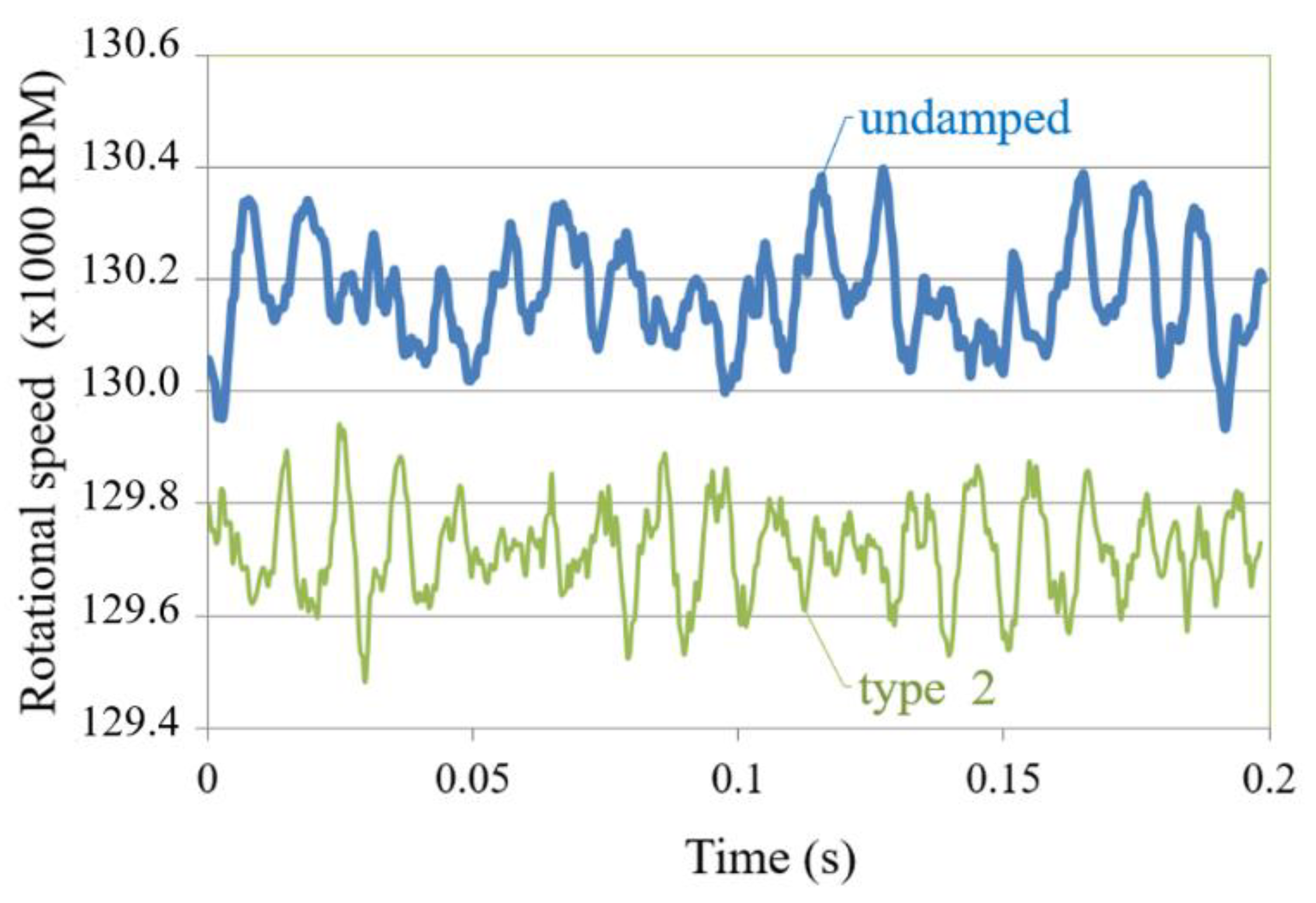
The vibration of the damped driving flat belt caused variability in the pressing force when driving the roller bearing. As a result, the changes in short-term rotational speed are fundamental to the bearing life, as they cause deceleration and acceleration of the rotation of the inner race and the rolling elements. Thus, the additional stress on the bearing cage appears, the kinematic slip of rolling elements increases, and additional torsional oscillations are generated. The average rotational speeds using a non-damped steel plate and a steel plate with passive damper 2 reached a maximum of 130,200 and 129,700 rpm, respectively, and the maximum change of rotational speeds was 410 and 380 rpm, respectively (a 7% decrease in the maximum change for the damped steel plate) (Figure 8). The obtained results are summarized in Table 3.
The values of the amplitude reduction efficiency Ea in Table 3 were evaluated according to [19]
where A is the amplitude reduction relative to the undamped structure and ma is the additional mass of the damper as a proportion of the native mass of the structure. The most efficient amplitude reduction was achieved with passive damper 2.
The performance of one layer of a honeycomb-cored sandwich beam as a viscoelastic damper in [19] provided similar effects. In [10], a more complex internal structure of the viscoelastic composite material passive damper, involving a graphite-phase, provided higher damping expressed by modal loss factor as monolithic layers of traditional viscoelastic material. Passive control systems in [18] intended for buildings, comparing the use of liquid in columns and monolithic volume, were experimentally analyzed regarding mass and damping with similar results. The effects of each mentioned application were united in presented passive dampers with corresponding results.
Damping at Discontinuities—Interfaces and Cells
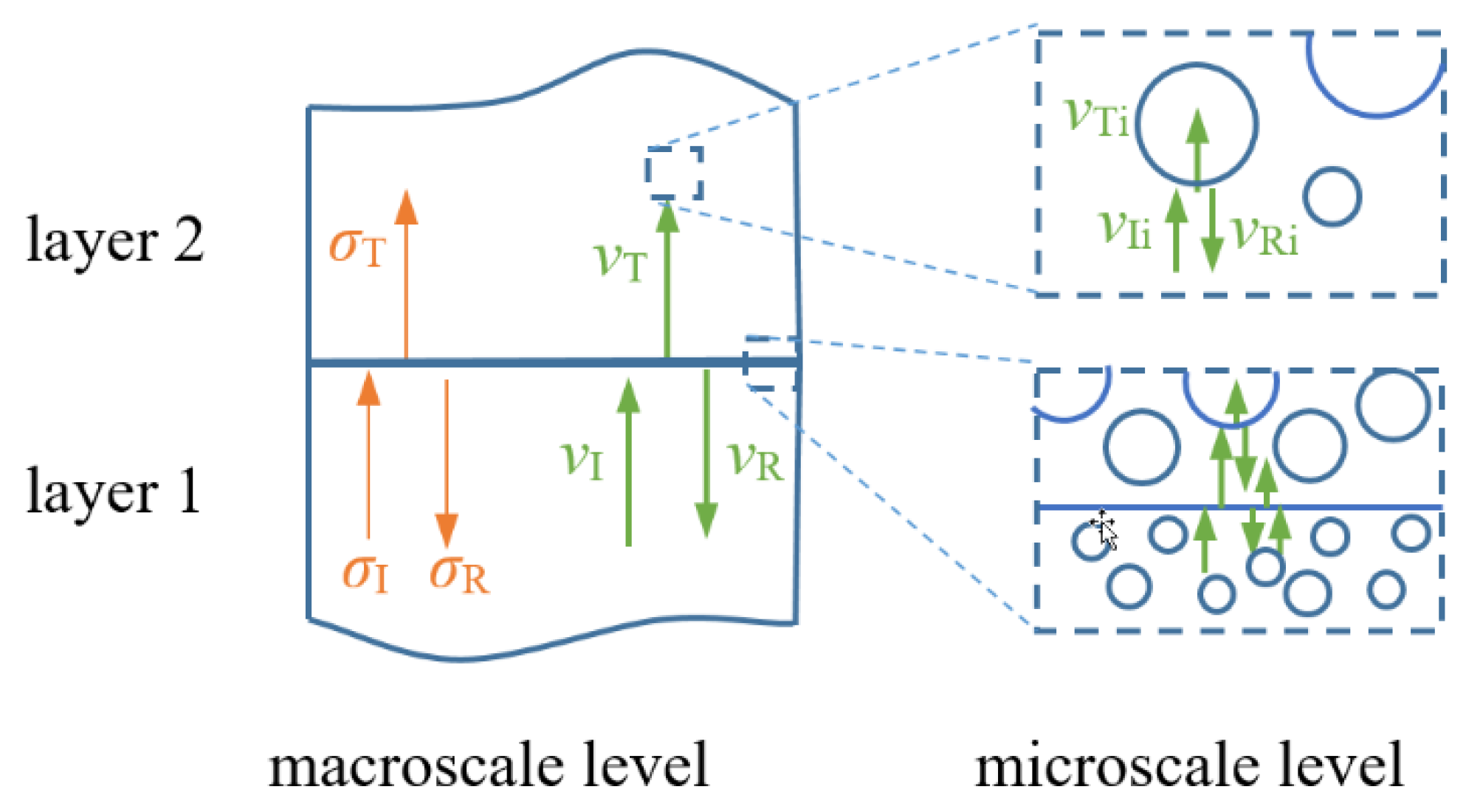
A passive damper consists of materials with different stiffness and density; thus, the longitudinal waves generated by the vibrations of the belt and the pulley partly pass through the damper layers (transmission) and are partly reflected (reflexion), as shown in Figure 9. The interface between layers are discontinuities at the macroscale level and the closed cells of foam structures are discontinuities at the microscale level. At each discontinuity, the equilibrium of stresses (internal forces) and the continuity of mechanical vibration velocities apply.
One of our goals was to reduce the amplitude of mechanical vibrations, and this can be achieved both through discontinuities of the structure (between components) and through discontinuities of used materials, preferably viscoelastic materials. In these areas, some of the incident wave energy goes through the interface and propagates further, which is expressed by the transmission coefficient T (Table 3), while some of the wave energy is reflected back. At discontinuities, the law of momentum must apply, i.e., the momentum of an element of an incident wave is equal to the sum of the momentum of the element from the transmitted and reflected wave (Figure 9). The velocities are as follows:
where vI, vT, and vR are the velocity of the incident, transmission, and reflection wave, respectively.
Analogously for stresses:
Using the relation for mechanical impedance Z:
and substituting into (6) and using (5), the transmission coefficient T is obtained as
The mechanical impedance Z in (8) is calculated by
where ρ is the density of the material and cL is the longitudinal wave speed in that material.
The calculated transmission coefficient T is in accordance with Equations (8) and (9). The values of densities ρ (ρ = m/volume) and longitudinal wave speed cL are calculated according to [20,21]. Having several layers, the values of the transmission coefficient T at the individual interfaces were averaged for each passive damper and are shown in Table 3. Our results confirm that passive damper type 2 is the best absorber of vibration energy (the lowest T).
4. Conclusions
In this study, the passive dampers for vibration control of structures subjected to dynamic loads with a frequency of 1170–2170 Hz were utilized. Three passive layered dampers were designed and experimentally investigated to evaluate their performance. The base steel plate provided the necessary stiffness and strength and the additional layers provided the damping effect. The passive damper layers were able to meet the required objectives, while each passive damper had its own specific characteristics. The main achievements of this study are as follows:
- A passive damper as an absorber of vibration energy can provide a significant damping effect, using mainly material damping resulting from a mostly foam structure of the layered materials used.
- In terms of the passive damper mass, vibrations were damped mostly by the layered rigid polymer and natural cork foams, which reduced the RMS amplitudes at resonance by up to 29% and the maximum amplitude at resonance by up to 48%.
- A significant change in the FFT spectrum was obtained, i.e., resonance peaks in the FFT spectrum decreased due to decreased amplitude modulation of the dynamic signal.
- A 7% reduction in the rotational speed change of the driven rotor bearing, with the positive effect of longer bearing life, was documented.
The parameters influencing the vibrations of mechanical systems are mass, stiffness, and damping. All things considered, passive damper 2 provided the most advantageous parameters. It is a rigid foam polymer and natural foam structure arranged in a passive multilayered composite damper. Passive damper 1 was also suitable, while the least suitable passive damper was 3, especially regarding its mass. Disregarding mass, passive dampers 2 and 3 had a similar effect. The passive dampers are currently being evaluated under long-term testing along with further developments.
Author Contributions
Conceptualization, Z.M.; methodology, P.A.; software, P.A.; validation, Z.M., P.A., and J.Ž.; formal analysis, J.Z.; investigation, Z.M., P.A., J.Ž., and J.Z.; resources, Z.M. and J.Z.; data curation, Z.M. and J.Ž.; writing—original draft preparation, Z.M.; writing—review and editing, Z.M.; visualization, Z.M.; supervision, J.Ž., J.Z., and P.A.; project administration, Z.M.; funding acquisition, J.Z. All authors have read and agreed to the published version of the manuscript.
Funding
This research was funded by Slovak Research and Development Agency, grant number APVV-18-0316 and Agency of Ministry of Education, Science, Research and Sport of the Slovak Republic, grant number VEGA 1/0910/17. The APC was funded by APVV-18-0316.
Institutional Review Board Statement
Not applicable.
Informed Consent Statement
Not applicable.
Data Availability Statement
Not applicable
Conflicts of Interest
The authors declare no conflict of interest.
References
- Zaman, I.B.; Mohamed Salleh, M.; Ismon, M.B.; Manshoor, B.; Khalid, A.; Mohd Sani, M.S.; Araby, S. Study of passive vibration absorbers attached on beam structure. Trans. Tech. Publ. 2014, 660, 511–515. [Google Scholar] [CrossRef] [Green Version]
- Akay, A.; Carcaterra, A. Damping Mechanisms. In Active and Passive Vibration Control of Structures; Hagedorn, P., Spelsberg-Korspeter, G., Eds.; Springer: Vienna, Austria, 2014; Volume 558, pp. 259–300. [Google Scholar]
- Tita, V.; Carvalho, J.D.; Lirani, J. A procedure to estimate the dynamic damped behavior of fiber reinforced composite beams submitted to flexural vibrations. Mater. Res. 2001, 4, 315–321. [Google Scholar] [CrossRef]
- Gardea, F.; Glaz, B.; Riddick, J.; Lagoudas, D.C.; Naraghi, M. Energy dissipation due to interfacial slip in nanocomposites reinforced with aligned carbon nanotubes. ACS Appl. Mater. Interfaces 2015, 7, 9725–9735. [Google Scholar] [CrossRef] [PubMed]
- Ghaedi, K.; Ibrahim, Z.; Adeli, H.; Javanmardi, A. Invited Review: Recent developments in vibration control of building and bridge structures. J. Vibroeng. 2017, 19, 3564–3580. [Google Scholar]
- Nikolić, Ž.; Krstevska, L.; Marović, P.; Smoljanović, H. Shaking table test of scaled model of Protiron dry stone masonry structure. Procedia Eng. 2017, 199, 3386–3391. [Google Scholar] [CrossRef]
- Dong, L.; Lakes, R.S. Advanced damper with negative structural stiffness elements. Smart Mater Struct. 2012, 21, 075026. [Google Scholar] [CrossRef]
- Sikorski, S.; Schoenacher, R.; Schober, M.; Diepolder, W. Vibration Damper for Rotor Housings. U.S. Patent No 5,429,477, 4 July 1995. [Google Scholar]
- Dolgin, B.P. Composite Passive Damping Struts for Large Precision Structures. U.S. Patent No 5,203,435, 20 April 1993. [Google Scholar]
- Kumar, A.; Panda, S. Design of a 1–3 viscoelastic composite layer for improved free/constrained layer passive damping treatment of structural vibration. Compos. Part B 2016, 96, 204–214. [Google Scholar] [CrossRef]
- Ye, H.; Wang, Y.; Liu, B.; Jiang, X. Experimental Study on the Damping Effect of Multi-Unit Particle Dampers Applied to Bracket Structure. Appl. Sci. 2019, 9, 2912. [Google Scholar] [CrossRef] [Green Version]
- Garcia, A. Bearing Damper Having Dispersed Friction Damping Elements. U.S. Patent Application No 11/183,135, 18 January 2007. [Google Scholar]
- Song, Y.; Feng, L.; Liu, Z.; Wen, J.; Yu, D. Suppression of the vibration and sound radiation of a sandwich plate via periodic design. Int. J. Mech. Sci. 2019, 150, 744–754. [Google Scholar] [CrossRef]
- Kormaniková, E. Modal analysis of sandwich panel with composite laminated faces. Vibroeng. Procedia 2019, 23, 105–109. [Google Scholar] [CrossRef]
- Wang, Z.; Liu, J. Mechanical performance of honeycomb filled with circular CFRP tubes. Compos. Part B 2018, 135, 232–241. [Google Scholar] [CrossRef]
- Chin, C.L.; Montgomery, J.M. Method and Apparatus for Reducing Structural Vibration And Noise. U.S. Patent No 9,725,154, 8 August 2017. [Google Scholar]
- Li, L.; Lv, R.; Cai, A.; Xie, M.; Chen, Y.; Huang, G. Low-frequency vibration suppression of a multi-layered elastic metamaterial shaft with discretized scatters. J. Phys. D: Appl. Phys. 2018, 52, 055105. [Google Scholar] [CrossRef] [Green Version]
- Bigdeli, Y.; Kim, D. Damping effects of the passive control devices on structural vibration control: TMD, TLC and TLCD for varying total masses. KSCE J. Civ. Eng. 2016, 20, 301–308. [Google Scholar] [CrossRef]
- Aumjaud, P.; Smith, C.W.; Evans, K.E. A novel viscoelastic damping treatment for honeycomb sandwich structures. Compos. Struct. 2015, 119, 322–332. [Google Scholar] [CrossRef]
- Available online: www.olympus-ims.com/en/ndt-tutorials/thickness-gage/appendices-velocities/ (accessed on 21 January 2021).
- Žiaran, S. Znižovanie Kmitania a Hluku v Priemysle (Vibration and Noise Reduction in Industry); Slovak Technical University Bratislava: Bratislava, Slovak Republic, 2006. (In Slovak) [Google Scholar]
Figure 1.
Idler and undamped steel plate–view and detail (a), pressing force at bearing pin (b), and schematic of testing bench components (c).
Figure 1.
Idler and undamped steel plate–view and detail (a), pressing force at bearing pin (b), and schematic of testing bench components (c).

Figure 2.
Single degree of freedom mechanical system of passive vibration control.

Figure 3.
Vibration acceleration amplitude (g peak to peak) vs. rotational speed (rpm) and a time record of 0.1 s at the peak resonance.
Figure 3.
Vibration acceleration amplitude (g peak to peak) vs. rotational speed (rpm) and a time record of 0.1 s at the peak resonance.

Figure 4.
Aramid over-expanded cell honeycomb (a), natural cork (b), polyvinyl chloride (PVC) foam (c), synthetic rubber foam (d), line below corresponds to 5 mm.
Figure 4.
Aramid over-expanded cell honeycomb (a), natural cork (b), polyvinyl chloride (PVC) foam (c), synthetic rubber foam (d), line below corresponds to 5 mm.

Figure 5.
Time record (up) and fast Fourier transformation (FFT) spectrum (below) for a structure with no damper (a) and a structure with passive damper type 2 (b).
Figure 5.
Time record (up) and fast Fourier transformation (FFT) spectrum (below) for a structure with no damper (a) and a structure with passive damper type 2 (b).

Figure 6.
Comparison of resonance peaks for structures without a damper or with dampers type 1, 2, and 3.
Figure 6.
Comparison of resonance peaks for structures without a damper or with dampers type 1, 2, and 3.

Figure 7.
Comparison of root mean square (RMS) amplitude.

Figure 8.
Rotational speed changes of roller bearings at resonance peak.

Figure 9.
Velocity and stress at discontinuity.


Table 1.
Passive damper 1, 2, and 3.
| Type 1 | rigid PVC foam | Type 2 | rigid PVC foam | Type 3 | flexible rubber foam |
| adhesion layer | adhesion layer | adhesion layer | |||
| aramid honeycomb | natural cork foam | solid rubber | |||
 |  |  | |||
| Mass m1: 16.8 g | Mass m2: 16.0 g | Mass m3: 36.3 g | |||
| Density ρ1: 0.36 g/cm3 | Density ρ2: 0.35 g/cm3 | Density ρ3: 0.79 g/cm3 |
Table 2.
Dynamic parameters at resonant rotational speed.
| Parameter | Undamped | Type 1 | Type 2 | Type 3 |
|---|---|---|---|---|
| RMS amplitude at resonance (g PTP) | 33.1 | 25.1 | 23.6 | 23.5 |
| Reduction in RMS amplitude at resonance | - | 24.2% | 28.7% | 29.0% |
| Maximum amplitude (g Peak) | 50 | 30 | 27 | 26 |
| Maximum amplitude reduction | - | 40% | 46% | 48% |
Table 3.
Summary of results.
| Parameter | Undamped | Type 1 | Type 2 | Type 3 |
|---|---|---|---|---|
| Additional mass (grams) | - | 16.8 | 16.0 | 36.3 |
| Mass of passive damper mpd = m0 + mi | m0 = 19.7 g (mass of steel plate) | 36.5 | 35.7 | 56.0 |
| RMS amplitude at resonance (g PTP) | 33.1 | 25.1 | 23.6 | 23.5 |
| Reduction in RMS amplitude at resonance | - | 24.2% | 28.7% | 29.0% |
| Maximum amplitude (g Peak) | 50 | 30 | 27 | 26 |
| Maximum amplitude reduction | - | 40% | 46% | 48% |
| Resonance peak shape | Undamped sharp | Damped flat | Damped flat | Damped sharp |
| Frequency peaks (kHz) Sidebands | 7, 9, 13, 17, 22, 24 | suppressed | suppressed | suppressed |
| Amplitude reduction efficiency Ea (-) | - | 9.4 | 11.1 | 5.22 |
| Transmission coefficient T (-) | 2.00 | 1.14 | 1.01 | 1.08 |
Publisher’s Note: MDPI stays neutral with regard to jurisdictional claims in published maps and institutional affiliations. |
© 2021 by the authors. Licensee MDPI, Basel, Switzerland. This article is an open access article distributed under the terms and conditions of the Creative Commons Attribution (CC BY) license (https://creativecommons.org/licenses/by/4.0/).
Share and Cite
MDPI and ACS Style
Murčinková, Z.; Živčák, J.; Zajac, J.; Adamčík, P. Passive Multi-Layer Composite Damper of Flat Belt Tensioner Idler. Appl. Sci. 2021, 11, 3267. https://0-doi-org.brum.beds.ac.uk/10.3390/app11073267
AMA Style
Murčinková Z, Živčák J, Zajac J, Adamčík P. Passive Multi-Layer Composite Damper of Flat Belt Tensioner Idler. Applied Sciences. 2021; 11(7):3267. https://0-doi-org.brum.beds.ac.uk/10.3390/app11073267
Chicago/Turabian StyleMurčinková, Zuzana, Jozef Živčák, Jozef Zajac, and Pavel Adamčík. 2021. "Passive Multi-Layer Composite Damper of Flat Belt Tensioner Idler" Applied Sciences 11, no. 7: 3267. https://0-doi-org.brum.beds.ac.uk/10.3390/app11073267
Note that from the first issue of 2016, this journal uses article numbers instead of page numbers. See further details here.