
Study on Design of Non-Circular Gears for Speed Control of the Squid Belly Opening and Gutting Machine (SBOGM)

Abstract
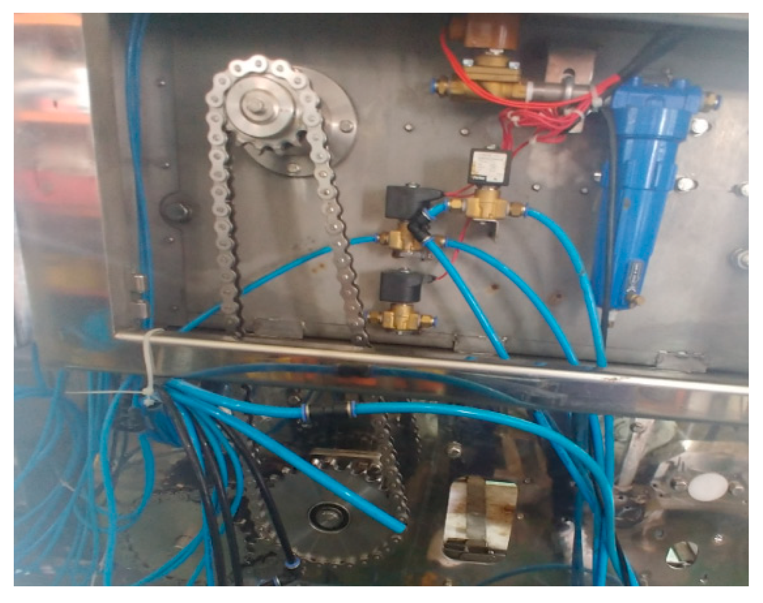
:1. Introduction
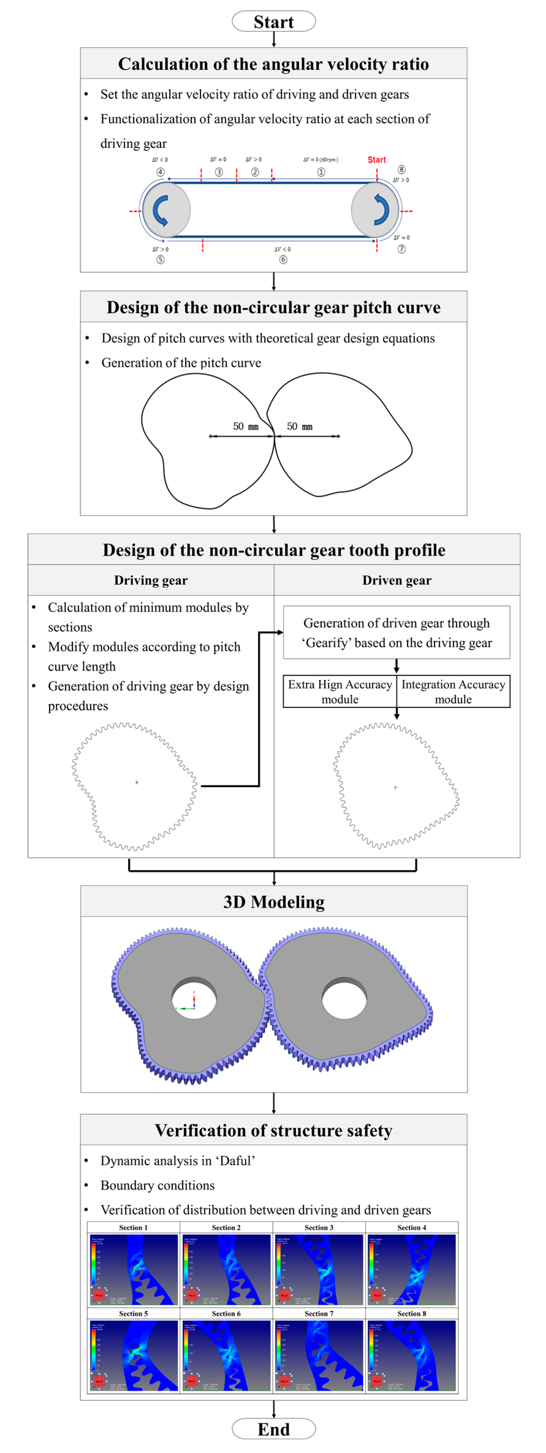
2. Design of the Non-Circular Gear
2.1. Design of the Pitch Curve
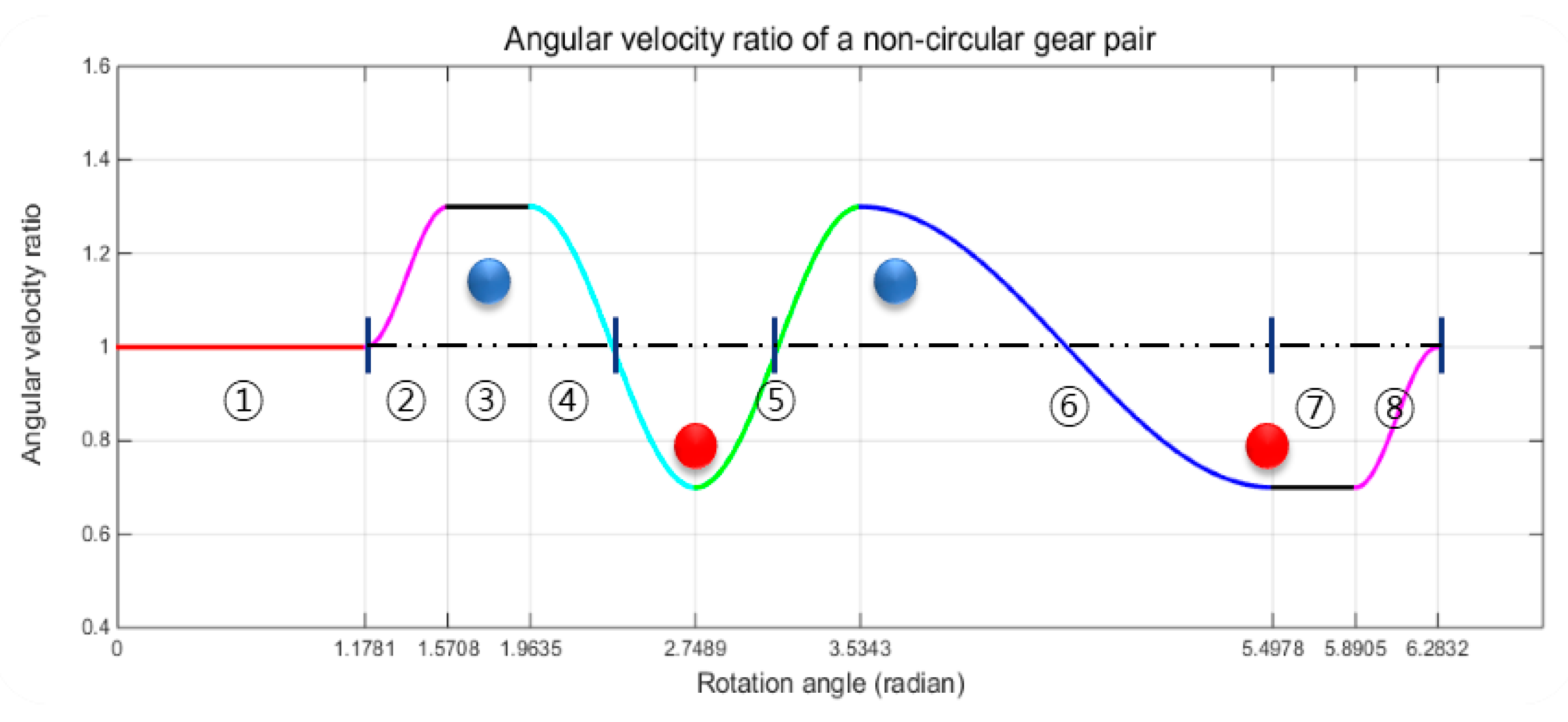
2.1.1. Design of the Angular Velocity Ratio
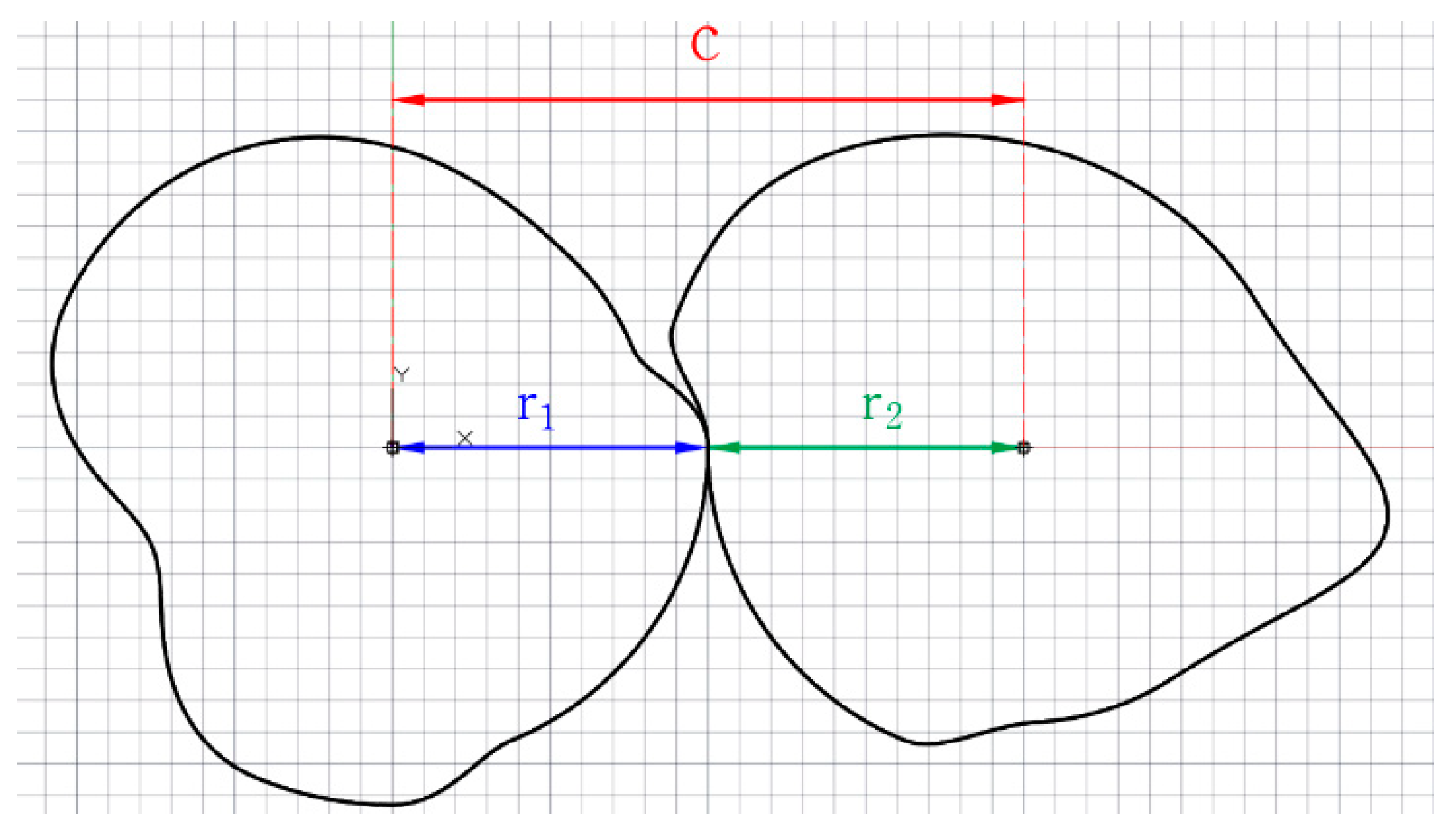
2.1.2. Design of the Pitch Curve
2.1.3. Derivation of the Pitch Curve
2.2. Tooth Profile Design
2.2.1. Calculation of Minimum Module
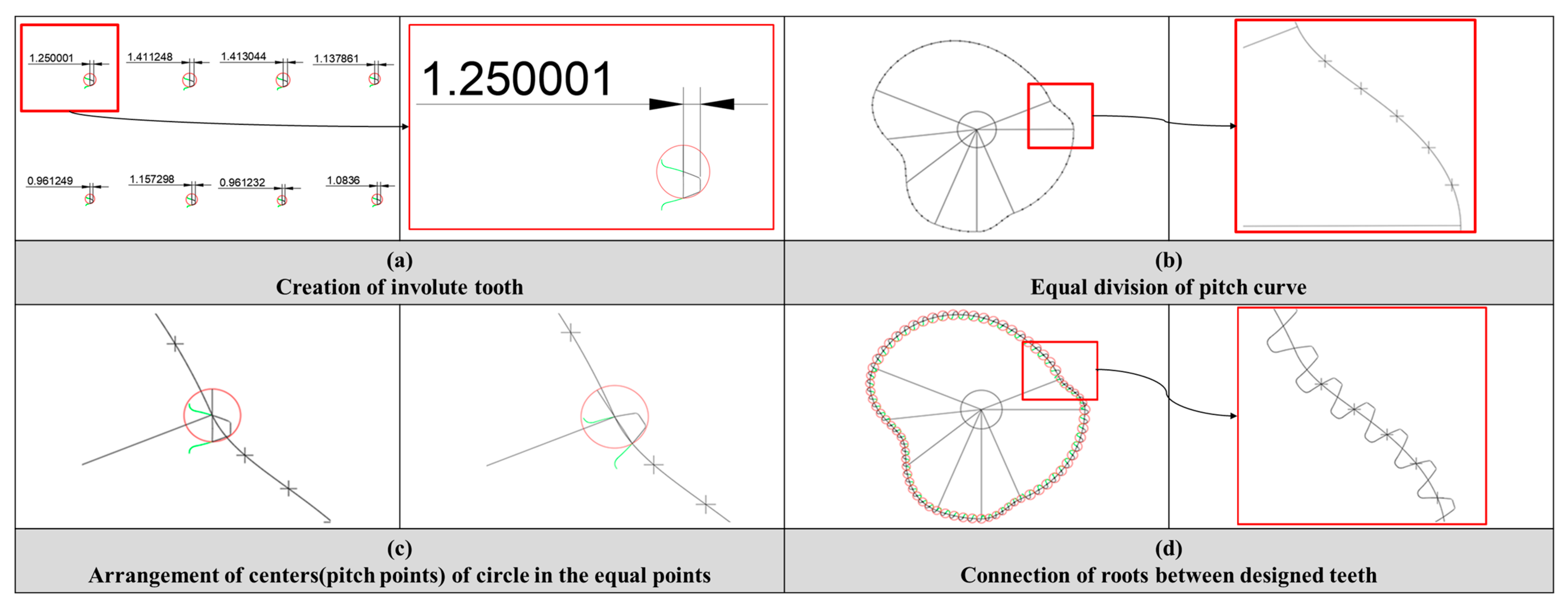
- Creation of involute tooth according to the modules calculated (Figure 7a).
- Equal division of pitch curve at each section according to the modules adjusted (Figure 7b).
- Arrangement of centers (pitch points) of circle in the equal points by translation and rotation (Figure 7c).
- Connection of roots between designed teeth (Figure 7d).
2.2.2. Design of the Tooth Profile of the Driven Gear
3. Verification of Structural Safety of Non-Circular Gears
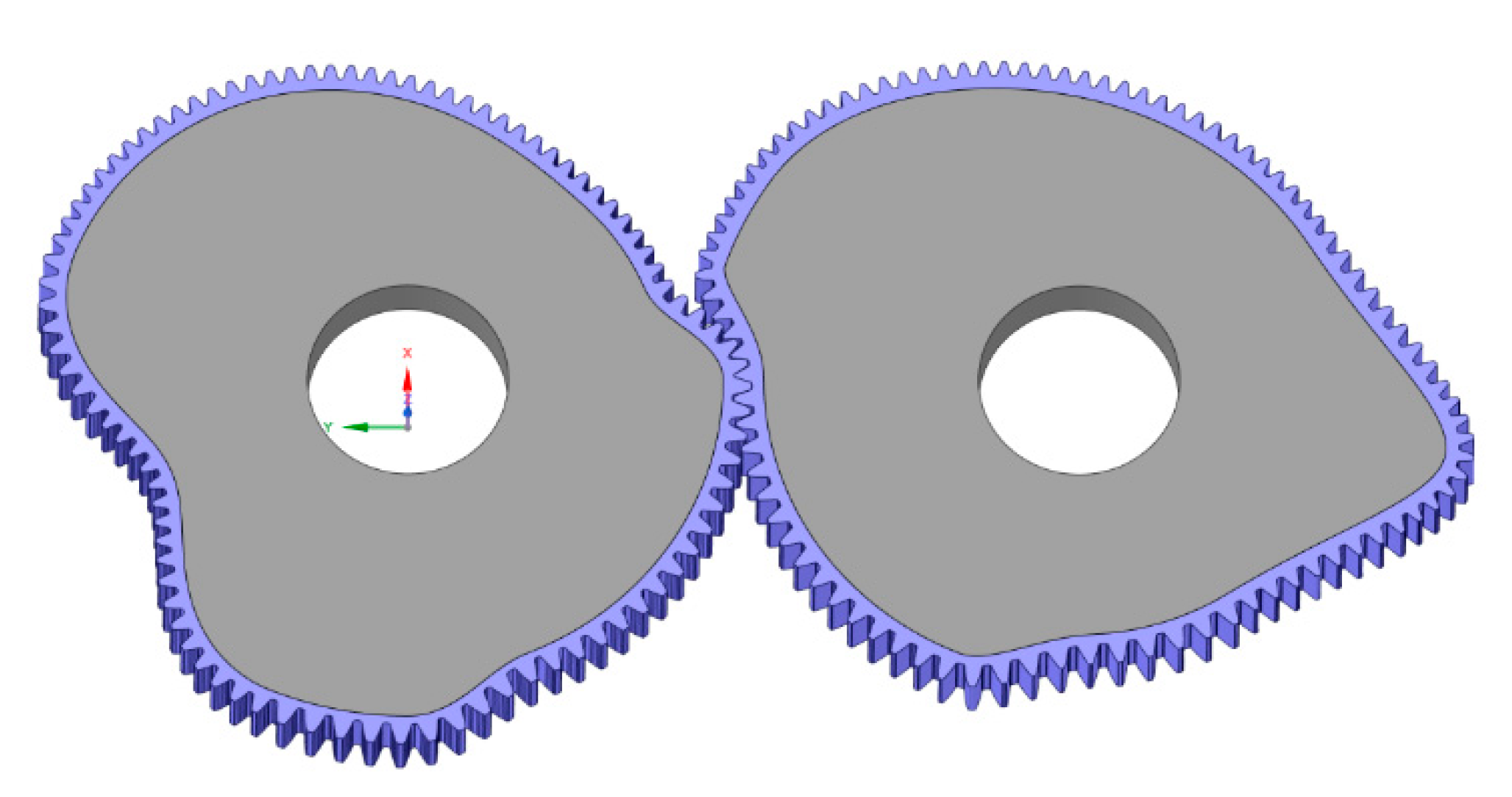
3.1. 3D Modeling
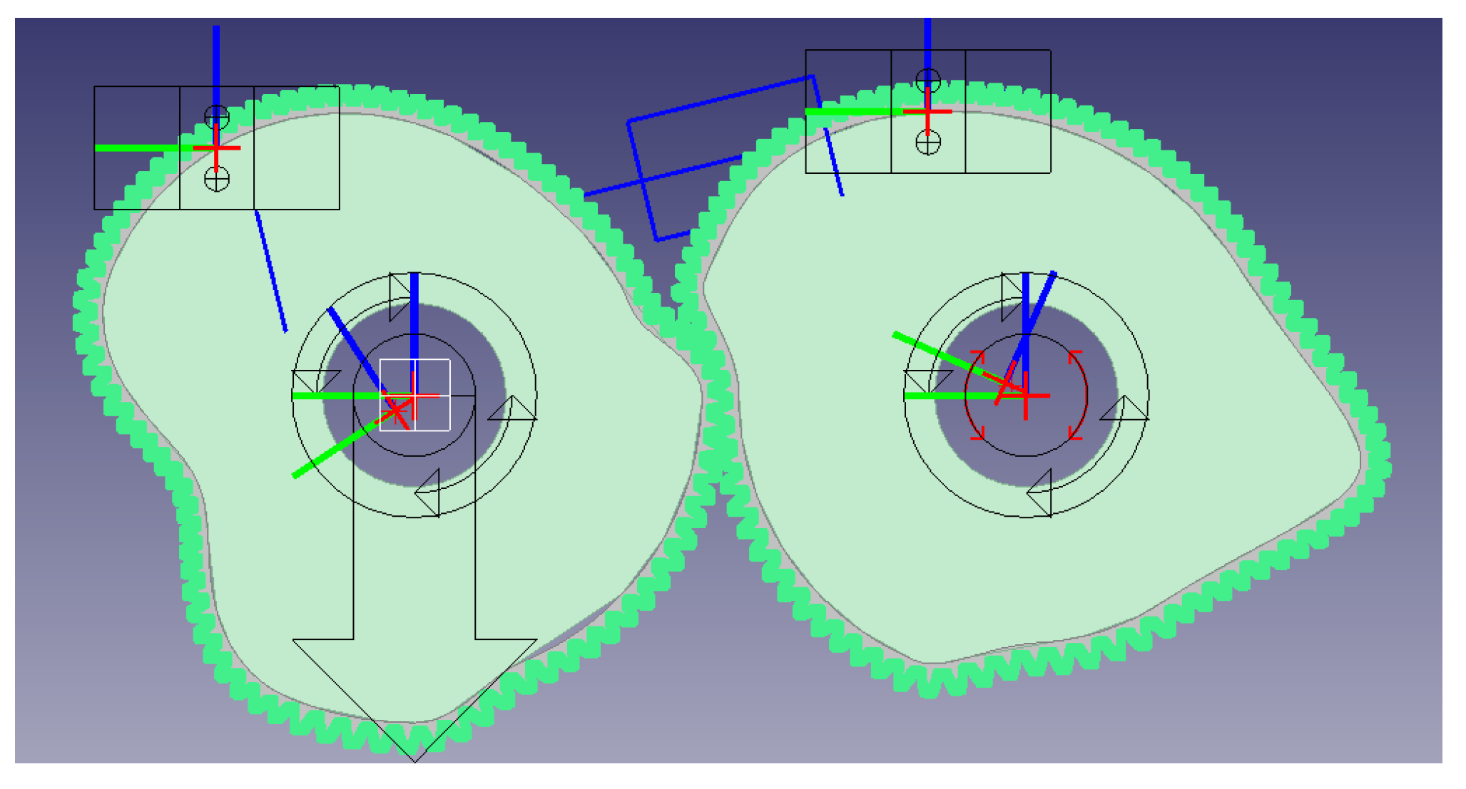
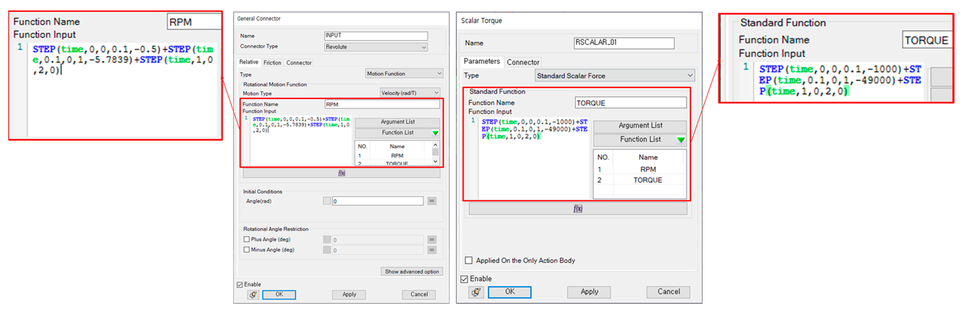
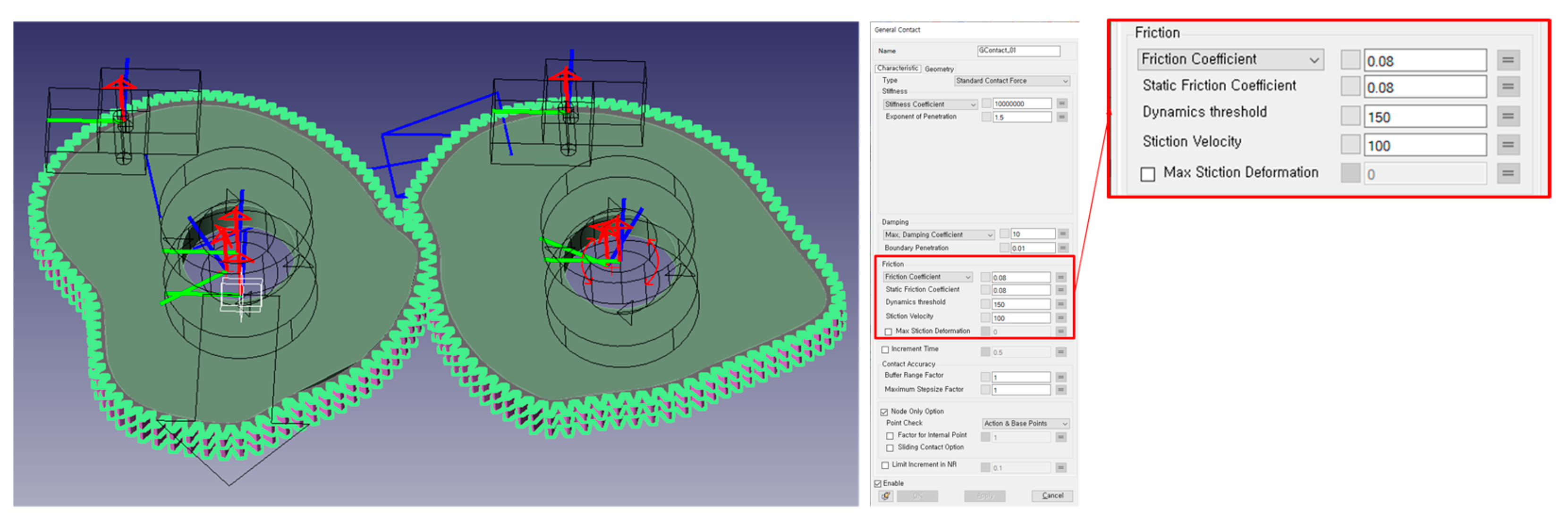
3.2. Boundary Conditions
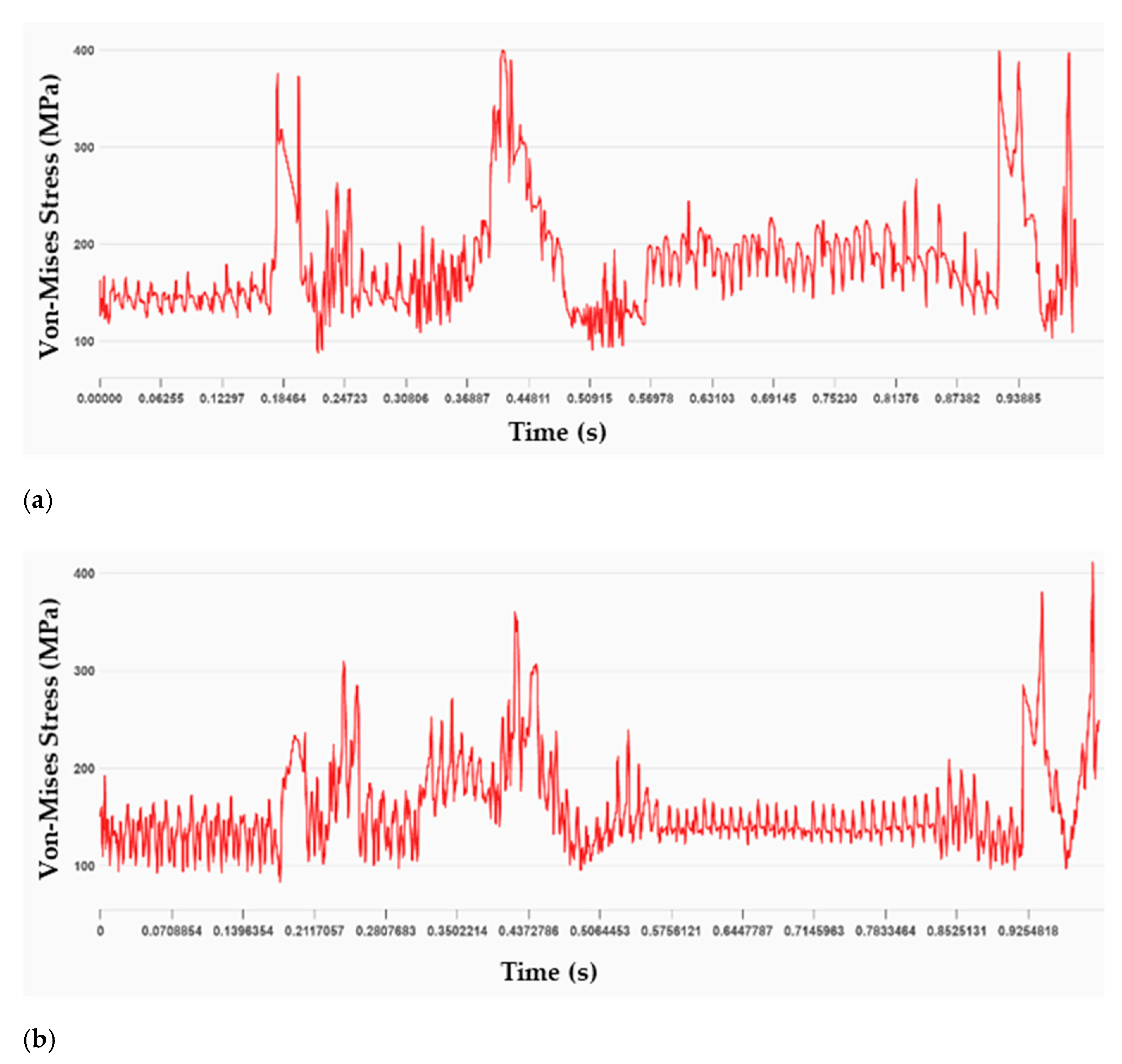
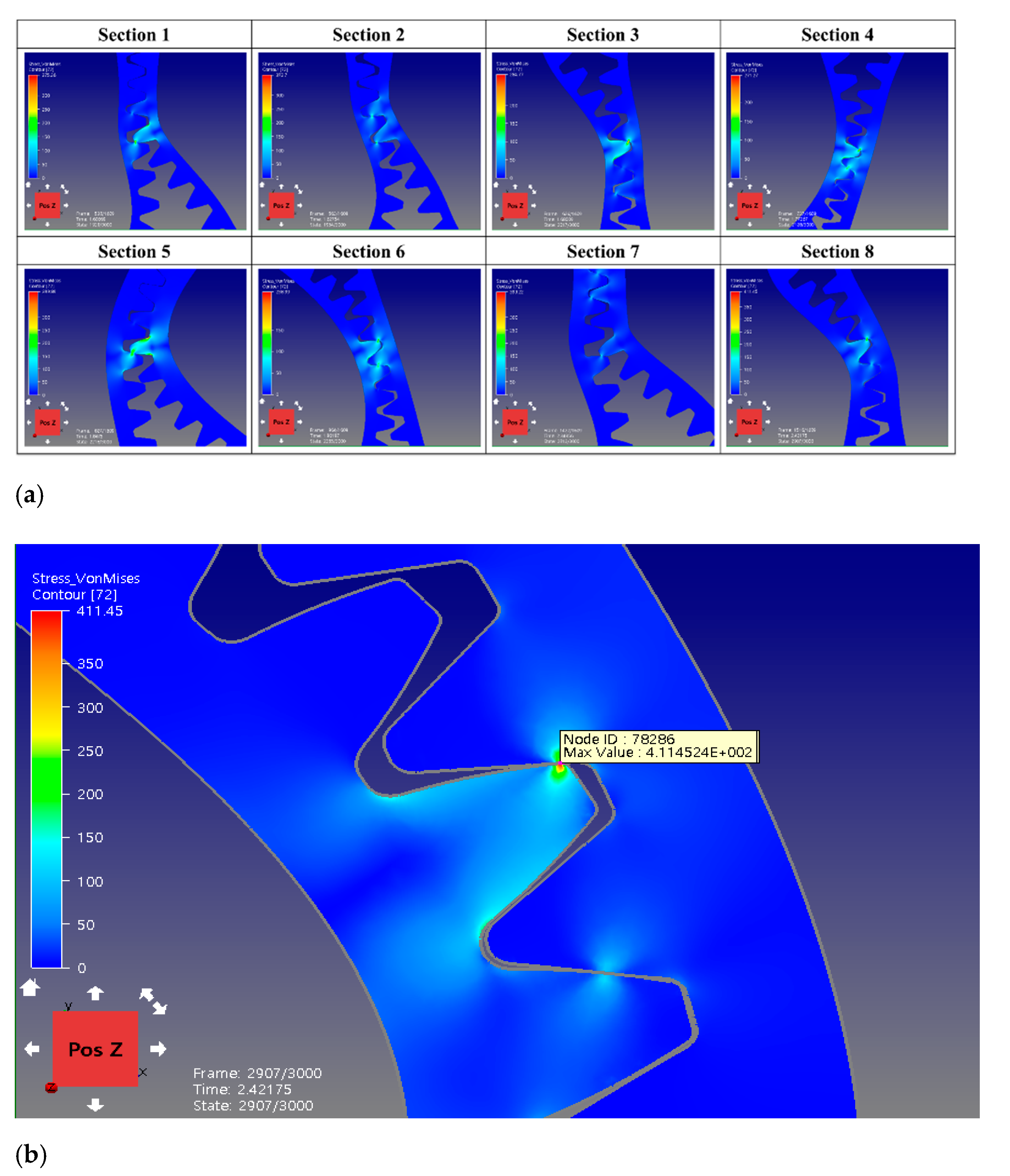
3.3. Analysis Results
4. Conclusions
- (1)
- To improve the efficiency of the processes of the existing Squid Belly Opening and Gutting Machine (SBOGM) and to reduce impact during rotation, non-circular gears alternative to the chain gear and spur gear were developed for the SBOGM.
- (2)
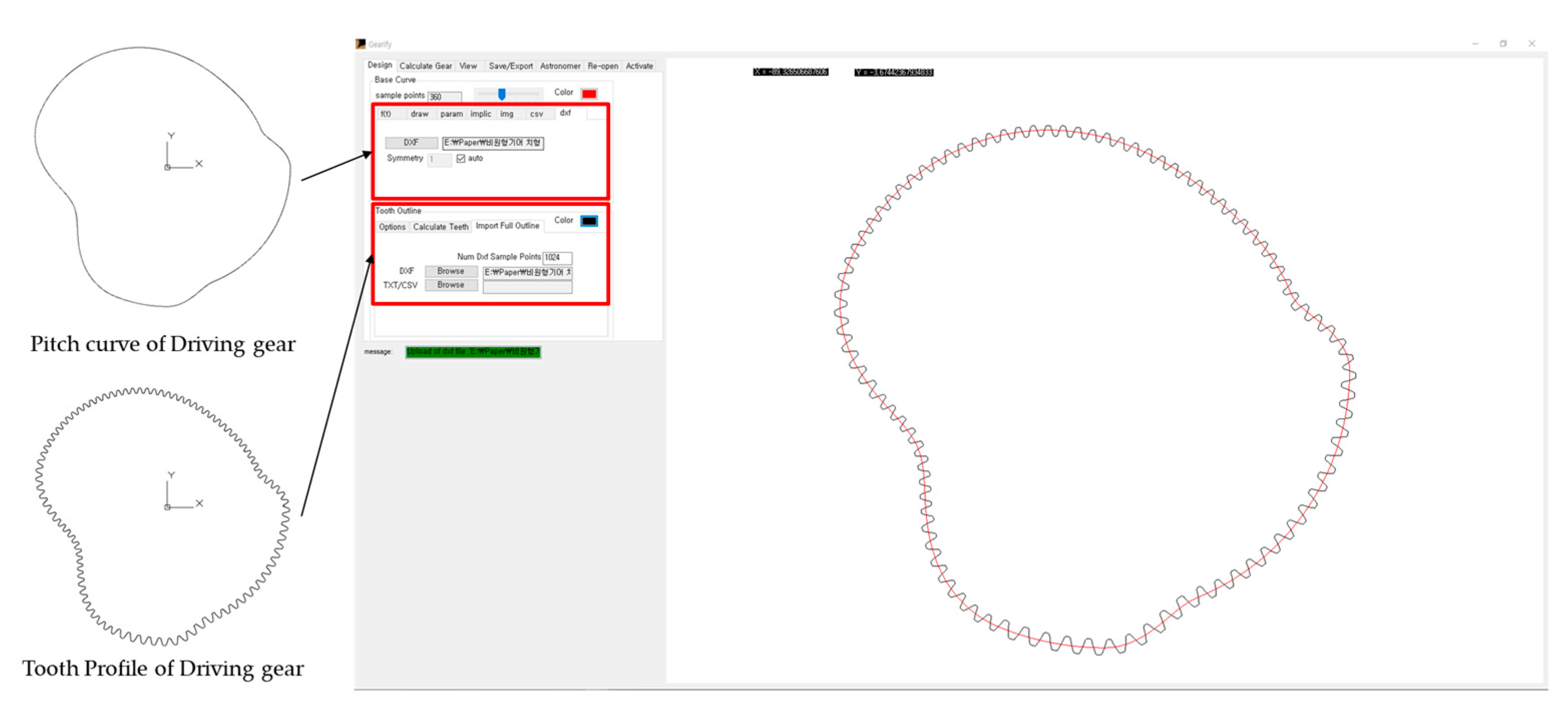
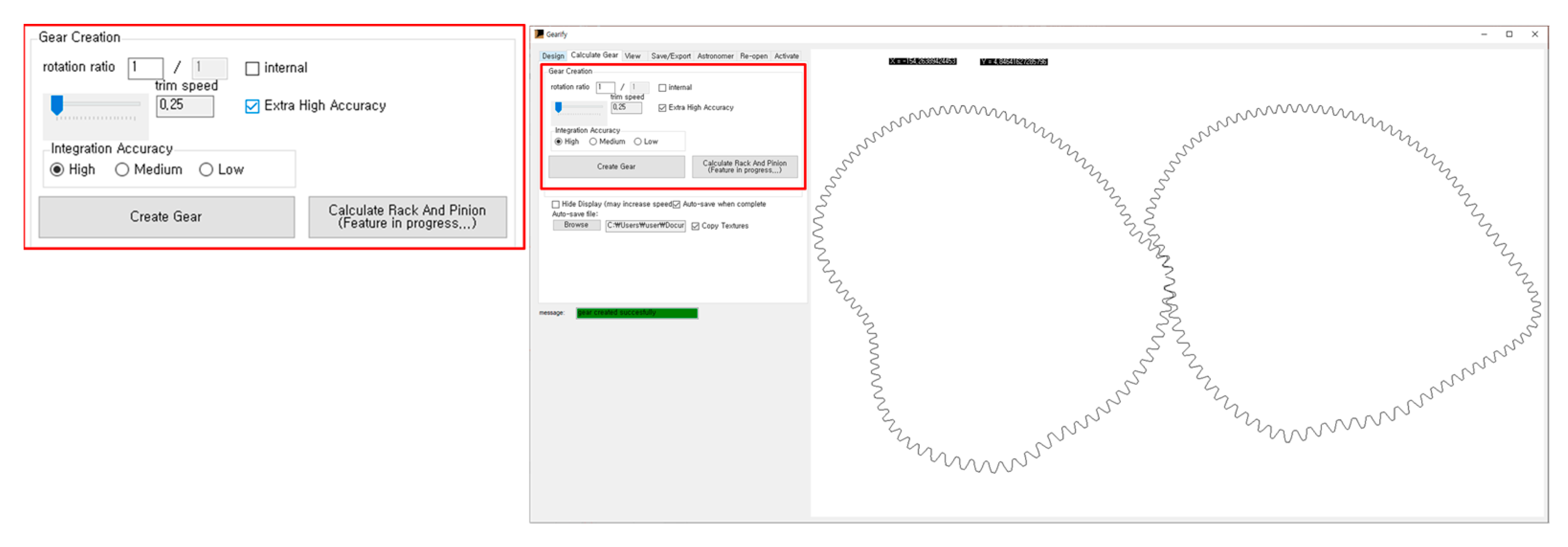
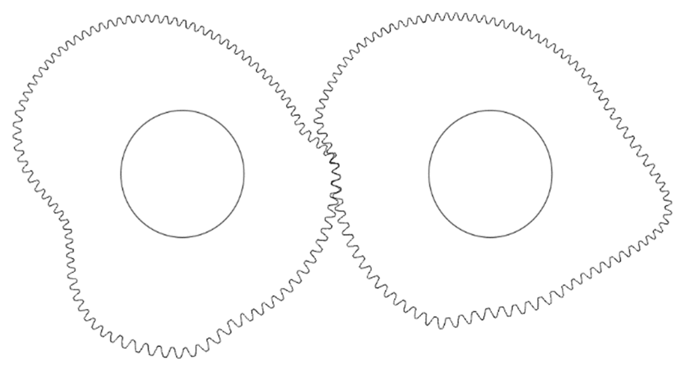
- Driving gear was designed according to the tooth design procedures suggested for non-circular gears, and the driven gear was generated through its program ‘Gearify’ based on the designed driving gear.
- (3)
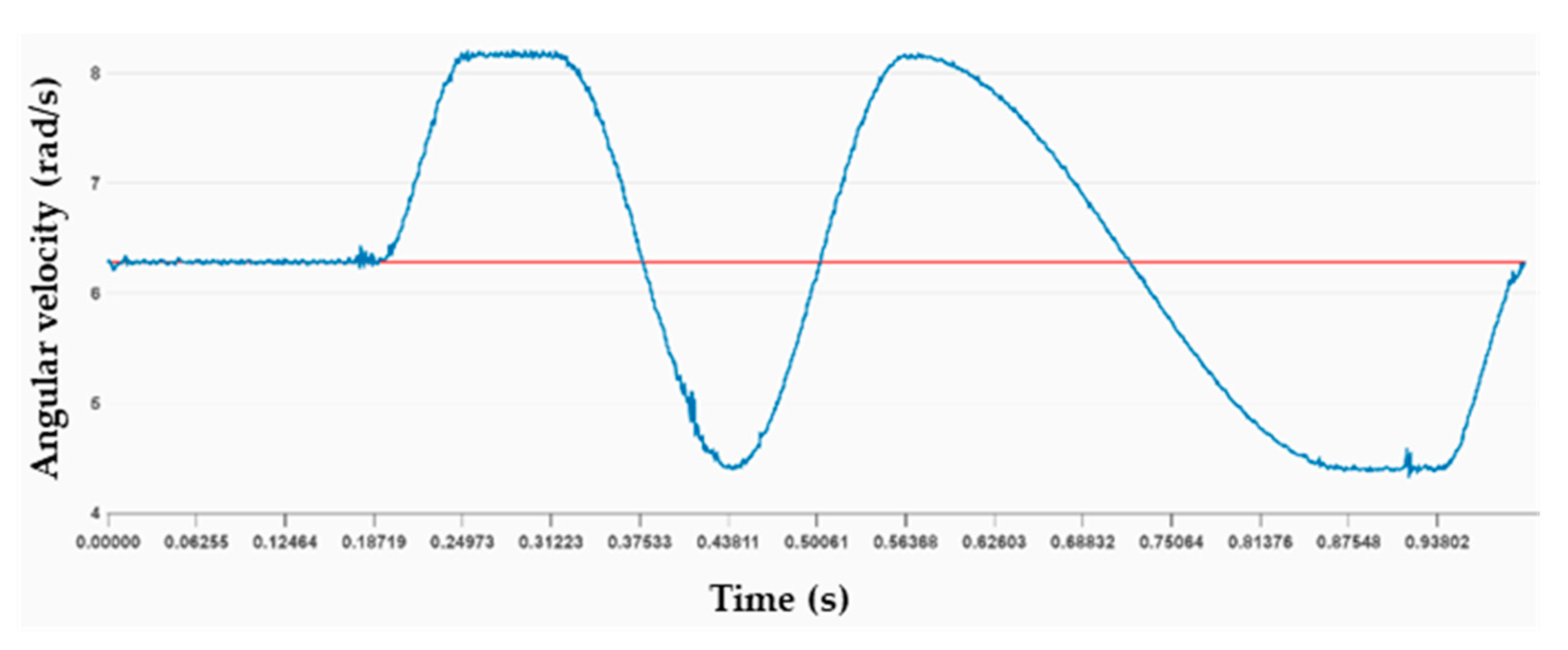
- The angular velocity ratio during one revolution of the driving gear was extracted through ‘DAFUL’ analysis, whose results are identical to the graph of angular velocity ratio obtained by theoretical calculations.
- (4)
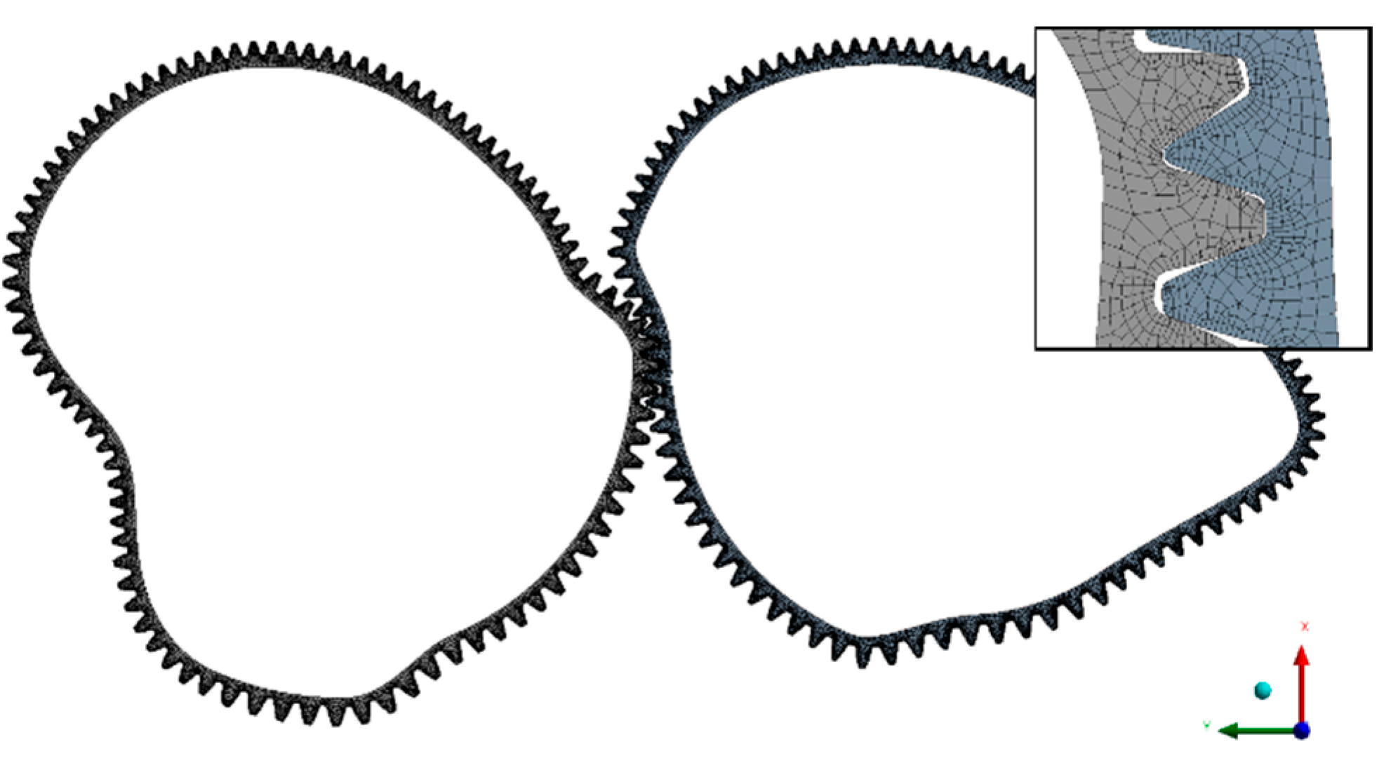
- Flexible body dynamics analysis was conducted using the commercial program ‘DAFUL’, and the maximum Von-Mises stress at the Section (8) was 411.45 MPa, which was lower than the yield strength of 445 MPa, so the structural safety was considered to be safe.
Author Contributions
Funding
Institutional Review Board Statement
Informed Consent Statement
Data Availability Statement
Conflicts of Interest
References
- Wang, H.; Liu, J. Tooth Profile Design and Kinematic Mechanism Simulation of Higher-order Elliptic Gears Based on MAPLE. J. Appl. Sci. 2014, 14, 362–367. [Google Scholar]
- Lee, S. Design of Noncircular Gears for Wire EDM. J. KSTLE 2008, 24, 221–227. [Google Scholar]
- Niculescum, M.; Andrei, L.; Cristescu, A. Generation of noncircular gears for variable motion of the crank-slider mechanism. In Proceedings of the 7th International Conference on Advanced Concepts in Mechanical Engineering, Iasi, Romania, 9–10 June 2016. [Google Scholar]
- Wu, Z.; Hu, C.; Kong, D.; Yao, H. The parameter Design Resarch of Non-circular Gear based on MATLAB and Pro/E. In Proceedings of the 2011 International Conference on Electric Information and Control Engineering, Wuhan, China, 15–17 April 2011; pp. 6276–6279. [Google Scholar]
- Zhou, K.; Li, Y.; Li, C.; Wang, C. Non-circular gear kinematics simulation based on ADAMS. In Proceedings of the International Conference on Intelligent Computation Technology and Automation, Nanchang, China, 14–15 June 2015. [Google Scholar]
- Kang, D.W.; Shin, J.H.; Kim, J.S.; Kim, D.W. Study on A Shape Design Method for General Non-Circular Gear and Mating Gear Systems. J. Korea Soc. Precis. Eng. 1999, 99, 668–671. [Google Scholar]
- Xu, H.; Fu, T.; Song, P.; Zhou, M.; Fu, G.; Mitra, N.J. Computational Design and Optimization of Non-Circular Gears. Comput. Graph. Forum 2020, 39, 399–409. [Google Scholar] [CrossRef]
- Choi, S.-H. A Study on the Proper Scope for Pressure Angle, Ratio of Tooth Number & Radius of Curvature in Non-Circular Gears. J. Korea Soc. Precis. Eng. 1997, 14, 52–63. [Google Scholar]
- Niculescu, M.; Andrei, L. Using noncircular gears for the unloading door kinematics modification. In Proceedings of the MATEC Web of Conferences, Iasi, Romania, 24–27 May 2017; Volume 112, p. 6013. [Google Scholar]
- Vasie, M.; Andrei, L. Analysis of Noncircular Gears Meshing. Mech. Test. Diagn. 2012, 4, 70–78. [Google Scholar]
- Zheng, F.; Hua, L.; Han, X.; Li, B.; Chen, D. Synthesis of indexing mechanisms with non-circular gears. Mech. Mach. Theory 2016, 105, 108–128. [Google Scholar] [CrossRef]
- Zhang, J.; Bin, Y.U.; Shui, J.; Qi, X. Design of the pitch curves of non-circular gears based on MATLAB. Mach. Electron. 2016, 34, 17–20. [Google Scholar]
- Lyashkov, A.A.; Panchuk, K.L.; Khasanova, I.A. Automated Geometric and Computer-aided Non-Circular Gear Formation Modeling. Mechanical Science and Technology Update. J. Phys. Conf. Ser. 2018, 1050, 012049. [Google Scholar] [CrossRef]
- Mundo, D. Geometric design of a planetary gear train with non-circular gears. Mech. Mach. Theory 2006, 41, 456–472. [Google Scholar] [CrossRef]
- Cristescu, A.; Cristescu, B.; Andrei, L. Designing Multispeed Gear Pitch Curves. Appl. Mech. Mater. 2014, 657, 480–484. [Google Scholar] [CrossRef]
- Tsay, M.F.; Fong, Z.H. Study on the generalized mathematical model of noncircular gears. Math. Comput. Model. 2005, 41, 555–569. [Google Scholar] [CrossRef]
- Khan, S. Simulation and analysis of transmission error in helical non-circular gear model. IJMET 2015, 6, 128–136. [Google Scholar]
- Cristescu, A.; Cristescu, B.; Andrei, L. Finite element analysis of multispeed noncircular gears. Appl. Mech. Mater. 2015, 808, 246–251. [Google Scholar] [CrossRef]


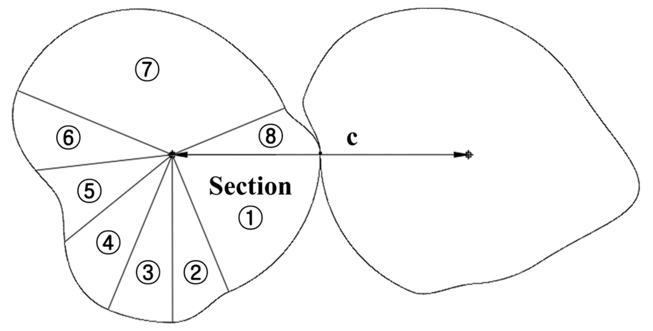
| Section | θ [Radian] | |
|---|---|---|
| ① | ||
| ② | ||
| ③ | ||
| ④ | ||
| ⑤ | ||
| ⑥ | ||
| ⑦ | ||
| ⑧ |
| Section | 1 | 2 | 3 | 4 | 5 | 6 | 7 | 8 |
|---|---|---|---|---|---|---|---|---|
| Pinion rotation angle (°) | 0~67.5 | 67.5~90 | 90~112.5 | 112.5~157.5 | 157.5~202.5 | 202.5~315 | 315~337.5 | 337.5~360 |
| Gear rotation angle (°) | 0~67.5 | 67.5~93.37 | 93.37~115.87 | 115.87~160.89 | 160.89~205.87 | 205.87~318.04 | 318.04~340.54 | 340.54~360 |
| Radius of Driving Gear (mm) | 50 | ↑ | 66.67 | ↓ | ↑ | ↓ | 33.33 | ↑ |
| Radius of Driven Gear (mm) | 50 | ↓ | 33.33 | ↑ | ↓ | ↑ | 66.67 | ↓ |
| Pitch curve length (mm) | 58.90 | 22.17 | 22.20 | 28.60 | 27.18 | 29.09 | 114.75 | 20.42 |
| Total pitch curve length (mm) | 323.31 | |||||||
| Angle (°) | Length (mm) | Theory Min Module | Number of Teeth | Module |
|---|---|---|---|---|
| 0°~67.5° | 58.90 | 1.2 | 15 | 1.25 |
| 67.5°~90° | 22.17 | 1.2 | 5 | 1.41 |
| 90°~112.5° | 22.20 | 1.316 | 5 | 1.41 |
| 112.5°~141° | 28.60 | 1.08 | 8 | 1.14 |
| 141°~173.5° | 27.18 | 0.96 | 9 | 0.96 |
| 173.5°~202.5° | 29.09 | 1.08 | 8 | 1.15 |
| 202.5°~337.5° | 114.75 | 0.96 | 38 | 0.96 |
| 337.5°~360° | 20.42 | 0.96 | 6 | 1.08 |
| Range (°) | Max. Stress (MPa) | ||
|---|---|---|---|
| Driving Gear | Driven Gear | ||
| Section 1 | 0~67.5 | 375.36 | 201.99 |
| Section 2 | 67.5~90 | 372.70 | 309.43 |
| Section 3 | 90~112.5 | 256.76 | 284.77 |
| Section 4 | 112.5~141 | 218.25 | 271.27 |
| Section 5 | 141~173.5 | 399.89 | 360.14 |
| Section 6 | 173.5~202.5 | 193.58 | 238.99 |
| Section 7 | 202.5~337.5 | 399.22 | 285.49 |
| Section 8 | 337.5~360 | 387.65 | 411.45 |
Publisher’s Note: MDPI stays neutral with regard to jurisdictional claims in published maps and institutional affiliations. |
© 2021 by the authors. Licensee MDPI, Basel, Switzerland. This article is an open access article distributed under the terms and conditions of the Creative Commons Attribution (CC BY) license (https://creativecommons.org/licenses/by/4.0/).
Share and Cite
Jang, H.-S.; Lee, C.-H.; Park, G.-Y.; Kim, C. Study on Design of Non-Circular Gears for Speed Control of the Squid Belly Opening and Gutting Machine (SBOGM). Appl. Sci. 2021, 11, 3268. https://0-doi-org.brum.beds.ac.uk/10.3390/app11073268
Jang H-S, Lee C-H, Park G-Y, Kim C. Study on Design of Non-Circular Gears for Speed Control of the Squid Belly Opening and Gutting Machine (SBOGM). Applied Sciences. 2021; 11(7):3268. https://0-doi-org.brum.beds.ac.uk/10.3390/app11073268
Chicago/Turabian StyleJang, Hyo-Seong, Chang-Hyun Lee, Gun-Young Park, and Chul Kim. 2021. "Study on Design of Non-Circular Gears for Speed Control of the Squid Belly Opening and Gutting Machine (SBOGM)" Applied Sciences 11, no. 7: 3268. https://0-doi-org.brum.beds.ac.uk/10.3390/app11073268