
The Deltah Lab, a New Multidisciplinary European Facility to Support the H2 Distribution & Storage Economy

 ,
,  ,
,
Abstract
:1. Introduction
2. Hydrogen Storage Systems
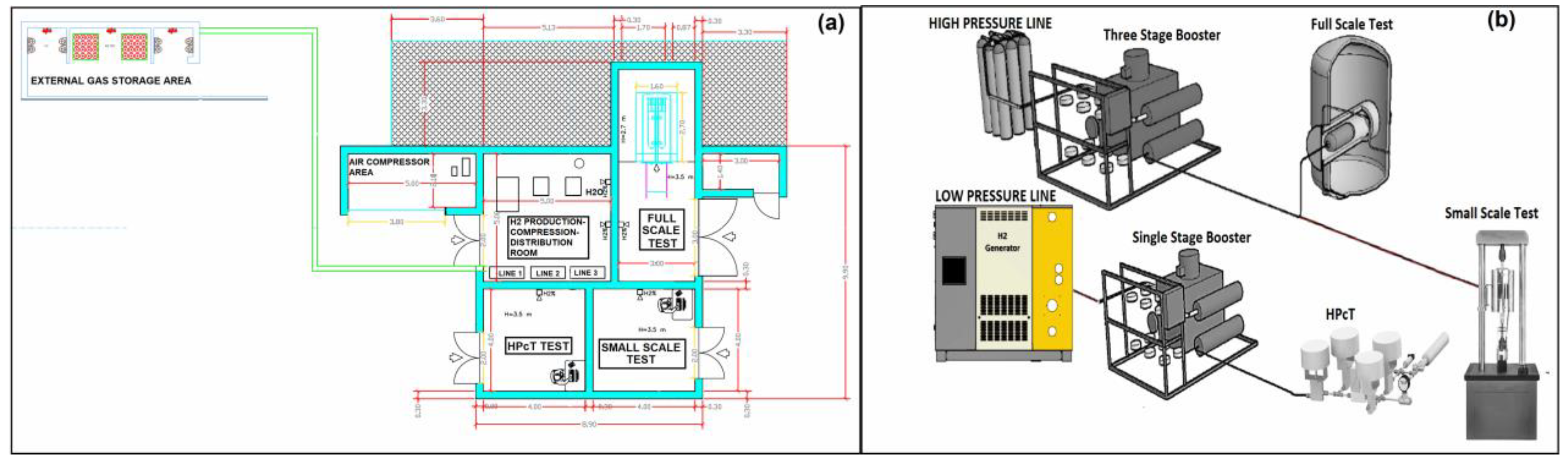
3. ΔH Test Lab
General Description
4. Materials and Methods
4.1. Materials
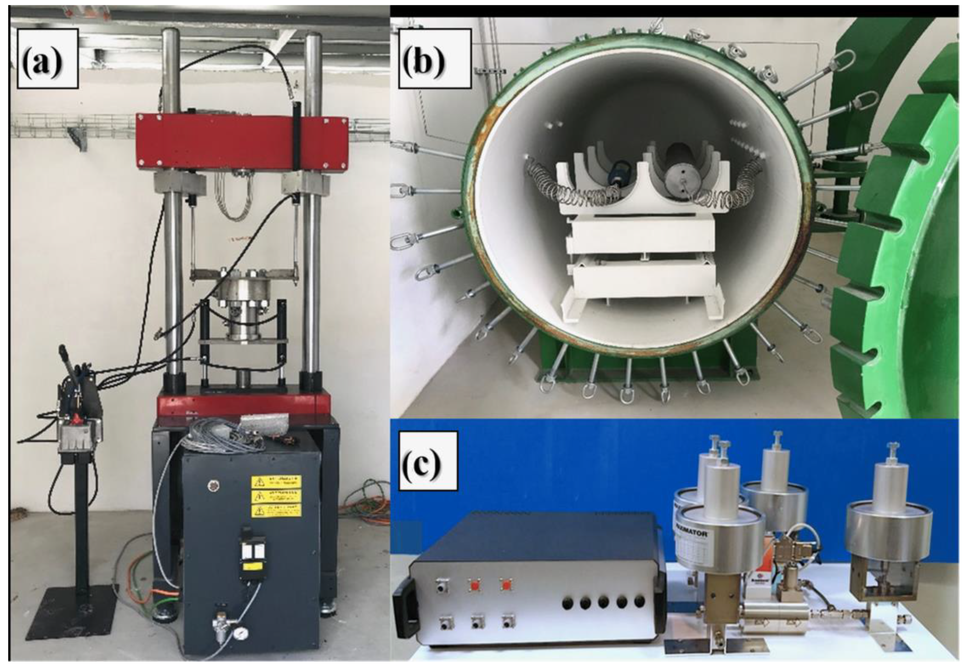
4.2. Testing
5. Results
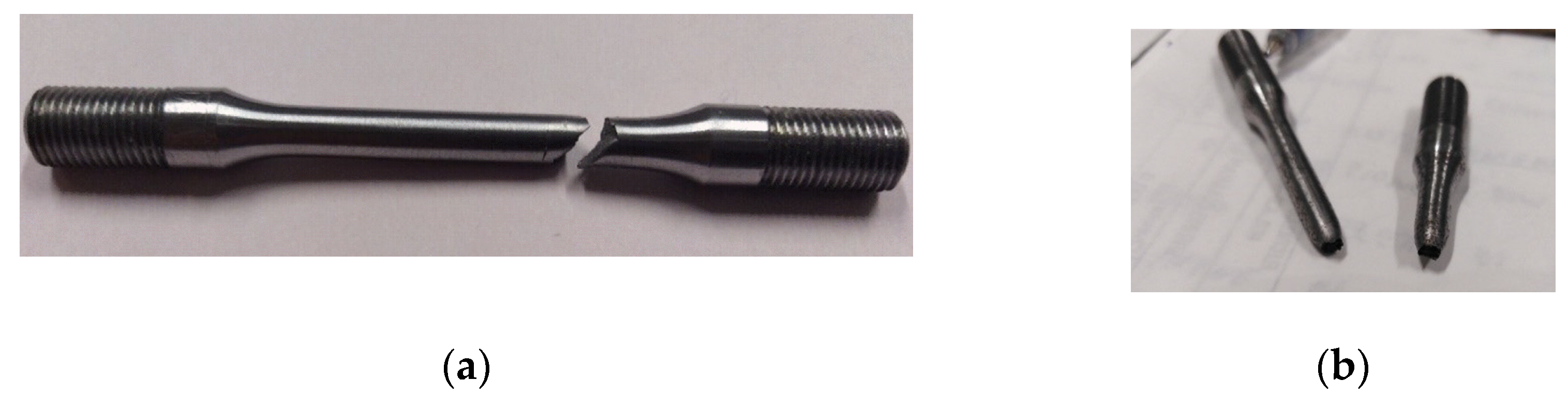
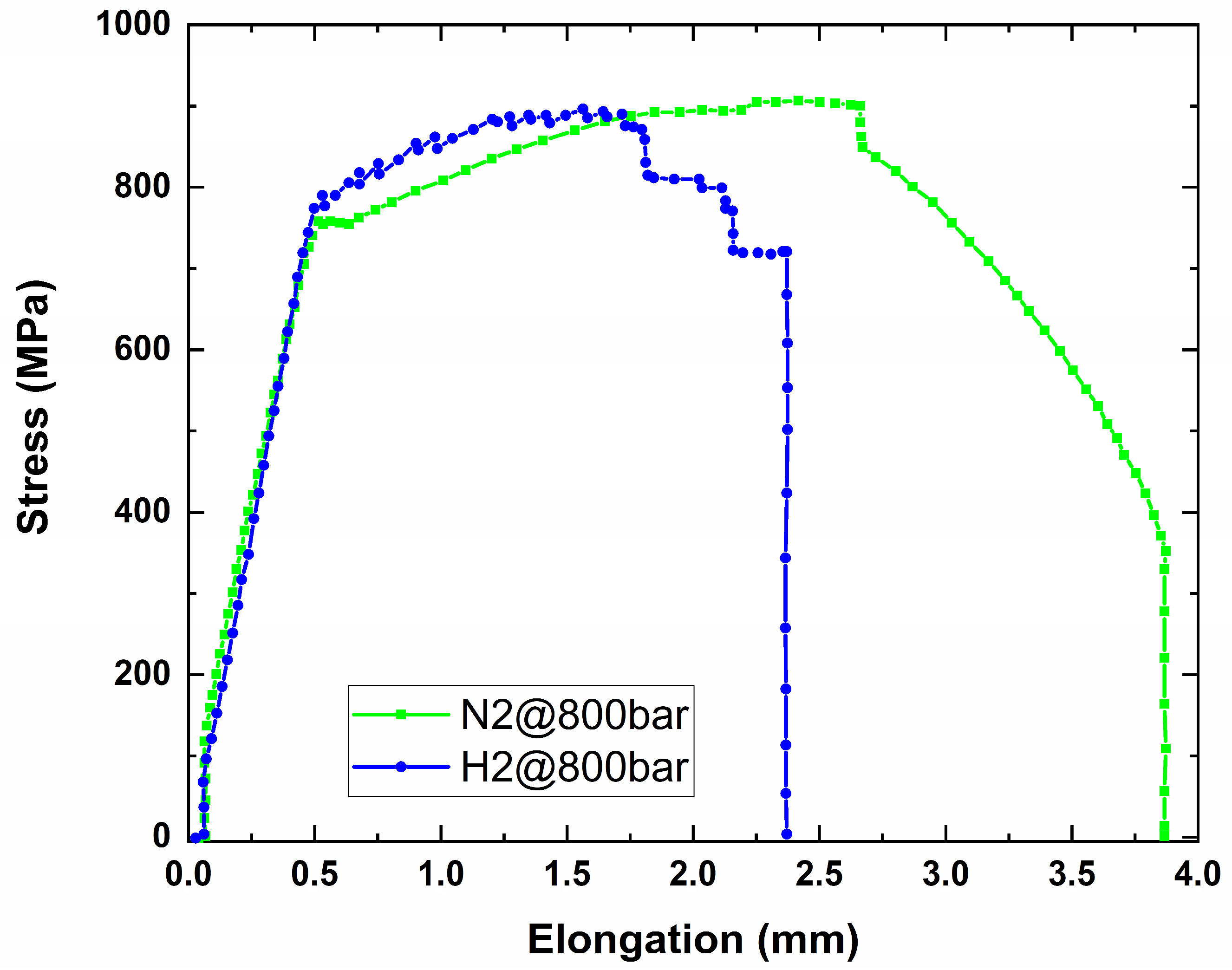
5.1. Slow Strain Rate Test
5.2. Full Scale Testing
5.3. Hydrogen Adsorption at High Pressures
6. Conclusions
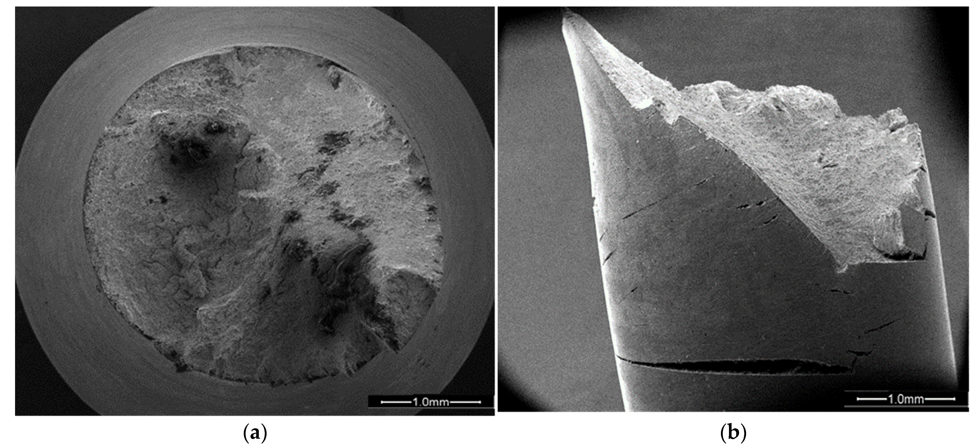
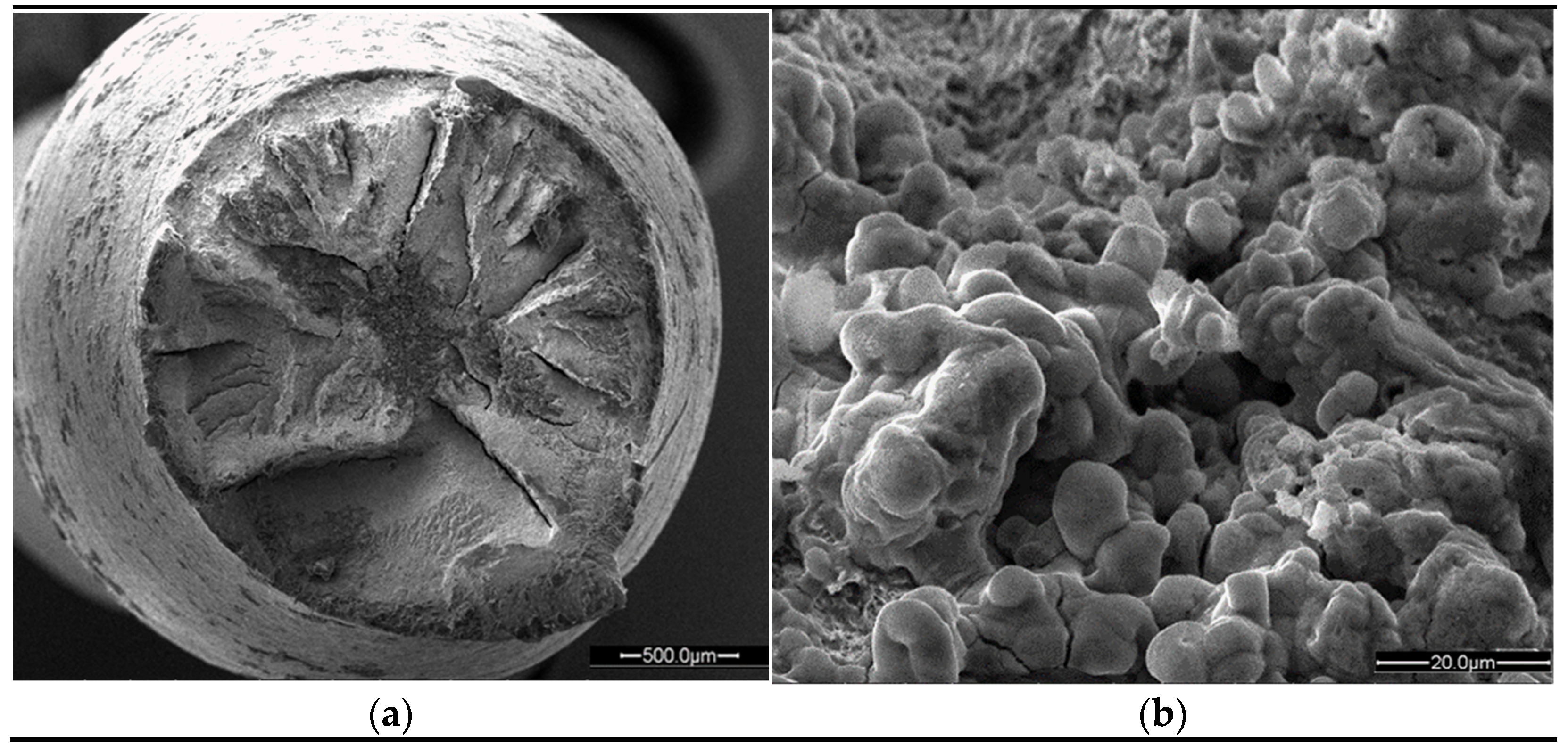
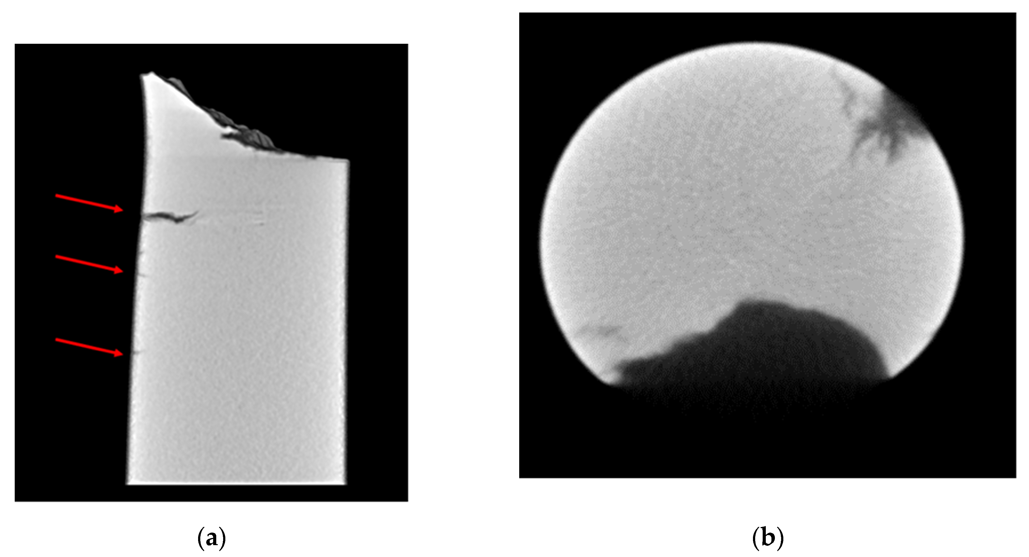
- The slow strain rate tests show an evident H2 effect on elongation and surface fracture of the material. The sample tested at 80 MPa in an inert environment has an elongation almost double with respect to the sample tested in H2. The scanning electron micrographs confirm a fracture surface characterized by a predominant brittle propagation mode (both transgranular and intergranular) and the presence of secondary crack for the sample tested in an H2 environment, such as highlighted by micro-tomography analysis.
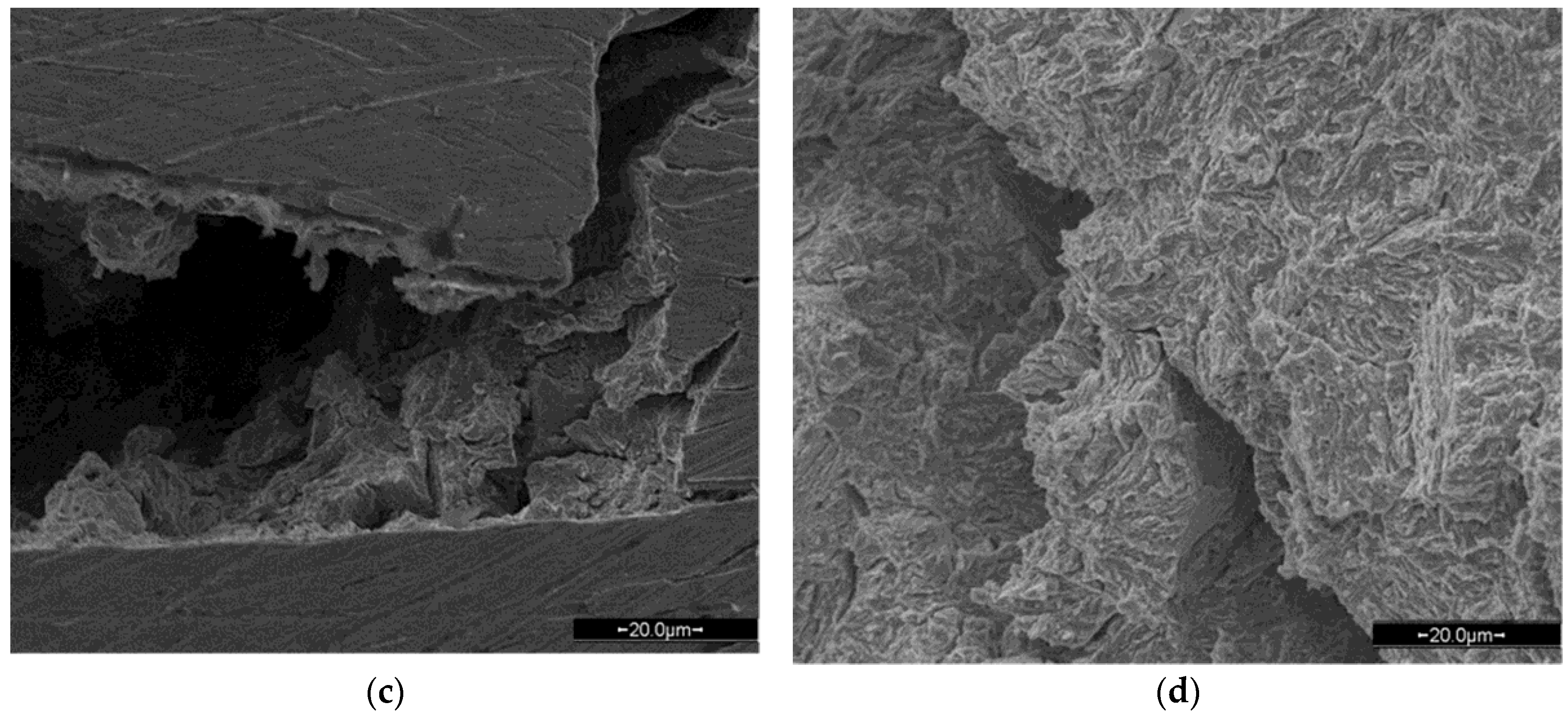
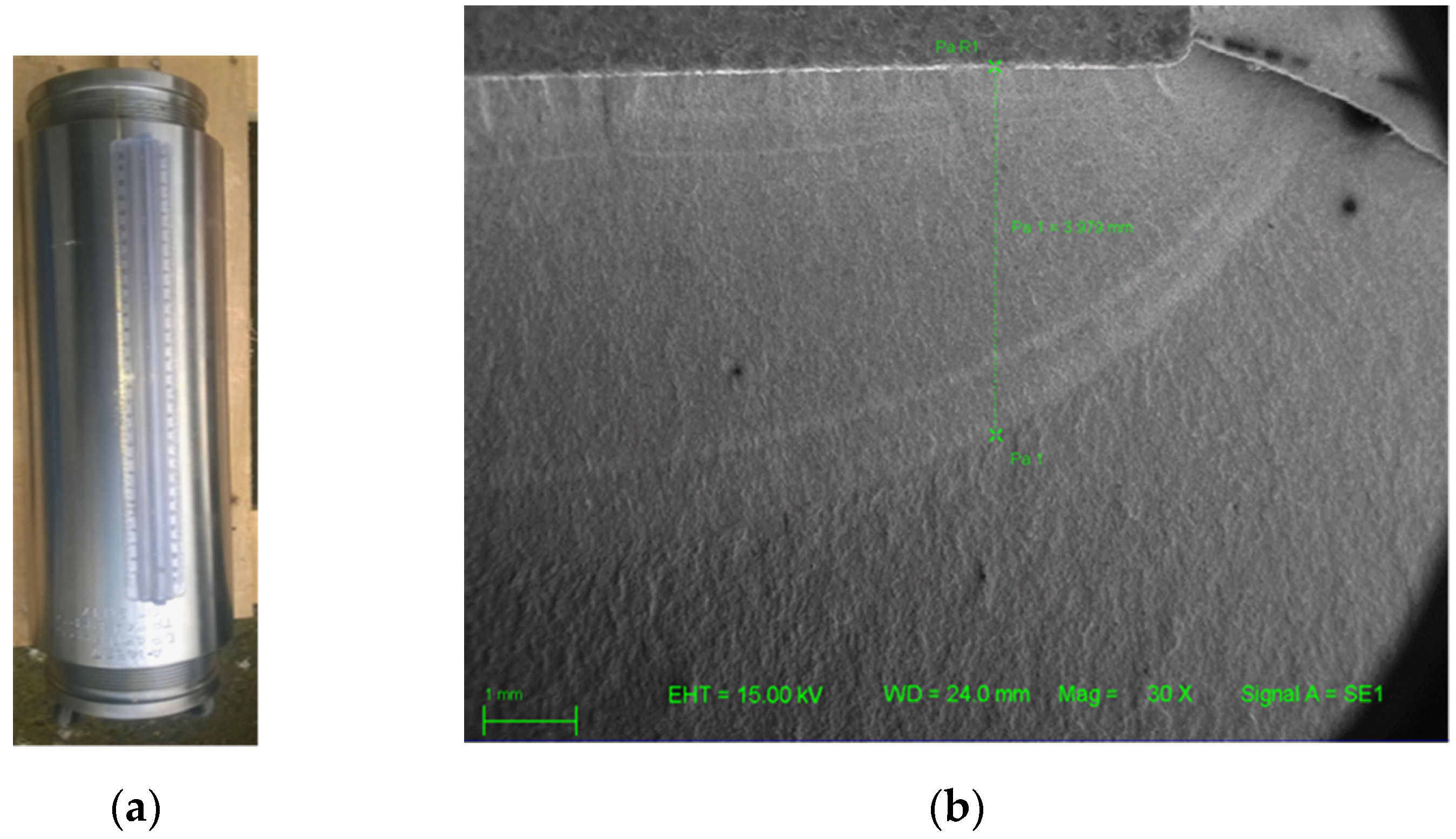
- The fatigue full-scale test performed in an H2 environment confirm the good performance of AISI 4145 alloy in a high-pressure regime at low pressure range. In fact, after being exposed to H2 pressure with a pre-machined notch, undergoing severe fatigue cycles, there is no evidence of fatigue crack propagation, as showed by scanning electron micrography.
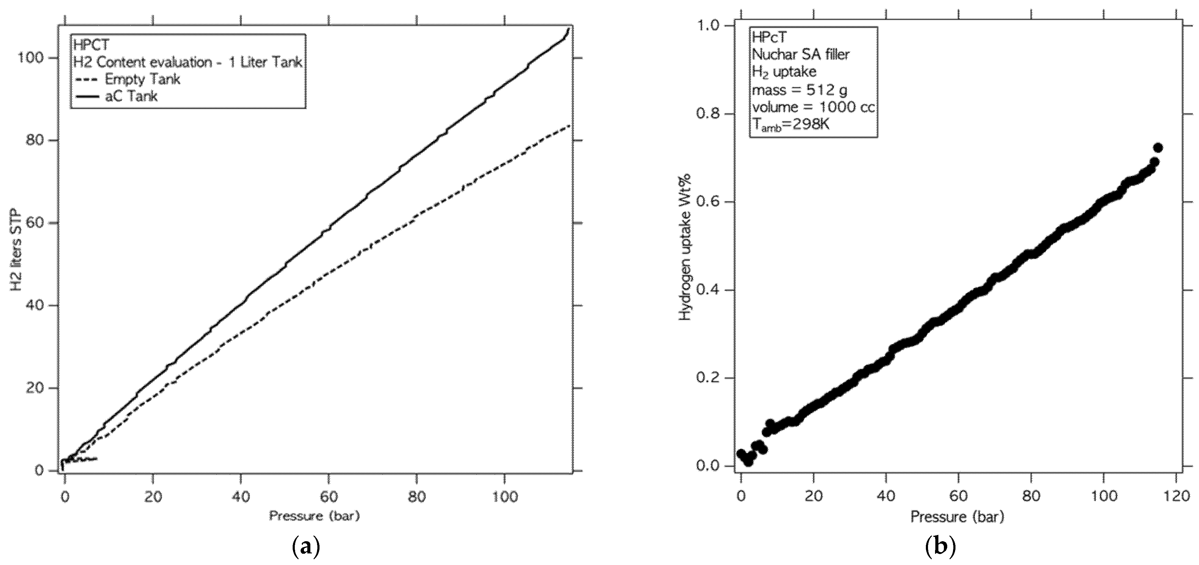
- The test on solid state materials shows as the presence of the adsorbed material results in a storage gain all over the pressure range with the highest increase, equal to 26%, observed at 12 MPa, which is in agreement with previous studies performed on NUCHAR SA in mg-scale quantities. This result highlight as the prototype is able to evaluate the adsorption capacity of solid-state materials on Kg-scale quantities obtaining results comparable to laboratory scale results.
Author Contributions
Funding
Institutional Review Board Statement
Informed Consent Statement
Data Availability Statement
Conflicts of Interest
References
- European Parliament. European Parliament Directive (EU) 2018/2001 of the European Parliament and of the Council of 11 December 2018 on the promotion of the use of energy from renewable sources (recast). Off. J. Eur. Union 2018, 2018, 82–207. [Google Scholar]
- Aneke, M.; Wang, M.E. Energy storage technologies and real-life applications—a state of the art review. Appl. Energy 2016, 179, 350–377. [Google Scholar] [CrossRef] [Green Version]
- Koohi-Fayegh, S.; Rosen, M.A. A review of energy storage types, applications and recent developments. J. Energy Storage 2020, 27, 101047. [Google Scholar] [CrossRef]
- IRENA International Renewable Energy Agency. Hydrogen from Renewable Power: Technology Outlook for the Energy Transition; International Renewable Energy Agency: Abu Dhabi, United Arab Emirates, 2018. [Google Scholar]
- Staffell, I.; Scamman, D.; Abad, A.V.; Balcombe, P.; Dodds, P.E.; Ekins, P. The role of hydrogen and fuel cells in the global energy system. Energy Environ. Sci. 2019, 12, 157E. [Google Scholar] [CrossRef] [Green Version]
- Glenk, G.; Reichelstein, S. Economics of converting renewable power to hydrogen. Nat. Energy 2019, 4, 216–222. [Google Scholar] [CrossRef]
- Maggio, G.; Nicita, A.; Squadrito, G. How the hydrogen production from RES could change energy and fuel markets: A review of recent literature. Int. J. Hydrog. Energy 2019, 44, 11371–11384. [Google Scholar] [CrossRef]
- Petreanu, I.; Dragan, M.; Badea, S.L. Fuel Cells: Alternative Energy Sources for Stationary, Mobile and Automotive Applications; Vizureanu, P., Ed.; IntechOpen: London, UK, 2020. [Google Scholar] [CrossRef]
- Jayakumar, A.; Chalmers, A.; Lie, T.T. Review of prospects for adoption of fuel cell electric vehicles in New Zealand. IET Electr. Syst. Transp. 2017, 7, 259–266. [Google Scholar] [CrossRef]
- Khzouz, M.I.; Gkanas, E.I. Hydrogen Technologies for Mobility and Stationary Applications: Hydrogen Production, Storage and Infrastructure Development, Renewable Energy—Resources, Challenges and Applications; Qubeissi, M.A., El-kharouf, A., Soyhan, H.S., Eds.; IntechOpen: London, UK, 2020. [Google Scholar] [CrossRef]
- Hydrogen Cars All Models at a Glance. Available online: https://h2.live/en/wasserstoffautos (accessed on 26 March 2021).
- Abdallaa, A.M.; Hossaina, S.; Nisfindya, O.B.; Azadd, A.T.; Dawood, M.; Azada, A.K. Hydrogen production, storage, transportation and key challenges with applications: A review. Energ. Convers. Manag. 2018, 165, 602–627. [Google Scholar] [CrossRef]
- IEA International Energy Agency. The Future of Hydrogen; International Energy Agency: Paris, France, 2019. [Google Scholar]
- Azzaro-Pantel, C. Hydrogen Supply Chain: Design, Deployment and Operation. 2018. Available online: https://0-search-ebscohost-com.brum.beds.ac.uk/login.aspx?direct=true&scope=site&db=nlebk&db=nlabk&AN=1649248 (accessed on 26 March 2021).
- Liu, W.; Sun, L.; Li, Z. Trends and future challenges in hydrogen production and storage research. Environ. Sci. Pollut. Res. 2020, 27, 31092–31104. [Google Scholar] [CrossRef]
- Peschel, A. Industrial Perspective on Hydrogen Purification, Compression, Storage, and Distribution. Fuel Cells 2020, 20. [Google Scholar] [CrossRef]
- Abe, J.O.; Popoola, A.P.I.; Ajenifuja, E.; Popoola, O.M. Hydrogen energy, economy and storage: Review and recommendation. Int. J. Hydrog. Energy 2019, 44, 15072–15086. [Google Scholar] [CrossRef]
- Klebanoff, L. Hydrogen Storage Technology: Materials and Applications, 1st ed.; CRC Press: New York, NY, USA, 2016. [Google Scholar]
- Zhang, S.; Lee, L.H.; Sun, Y.; Liu, Y. Materials for Hydrogen Mobile Storage Applications. IOP Conf. Ser. Earth Environ. Sci. 2021, 632, 052087. [Google Scholar] [CrossRef]
- Zuttel, A. Hydrogen storage methods. Naturwissenschaften 2004, 91, 157–172. [Google Scholar] [CrossRef]
- Pethaiah, S.S.; Sadasivuni, K.K.; Jayakumar, A.; Ponnamma, D.; Tiwary, C.S.B.; Sasikumar, G. Methanol Electrolysis for Hydrogen Production Using Polymer Electrolyte Membrane: A Mini-Review. Energies 2020, 13, 5879. [Google Scholar] [CrossRef]
- Boateng, E.; Chen, A. Recent advances in nanomaterial-based solid-state hydrogen storage. Mater. Today Adv. 2020, 6, 100022. [Google Scholar] [CrossRef]
- Modisha, P.M.; Ouma, C.N.M.; Garidzirai, R.; Wasserscheid, P.; Bessarabov, D. The Prospect of Hydrogen Storage Using Liquid Organic Hydrogen Carriers. Energy Fuels 2019, 33, 2778–2796. [Google Scholar] [CrossRef]
- Robertson, I.M.; Sofronis, P.; Nagao, A.; Martin, M.L.; Wang, S.; Gross, D.W. Hydrogen Embrittlement Understood. Metall. Materi. Trans. B 2015, 46, 10851103. [Google Scholar] [CrossRef]
- Eguch, K.; Burnett, T.L.; Engelberg, D.L. X-Ray tomographic characterisation of pitting corrosion in lean duplex stainless steel. Corros. Sci. 2020, 165, 108406. [Google Scholar] [CrossRef]
- Wu, K.; Ito, K.; Shinozaki, I.; Chivavibul, P.; Enoki, M. A Comparative Study of Localized Corrosion and Stress Corrosion Cracking of 13Cr Martensitic Stainless Steel Using Acoustic Emission and X-ray Computed Tomography. Materials 2019, 12, 2569. [Google Scholar] [CrossRef] [Green Version]
- Laquai, R.; Schaupp, T.; Müller, B.R.; Griesche, A.; Kupsch, A.; Lange, A. 3D Crack Analysis in Hydrogen Charged Lean Duplex Stainless Steel with Synchrotron Refraction CT. In Proceedings of the 19th World Conference on Non-Destructive Testing 2016, Munich, Germany, 13–17 June 2016. [Google Scholar]
- Dong, Z.; Zhang, X.; Shi, W.; Zhou, H.; Lei, H.; Liang, J. Study of Size Effect on Microstructure and Mechanical Properties of AlSi10Mg Samples Made by Selective Laser Melting. Materials 2018, 11, 2463. [Google Scholar] [CrossRef] [Green Version]
- Rouquerol, J.; Avnir, D.; Fairbridge, C.W.; Everett, D.H.; Haynes, J.M.; Pernicone, N.; Ramsay, J.D.F.; Sing, K.S.W.; Unger, K.K. Recommendations for the characterization of porous solids (Technical Report). Pure Appl. Chem. 1994, 1739. [Google Scholar] [CrossRef]
- Rouquerol, F.; Rouquerol, J.; Sing, K. Adsorption by Powders and Porous Solids Principles, Methodology and Applications. Sci. Direct 2012, 2, 646. [Google Scholar]
- Zuttel, A. Materials for hydrogen storage. Mater. Today 2003, 6, 24–33. [Google Scholar] [CrossRef]
- Barthelemy, H.; Weber, M.; Barbier, F. Hydrogen storage: Recent improvements and industrial perspectives. Int. J. Hydrog. Energy 2017, 42, 7254–7262. [Google Scholar] [CrossRef]
- Rivard, E.; Trudeau, M.; Zaghib, K. Hydrogen Storage for Mobility: A Review. Materials 2019, 12, 1973. [Google Scholar] [CrossRef] [Green Version]
- Nagumo, M. Fundamental of Hydrogen Embrittlement; Springer: Singapore, 2016. [Google Scholar]
- Dwivedi, S.K.; Vishwakarma, M. Hydrogen embrittlement in different materials: A Review. Int. J. Hydrog. Energy 2018, 43, 21603–21616. [Google Scholar] [CrossRef]
- Atrens, A.; Liu, Q.; Tapia-Bastidas, C.; Gray, E.; Irwanto, B.; Venezuela, J.; Liu, Q. Influence of Hydrogen on Steel Components for Clean Energy. Corros. Mater. Degrad. 2020, 1, 2. [Google Scholar] [CrossRef] [Green Version]
- Li, M.; Bai, Y.; Zhang, C.; Song, Y.; Jiang, S.; Grouset, D.; Zhang, M. Review on the research of hydrogen storage system fast refueling in fuel cell vehicle. Int. J. Hydrog. Energy 2019, 44, 10677–10693. [Google Scholar] [CrossRef] [Green Version]
- Yanxing, Z.; Maoqiong, G.; Yuan, Z.; Xueqiang, D.; Jun, S. Thermodynamics analysis of hydrogen storage based on compressed gaseous hydrogen, liquid hydrogen and cryo-compressed hydrogen. Int. J. Hydrog. Energy 2019, 44, 16833–16840. [Google Scholar] [CrossRef]
- Langmi, H.W.; Ren, J.; North, B.; Mathe, M.; Bessarabov, D. Hydrogen Storage in Metal-Organic Frameworks: A Review. Electrochim. Acta 2014, 128, 368–392. [Google Scholar] [CrossRef]
- Anderson, P.A. Storage of hydrogen in zeolites. In Solid-State Hydrogen Storage; Woodhead Publishing: Cambridge, UK, 2008; pp. 223–260. [Google Scholar]
- Von Colbe, B.J.; Ares, J.R.; Barale, J.; Baricco, M.; Buckley, C.; Capurso, G.; Gallandat, N.; Grant, D.M.; Guzik, M.N.; Jacob, I.; et al. Application of hydrides in hydrogen storage and compression: Achievements, outlook and perspectives. Int. J. Hydrog. Energy 2019, 44, 7780–7808. [Google Scholar] [CrossRef]
- Tian, M.; Rochat, S.; Polak-Kraśna, K.; Holyfield, L.T.; Burrows, A.D.; Bowen, C.R.; Bowen, C.R.; Mays, T.J. Nanoporous polymer-based composites for enhanced hydrogen storage. Adsorption 2019, 25, 889–901. [Google Scholar] [CrossRef] [Green Version]
- Liu, B.; Xiao, J.; Xu, L.; Yao, Y.; Costa, B.F.O.; Domingos, V.F.; Ribeiro, E.S.; Shi, F.N.; Zhou, K.; Su, J.; et al. Gelatin-assisted sol–gel derived TiO2 microspheres for hydrogen storage. Int. J. Hydrog. Energy 2015, 40, 4945–4950. [Google Scholar] [CrossRef]
- Stelitano, S.; Conte, G.; Policicchio, A.; Aloise, A.; Desiderio, G.; Agostino, R.G. Pinecone-Derived Activated Carbons as an Effective Medium for Hydrogen Storage. Energies 2020, 13, 2237. [Google Scholar] [CrossRef]
- Hirscher, M.; Yartys, V.A.; Baricco, M.; von Colbe, J.B.; Blanchard, D.; Bowman, R.C.; Broom, D.P.; Buckley, C.E.; Chang, F.; Chen, P.; et al. Materials for hydrogen-based energy storage—Past, recent progress and future outlook. J. Alloy Compd. 2020, 827. [Google Scholar] [CrossRef]
- Niaz, S.; Manzoor, T.; Pandith, A.H. Hydrogen storage: Materials, methods and perspectives. Renew. Sust. Energy Rev. 2015, 50, 457–469. [Google Scholar] [CrossRef]
- Ren, J.; Musyok, N.M.; Langmi, H.W.; Mathe, M.; Liao, S. Current research trends and perspectives on materials-based hydrogen storage solutions: A critical review. Int. J. Hydrog. Energy 2017, 42, 289–311. [Google Scholar] [CrossRef]
- EOMAT Sistemi e Materiali Innovativi per la Produzione e Stoccaggio di Energia Rinnovabile PON03PE_00092_1. Available online: http://www.ponrec.it/open-data/progetti/scheda-progetto?ProgettoID=7350 (accessed on 2 April 2021).
- Minuto, F.D.; Policicchio, A.; Aloise, A.; Agostino, R.G. Liquid-like hydrogen in the micropores of commercial activated carbons. Int. J. Hydrog. Energy 2015, 40, 14562–14572. [Google Scholar] [CrossRef]
- Ugiansky, G.M.; Payer, J.H. ASTM STP 665: Stress Corrosion Cracking: The Slow Strain-Rate Technique; ASTM International: West Conshohocken, PA, USA, 1979. [Google Scholar]
- Kane, R.D. Slow Strain Rate Testing for the Evaluation of Environmentally Induced Cracking: Research and Engineering Applications; ASTM International: West Conshohocken, PA, USA, 1993. [Google Scholar]
- Martinez-Paneda, E.; Harris, Z.D.; Fuentes-Alonso, S.; Scully, J.R.; Burns, J.T. On the suitability of slow strain rate tensile testing for assessing hydrogen embrittlement susceptibility. Corros. Sci. 2020, 163, 108291. [Google Scholar] [CrossRef] [Green Version]
- Matsunaga, H. Slow strain rate tensile and fatigue properties of Cr-Mo and carbon steels in a 115 MPa hydrogen gas atmosphere. Int. J. Hydrog. Energy 2015, 40, 5739–5748. [Google Scholar] [CrossRef]
- Briottet, L.; Moro, I.; Lemoine, P. Quantifying the Hydrogen Embrittlement of Pipe Steels for Safety Considerations. Int. J. Hydrog. Energy 2012, 37, 17616–17623. [Google Scholar] [CrossRef]
- Yamabe, J.; Takakuwa, O.; Matsunaga, H.; Itoga, H.; Matsuoka, S. Hydrogen diffusivity and tensile-ductility loss of solution-treated austenitic stainless steels with external and internal hydrogen. Int. J. Hydrog. Energy 2017, 42, 13289–13299. [Google Scholar] [CrossRef]
- Matsuoka, S.; Yamabe, J.; Matsunaga, H. Criteria for determining hydrogen compatibility and the mechanisms for hydrogen-assisted, surface crack growth in austenitic stainless steels. Eng. Fract. Mech. 2016, 153, 103–127. [Google Scholar] [CrossRef]
- Matsuoka, S.; Yamabe, J.; Matsunaga, H. Mechanism of Hydrogen-Assisted Surface Crack Growth of Austenitic Stainless Steels in Slow Strain Rate Tensile Test. In Proceedings of the ASME Pressure Vessels and Piping Conference PVP2016-63394, Vancouver, BC, Canada, 17–21 July 2016. [Google Scholar] [CrossRef]
- San Marchi, C.; Dedrick, D.E.; Van Blarigan, P.; Somerday, B.P.; Nibur, K. Pressure Cycling of Type 1 Pressure Vessels with Gaseous Hydrogen; ICHS: San Francisco, CA, USA, 2011. [Google Scholar]
- San Marchi, C.; Harris, A.; Yip, M.; Somerday, B.P.; Nibur, K. Pressure Cycling of Steel Pressure Vessels with Gaseous Hydrogen. In Proceedings of the ASME Pressure Vessels & Piping Conference PVP2012, Toronto, ON, Canada, 15–19 July 2012; pp. 835–844. [Google Scholar] [CrossRef]
- Yamabe, J.; Itoga, H.; Awane, T.; Matsunaga, H.; Hamada, S.; Matsuoka, S. Fatigue-life and Leak-Before-Break Assessments of Cr-Mo Steel Pressure Vessels with High—Pressure Gaseous Hydrogen. In Proceedings of the ASME 2014 Pressure Vessels & Piping Conference PVP2014, Anaheim, CA, USA, 20–24 July 2014; p. 28604. [Google Scholar] [CrossRef]
- Yamabe, J.; Itoga, H.; Awane, T.; Matsuo, T.; Matsunaga, H.; Matsuoka, S. Pressure cycle testing of Cr-Mo steel pressure vessels subjected to gaseous hydrogen. J. Press. Vessel Technol. 2015, 138, 011401. [Google Scholar] [CrossRef]
- De Miguel, N.; Acosta, B.; Moretto, P.; Briottet, L.; Bortot, P.; Mecozzi, E. Hydrogen enhanced fatigue in full scale metallic vessel tests—Results from the MATHRYCE project. Int. J. Hydrog. Energy 2017, 42, 13777–13788. [Google Scholar] [CrossRef]


| Storage Method | Gravimetric Capacity [wt%] | Volumetric Capacity [kgH2/m3] | T [K] | P [MPa] | Pros | Cons |
|---|---|---|---|---|---|---|
| CGH2 | 6 | < 40 | RT | 70 | High efficiency, convenient, mature technology | Expensive cylinder and the immature technology of fast filling. |
| lH2 | 8 | 70 | 20 | 0.1 | High liquid density and storage efficiency | Large consume of energy and time, low temperature, boil-off |
| CcH2 | ~5 | ~40 | 20 | 30 | Low boil-off | High costs |
| SSMs -Phys | 2 | 20 | 77 | 10 | Highly porous, high uptake of H2 and specific surface areas, fully reversible | Very low storage temperature |
| SSMs -Chem | 15 | 150 | RT | 2 | High safety, high purity of H2 good reversible cycle performance, large volume of H2 density | Absorbing impurities, reducing the H2 capacity and the lifetime of tank |
Publisher’s Note: MDPI stays neutral with regard to jurisdictional claims in published maps and institutional affiliations. |
© 2021 by the authors. Licensee MDPI, Basel, Switzerland. This article is an open access article distributed under the terms and conditions of the Creative Commons Attribution (CC BY) license (https://creativecommons.org/licenses/by/4.0/).
Share and Cite
Stelitano, S.; Rullo, A.; Piredda, L.; Mecozzi, E.; Di Vito, L.; Agostino, R.G.; Filosa, R.; Formoso, V.; Conte, G.; Policicchio, A. The Deltah Lab, a New Multidisciplinary European Facility to Support the H2 Distribution & Storage Economy. Appl. Sci. 2021, 11, 3272. https://0-doi-org.brum.beds.ac.uk/10.3390/app11073272
Stelitano S, Rullo A, Piredda L, Mecozzi E, Di Vito L, Agostino RG, Filosa R, Formoso V, Conte G, Policicchio A. The Deltah Lab, a New Multidisciplinary European Facility to Support the H2 Distribution & Storage Economy. Applied Sciences. 2021; 11(7):3272. https://0-doi-org.brum.beds.ac.uk/10.3390/app11073272
Chicago/Turabian StyleStelitano, Sara, Alberto Rullo, Luigi Piredda, Elisabetta Mecozzi, Luigi Di Vito, Raffaele Giuseppe Agostino, Raffaele Filosa, Vincenzo Formoso, Giuseppe Conte, and Alfonso Policicchio. 2021. "The Deltah Lab, a New Multidisciplinary European Facility to Support the H2 Distribution & Storage Economy" Applied Sciences 11, no. 7: 3272. https://0-doi-org.brum.beds.ac.uk/10.3390/app11073272