Experimental/Numerical Evaluation of Steel Trapezoidal Corrugated Infill Panels with an Opening

1
Department of Civil Engineering, Sharif University of Technology, International Campus-Kish Island, Kish Island 79417-76655, Iran
2
Department of Civil Engineering, Sharif University of Technology, Tehran 145888-9694, Iran
*
Author to whom correspondence should be addressed.
Appl. Sci. 2021, 11(7), 3275; https://0-doi-org.brum.beds.ac.uk/10.3390/app11073275
Submission received: 27 February 2021
/
Revised: 29 March 2021
/
Accepted: 30 March 2021
/
Published: 6 April 2021
(This article belongs to the Section Civil Engineering)
Abstract
:This paper investigates the influence of an opening in the infill steel plate on the behavior of steel trapezoidal corrugated infill panels. Two specimens of steel trapezoidal corrugated shear walls were constructed and tested under cyclic loading. One specimen had a single rectangular opening, while the other one had two rectangular openings. In addition, the percentage of opening in both specimens was 18%. The initial stiffness, ultimate strength, ductility ratio and energy dissipation capacity of the two tested specimens are compared to a specimen without opening. The experimental results indicate that the existence of an opening has the greatest effect on the initial stiffness of the corrugated steel infill panels. In addition, the experimental results reveal that the structural performance of the specimen with two openings is improved in some areas compared to the specimen with one opening. To that end, the energy dissipation capacity of the specimen with two openings is obtained larger than the specimen with one opening. Furthermore, a number of numerical analyses were performed. The numerical results show that with increasing the thickness of the infill plate or using stiffeners around the opening, the ultimate strength of a corrugated steel infill panel with an opening can be equal to or even more than the ultimate strength of that panel without an opening.
1. Introduction
One type of lateral load resisting system used in the construction of new buildings or retrofitting of existing buildings is the steel shear wall. In this system, steel plates are attached to adjacent boundary elements (beams and columns). High stiffness, enhanced strength, great ductility, considerable energy absorption capability and stable hysteretic behavior are the specific characteristics of steel infill panels (SIPs) [1,2,3,4]. The initial design procedure of SIPs has led to the use of thick or heavily stiffened steel plates to prevent elastic buckling. Thereafter, it was shown that the ultimate strength capacity of SIPs does not pertain to their buckling load, and considerable post-buckling strength was reported for thin SIPs. The in-plane shear load-resisting mechanism alters to a diagonal tension field at the buckling point of SIPs, and significant strength is obtained from the post-buckling tension field action. Moreover, the buckling strength of SIPs can increase using trapezoidal corrugated plates, which consist of the plane and inclined subpanels.
The performance of corrugated steel infill panels (CSIPs) has been considered in past studies. Tong and Guo [5] presented formulas to determine the buckling load of CSIPs with vertical stiffeners. The accuracy of the proposed formulas was confirmed via the good agreement obtained between the results of these formulas and the finite element numerical results. Hossienzadeh et al. [6] studied the linear shear buckling analysis of simple and corrugated panels using numerical modeling. The numerical results were obtained close to those theoretical relations that consider a combination of global buckling and local buckling along with the shear yielding stress (interaction buckling). Gholizadeh and Yadollahi [7] considered the performance of simple and corrugated steel infill panels due to monotonic loading numerically. The models with corrugated panels had more ultimate bearing capacity, ductility and energy absorption capacity than the models with the simple panels. Hossienzadeh et al. [8] tested three specimens of one-story, single-bay CSIPs under cyclic loading. As reported, the stiffness, energy absorption capacity and ultimate strength of corrugated plates decreased with increasing the corrugation angle. In addition, the cyclic behavior of trapezoidal corrugated steel infill panels was studied experimentally by Emami et al. [9]. This study reported that the initial stiffness, ductility and energy absorption capacity of corrugated models were 20%, 40% and 52% larger compared to the flat unstiffened model, respectively. Moreover, the performance of CSIPs under cyclic loading was considered in some other studies [10,11,12,13,14,15,16]. Meanwhile, the performance of multi-story SIPs was discussed in previous studies [17,18,19,20,21,22].
Providing an opening in SIPs is sometimes necessary because of architectural restrictions. The introduction of an opening to steel panels could affect their performance. Moradi et al. [23] performed finite element analyses and utilized the FEM results to develop an artificial neural network to predict the behavior of SIPs with an opening. Ahmad Khan and Srivastava [24] investigated the performance of SIPs with an opening. It was observed that the opening location affects the strength and stiffness degradation of unstiffened SIPs with an opening. Hosseinzadeh and Tehranizadeh [25] analyzed SIPs with and without stiffened large rectangular openings. The results of their numerical analyses indicated that the geometry and location of stiffened openings do not directly influence the strength of SIPs, and the main concern should be paid to the design of local boundary elements around the stiffened openings. Alavi and Nateghi [26] tested three steel infill panel specimens under the influence of cyclic loading. It was found that the structural characteristics of the specimen with a central perforation and diagonal stiffeners are close to the characteristics of the solid unstiffened specimen. The effect of opening on the behavior of CSIPs was considered in previous studies numerically [27,28,29,30,31,32], but no experimental specimen of CSIPs with an opening has been tested so far. Furthermore, the effect of using two openings instead of one opening despite the same opening percentage was not considered.
In this study, the cycling testing of two trapezoidally vertical corrugated steel shear walls was conducted. One specimen had a single opening, and the other one had two openings. The results of tested specimens are compared to a specimen without opening tested by Emami et al. [9]. In addition, a number of numerical analyses were performed using a general-purpose nonlinear program to consider the effect of the infill plate thickness and the use of stiffeners around the opening on the performance of CSIPs with an opening.
2. Test Program
2.1. Specimens Type
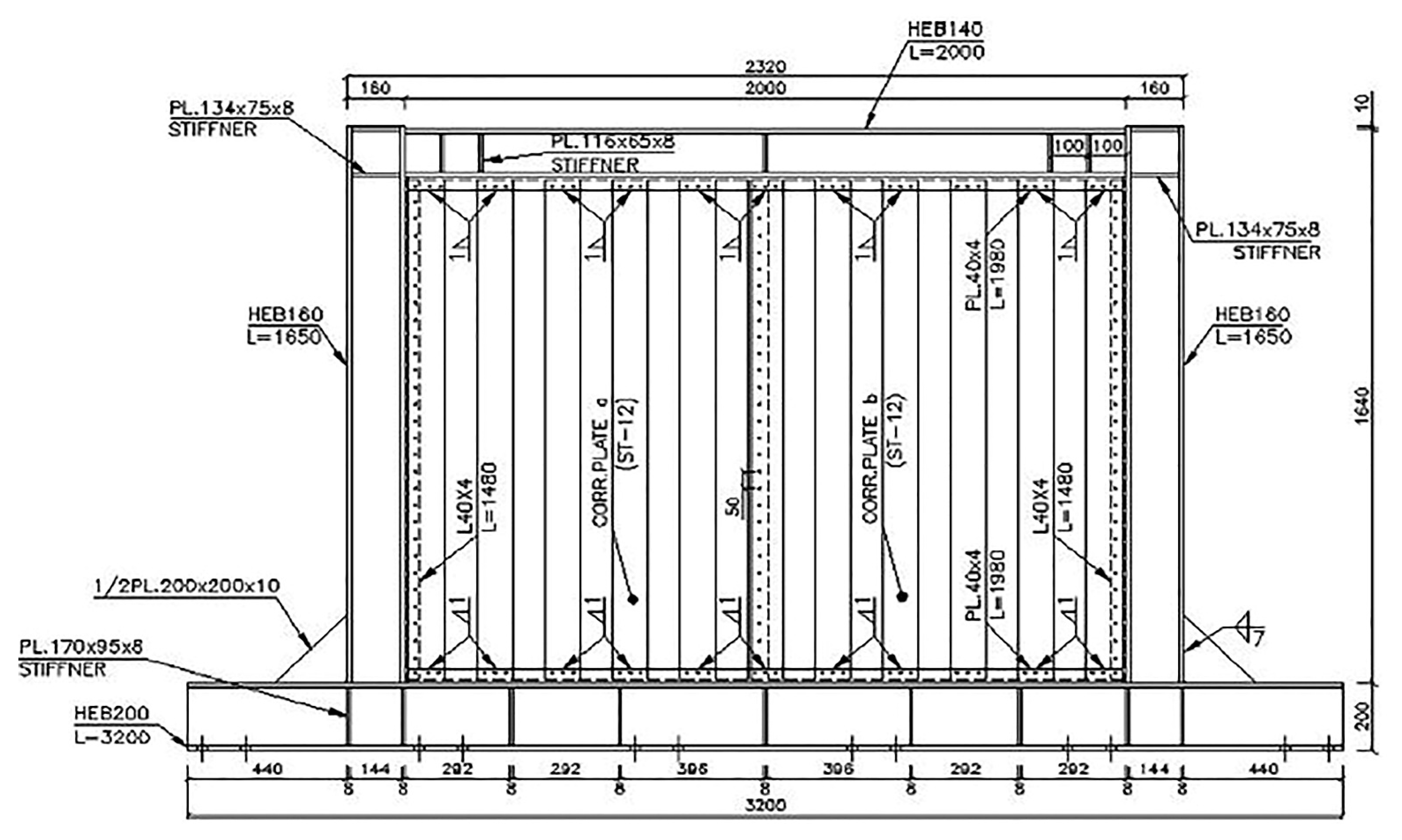
Two half-scale trapezoidally vertical corrugated steel shear walls were constructed. Both specimens had a single bay and one story. The first specimen had a single rectangular opening, while the second specimen had two rectangular openings. The optimal location of the opening in the first specimen was chosen based on the work of Farzampour et al. [28]. Furthermore, the area of the single opening in the first model, as well as the area of two openings in the second model, was equivalent to 18% of the panel area. Figure 1 and Figure 2 show the details of two specimens. All dimensions, the corrugated infill plate, boundary frame and connections of both specimens were similar to the corrugated specimen designed and tested by Emami et al. [9] in order to compare two cases of CSIPs with and without opening. Figure 3 indicates a drawing of the specimen tested by Emami et al. [9].
In each specimen and similar to Emami et al. [9], fillet welds and complete penetration groove welds were used for beam-to-column connections to achieve the moment-resisting connections. In each specimen, the thickness of the corrugated plate was equal to 1.25 mm. The connection of the panel to the boundary frame was developed using fish plates along with welds with an effective thickness of 1 mm and A325 bolts. Figure 4 indicates the details of connections. Because of limitations in the size of constructed thin steel plates, two infill steel plates were used and joined to each other in the middle span of the infill shear panel in each specimen. The edges of two infill steel plates had a 40 mm overlap and were connected by the combination of weld and bolt. Moreover, each specimen was attached to the laboratory rigid steel floor using M24 bolts (see Figure 5).
2.2. Material Properties
2.3. Test Setup
The test setup of the first and second specimens is shown in Figure 6 and Figure 7, respectively. In each specimen, two lateral support beams were used at both sides of the top beam to avoid the out-of-plane buckling. The section of lateral support beams was HPE-160. In addition, the support beams were connected to the triangular support frames at their ends.
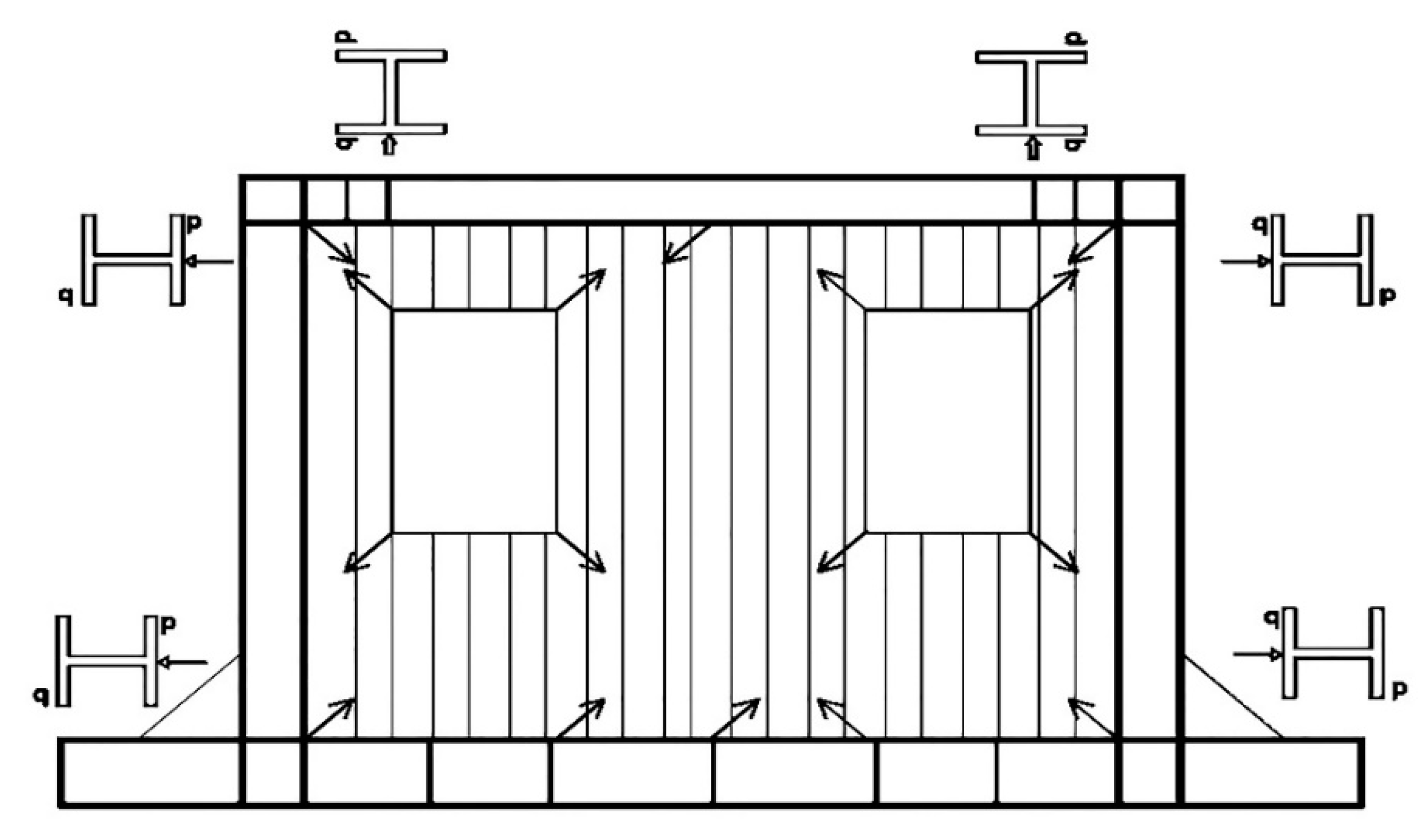
Linear variable differential transformers (LVDTs) were utilized to measure displacements. Four LVDTs were located on the bottom beam in each specimen to take into account the possible slip and rotation of the bottom beam. Two LVDTs were situated at the left and right top of each specimen, where the obtained mean displacement was considered as the amount of displacement. In addition, axial strain gauges were used to measure the strains induced in the beams and columns, while the strains induced in the steel plate were measured using triaxial strain gauges. Figure 8 and Figure 9 show the location of strain gauges used during the test of the first and second specimens, respectively. The value of the applied load was measured using two load cells.
2.4. Loading Program
Similar to Emami et al. [9], displacement-controlled loading in the absence of gravity loads was applied using the horizontal displacement sequence with increasing and decaying amplitudes at the top of specimens. The sequential displacements were implemented according to the AC154 protocol [34]. Of course, like Emami et al. [9], some changes were applied to the loading procedure described in the AC154 in order to accurately evaluate the elastic behavior along with the buckling of specimens. These changes consisted of applying the initial displacement cycles lower than 25% of the approximate elastic displacement (AED) and repeating each amplitude for two cycles rather than three cycles. Similar to Emami et al. [9], the AED value was chosen to be 20 mm. Loading was terminated when the displacement amplitude equaled 100 mm.
3. Results
3.1. Behavior of Specimen 1
The infill shear plate behaved elastically during the first four cycles with 1, 2, 3 and 4 mm displacements, respectively. Buckling of the shear plate was detected in cycle 5 with 6 mm displacement and 0.38% drift angle. Distortion of the shear plate was observed first on the left side of the panel near the top of the opening and then in the bottom right corner in the direction of the large diameter of the panel during cycles 5 and 6. In cycles 7 and 8, new distortions were developed in the direction of the other diameter of the shear panel.
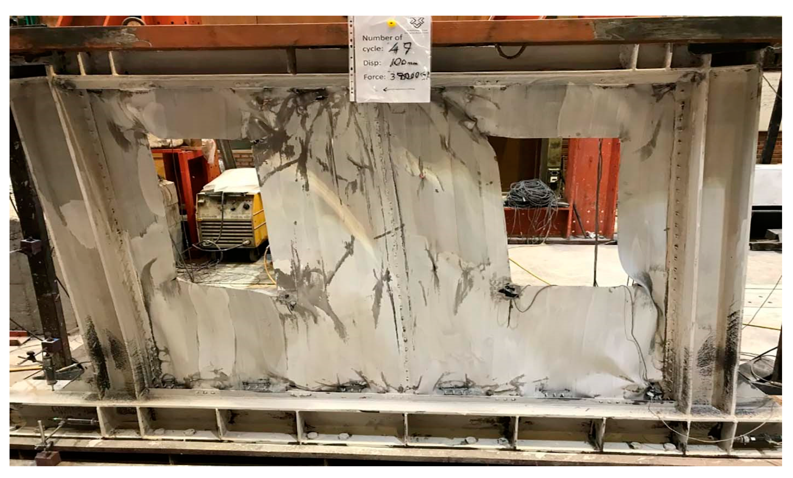
The first tear was seen on the left side near the top of the opening in cycle 15 with 25 mm displacement and 1.59% drift angle. During cycle 19 with 30 mm displacement and 1.91% drift angle, the second tear was monitored in the top right corner. The third and fourth tears were detected during cycles 23 and 25 with the same displacement of 35 mm and drift angle of 2.22% in the top and bottom left corners, respectively. By continuing the loading, the number of tears and their dimensions both increased, and cracks were developed in welded connections, especially the welded connections of the infill plate to the beams and columns. In cycle 39 with 70 mm displacement and 4.45% drift angle, the shear force increased to 385 kN, which was the maximum recorded shear force during the loading of this specimen. Yielding of the columns’ external flange was clearly observed at their bottom end in cycle 39. Moreover, during cycles 43–46 with 80 mm displacement and 5.12% drift angle, conditions of the columns at their top end, as well as conditions of the top beam at the points of its connections to the columns, indicated yielding clearly. Finally, the loading was stopped by cycle 48 with 100 mm displacement and 6.37% drift angle. Figure 10 shows the first specimen (specimen 1) at the end of loading. As illustrated in Figure 10, diagonal tears in the four corners of the opening and several tears located close to the welded connection of the infill plate to the top beam were remarkable.
3.2. Behavior of Specimen 2
Similar to the first specimen, the infill shear plate behaved elastically during the first four cycles, and buckling of the shear plate was found in cycle 5 with 6 mm displacement and 0.38% drift angle. Distortion of the shear panel was detected first on the left side of the panel under the left opening near the bottom beam and then on the right side of the panel under the right opening near the bottom beam. In cycles 7 and 8, new distortions were observed in the infill plate around the corners of the openings as well as near the top and bottom beams.
The first tear was monitored on the left side of the panel under the left opening near the bottom beam in cycle 19 with 30 mm displacement and 1.91% drift angle. By increasing displacement, cracks were developed in the welded connections of the infill plate to the beams and columns. During cycle 31 with 50 mm displacement and 3.18% drift angle, four small tears were observed in the infill plate between two openings. Diagonal tears were detected in top corners during cycle 31. Moreover, another tear was detected on the right side of the panel under the right opening during cycle 33 with 50 mm displacement and 3.18% drift angle. Then by continuing the loading, the number of tears, as well as their dimensions, increased. In cycle 39 with 70 mm displacement and 4.45% drift angle, yielding was clearly monitored in the external flange of both columns at their bottom end. The maximum shear force of this specimen, recorded by cycle 43 with 80 mm displacement and 5.12% drift angle, was equal to 390 kN. Similar to the first specimen, during cycles 43–46 with 80 mm displacement and 5.12% drift angle, conditions of the columns at their top end, as well as conditions of the top beam at the points of its connections to the columns, clearly indicated yielding. The loading was terminated by cycle 48 with 100 mm displacement and 6.37% drift angle. Figure 11 shows the second specimen (specimen 2) at the end of loading. As illustrated in Figure 11, diagonal tears in the four corners of two openings were remarkable.
Figure 12 indicates the specimen without an opening tested by Emami et al. [9] at the end of loading. It is seen in Figure 10, Figure 11 and Figure 12 that unlike the specimen without an opening where the post-buckling tension field was formed completely, the tension field was formed partially in the specimens with an opening due to the existence of the opening. In the following, the results are considered for three specimens, including two corrugated specimens with an opening tested in this study along with the corrugated specimen without an opening tested by Emami et al. [9].
3.3. Strength and Stiffness
The force-drift angle curves of studied specimens are shown in Figure 13. These curves are obtained using the envelope of the force-displacement curves due to cyclic loading. Figure 14 shows variations of the tangent stiffness with the drift angle for studied specimens. These figures show that the performance of both specimens with an opening in terms of strength and stiffness is similar. Figure 13 indicates that the ultimate strength of both specimens with an opening is approximately 21% smaller compared to the specimen without an opening tested by Emami et al. [9]. Furthermore, as seen in Figure 14, the initial stiffness of both specimens with an opening is nearly 65% smaller compared to the specimen without an opening. Moreover, it is seen that an abrupt decline occurs in the stiffness of studied specimens at the onset of buckling, which is more remarkable in the specimen without an opening, and then the stiffness gradually decreases.
The strain-drift angle curves of both tested specimens are indicated in Figure 15. The strain values presented in Figure 15 for the beam and columns are values measured by axial strain gauges. In addition, the strain values presented for the plate are the principal strains, which are obtained using values measured by triaxial strain gauges. The von Mises criterion was used as the yield criterion. It is shown in Figure 15 that yielding occurs first in the steel shear plate, then in the beam, and finally in the columns. This arrangement is the desired one due to the capacity design criteria. Referring to Figure 15, the plate, beam and columns of specimen 1 yield at almost 0.12%, 0.98% and 1.2% drift angle, respectively. In addition, the plate, beam and columns of specimen 2 yield at almost 0.12%, 1.1% and 1.6% drift angle, respectively. Therefore, the beam and columns of specimen 2 yield at a larger drift angle compared to specimen 1. In fact, the demands generated in the surrounding frame are reduced for specimen 2, and this can be taken into account as a positive point for specimen 2.
3.4. Ductility Ratio and Energy Dissipation Capacity
Table 2 presents the ductility ratio values of the studied specimens. These values were determined using the envelope of the force-displacement curves due to cyclic loading. The real force-displacement curve was idealized to a bilinear curve using the Uang method [35] (see Figure 16), and the ductility ratio value was calculated (μ = Δmax/Δy). As specified in Table 2, the ductility ratio of both specimens with an opening is almost equal to 61% of the ductility ratio of the specimen without an opening. The amount of energy dissipated during cycles with displacements of 70 and 80 mm was determined and is presented in Table 2. Regarding Table 2, the amount of energy dissipated in these cycles for the specimen without an opening and the specimen with two openings, respectively, is 21% and 8% larger compared to the specimen with one opening.
Figure 17 shows the cumulative dissipated energy at each drift angle for both tested specimens. The cumulative dissipated energies are determined by the summation of surrounding areas in cyclic loops. Referring to Figure 17, the amount of energy absorption is the same for both specimens up to the drift angle of 5%. Furthermore, the amount of energy absorption of the second specimen is almost 6% larger than the first specimen for the drift angles larger than 5%.
4. Numerical Analysis
4.1. Numerical Modeling and Verification
The numerical modeling was performed using a general-purpose nonlinear program. Similar to Hossienzadeh et al. [8], the infill plate of each specimen was modeled seamlessly and connected directly to the adjacent beams and columns. A four-node reduced integration shell element, which is a double-curved shell element with hourglass control, was used to model all members, including the top and bottom beams, columns, stiffeners and infill plates. The clamped boundary conditions were applied to the bottom beam, and the out-of-plane displacement of the nodes at the left and right ends of the top beam was restrained. The finite element models of both tested specimens are shown in Figure 18.
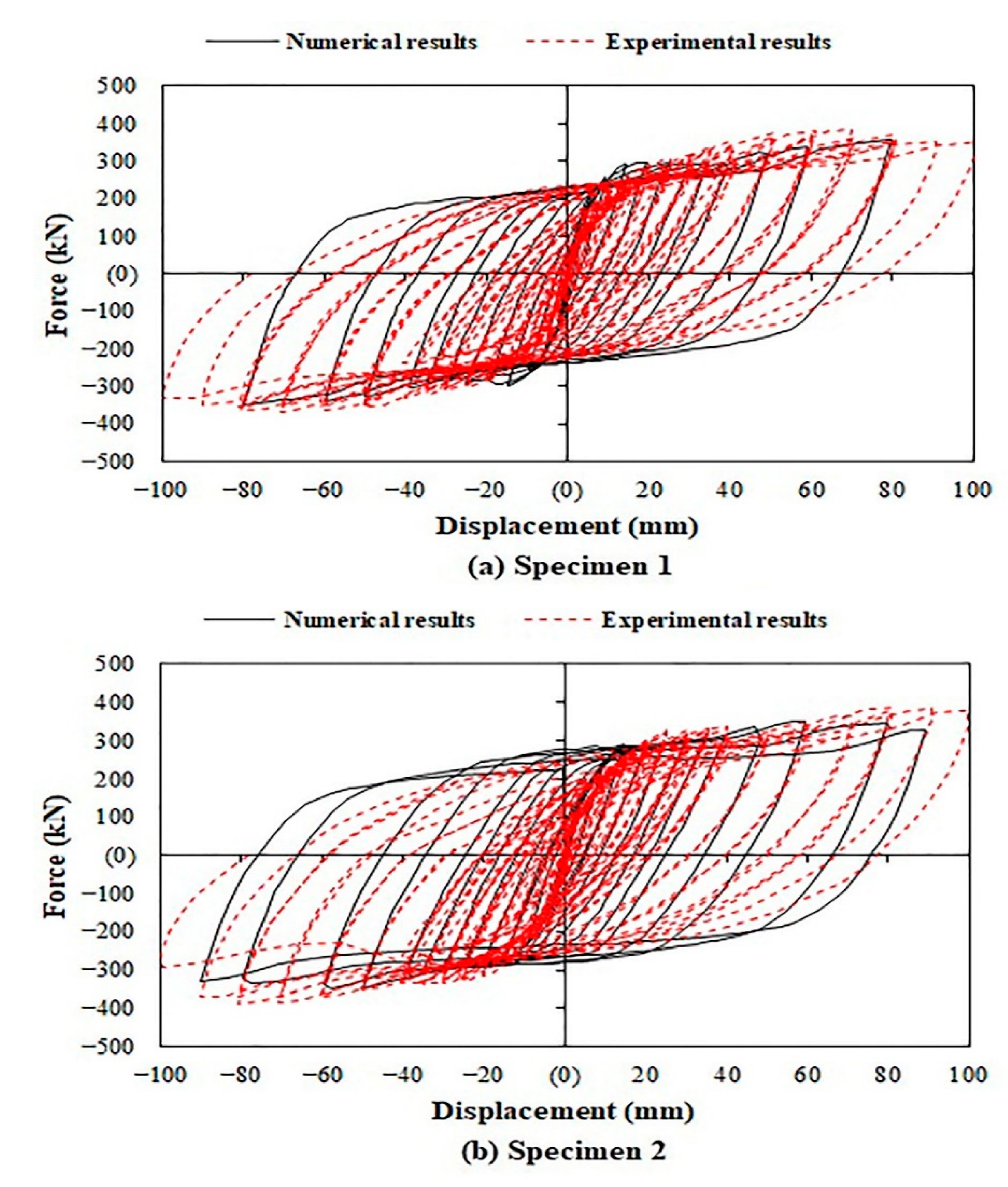
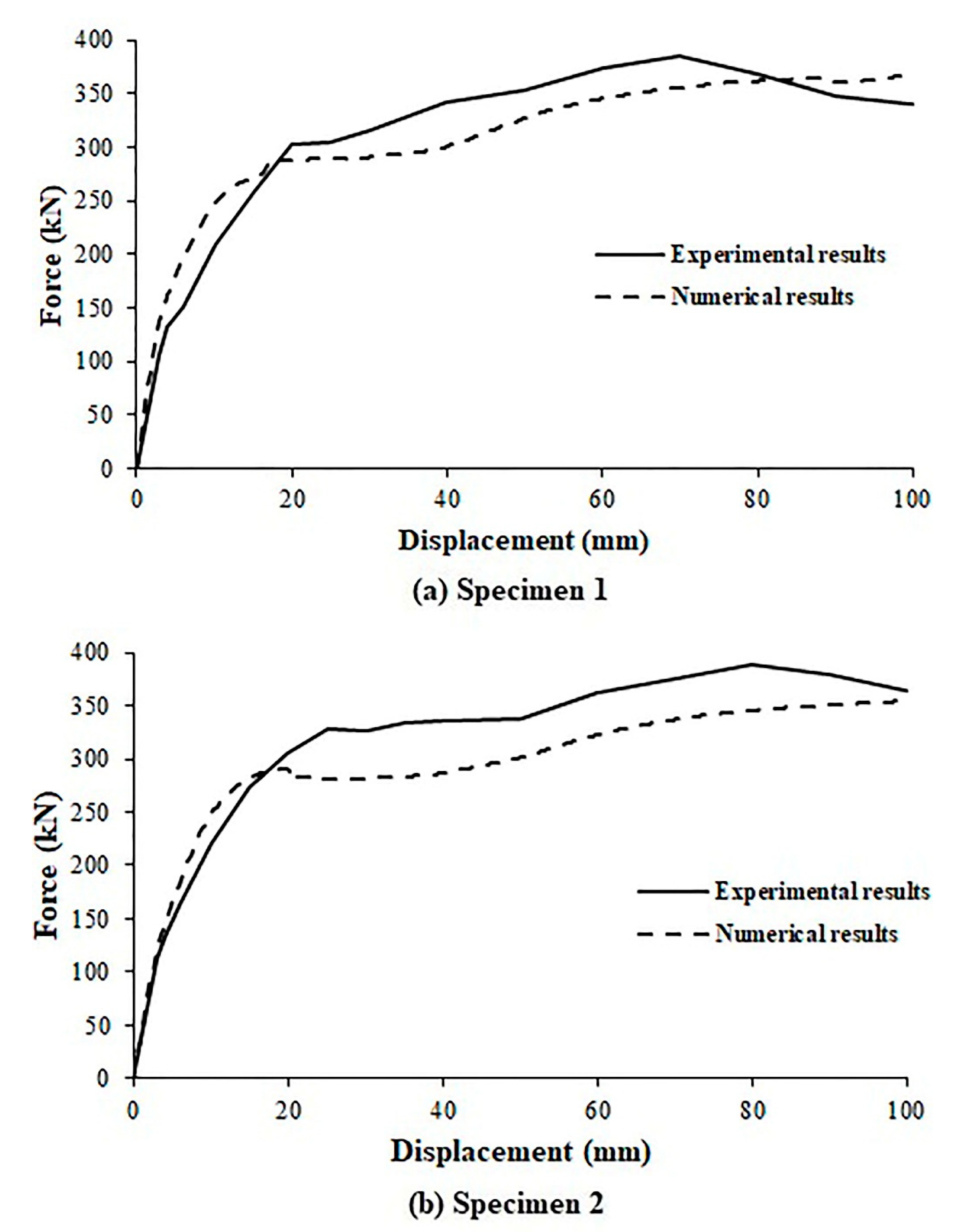
Both material and geometrical nonlinearities were considered in the analysis. The material nonlinearity was taken into account with the assumption of a multi-linear stress-strain curve for steel material using the coupon test results (see Figure 19). The von Mises yield criterion and a combined isotropic-kinematic hardening model based on the work of Lemaitre and Chaboche [36] were applied in the numerical analysis. The analysis of both tested specimens was implemented without an initial imperfection and under the cyclic horizontal displacement-controlled loading. Figure 20 indicates the force-displacement curves of both specimens due to cyclic loading obtained by numerical modeling and the experimental investigation. Figure 21 shows the envelope of the experimental force-displacement curves due to cyclic loading along with the numerical force-displacement curves for both specimens.
As illustrated in Figure 20 and similar to the results reported by Emami et al. [9] for CSIPs without opening, the hysteresis loops are stable, and no pinching is seen in the hysteresis loops. It should be noted that both tested specimens reached almost 6% story drift without collapse. The differences seen in Figure 20 and Figure 21 between the experimental and numerical results could be related to the idealization of the stress-strain curve of material behavior with a multi-linear curve along with the effects of welding and bending of flat steel plates implemented to create corrugated plates.
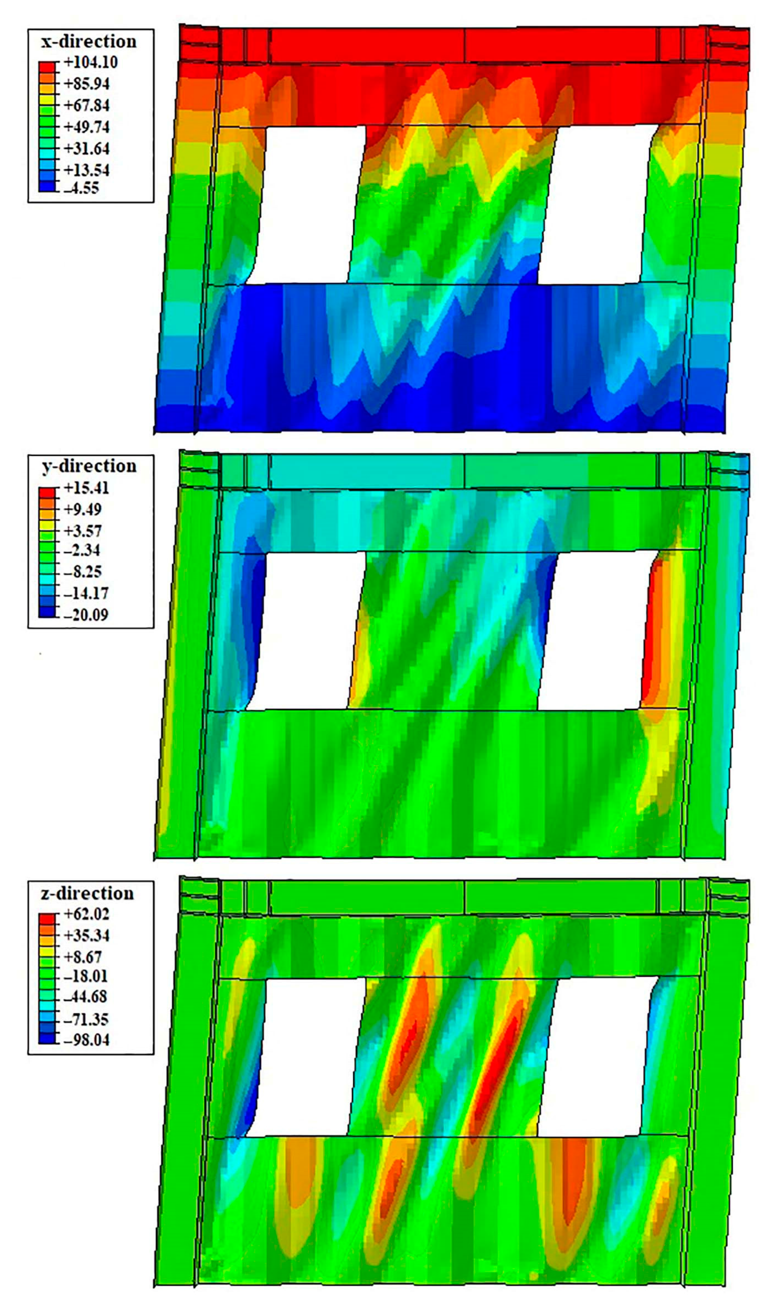
Figure 22 and Figure 23 show the numerical results for the final deformation form of specimens 1 and 2, respectively. As specified in Figure 22 and Figure 23, the maximum deformation of the infill plate in the z-direction (out-of-plane direction) is, respectively, 84 mm and 98 mm for specimens 1 and 2, which is close to the experimental measurement. Deformations of the infill plate in the z-direction appeared in the form of depression and protrusion in the sheet. Figure 22 and Figure 23 also show that the amount of deformation in the y-direction is low.
4.2. Parametric Analysis
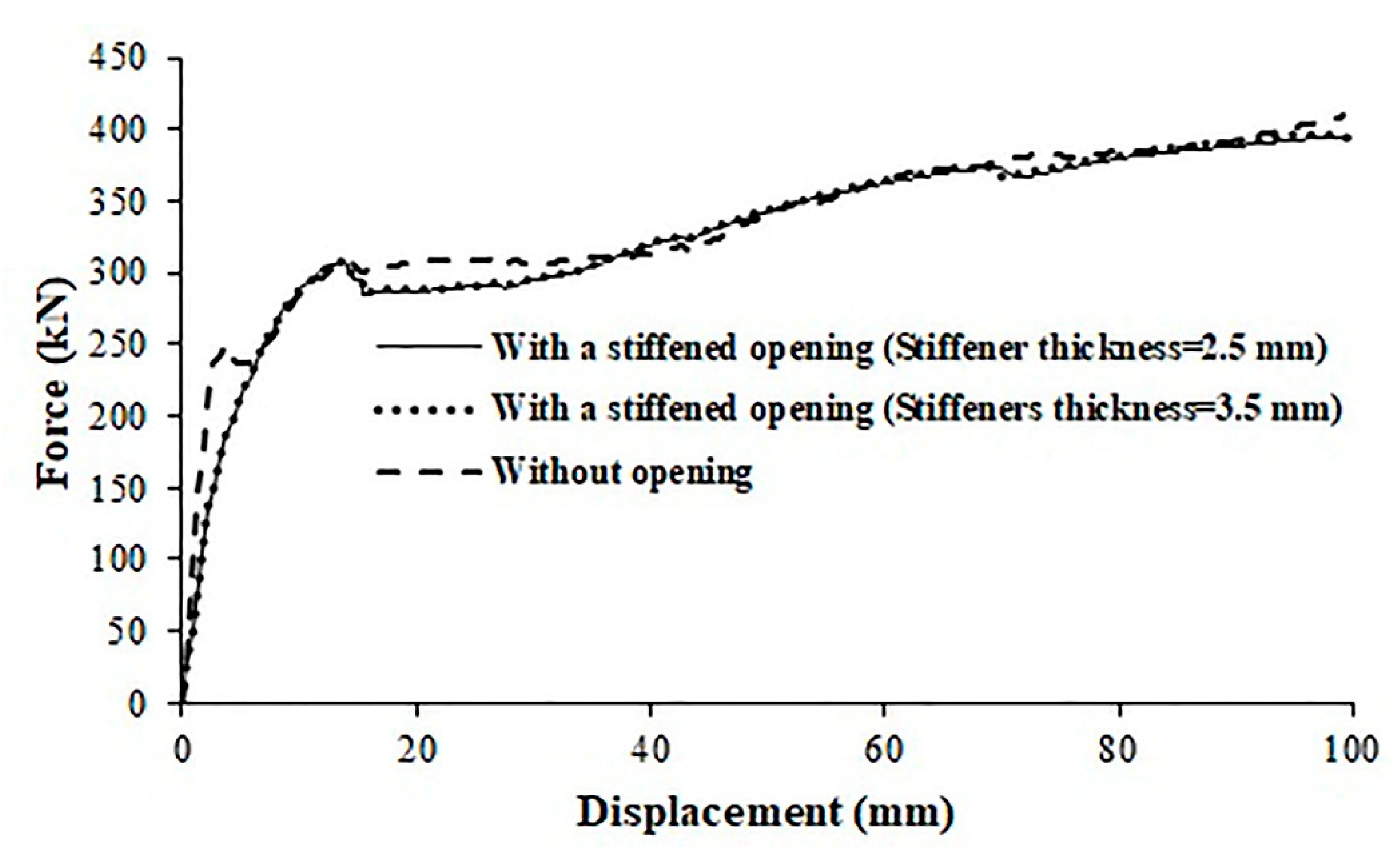
The force-displacement curves of several CSIPs using the numerical results are shown in Figure 24 and Figure 25. Dimensions, material properties and location of opening are basically similar to specimen 1 except for characteristics that are specified. The width of all stiffeners used around the stiffened opening is 70 cm.
Referring to Figure 24, the CSIP with an opening has the same initial stiffness and 20% larger ultimate strength compared to that panel without an opening when the plate thickness for the panel with one opening and the panel without an opening is, respectively, 2 mm and 1.25 mm. Moreover, it is shown in Figure 24 that the initial stiffness and ultimate strength of CSIPs with an opening increase by the increase of the plate thickness. Figure 25 indicates that using stiffeners around the opening in CSIPs has an insignificant effect on the initial stiffness. Moreover, Figure 25 shows that the ultimate strength of CSIPs with a stiffened opening is close to the ultimate strength of the CSIP without an opening. Finally, Figure 25 shows that increasing the thickness of stiffeners does not affect the performance of CSIPs with a stiffened opening.
5. Summary and Conclusions
In this study, two specimens were tested due to cyclic loading to consider the effect of opening on the performance of steel trapezoidal corrugated infill panels. In addition, the effect of the infill plate thickness and the use of stiffeners around the opening on the performance of CSIPs with an opening was considered by performing numerical analyses. The obtained results are presented below:
- The initial stiffness, ultimate strength and ductility ratio of two tested specimens with an opening were 65%, 21% and 39% smaller compared to the specimen without an opening, respectively. The opening percentage of both specimens was equal to 18%.
- The energy dissipation capacity of the specimen without an opening was 21% larger than the specimen with one opening.
- The energy dissipation capacity of the specimen with two openings was 8% larger than the specimen with one opening. The beam yielding along with the columns yielding in the specimen with two openings occurred at larger strains compared to the specimen with one opening. Therefore, the performance of the specimen with two openings is somewhat better than the specimen with one opening, while the opening percentage is the same for both tested specimens.
- Similar to the specimen without opening, both tested specimens with opening dissipated energy by plastic deformations without any pinching in the hysteretic loops.
- The numerical results indicated that the reduction of ultimate strength and initial stiffness of CSIPs due to the existence of an opening can be compensated by the increase of the infill plate thickness.
- The numerical results specified that the ultimate strength of CSIPs with and without a stiffened opening is close to each other.
Author Contributions
Conceptualization, M.Y.G. and M.M.; methodology, M.Y.G. and M.M.; software, M.Y.G.; validation, M.Y.G.; formal analysis, M.Y.G. and M.M.; investigation, M.Y.G. and M.M.; resources, M.Y.G. and M.M.; data curation, M.Y.G.; writing—original draft preparation, M.Y.G.; writing—review and editing, M.M.; visualization, M.Y.G.; supervision, M.M.; funding acquisition, M.Y.G. All authors have read and agreed to the published version of the manuscript.
Funding
This research received no external funding.
Conflicts of Interest
The authors declare no conflict of interest.
References
- Driver, R.G.; Kulak, G.L.; Kennedy, D.J.L.; Elwi, A.E. Cyclic test of four-story steel plate shear wall. J. Struct. Eng. 1998, 124, 112–120. [Google Scholar] [CrossRef]
- Ghosh, S.; Adam, F.; Das, A. Design of steel plate shear walls considering inelastic drift demand. J. Construct. Steel Res. 2009, 65, 1431–1437. [Google Scholar] [CrossRef]
- Kang, T.H.K.; Martin, R.D.; Park, H.G.; Wilkerson, R.; Youssef, N. Tall building with steel plate shear walls subject to load reversal. Struct. Des. Tall Special Build. 2013, 22, 500–520. [Google Scholar] [CrossRef]
- Moradi, M.J.; Hariri-Ardebili, M.A. Developing a library of shear walls database and the neural network based predictive meta-model. Appl. Sci. 2019, 9, 2562. [Google Scholar] [CrossRef] [Green Version]
- Tong, J.Z.; Guo, Y.L. Elastic buckling behavior of steel trapezoidal corrugated shear walls with vertical stiffeners. Thin-Wall Struct. 2015, 95, 31–39. [Google Scholar] [CrossRef]
- Hosseinzadeh, L.; Mofid, M.; Aziminejad, A.; Emami, F. Elastic interactive buckling strength of corrugated steel shear wall under pure shear force. Struct. Des. Tall Special Build. 2017, 26, e1357. [Google Scholar] [CrossRef]
- Gholizadeh, M.; Yadollahi, Y. Comparing steel plate shear wall behavior with simple and corrugated plates. Appl. Mech. Mater. 2012, 147, 80–85. [Google Scholar] [CrossRef]
- Hosseinzadeh, L.; Emmami, F.; Mofid, M. Experimental investigation on the behavior of corrugated steel shear wall subjected to the different angle of trapezoidal plate. Struct. Des. Tall Special Build. 2017, 26, e1390. [Google Scholar] [CrossRef]
- Emmami, F.; Mofid, M.; Vafai, A. Experimental study on cyclic behavior of trapezoidally corrugated steel shear walls. Eng. Struct. 2013, 48, 750–762. [Google Scholar] [CrossRef]
- Vigh, L.G.; Deierlein, G.G.; Miranda, E.; Liel, A.B.; Tipping, S. Seismic performance assessment of steel corrugated shear wall system using non-linear analysis. J. Construct. Steel Res. 2013, 85, 48–59. [Google Scholar] [CrossRef]
- Shimizu, N.; Kanno, R.; Ikarashi, K.; Sato, K.; Hanya, K. Cyclic behavior of corrugated steel shear diaphragms with end failure. J. Struct. Eng. 2013, 139, 796–806. [Google Scholar] [CrossRef]
- Vigh, L.G.; Liel, A.B.; Deierlein, G.G.; Miranda, E.; Tipping, S. Component model calibration for cyclic behavior of a corrugated shear wall. Thin-Wall Struct. 2014, 75, 53–62. [Google Scholar] [CrossRef]
- Emmami, F.; Mofid, M. On the hysteretic behavior of trapezoidally corrugated steel shear walls. Struct. Des. Tall Special Build. 2014, 23, 94–104. [Google Scholar] [CrossRef]
- Farzampour, A.; Mansouri, I.; Hu, J.W. Seismic behavior investigation of the corrugated steel shear walls considering variations of corrugation geometrical characteristics. Int. J. Steel Struct. 2018, 18, 1297–1305. [Google Scholar] [CrossRef]
- Cao, Q.; Huang, J. Experimental study and numerical simulation of corrugated steel plate shear walls subjected to cyclic loads. Thin-Wall Struct. 2018, 127, 306–317. [Google Scholar] [CrossRef]
- Zhang, W.; Mahdavian, M.; Yu, C. Lateral strength and deflection of cold-formed steel shear walls using corrugated sheathing. J. Construct. Steel Res. 2018, 148, 399–408. [Google Scholar] [CrossRef]
- Tipping, S.; Stojadinovic, B. Innovative Corrugated Steel Shear Walls for Multi-Story Residential Buildings. In Proceedings of the 14th World Conference on Earthquake Engineering, Beijing, China, 12–17 October 2008. [Google Scholar]
- Topkaya, C.; Kurban, C.O. Natural periods of steel plate shear wall systems. J. Construct. Steel Res. 2009, 65, 542–551. [Google Scholar] [CrossRef]
- Berman, J.W. Seismic behavior of code designed steel plate shear walls. Eng. Struct. 2011, 33, 230–244. [Google Scholar] [CrossRef]
- Bhowmick, A.K.; Grondin, G.Y.; Driver, R.G. Estimating fundamental periods of steel plate shear walls. Eng. Struct. 2011, 33, 1883–1893. [Google Scholar] [CrossRef]
- Liu, S.; Warn, G.P. Seismic performance and sensitivity of floor isolation systems in steel plate shear wall structures. Eng. Struct. 2012, 42, 115–126. [Google Scholar] [CrossRef]
- Qu, B.; Guo, X.; Chi, H.; Pollino, M. Probabilistic evaluation of effect of column stiffness on seismic performance of steel plate shear walls. Eng. Struct. 2012, 43, 169–179. [Google Scholar] [CrossRef]
- Moradi, M.J.; Roshani, M.M.; Shabani, A.; Kioumarsi, M. Prediction of the load-bearing behavior of SPSW with rectangular opening by RBF network. Appl. Sci. 2020, 10, 1185. [Google Scholar] [CrossRef] [Green Version]
- Ahmad Khan, N.; Srivastava, G. Models for strength and stiffness of steel plate shear walls with openings. Structures 2020, 27, 2096–2113. [Google Scholar] [CrossRef]
- Hossienzadeh, S.A.A.; Tehranizadeh, M. Introduction of stiffened large rectangular openings in steel plate shear walls. J. Construct. Steel Res. 2012, 77, 180–192. [Google Scholar] [CrossRef]
- Alavi, E.; Nateghi, F. Experimental study on diagonally stiffened steel plate shear walls with central perforation. J. Construct. Steel Res. 2013, 89, 9–20. [Google Scholar] [CrossRef]
- Farzampour, A.; Yekrangnia, M. On the Behavior of Corrugated Steel Shear Walls with and without Opening. In Proceedings of the Second European Conference on Earthquake Engineering and Seismology, Istanbul, Turkey, 25–29 August 2014. [Google Scholar]
- Farzampour, A.; Laman, J.A.; Mofid, M. Behavior prediction of corrugated steel plate shear walls with openings. J. Construct. Steel Res. 2015, 114, 258–268. [Google Scholar] [CrossRef]
- Bahrebar, M.; Kabir, M.Z.; Zirakian, T.; Hajsadeghi, M.; Lim, J.B.P. Structural performance assessment of trapezoidally-corrugated and centrally-perforated steel plate shear walls. J. Construct. Steel Res. 2016, 122, 584–594. [Google Scholar] [CrossRef]
- James, J.; Kumar, A.S. Corrugated steel plate shear wall with opening and stiffener at opening. Int. J. Sci. Res. 2016, 5, 1205–1209. [Google Scholar]
- Shariati, M.; Faegh, S.S.; Mehrabi, P.; Bahavarnia, S.; Zandi, Y.; Rezaee Masoom, D.; Toghroli, A.; Trung, N.T.; Salih, M.N.A. Numerical study on the structural performance of corrugated low yield point steel plate shear walls with circular openings. Steel Compos. Struct. 2019, 33, 569–581. [Google Scholar]
- Bahrebar, M.; Lim, J.B.P.; Clifton, G.C.; Zirakian, T.; Shahmohammadi, A.; Hajsadeghi, M. Perforated steel plate shear walls with curved corrugated webs under cyclic loading. Structures 2020, 24, 600–609. [Google Scholar] [CrossRef]
- Standard Test Methods for Tension Testing of Metallic Materials [Metric]; ASTM E8M-04; ASTM International: West Conshohocken, PA, USA, 2008.
- Acceptance Criteria for Cyclic Racking Shear Tests for Metal-Sheathed Shear Walls with Steel Framing; AC 154; ICC Evaluation Service, Inc.: Brea, CA, USA, 2008.
- Uang, C.M. Establishing R (or Rw) and Cd factors for building seismic provisions. J. Struct. Eng. 1991, 117, 19–28. [Google Scholar] [CrossRef]
- Lemaitre, J.; Chaboche, J.L. Mechanics of Solid Materials; Cambridge University Press: Cambridge, UK, 1990. [Google Scholar]
Figure 1.
Details of specimen 1 (mm).

Figure 2.
Details of specimen 2 (mm).

Figure 3.
Details of the specimen tested by Emami et al. Adapted from ref. [9].
Figure 3.
Details of the specimen tested by Emami et al. Adapted from ref. [9].

Figure 4.
Details of connections.

Figure 5.
Details of connection of bottom beam to laboratory rigid steel floor.

Figure 6.
Test setup of specimen 1.

Figure 7.
Test setup of specimen 2.

Figure 8.
Location of strain gauges used during the test of specimen 1.

Figure 9.
Location of strain gauges used during the test of specimen 2.

Figure 10.
Specimen 1 at the end of loading.

Figure 11.
Specimen 2 at the end of loading.

Figure 12.
Specimen tested by Eamami et al. at the end of loading. Adapted from ref. [9].
Figure 12.
Specimen tested by Eamami et al. at the end of loading. Adapted from ref. [9].

Figure 13.
Force-drift angle curves of studied specimens.

Figure 14.
Stiffness performance of studied specimens.

Figure 15.
Inelastic behavior of the panel, beam and column.

Figure 16.
Real and bilinear force-displacement curves.

Figure 17.
Cumulated energy of tested specimens.

Figure 18.
Finite element models of tested specimens.

Figure 19.
Stress-strain behavior of steel material.

Figure 20.
Hysteretic behavior of tested specimens.

Figure 21.
Force-displacement curves of tested specimens.

Figure 22.
Final deformation form of specimen 1 (mm).

Figure 23.
Final deformation form of specimen 2 (mm).

Figure 24.
Force-displacement curves of four corrugated steel infill panels.

Figure 25.
Force-displacement curves of three corrugated steel infill panels.


Table 1.
Mechanical properties.
| Type | Young’s Modulus (GPa) | Yield Stress (MPa) | Ultimate Stress (MPa) | Percent Elongation (%) |
|---|---|---|---|---|
| Plate | 210 | 221 | 339 | 35.6 |
| Beam | 210 | 359 | 482 | 30.8 |
| Column | 210 | 311 | 411 | 34.9 |
Table 2.
Ductility ratio and dissipated energy during cycles with displacements of 70 and 80 mm.
| Specimens | Ductility Ratio (μ) | Dissipated Energy (kN·m) |
|---|---|---|
| Specimen 1 | 9.7 | 101.9 |
| Specimen 2 | 9.6 | 110.1 |
| Specimen tested by Emami et al. [9] | 16 | 122.9 |
Publisher’s Note: MDPI stays neutral with regard to jurisdictional claims in published maps and institutional affiliations. |
© 2021 by the authors. Licensee MDPI, Basel, Switzerland. This article is an open access article distributed under the terms and conditions of the Creative Commons Attribution (CC BY) license (https://creativecommons.org/licenses/by/4.0/).
Share and Cite
MDPI and ACS Style
Gilvaee, M.Y.; Mofid, M. Experimental/Numerical Evaluation of Steel Trapezoidal Corrugated Infill Panels with an Opening. Appl. Sci. 2021, 11, 3275. https://0-doi-org.brum.beds.ac.uk/10.3390/app11073275
AMA Style
Gilvaee MY, Mofid M. Experimental/Numerical Evaluation of Steel Trapezoidal Corrugated Infill Panels with an Opening. Applied Sciences. 2021; 11(7):3275. https://0-doi-org.brum.beds.ac.uk/10.3390/app11073275
Chicago/Turabian StyleGilvaee, Majid Yaseri, and Massood Mofid. 2021. "Experimental/Numerical Evaluation of Steel Trapezoidal Corrugated Infill Panels with an Opening" Applied Sciences 11, no. 7: 3275. https://0-doi-org.brum.beds.ac.uk/10.3390/app11073275
Note that from the first issue of 2016, this journal uses article numbers instead of page numbers. See further details here.