
Finite Element Analysis on Block Shear Mechanism of Lean Duplex Stainless Steel Welded Connections


1
University Core Research Center for Disaster-Free and Safe Ocean City Construction, Dong-A University, Busan 49315, Korea
2
Department of Architectural Engineering, Dong-A University, Busan 49315, Korea
3
Department of Architectural Engineering, Hanbat National University, Daejeon 34158, Korea
*
Author to whom correspondence should be addressed.
Appl. Sci. 2021, 11(7), 3283; https://0-doi-org.brum.beds.ac.uk/10.3390/app11073283
Submission received: 17 March 2021
/
Revised: 30 March 2021
/
Accepted: 1 April 2021
/
Published: 6 April 2021
(This article belongs to the Section Civil Engineering)
Abstract
:The block shear equations specified in the current AISC specification for structural steel buildings and North American cold-formed steel design specifications are based on research results of carbon steel bolted connections. These equations were found to be inapplicable for the welded connections in the literature. This issue is primarily associated with the use of the incorrect assumption on block shear failure mechanism. The present paper examines the accuracy of various block shear equations available in the design specifications and in the literature. The paper also examines the shear hardening capacity and the level of tensile stress over the critical net area with the results of finite element analysis, in which the fracture simulation is considered. It shows that the block shear capacities of lean duplex stainless steel welded connections can be predicted accurately using tensile stress equal to 1.25Fu, as proposed in the literature.
1. Introduction
The application of stainless steels to structural members has been receiving increasing attention from researchers and engineers owing to their attractive material characteristics compared with conventional carbon steel [1,2,3]. They possess not only high ductility, which enhances the fire performance of a steel structure, but also excellent corrosion resistance, used advantageously in marine structures. However, the irreconcilable conflict between initial material cost and performance has impeded more widespread utilization of stainless steel in the structures.
Nowadays, a novel lean duplex stainless steel, which contains a lower amount of nickel than the austenitic counterpart, has been developed to take economic advantages. In addition, European design code [4] has provided design rules for the lean duplex stainless steel from the 2015 edition, although the current American cold-formed stainless steel standard [5] and Australasian cold-formed steel standard [6] have still not covered it.
Block shear capacity of the steel connections has been assumed as the combination of tensile resistance and shear resistance in the current design codes. In the design for block shear of welded connection, consideration should be given to both the constraint (stress triaxiality) effect and the extent of shear strain hardening. The former is a result of the presence of weldment that hinders necking of the plate material in the direction perpendicular to the loading, while the latter is associated with material ductility.
In fact, the material ductility effects on shear strain hardening capacity have been studied well with experimental and numerical data of bolted connections over a wide range of steel materials by Teh & Uz [7], Mai et al. [8], Jiang et al. [9], Cho et al. [10], and Kim et al. [11].
However, the constraint effect has not yet been demonstrated. Topkaya [12], Oosterhof & Driver [13], and Yuk et al. [14] have pointed out that the block shear mechanism in welded connection under the lateral constriction promoted by the weldment is significantly different from the bolted case. The current design specifications have still not provided separate block shear equations for welded connection.
The present paper thus investigates two issues related to the block shear capacity of welded connection: (i) the constraint effect on the tensile stress and (ii) the shear strain hardening capacity of welded connection in lean duplex stainless steel sheet. A total of 17 test results of welded connection specimens failing in block shear were presented. In order to examine the block shear response, a finite element model coupled with material softening was developed in the present paper. In this way, initiation and propagation of fracture can be simulated. In addition, the stress and strain response over the whole loading history up to the completed fracture can be captured.
2. Available Design Equations for Block Shear Capacity of Fillet Welded Connection
2.1. AISI S100-2016
Section J6.3 of the North American cold formed steel structures code [15] specifies the block shear capacity of the connections in the steel members to be as follows:
where is the material yield stress, is the material tensile strength, is the net tensile area, is the net shear area, and is the gross shear area.
A well-established shear coefficient of 0.6, which is supported by Fox and Schuster [16] through experimental tests, is used for determining the shear resistance component. The block shear provision of the AISI 2016 [15] is the same as the AISC specification for structural steel buildings [17], but subtly different from the Australasian cold-formed steel structures standard [6] that reflects the shear lag effect on the net section efficiency.
The net area and gross area are always coincident with each other. Consequently, the nominal block shear strength is dominated by Equation (1), which assumes shear yielding without strain hardening and, thereby, the current design codes yield underestimated predictions for the block shear capacity of the welded connections by 10~34% [12,18].
2.2. Topkaya
Two coefficients in Equation (2) have been modified by Topkaya [12] for block shear capacity of carbon hot-roll welded connections as follows:
where a tensile coefficient of 1.25 is used to account for high triaxial stress state promoted by the later constriction under the weldment segment, while the von Mises shear yield coefficient of in the European code is used instead of 0.6. It is worth noting that was derived by Schafer et al. [19] based on the maximum principal stress theory. In contrast to the aforementioned design codes, the Topkaya’s block shear equation always assumes the stress on the shear section to be equal to the shear ultimate stress.
3. Experimental Investigation
3.1. Test Materials
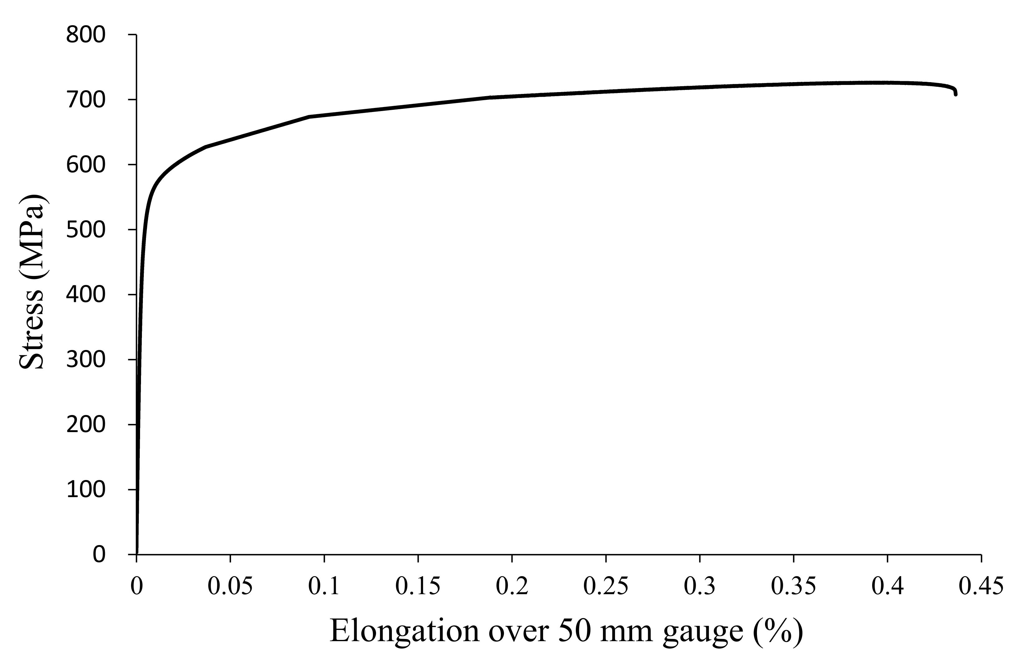
The tested steel material was cold-formed lean duplex stainless sheet steel STS329FLD with a nominal thickness of 3.0 mm, manufactured and supplied by POSCO of Korea. Three tension coupons were cut in the rolling direction. The overall dimensions of the tension coupons were prepared in accordance with section 6 of ASTM E8 [20]. The nominal gauge length and width were 50 mm and 25 mm, respectively. All tension coupons were tested in the hydraulic controlled testing machine with a loading capacity of 300 kN at a constant stroke rate of 0.5 mm/min. A pre-calibrated extensometer of 50 mm gauge length was used to measure the longitudinal strain. Table 1 lists the average base thickness t, elastic modulus E, yield (0.2% proof) stress , tensile strength , and elongation at fracture over the 50 mm gauge. It is obvious that the lean duplex stainless steel used for the present experimental program had strength and ductility, far exceeding the minimum tensile strength and elongation ( MPa, ) specified in the Korean Standard [21]. It can be seen from Figure 1 that the steel experienced gradual yielding, which is characterized by the cold-forming process.
3.2. Specimen Design and Test Setup
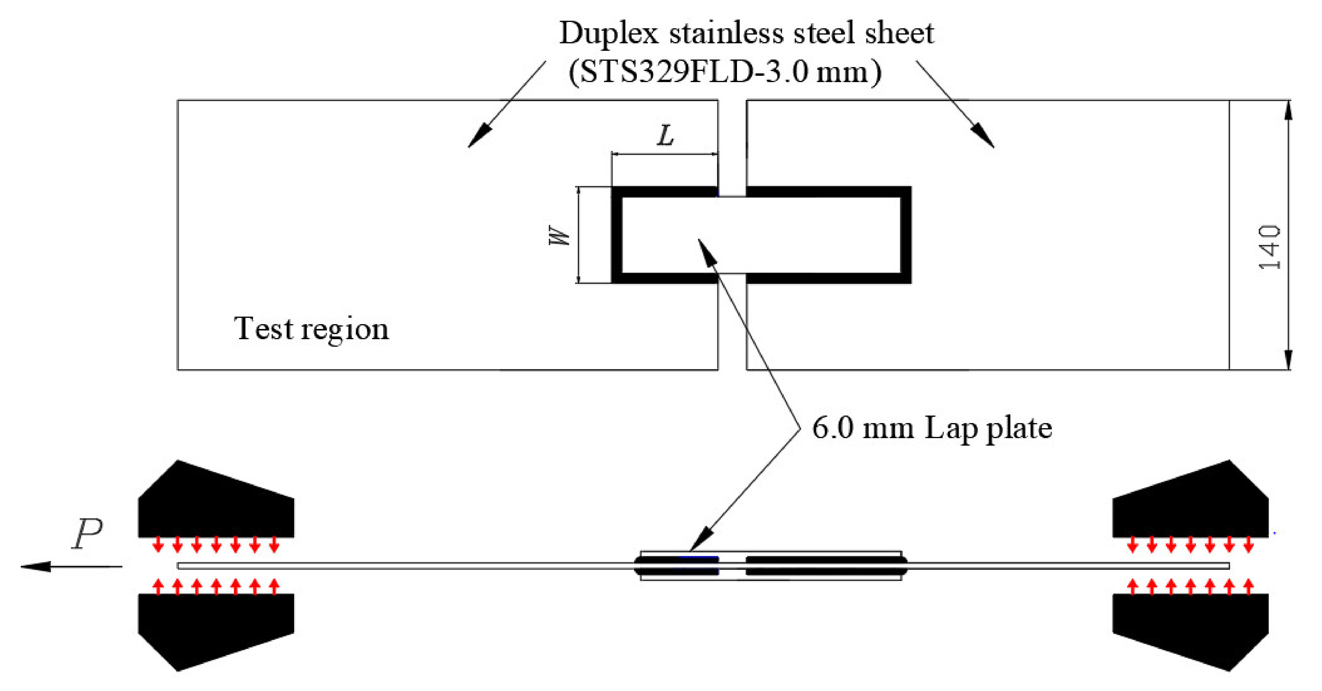
Based on the previous experimental results of austenitic stainless steel fillet welded connections failing in block shear, the geometric configuration and test setup illustrated in Figure 2 were designed. The fillet welded connection specimens consisted of two 6.0 mm thick lap steel plates welded on both sides of 3.0 mm thick steel sheets. All fillet welds were manually fabricated by only one skillful welder to ensure the welding quality and to minimize the variation of weld profiles. A gas tungsten arc welding (GTAW) process was used in the present work with an inverter DC pulse welding machine (TIG 500). The weld size of the fillet weld was designed to be 5 mm. The weld length on the test side was shorter than the other side, so that the fillet welded connection would always fail in the test region.
To investigate the block shear response of various welded configurations, block length (L) was varied with a constant value of block width (W), which results in the block shear aspect ratios (L/W) ranging from 0.69 to 1.47. Before testing, block length and block width that include the weld size were carefully measured at three different locations. The test specimens were labelled to easily identify nominal dimensions. For example, the prefix “L” in the label denotes block length, while the letter “W” denotes block width. For repeated tests, the suffix “a” or “b” is presented in the label. All welded connection specimens were tested in the same manner as the tension coupons described in the preceding section. Two linear variable different transformers (LVDTs) were used to measure the displacements of the connection specimen.
3.3. Experimental Results
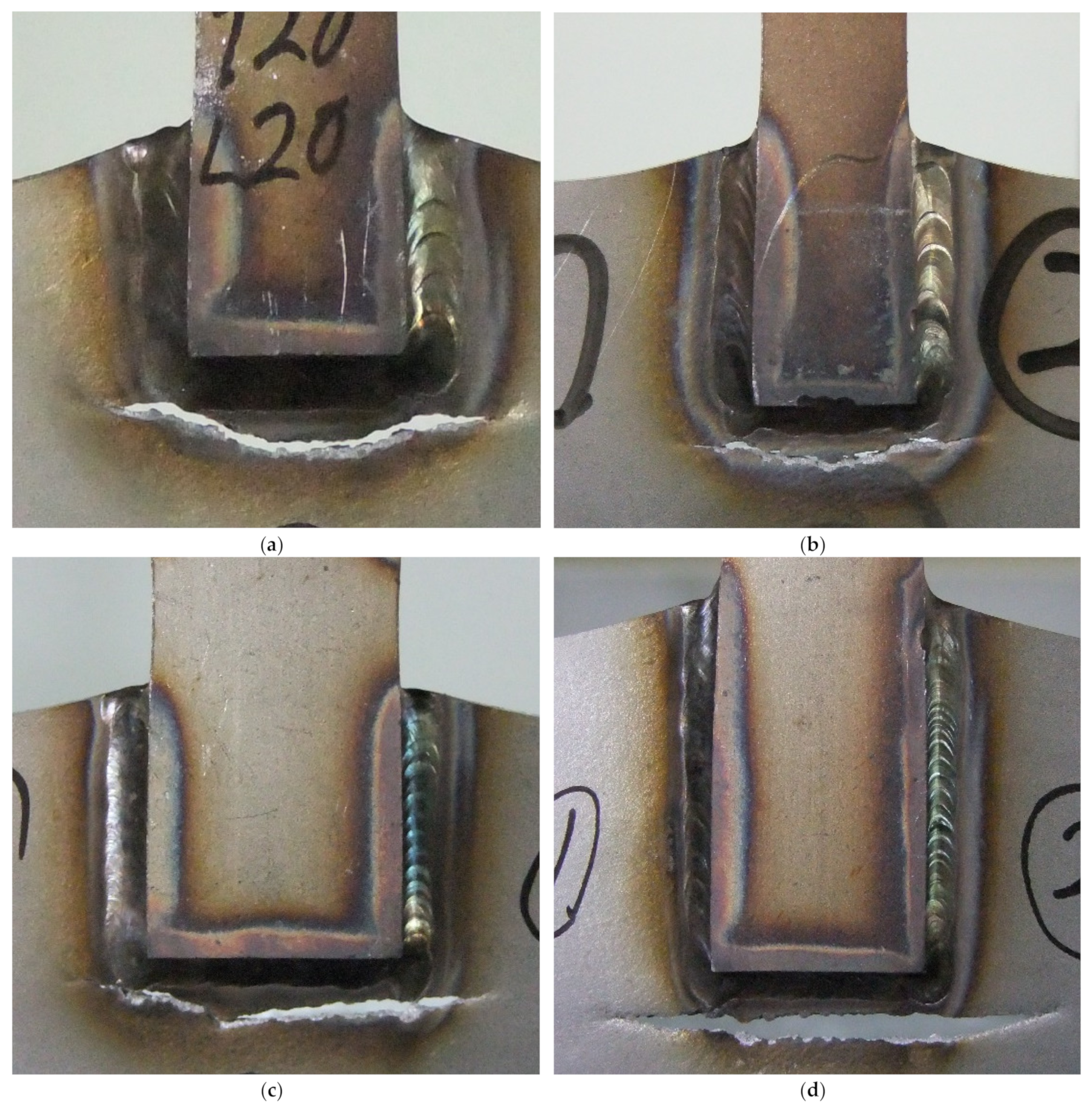
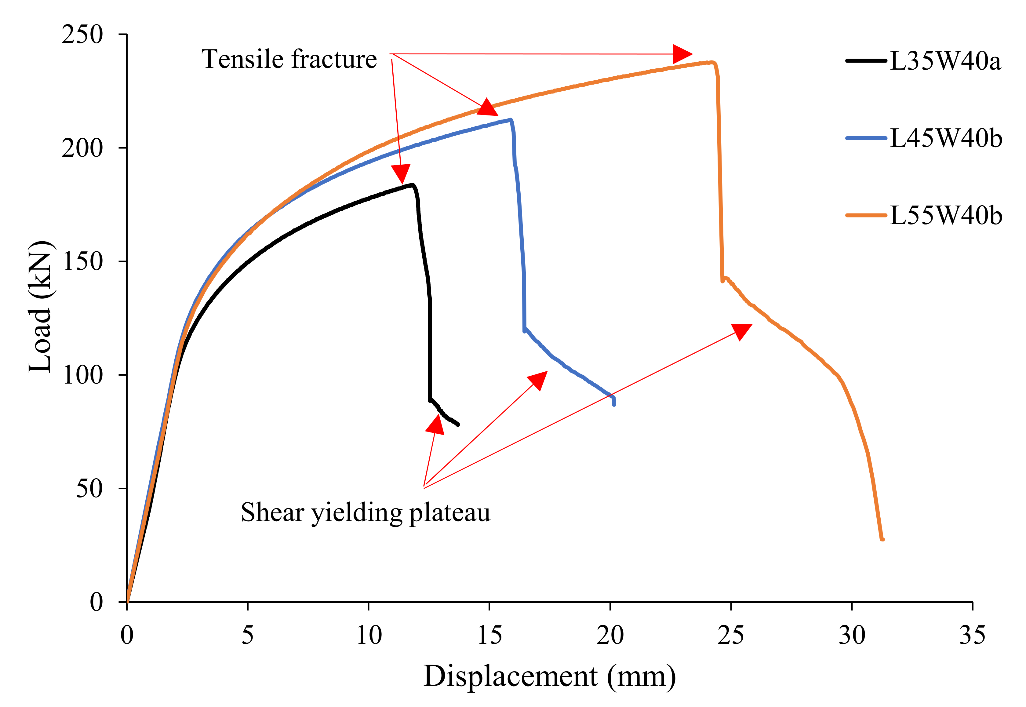
The measured geometric dimensions and the test results of the tested welded connection specimens failing in block shear are listed in Table 2. As demonstrated in the literature, the fillet welded connection has a constraint effect, which inhibits necking of the net tension plane at the weld toe. As a result, tensile fracture is always initiated far away from the toe of the fillet weld at the corner of the lap plate (end return weld), shown in Figure 3. The dominant block shear mechanism was the tensile rupture and shear yielding mechanism, which is evident from the load-deflection graphs shown in Figure 4. Shear yielding was observed after complete tensile fracture.
Table 2 shows the ratios of ultimate test load to predicted strength (called the professional factors) of Equations (1)–(3) for the welded connection specimens. The averaged material properties in Table 1 and the measured values of the geometric dimensions are used for determining the nominal block shear capacity.
It can be seen that the current design specification is conservative for all test specimens. Although the full shear strain hardening assumption, which was found to be accurate for the carbon steel bolted connections in the literature [10], is used, the ultimate block shear strength is underestimated by up to 13% (1/1.15 = 0.87).
The possible explanation for such inaccurate results of the AISI equations is the neglect of the constraint effect that increases stress on the tension section. It is evident from the professional factor of Equation (3) that the ultimate block shear capacity of the tested welded connection can be predicted well when using tensile stress higher than ultimate tensile strength , although it shows a rather low level of accuracy for Specimen L55W50, having the largest block length and block width among the test specimens.
4. Numerical Investigation
4.1. Geometry, Meshing, and Boundary Conditions
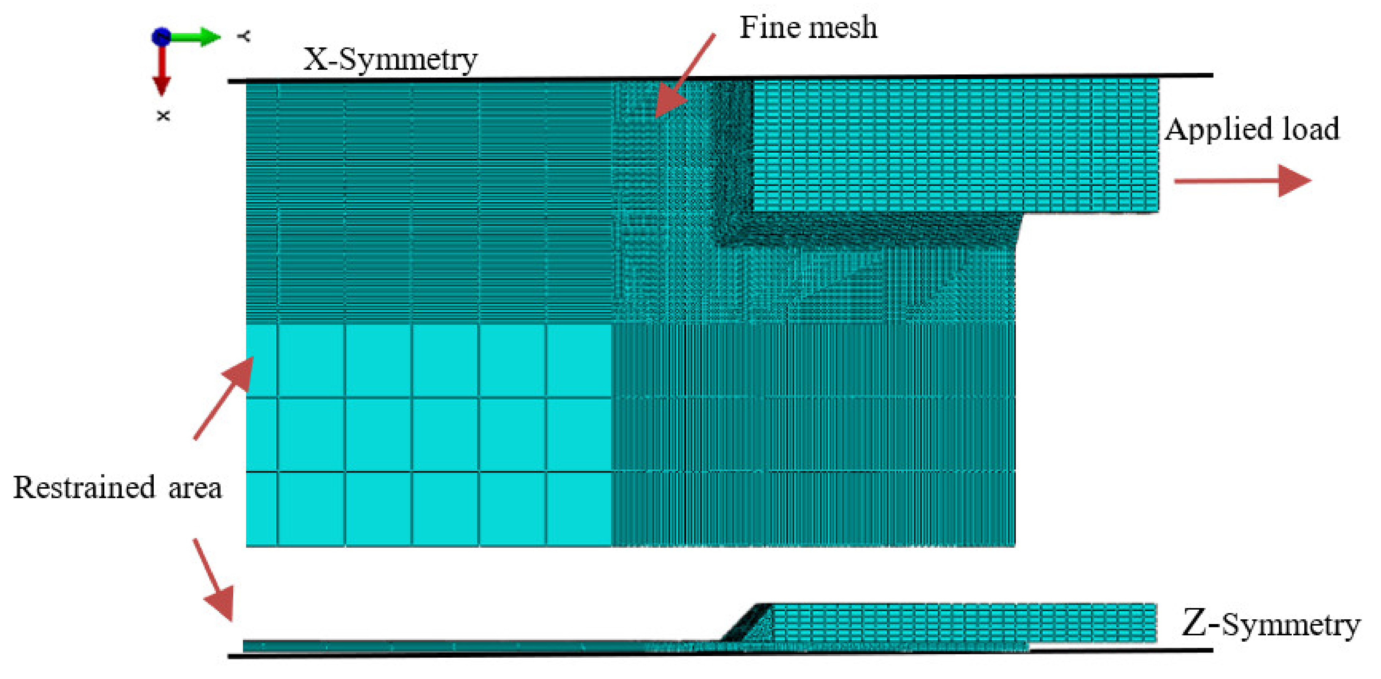
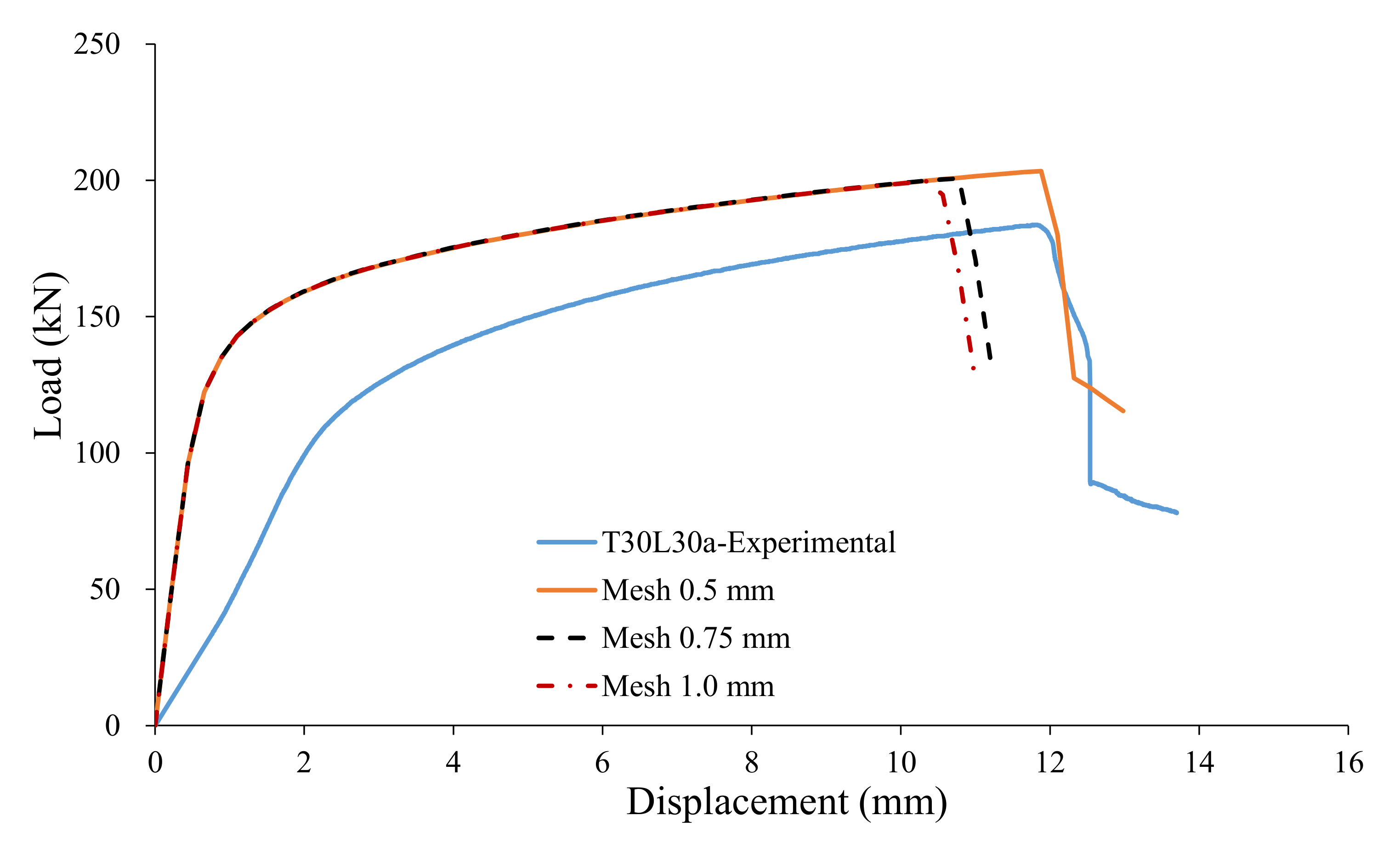
The finite element (FE) software ABAQUS 2018 [22] was employed in the present numerical investigation. The tension coupons and steel plates were modelled as C3D8R solid elements with eight nodes and reduced integration, while weld metal was modelled as the quadratic tetrahedral element C3D10 for ease of meshing in the rounded shape. The more refined mesh is generated in the vicinity of the weld segment where the fracture would take place. Such mesh generation is able to capture stress and strain responses accurately. In order to reduce computational cost, the advantage of the symmetry of the welded connections was taken, as shown in Figure 5. The preliminary FE analysis was also conducted in the present paper to investigate the mesh sensitivity, which is a critical issue in the fracture modeling. Three levels of mesh of 0.50 mm, 0.75, and 1.0 mm were considered. Figure 6 shows that a high level of accuracy can be achieved when the mesh size is 0.50 mm. This result is consistent with the finding of Yan et al. [23] that a mesh size smaller than 0.5 mm should be used in FE analysis (FEA) involving fracture simulation to avoid mesh sensitivity.
4.2. Contact Interactions
The surfaces of fillet welds and the steel components in the connection were tied through the surface-based tie constraint. The finite sliding contact formulation was used to define surface-to-surface contact between the lap plate and the main plate. The tangential behavior was defined through the penalty method, and a friction coefficient of 0.1 was assumed.
4.3. Material and Fracture Modelling
As the tension coupon specimen is in a uniaxial stress state prior to necking, the true stress–strain response can be easily defined using the following conventional equations:
where is the true stress, is the true strain, is the engineering stress, and is the engineering strain.
However, after necking, such equations are no longer valid owing to strain localization and triaxial stress states. The Swift law was used to extrapolate the post-necking true stress–strain relationship, which can be expressed as follows:
where A and B are the material parameters and is the plastic strain.
For the lean duplex stainless steel used in the present work, , , and , which resulted from curve fitting of the measured stress–strain data prior to necking.
In some cases, FE modeling with the conventional plasticity model has been found to overestimate the ultimate load of the steel connections as it does not reflect material softening [24,25]. In the present work, finite element analysis incorporating fracture simulation was performed to achieve more accurate results. Table 3 lists the damage parameters calibrated from the results of standard tension coupons using procedures proposed by Elliott and Teh [26]. The Rice and Tracey [27] model built in ABAQUS [22] was used to set the damage initiation criterion, in which fracture strain at damage onset is set as a function of the stress triaxiality η. The damage evolution law was defined as a nonlinear function of the effective displacement.
4.4. Validation of the FE Modeling
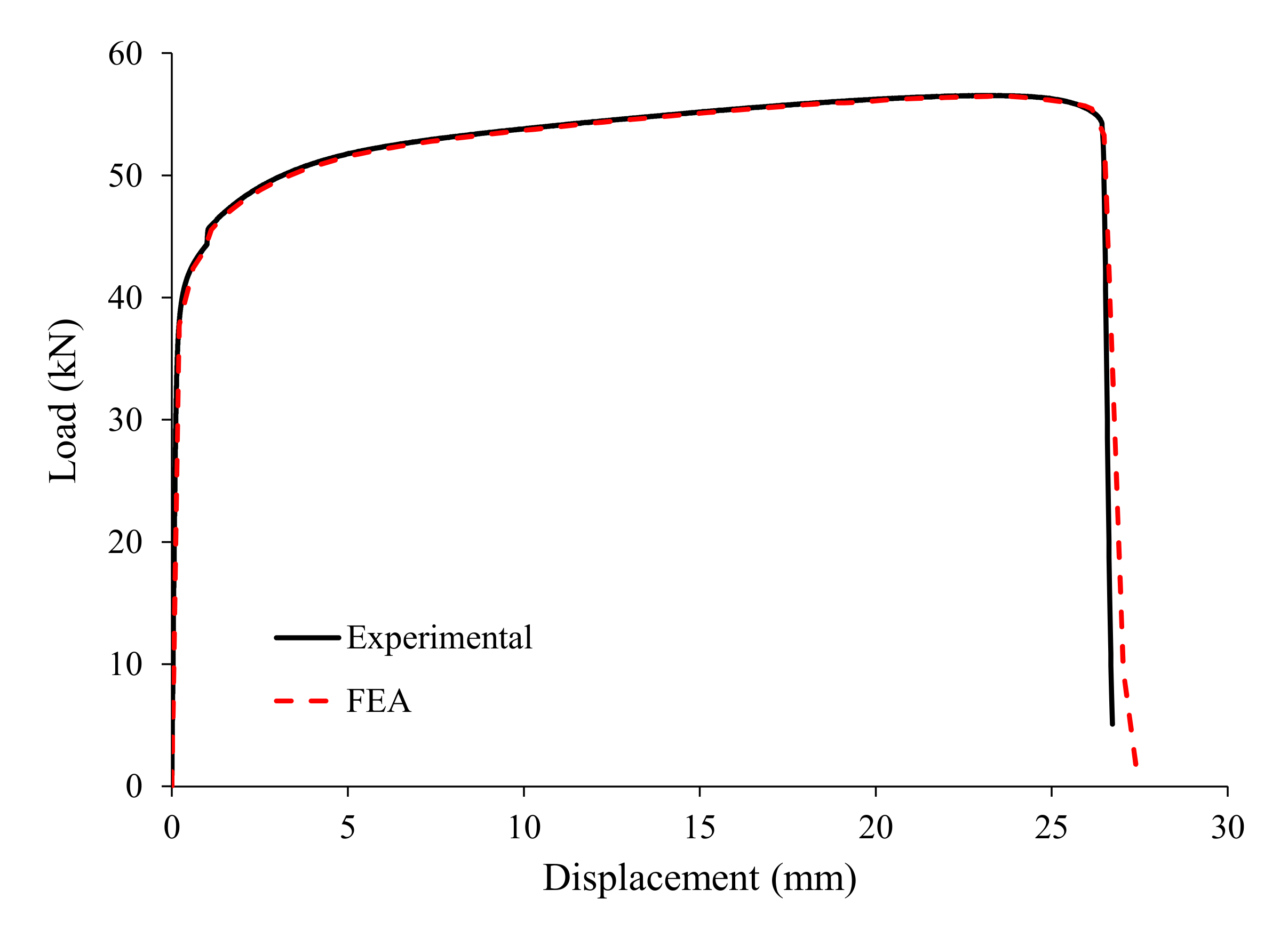
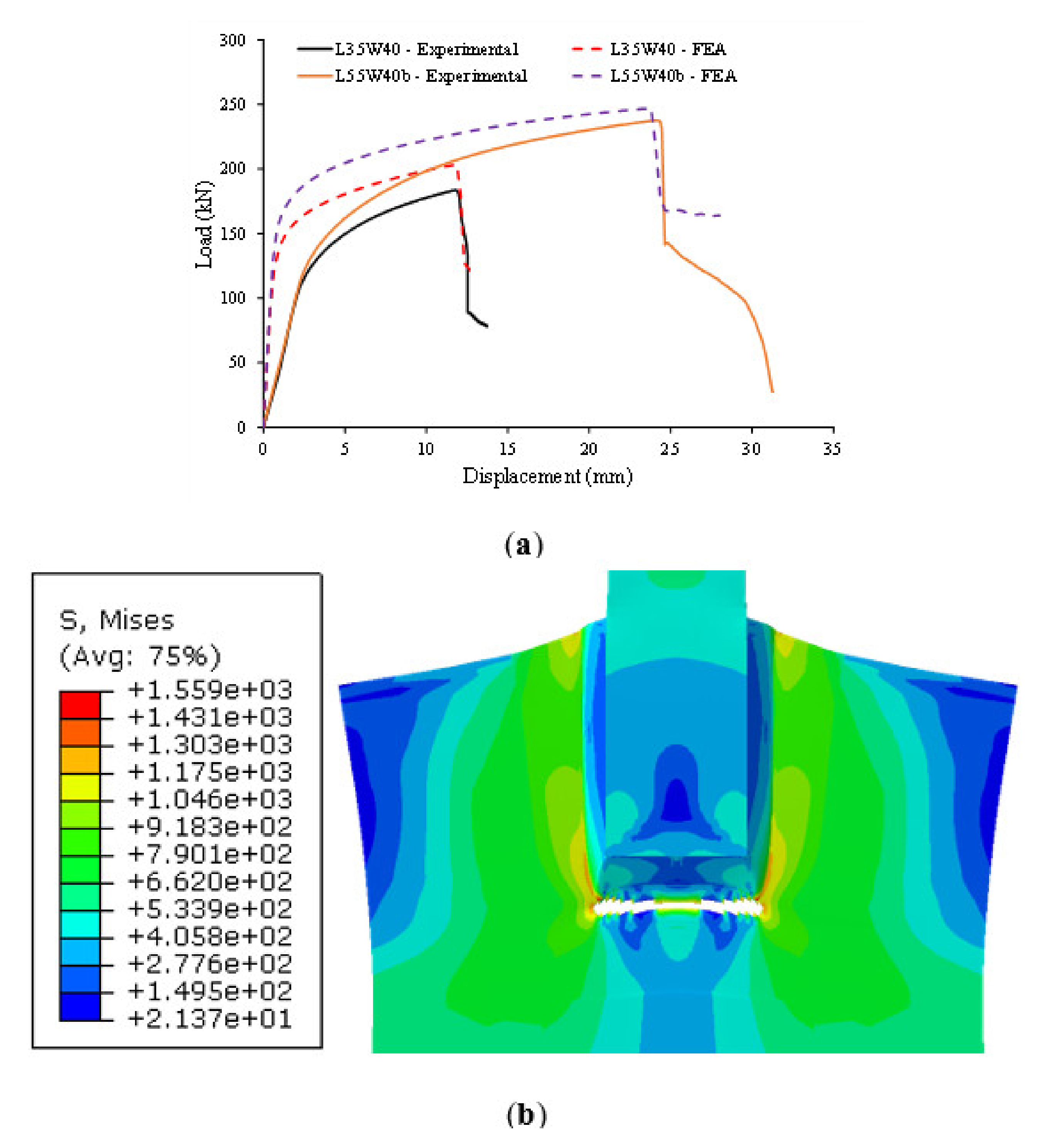
The load-deflection response of FE modeling for tension coupon was validated against the results obtained in the physical test, as shown in Figure 7. It shows that the FE model coupled with fracture was able to predict the behavior of the tension coupons. The developed fracture model is in the desired agreements with the test results of the welded connection specimens, including fracture mode (Figure 3d vs. Figure 8b) and the load-deflection responses (Figure 7 and Figure 8a).
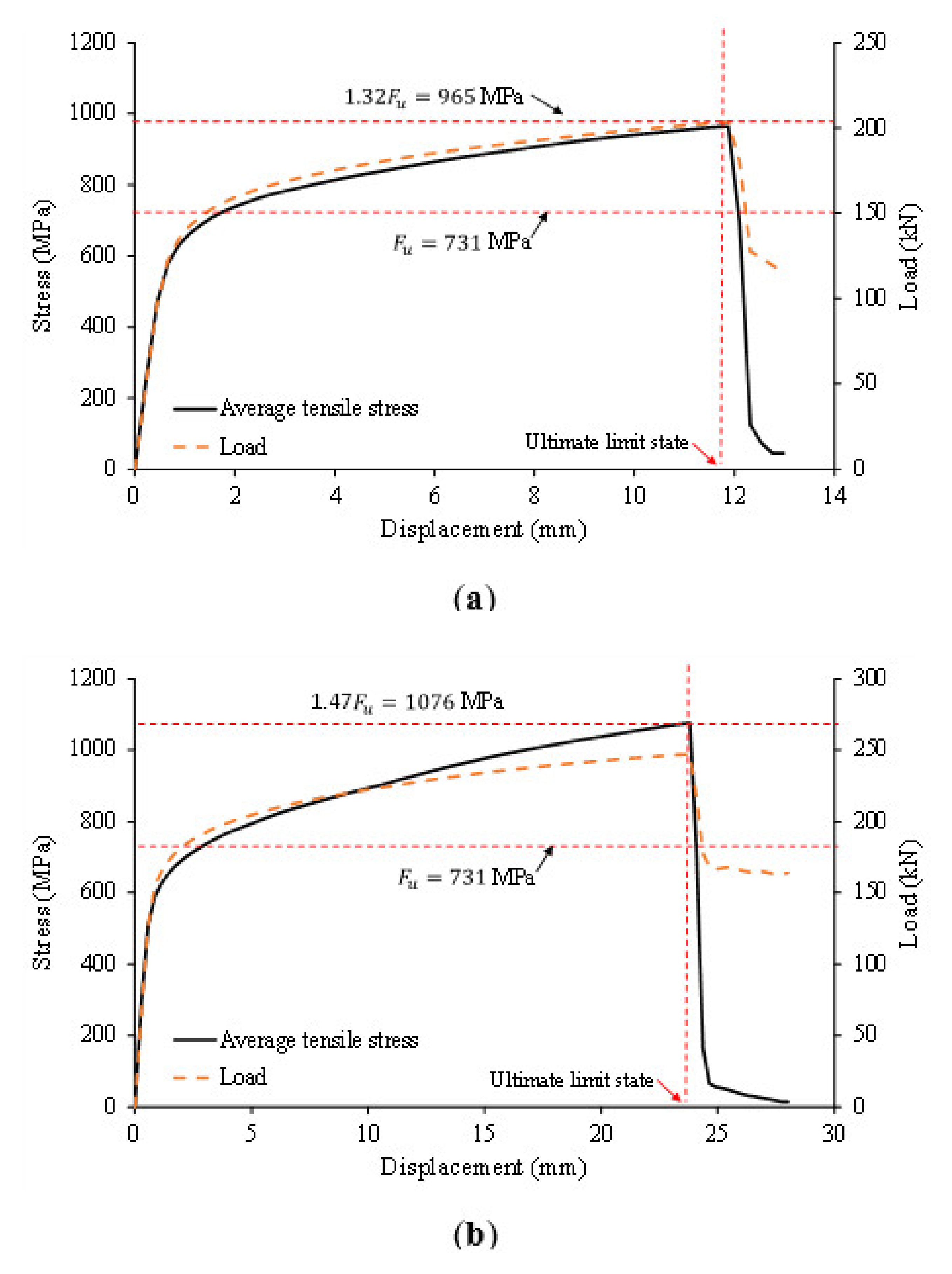
4.5. Constraint (Stresss Triaxiality) Effect
Figure 9 shows that, at the ultimate limit state, the average tensile stress over the tension section of the lean duplex stainless steel welded connection was greater than the tensile strength of steel material under the lateral constraint promoted by the weld segment. It also shows that the constraint effect on the average tensile stress is significantly more pronounced with a larger weld length. The average tensile stress in Model L35W40 at the ultimate load of 203.4 kN was 965 MPa, whereas that in Model L35W55 at the ultimate load of 247.1 kN was 1076 MPa. It is apparent from Figure 10 that the tensile stresses are more uniformly distributed on the critical net section in the latter model than in the former one.
The results of the present finite element analysis are sufficient to justify Topkaya’s contention that the constraint effect should be considered in the design check of the fillet welded connection failing in block shear.
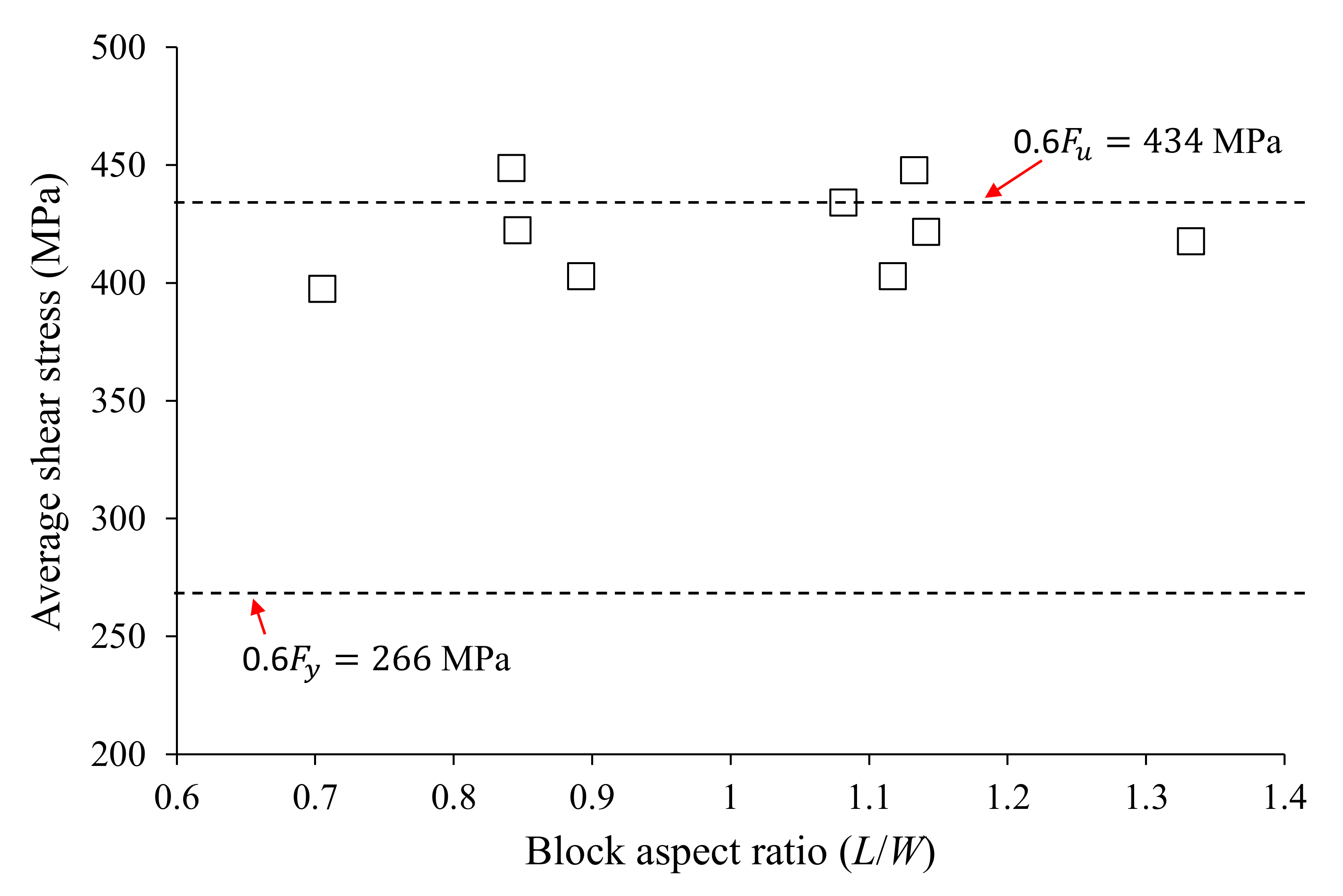
4.6. Shear Strain Hardening
Cho et al. [10] demonstrated the extent of strain hardening on the shear section is quite dependent on the level of material ductility. The use of the shear ultimate stress was inaccurate for the ultra-high strength steel (S1150) bolted connections having very limited ductility as reflected in the elongation at fracture. but its use is accurate for the mild steel (S275) specimens, which had comparable ductility and a lower tensile strength to yield stress ratio to the lean-duplex stainless steel. The similar outcome can be observed in the results of the present finite element analysis. The average shear stress close to the shear ultimate stress of was achieved, as shown in Figure 11.
5. Summary and Conclusions
An experimental program including 17 specimens was performed to investigate their block shear capacity and behavior of lean duplex stainless steel (STS329FLD) welded connections. It was found that the American design code (AISI) significantly underestimated the block shear capacities of the lean duplex stainless steel welded connections, whereas the equation proposed by Topkaya [12], which accounts for the constraint (stress triaxiality) effect, was found to be accurate.
For further interpretation on the block shear mechanism of welded connections, a finite element model coupled with damage was developed. The model can provide stress and strain distributions that could not be seen in the physical tests. It was found that, at the ultimate block shear limit state, the average tensile stress involving tension resistance component is higher than the tensile strength of steel material, while the average shear stress is closed to the full strain hardening assumption of . It was also found that the constriction effect become more predominant in the specimens with a larger weld length. To clearly understand the constriction effect according to the geometric dimensions of weld length, further investigation is needed in a future paper.
Author Contributions
Conceptualization, Y.C. and T.K.; methodology, T.K.; software, Y.C., D.-K.K., and J.K.; validation, T.K.; formal analysis, Y.C. and J.K.; investigation, T.K. and D.-K.K.; resources, T.K. and Y.C.; data curation, T.K. and J.K.; writing—original draft preparation, Y.C.; writing—review and editing, T.K.; visualization, D.-K.K. and J.K.; supervision, T.K.; project administration, T.K.; funding acquisition, Y.C. and T.K. All authors have read and agreed to the published version of the manuscript.
Funding
The first author is supported by the Basic Science Research Program through the National Research Foundation of Korea (NRF) funded by the Ministry of Education (No. NRF-2018R1D1A1B07046021). The last author is supported by Korea Institute of Energy Technology Evaluation and Planning (KETEP) and the Ministry of Trade, Industry, & Energy (MOTIE) of the Republic of Korea (No. 20204030200080). The authors would like to thank POSCO of Korea for providing the test materials (STS329FLD) used in this study.
Institutional Review Board Statement
Not applicable.
Informed Consent Statement
Not applicable.
Data Availability Statement
Data is contained within the article.
Conflicts of Interest
The authors declare no conflict of interest.
References
- Lee, H.C.; Hwang, B.K.; Kim, T.S. Ultimate strength of austenitic stainless fillet-welded connections with weld metal fracture. Thin Walled Struct. 2017, 116, 145–153. [Google Scholar] [CrossRef]
- Wang, F.; Young, B.; Gardner, L. Compressive behaviour and design CFDST cross-sections with stainless steel outer tubes. J. Constr. Steel Res. 2020, 170, 105942. [Google Scholar] [CrossRef]
- Cai, Y.; Zhou, F.; Wang, L.; Young, B. Design of lean duplex stainless steel tubular sections subjected to concentrated end bearing loads at elevated temperatures. Thin Walled Struct. 2021, 160, 107298. [Google Scholar] [CrossRef]
- European Committee for Standardization (ECS). Eurocode 3: Design of Steel Structures—Part 1.4: General Rules–Supplementary Rules for Stainless Steel; EN 1993-1-4-:2015; European Committee for Standardization: Brussels, Belgium, 2015. [Google Scholar]
- American Society of Civil Engineers (ASCE). Specification for the Design of Cold-Formed Stainless Steel Structural Members; American Society of Civil Engineers: Reston, VA, USA, 2002. [Google Scholar]
- Standards Australia/Standards New Zealand (SA/SNZ). Cold-Formed Steel Structures; AS/NZS 4600:2018; Standards Australia/Standards New Zealand: Sydney, NSW, Australia, 2018. [Google Scholar]
- Teh, L.H.; Uz, M.E. Block shear failure planes of bolted connections—Direct experimental verifications. J. Constr. Steel Res. 2015, 111, 70–74. [Google Scholar] [CrossRef] [Green Version]
- Mai, B.V.; Pham, C.H.; Hancock, G.J.; Nguyen, G.D. Block shear strength and behaviour of cold-reduced G450 steel bolted connections using DIC. J. Constr. Steel Res. 2019, 157, 151–160. [Google Scholar] [CrossRef]
- Jiang, B.; Yam, M.C.H.; Ke, K.; Lam, A.C.C.; Zhao, Q. Block shear failure of S275 and S690 steel angles with single-line bolted connections. J. Constr. Steel Res. 2020, 106068. [Google Scholar] [CrossRef]
- Cho, Y.H.; Teh, L.H.; Ahmed, A.; Young, B. Material ductility and temperature effects on block shear capacity of bolted connections. J. Constr. Steel Res. 2021, 106461. [Google Scholar] [CrossRef]
- Kim, T.S.; Hong, S.K.; Hwang, B.K.; Kim, J.S. Block shear capacity in cold-formed lean duplex steel double-shear bolted connections. Thin Walled Struct. 2021, 161, 107520. [Google Scholar] [CrossRef]
- Topkaya, C. Block shear failure of gusset plates with welded connections. Eng. Struct. 2007, 29, 11–20. [Google Scholar] [CrossRef]
- Oosterhof, S.A.; Driver, R.G. Effects of connection geometry on block shear failure of welded lap plate connections. J. Constr. Steel Res. 2011, 67, 525–532. [Google Scholar] [CrossRef]
- Yuk, S.C.; An, W.R.; Hwang, B.K.; Kim, T.S. An Investigation on Base Metal Block Shear Strength of Ferritic Stainless Steel Welded Connection. Appl. Sci. 2019, 9, 4220. [Google Scholar] [CrossRef] [Green Version]
- American Iron and Steel Institute (AISI). North American Specification for the Design of Cold-Formed Steel Structural Members 2016 Edition; ANSI-AISI S100-16; American Iron and Steel Institute: Washington, DC, USA, 2016. [Google Scholar]
- Fox, D.M.; Schuster, R.M. Single bolted tension member design: A new approach. In Proceedings of the 18th International Specialty Conference on Cold-Formed Steel Structures, Orlando, FL, USA, 26–27 October 2006. [Google Scholar]
- American Institute of Steel Construction (AISC). Specification for Structural Steel Buildings; ANSI/AISC 360-16; American Institute of Steel Construction: Chicago, IL, USA, 2016. [Google Scholar]
- Oosterhof, S.A.; Driver, R.G. Block shear behaviour of concentrically loaded welded steel lap plate connections. In Proceedings of the Canadian Society for Civil Engineering Annual Conference, Quebec City, QC, Canada, 10–13 June 2008; Volume 3, pp. 2014–2023. [Google Scholar]
- Schafer, B.W.; Ojdrovic, R.P.; Zarghamee, M.S. Triaxiality and fracture of steel moment connections. J. Struct. Eng. 2000, 126, 1131–1139. [Google Scholar] [CrossRef]
- ASTM. Standard Test Methods for Tension Testing of Metallic Materials; ASTM E8-16; ASTM International: West Conshohocken, PA, USA, 2016. [Google Scholar]
- KS. Cold-Rolled Stainless Steel Pates; Sheets and Strip; KS D 3698; Korea Industrial Standards Seoul: Seoul, Korea, 2018. (In Korean) [Google Scholar]
- ABAQUS. ABAQUS Analysis User’s Manual; Dassault Systemes: Providence, RI, USA, 2018. [Google Scholar]
- Yan, S.; Zhao, X.; Wu, A. Ductile fracture simulation of constructional steels based on yield-to-fracture stress-strain relationship and micromechanism-based fracture criterion. J. Struct. Eng. 2018, 144, 04018004. [Google Scholar] [CrossRef]
- Song, Q.Y.; Heidarpour, A.; Zhao, X.L.; Han, L.H. Experimental and numerical investigation of ductile fracture of carbon steel structural components. J. Constr. Steel Res. 2018, 145, 425–437. [Google Scholar] [CrossRef]
- Song, Q.Y.; Heidarpour, A.; Zhao, X.L.; Han, L.H. Performance of flange-welded/web-bolted steel I-beam to hollow tubular column connections under seismic load. Thin Walled Struct. 2017, 116, 250–264. [Google Scholar] [CrossRef]
- Teh, L.H.; Deierlein, G.G. The Whitmore tension section and block shear. J. Struct. Eng. 2019, 145, 04018250. [Google Scholar]
- Rice, J.; Tracey, D. On the enlargement of voids in triaxial stress fields. J. Mech. Phys. Solids 1969, 17, 201–217. [Google Scholar] [CrossRef] [Green Version]
Figure 1.
Stress–strain response of lean duplex stainless steel.

Figure 2.
Schematic plot of double-lap fillet welded connection specimens.

Figure 3.
Block shear failure shapes of fillet welded connections: (a) L25W30a; (b) L45W30a; (c) L35W40a; and (d) L55W40a.
Figure 3.
Block shear failure shapes of fillet welded connections: (a) L25W30a; (b) L45W30a; (c) L35W40a; and (d) L55W40a.

Figure 4.
Load–displacement curves of the tested fillet welded connections.

Figure 5.
Meshed model and boundary condition.

Figure 6.
Mesh sensitivity analysis for Model T30L30.

Figure 7.
Experimental vs. finite element analysis (FEA) load-deflection graphs of tension coupon.

Figure 8.
FE analysis results of fillet welded connections: (a) load–displacement curves; (b) simulated block shear fracture.
Figure 8.
FE analysis results of fillet welded connections: (a) load–displacement curves; (b) simulated block shear fracture.

Figure 9.
Average tensile stress: (a) Specimen L35W40; (b) Specimen L55W40.

Figure 10.
Von Mises stress contours at ultimate limit state: (a) Model L35W40; (b) Model L55W40.

Figure 11.
Average shear stresses of the welded connections.


Table 1.
Averaged material properties of lean duplex stainless steels.
| Specimen | (mm) | (GPa) | Fy (MPa) | Fu (MPa) | (%) | |
|---|---|---|---|---|---|---|
| SDT30-1 | 2.81 | 205 | 446 | 726 | 1.63 | 43.7 |
| SDT30-2 | 2.81 | 207 | 444 | 726 | 1.63 | 44.0 |
| SDT30-3 | 2.80 | 221 | 443 | 731 | 1.65 | 43.8 |
| Average | 2.81 | 211 | 444 | 728 | 1.64 | 43.8 |
Table 2.
Test results of welded connections.
| Specimen | (mm) | (mm) | (mm) | (kN) | |||||
|---|---|---|---|---|---|---|---|---|---|
| Equation (1) | Equation (2) | Equation (3) | |||||||
| L25W30a | 2.78 | 25.4 | 30.0 | 0.85 | 140.7 | 0.95 | 1.15 | 1.43 | 1.04 |
| L25W30b | 2.81 | 24.8 | 31.0 | 0.80 | 140.3 | 0.95 | 1.13 | 1.40 | 1.02 |
| L35W30a | 2.80 | 35.0 | 30.9 | 1.13 | 165.0 | 0.94 | 1.11 | 1.43 | 1.02 |
| L35W30b | 2.80 | 36.6 | 31.9 | 1.15 | 169.4 | 0.96 | 1.10 | 1.42 | 1.01 |
| L45W30a | 2.81 | 44.2 | 31.0 | 1.43 | 194.0 | 0.95 | 1.13 | 1.50 | 1.06 |
| L35W40a | 2.81 | 34.5 | 41.0 | 0.84 | 183.7 | 0.90 | 1.09 | 1.35 | 0.99 |
| L35W40b | 2.77 | 35.3 | 40.2 | 0.88 | 184.0 | 0.90 | 1.11 | 1.38 | 1.00 |
| L45W40a | 2.80 | 45.0 | 39.4 | 1.14 | 212.3 | 0.98 | 1.12 | 1.44 | 1.03 |
| L45W40b | 2.78 | 44.7 | 40.0 | 1.12 | 212.3 | 0.98 | 1.12 | 1.44 | 1.03 |
| L55W40a | 2.81 | 54.9 | 41.2 | 1.33 | 239.1 | 0.97 | 1.09 | 1.44 | 1.02 |
| L55W40b | 2.79 | 55.3 | 41.8 | 1.32 | 237.6 | 0.96 | 1.08 | 1.42 | 1.01 |
| L35W50a | 2.82 | 35.4 | 50.2 | 0.71 | 214.4 | 0.94 | 1.13 | 1.37 | 1.01 |
| L35W50b | 2.78 | 35.3 | 51.0 | 0.69 | 204.3 | 0.89 | 1.08 | 1.31 | 0.97 |
| L45W50a | 2.81 | 44.4 | 49.8 | 0.89 | 227.0 | 0.91 | 1.08 | 1.35 | 0.98 |
| L45W50b | 2.78 | 45.0 | 50.2 | 0.90 | 242.6 | 0.97 | 1.15 | 1.44 | 1.04 |
| L55W50a | 2.83 | 56.3 | 50.4 | 1.12 | 245.8 | 0.92 | 1.01 | 1.30 | 0.93 |
| L55W50b | 2.77 | 56.0 | 51.8 | 1.08 | 250.8 | 0.94 | 1.05 | 1.34 | 0.96 |
| Mean | 0.94 | 1.10 | 1.40 | 1.01 | |||||
| COV | 0.029 | 0.033 | 0.038 | 0.033 | |||||
Table 3.
Damage criteria.
| Damage Initiation | Damage Evolution Law | ||
|---|---|---|---|
| Stress Triaxiality η | Fracture Strain | Effective Displacement | Damage Variable |
| −0.33 | 3.0 | 0 | 0 |
| 0.05 | 3.0 | 0.05 | 0.09 |
| 0.10 | 2.23 | 0.10 | 0.11 |
| 0.15 | 0.37 | 0.13 | 0.12 |
| 0.15 | 0.13 | ||
| 0.20 | 0.14 | ||
| 0.23 | 0.15 | ||
| 0.26 | 0.16 | ||
| 1 | 0.17 | ||
Publisher’s Note: MDPI stays neutral with regard to jurisdictional claims in published maps and institutional affiliations. |
© 2021 by the authors. Licensee MDPI, Basel, Switzerland. This article is an open access article distributed under the terms and conditions of the Creative Commons Attribution (CC BY) license (https://creativecommons.org/licenses/by/4.0/).
Share and Cite
MDPI and ACS Style
Cho, Y.; Kim, D.-K.; Kim, J.; Kim, T. Finite Element Analysis on Block Shear Mechanism of Lean Duplex Stainless Steel Welded Connections. Appl. Sci. 2021, 11, 3283. https://0-doi-org.brum.beds.ac.uk/10.3390/app11073283
AMA Style
Cho Y, Kim D-K, Kim J, Kim T. Finite Element Analysis on Block Shear Mechanism of Lean Duplex Stainless Steel Welded Connections. Applied Sciences. 2021; 11(7):3283. https://0-doi-org.brum.beds.ac.uk/10.3390/app11073283
Chicago/Turabian StyleCho, YongHyun, Dong-Keon Kim, JunSu Kim, and TaeSoo Kim. 2021. "Finite Element Analysis on Block Shear Mechanism of Lean Duplex Stainless Steel Welded Connections" Applied Sciences 11, no. 7: 3283. https://0-doi-org.brum.beds.ac.uk/10.3390/app11073283
Note that from the first issue of 2016, this journal uses article numbers instead of page numbers. See further details here.