
Biomechanical Analysis of Sagittal Plane Pin Placement Configurations for Pediatric Supracondylar Humerus Fractures

 ,
,
Abstract
:1. Introduction
2. Materials and Methods
2.1. Materials
2.2. Methods
2.3. Statistical Analysis
3. Results
4. Discussion
5. Conclusions
Author Contributions
Funding
Institutional Review Board Statement
Informed Consent Statement
Data Availability Statement
Acknowledgments
Conflicts of Interest
References
- Farnsworth, C.L.; Silva, P.D.; Mubarak, S.J. Etiology of Supracondylar Humerus Fractures. J. Pediatr. Orthop. 1998, 18, 38–42. [Google Scholar] [CrossRef] [PubMed]
- Swenson, A.L. The Treatment of Supracondylar Fractures of the Humerus by Kirschner-Wire Transfixion. J. Bone Jt. Surg. Am. 1948, 30A, 993–997. [Google Scholar] [CrossRef]
- Omid, R.; Choi, P.D.; Skaggs, D.L. Supracondylar Humeral Fractures in Children. J. Bone Jt. Surg. Am. 2008, 90, 1121–1132. [Google Scholar] [CrossRef]
- Ym, Y.; Ms, K. Lateral Entry Compared with Medial and Lateral Entry Pin Fixation for Completely Displaced Supracondylar Humeral Fractures in Children. Surgical Technique. J. Bone Jt. Surg. Am. 2008, 90 Pt 1 (Suppl. 2), 20–30. [Google Scholar] [CrossRef] [Green Version]
- Leitch, K.K.; Kay, R.M.; Femino, J.D.; Tolo, V.T.; Storer, S.K.; Skaggs, D.L. Treatment of Multidirectionally Unstable Supracondylar Humeral Fractures in Children. A Modified Gartland Type-IV Fracture. J. Bone Jt. Surg. Am. 2006, 88, 980–985. [Google Scholar] [CrossRef]
- Skaggs, D.L. Elbow Fractures in Children: Diagnosis and Management. J. Am. Acad. Orthop. Surg. 1997, 5, 303–312. [Google Scholar] [CrossRef]
- Topping, R.E.; Blanco, J.S.; Davis, T.J. Clinical Evaluation of Crossed-Pin versus Lateral-Pin Fixation in Displaced Supracondylar Humerus Fractures. J. Pediatr. Orthop. 1995, 15, 435–439. [Google Scholar] [CrossRef]
- Nacht, J.L.; Ecker, M.L.; Chung, S.M.; Lotke, P.A.; Das, M. Supracondylar Fractures of the Humerus in Children Treated by Closed Reduction and Percutaneous Pinning. Clin. Orthop. 1983, 203–209. [Google Scholar] [CrossRef]
- Flynn, J.C.; Matthews, J.G.; Benoit, R.L. Blind Pinning of Displaced Supracondylar Fractures of the Humerus in Children. Sixteen Years’ Experience with Long-Term Follow-Up. J. Bone Jt. Surg. Am. 1974, 56, 263–272. [Google Scholar] [CrossRef]
- Mehserle, W.L.; Meehan, P.L. Treatment of the Displaced Supracondylar Fracture of the Humerus (Type III) with Closed Reduction and Percutaneous Cross-Pin Fixation. J. Pediatr. Orthop. 1991, 11, 705–711. [Google Scholar] [CrossRef] [PubMed]
- Mehlman, C.T.; Crawford, A.H.; McMillion, T.L.; Roy, D.R. Operative Treatment of Supracondylar Fractures of the Humerus in Children: The Cincinnati Experience. Acta Orthop. Belg. 1996, 62 (Suppl. 1), 41–50. [Google Scholar]
- Cheng, J.C.; Lam, T.P.; Shen, W.Y. Closed Reduction and Percutaneous Pinning for Type III Displaced Supracondylar Fractures of the Humerus in Children. J. Orthop. Trauma 1995, 9, 511–515. [Google Scholar] [CrossRef]
- Foead, A.; Penafort, R.; Saw, A.; Sengupta, S. Comparison of Two Methods of Percutaneous Pin Fixation in Displaced Supracondylar Fractures of the Humerus in Children. J. Orthop. Surg. Hong Kong 2004, 12, 76–82. [Google Scholar] [CrossRef] [Green Version]
- Mazda, K.; Boggione, C.; Fitoussi, F.; Penneçot, G.F. Systematic Pinning of Displaced Extension-Type Supracondylar Fractures of the Humerus in Children. A Prospective Study of 116 Consecutive Patients. J. Bone Jt. Surg. Br. 2001, 83, 888–893. [Google Scholar] [CrossRef]
- Herzenberg, J.E.; Koreska, J.; Carroll, N.C.; Rang, M. Biomechanical Testing of Pin Fixation Techniques for Pediatric Supracondylar Elbow Fractures. Orthop. Trans. 1988, 12, 678–679. [Google Scholar]
- Larson, L.; Firoozbakhsh, K.; Passarelli, R.; Bosch, P. Biomechanical Analysis of Pinning Techniques for Pediatric Supracondylar Humerus Fractures. J. Pediatr. Orthop. 2006, 26, 573–578. [Google Scholar] [CrossRef] [PubMed]
- Lee, S.S.; Mahar, A.T.; Miesen, D.; Newton, P.O. Displaced Pediatric Supracondylar Humerus Fractures: Biomechanical Analysis of Percutaneous Pinning Techniques. J. Pediatr. Orthop. 2002, 22, 440–443. [Google Scholar] [CrossRef] [PubMed]
- Zionts, L.E.; McKellop, H.A.; Hathaway, R. Torsional Strength of Pin Configurations Used to Fix Supracondylar Fractures of the Humerus in Children. J. Bone Jt. Surg. Am. 1994, 76, 253–256. [Google Scholar] [CrossRef]
- Gaston, R.G.; Cates, T.B.; Devito, D.; Schmitz, M.; Schrader, T.; Busch, M.; Fabregas, J.; Rosenberg, E.; Blanco, J. Medial and Lateral Pin versus Lateral-Entry Pin Fixation for Type 3 Supracondylar Fractures in Children: A Prospective, Surgeon-Randomized Study. J. Pediatr. Orthop. 2010, 30, 799–806. [Google Scholar] [CrossRef]
- Sankar, W.N.; Hebela, N.M.; Skaggs, D.L.; Flynn, J.M. Loss of Pin Fixation in Displaced Supracondylar Humeral Fractures in Children: Causes and Prevention. J. Bone Jt. Surg. Am. 2007, 89, 713–717. [Google Scholar] [CrossRef]
- Kocher, M.S.; Kasser, J.R.; Waters, P.M.; Bae, D.; Snyder, B.D.; Hresko, M.T.; Hedequist, D.; Karlin, L.; Kim, Y.-J.; Murray, M.M.; et al. Lateral Entry Compared with Medial and Lateral Entry Pin Fixation for Completely Displaced Supracondylar Humeral Fractures in Children. A Randomized Clinical Trial. J. Bone Jt. Surg. Am. 2007, 89, 706–712. [Google Scholar] [CrossRef]
- Woratanarat, P.; Angsanuntsukh, C.; Rattanasiri, S.; Attia, J.; Woratanarat, T.; Thakkinstian, A. Meta-Analysis of Pinning in Supracondylar Fracture of the Humerus in Children. J. Orthop. Trauma 2012, 26, 48–53. [Google Scholar] [CrossRef] [PubMed]
- Lyons, J.P.; Ashley, E.; Hoffer, M.M. Ulnar Nerve Palsies after Percutaneous Cross-Pinning of Supracondylar Fractures in Children’s Elbows. J. Pediatr. Orthop. 1998, 18, 43–45. [Google Scholar] [CrossRef]
- Ariño, V.L.; Lluch, E.E.; Ramirez, A.M.; Ferrer, J.; Rodriguez, L.; Baixauli, F. Percutaneous Fixation of Supracondylar Fractures of the Humerus in Children. J. Bone Jt. Surg. Am. 1977, 59, 914–916. [Google Scholar] [CrossRef]
- Kallio, P.E.; Foster, B.K.; Paterson, D.C. Difficult Supracondylar Elbow Fractures in Children: Analysis of Percutaneous Pinning Technique. J. Pediatr. Orthop. 1992, 12, 11–15. [Google Scholar] [CrossRef]
- Skaggs, D.L.; Cluck, M.W.; Mostofi, A.; Flynn, J.M.; Kay, R.M. Lateral-Entry Pin Fixation in the Management of Supracondylar Fractures in Children. J. Bone Jt. Surg. Am. 2004, 86, 702–707. [Google Scholar] [CrossRef] [PubMed]
- Wallace, M.; Johnson, D.B.; Pierce, W.; Iobst, C.; Riccio, A.; Wimberly, R.L. Biomechanical Assessment of Torsional Stiffness in a Supracondylar Humerus Fracture Model. J. Pediatr. Orthop. 2019, 39, e210–e215. [Google Scholar] [CrossRef]
- Jaeblon, T.; Anthony, S.; Ogden, A.; Andary, J.J. Pediatric Supracondylar Fractures: Variation in Fracture Patterns and the Biomechanical Effects of Pin Configuration. J. Pediatr. Orthop. 2016, 36, 787–792. [Google Scholar] [CrossRef]
- Hamdi, A.; Poitras, P.; Louati, H.; Dagenais, S.; Masquijo, J.J.; Kontio, K. Biomechanical Analysis of Lateral Pin Placements for Pediatric Supracondylar Humerus Fractures. J. Pediatr. Orthop. 2010, 30, 135–139. [Google Scholar] [CrossRef]
- Otsuka, N.Y.; Kasser, J.R. Supracondylar Fractures of the Humerus in Children. J. Am. Acad. Orthop. Surg. 1997, 5, 19–26. [Google Scholar] [CrossRef]
- Skaggs, D.L.; Hale, J.M.; Bassett, J.; Kaminsky, C.; Kay, R.M.; Tolo, V.T. Operative Treatment of Supracondylar Fractures of the Humerus in Children. The Consequences of Pin Placement. J. Bone Jt. Surg. Am. 2001, 83, 735–740. [Google Scholar] [CrossRef]
- Pennock, A.T.; Charles, M.; Moor, M.; Bastrom, T.P.; Newton, P.O. Potential Causes of Loss of Reduction in Supracondylar Humerus Fractures. J. Pediatr. Orthop. 2014, 34, 691–697. [Google Scholar] [CrossRef] [PubMed]


| Loading Condition | AP | Crossed | Divergent | Parallel | ANOVA p-Values |
|---|---|---|---|---|---|
| Mean ± SD | Mean ± SD | Mean ± SD | Mean ±SD | ||
| Extension (N/mm) | 3.38 ± 1.25 | 4.73 ± 0.79 | 5.20 ± 0.45 | 3.68 ± 0.21 | 0.066 |
| Valgus (N/mm) | 5.54 ± 0.72 | 5.79 ± 0.75 | 6.21 ± 0.78 | 5.63 ± 0.77 | 0.726 |
| Varus (N/mm) | 6.36 ± 1.64 | 7.13 ± 0.97 | 8.01 ± 0.57 | 8.46 ± 0.40 | 0.132 |
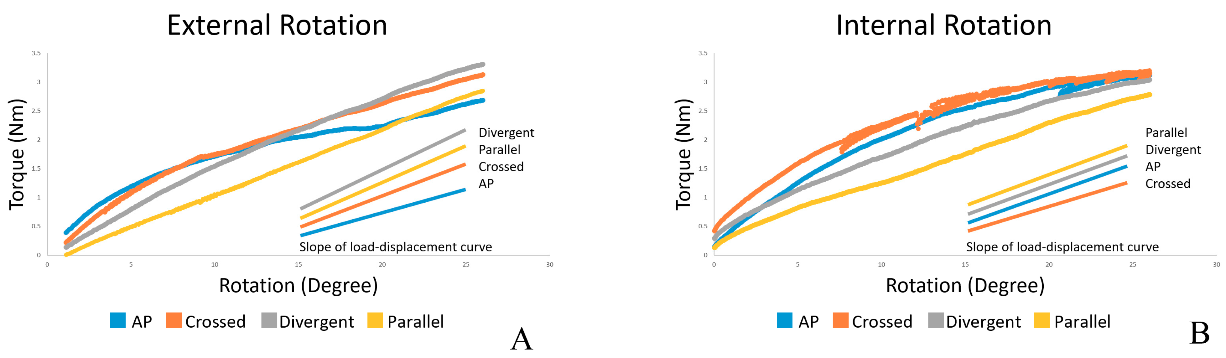
| Internal rotation (Nm/deg) | 0.085 ± 0.006 | 0.073 ± 0.006 | 0.093 ± 0.020 | 0.098 ± 0.010 | 0.134 |
| External rotation (Nm/deg) | 0.063 ± 0.008 | 0.093 ± 0.017 | 0.120 ± 0.012 | 0.115 ± 0.010 | 0.002 |
| External Rotation (Nm/deg) | AP | Crossed | Divergent |
|---|---|---|---|
| Crossed | p = 0.096 | ||
| Divergence | p = 0.003 | p = 0.165 | |
| Parallel | p = 0.005 | p = 0.359 | p = 1.000 |
Publisher’s Note: MDPI stays neutral with regard to jurisdictional claims in published maps and institutional affiliations. |
© 2021 by the authors. Licensee MDPI, Basel, Switzerland. This article is an open access article distributed under the terms and conditions of the Creative Commons Attribution (CC BY) license (https://creativecommons.org/licenses/by/4.0/).
Share and Cite
Pothong, W.; Phinyo, P.; Sirirungruangsarn, Y.; Nabudda, K.; Wongba, N.; Sarntipiphat, C.; Pruksakorn, D. Biomechanical Analysis of Sagittal Plane Pin Placement Configurations for Pediatric Supracondylar Humerus Fractures. Appl. Sci. 2021, 11, 3447. https://0-doi-org.brum.beds.ac.uk/10.3390/app11083447
Pothong W, Phinyo P, Sirirungruangsarn Y, Nabudda K, Wongba N, Sarntipiphat C, Pruksakorn D. Biomechanical Analysis of Sagittal Plane Pin Placement Configurations for Pediatric Supracondylar Humerus Fractures. Applied Sciences. 2021; 11(8):3447. https://0-doi-org.brum.beds.ac.uk/10.3390/app11083447
Chicago/Turabian StylePothong, Witit, Phichayut Phinyo, Yuddhasert Sirirungruangsarn, Kriengkrai Nabudda, Nattamon Wongba, Chatchawarl Sarntipiphat, and Dumnoensun Pruksakorn. 2021. "Biomechanical Analysis of Sagittal Plane Pin Placement Configurations for Pediatric Supracondylar Humerus Fractures" Applied Sciences 11, no. 8: 3447. https://0-doi-org.brum.beds.ac.uk/10.3390/app11083447