
Research on a Low Melting Point Al-Si-Cu (Ni) Filler Metal for 6063 Aluminum Alloy Brazing
by

Chengyin Peng
1,2, 
Dandan Zhu
3,
Kaifeng Li
3,
Xiang Du
1,2,
Fei Zhao
1,2,*,
Mingpan Wan
1,2 and
Yuanbiao Tan
1,2 1
College of Materials and Metallurgy, Guizhou University, Guiyang 550025, China
2
Key Laboratory for Materials Structure and Strength of Guizhou province, Guiyang 550025, China
3
Guizhou Yonghong Heat Transfer & Cooling Technology Co., Ltd., Huishui 550600, China
*
Author to whom correspondence should be addressed.
Appl. Sci. 2021, 11(9), 4296; https://0-doi-org.brum.beds.ac.uk/10.3390/app11094296
Submission received: 21 April 2021
/
Revised: 4 May 2021
/
Accepted: 7 May 2021
/
Published: 10 May 2021
(This article belongs to the Topic Metallurgical and Materials Engineering)
Abstract
:Featured Application
Research on a Low-Melting-Point Solder for a 6063 Aluminum Alloy Cold Plate Radiator.
Abstract
A new type of low melting point Al-Si-Cu (Ni) filler metal for brazed 6063 aluminum alloy was designed, and the microstructure and properties of the filler metal were systematically studied. The results show that when the content of Cu in the Al-Si-Cu filler metal increased from 10 wt.% to 20 wt.%, the liquidus temperature of the filler metal decreased from 587.8 °C to 533.4 °C. Its microstructures were mainly composed of the α-Al phase, a primary Si phase, and a θ(Al2Cu) phase. After a proper amount of Ni was added to the Al-Si-20Cu filler metal, its melting range was narrowed, the spreading wettability was improved, and the microstructure was refined. Its microstructure mainly includes α-Al solid solution, Si particles, and θ(Al2Cu) and δ(Al3Ni2) intermetallic compounds. The results of the shear strength test indicate that the shear strength of the brazed joint with Al-6.5Si-20Cu-2.0Ni filler metal was 150.4 MPa, which was 28.32% higher than that of the brazed joint with Al-6.5Si-20Cu filler metal.
1. Introduction
Brazing holds the advantages of low deformation of the weldment, high dimensional accuracy, and high production efficiency. Brazing is one of the commonly used connection methods for heat exchangers [1,2,3]. As a light alloy material with excellent weldability and heat conductivity, 6063 aluminum alloy can be used as the main material of the heat exchanger [4,5,6]. Al-Si system filler metal is typically used in the brazing of aluminum and its alloys. The content of Si is 7~13 wt.%, and the liquidus temperature is approximately 570 °C [7,8]. To obtain excellent brazed joints, the brazing temperature must be higher than 595 °C, which is close to the solid phase temperature of 6063 aluminum alloy (approximately 615 °C), which may cause base metal grain growth or over-burning [2,4,7]. In addition, an excessive brazing temperature not only enhances the manufacturing cost but also causes dissolution of the base metal, and the quality of the brazed joint obtained is poor [5,9]. Therefore, it is becoming increasingly important to develop a new type of low melting point, aluminum-based filler metal for low-cost and high-quality aluminum alloy brazed joints.
To solve the problem of an excessively high brazing temperature, in recent years, many researchers have developed a series of new low melting point, aluminum-based filler metals by alloying methods with the theoretical support of eutectic components of Al-Si, Al-Cu, Al-Ge, Al-Zn, etc., and the corresponding properties have been studied [2,7,10,11,12]. The addition of Ge to the Al-Si filler metal can narrow the melting point of the Al-Si-Ge filler metal, but the melting range of the filler metal will widen with increasing Ge content, and the fluidity of the filler metal will decrease. In addition, Ge is costly; as a result, Al-Si-Ge filler metal is not suitable for large-scale applications [10]. Dai et al. [8,11] studied the Al-6.5Si-42Zn filler metal, the melting range of which was found to be 27.7 °C. When it was used to braze 6061 aluminum alloys, the joint tensile-strength was improved to 129 MPa compared with Al-Si filler metal. However, the content of Zn in Al-Si-Zn filler metal is too high, which easily causes the dissolution of the base metal and reduces the strength of the brazed joint. Moreover, the vapor pressure of Zn is too high, which may have adverse effects on the vacuum–brazing process [13]. Al-Si-Cu filler metal has the benefits of a low melting point and good wettability, which is a hot research direction of aluminum alloy filler metals [4,5,7]. Chang et al. [7] studied the brazing of 6061 aluminum alloy with Al-10.8Si-10Cu and Al-9.6Si-20Cu filler metals at 560 °C, and found that there are more θ(Al2Cu) brittle phases in the brazed joints, leading to a lower shear strength of the brazed joints (47 MPa and 67 MPa, respectively). The results indicate that adding an appropriate amount of Ni to Al-Si-Cu filler metal can replace part of the Cu and reduce the adverse effect of θ(Al2Cu) on joint properties [4,5,14]. Luo et al. [4] developed Al-10Si-15Cu-4Ni filler metal with a melting range of 24.9 °C and successfully brazed 6061 aluminum alloy at 570 °C. Meanwhile, the joint shear strength was as high as 144.4 MPa, which was higher than that of Al-Si-Cu brazing filler metal [2,7]. However, Al-Si-Cu filler metal still has the problems of a wide melting interval and a low shear strength of the brazed joint, which urgently needs to be solved.
Based on the pseudoeutectic point composition of Al-Si-Cu ternaries [15], a new type of Al-Si-Cu (Ni) multicomponent aluminum-based filler metal with a low melting point and a narrow melting interval was developed. The optimal Al-Si-Cu (Ni) filler metal was obtained by a comprehensive analysis after studying the melting characteristics, the spreading wettability, the microstructure, and the brazeability of different Al-Si-Cu (Ni) filler metals. Its properties have been significantly improved compared with those of existing filler metals.
2. Materials and Methods
The base material used in this experiment was 6063 aluminum alloy plates with a thickness of 1 mm. Its chemical composition is listed in Table 1. The melting temperature of the base metal was approximately 617.8~657.7 °C, and the tensile strength at room temperature was 257.94 MPa. A series of Al-Si-Cu and Al-Si-Cu-Ni filler metals were prepared using the master alloys Al-50Cu (≥99.970 wt.%), Al-30Si (≥99.970 wt.%), and Al-10Ni (≥99.000 wt.%) and high-purity aluminum particles (≥99.900 wt.%) as raw materials, which were melted in a well-type resistance furnace covered with molten salt with a mass ratio of NaCl:KCl = 1:1. Hexachloroethane was used the refining agent. The nominal compositions of the investigated filler metal are listed in Table 2. To ensure the compositional uniformity of the brazing alloys, each group was remelted twice, and the obtained castings were heat-retained at 450 °C for 12 h for the diffusion annealing treatment.
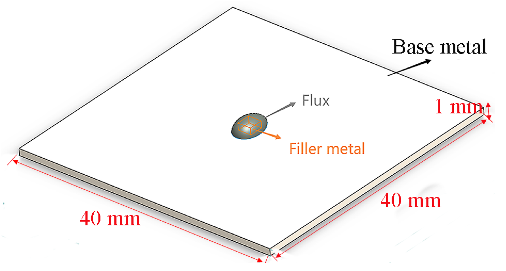
The melting temperature of the filler metal was determined by differential thermal analysis (DTA, TG/DTA7300, Japan). The filler metal was heated from room temperature to 700 °C under an argon atmosphere at a heating rate of 10 °C/min. The fluidity and wettability of filler metals were assessed by wetting experiments. After the filler metals with a size of 3 mm × 3 mm × 3 mm were weighed, they were placed at the center of the base material 6063 aluminum alloy (40 mm × 40 mm × 1 mm) and completely covered with QJ201 flux (with a melting range of 460~520 °C) (Figure 1). The process parameter of the spreading test was 570 ± 3 °C for 5 min. The spread sample was washed with warm water (50~60 °C), photographed with a camera, and imported into Image-Pro Plus to measure the spreading area of the filler metals. The results were averaged by the spreading area per unit mass.
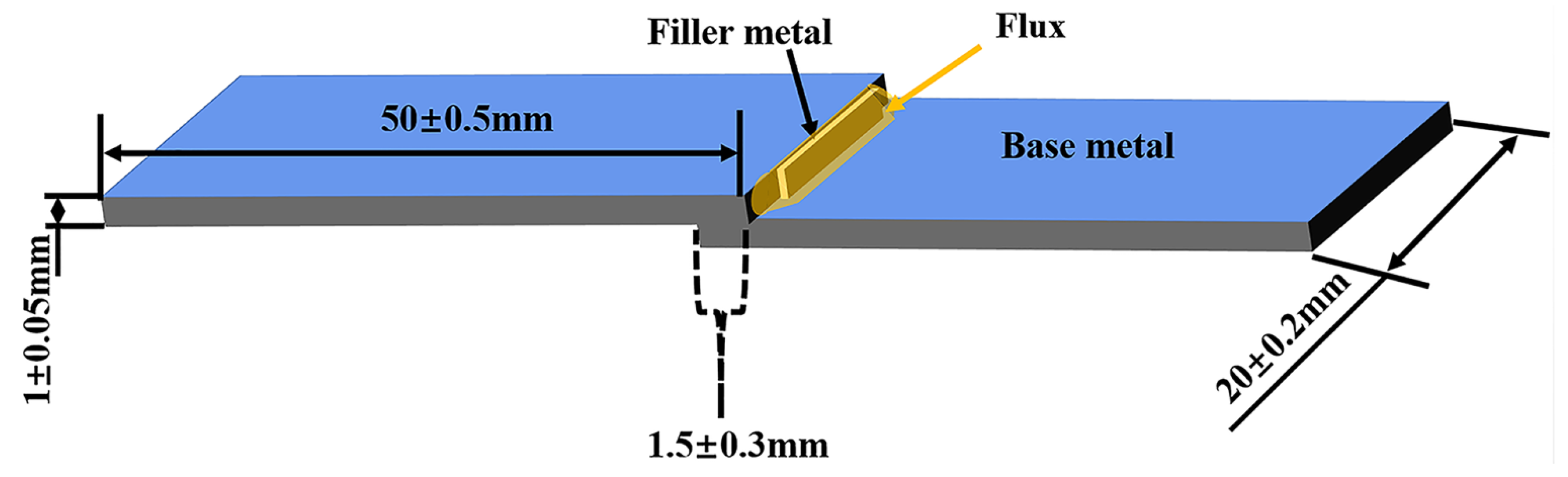
The brazing experiment was completed in a box-type resistance furnace. A schematic illustration of the brazed joint is shown in Figure 2. The specification of the base material was 50 mm × 20 mm × 1 mm, the specification of the filler metal was 15 mm × 1 mm × 0.2 mm, the lap length of the joint was 1.5 mm ± 0.3 mm, the gap was 0.1 ± 0.05 mm, and the flux used for brazing was QJ201. Before brazing, the surface of the base metal and the filler metal was polished with sandpaper. After the acetone was degreased, the surface oxide film was removed with a 10% NaOH solution and then neutralized with a 10% HNO3 solution. Finally, the samples were cleaned with ethanol, dried, and assembled. The brazing technological parameters were as follows: raise the furnace temperature to 570 °C, put the prepared sample into the furnace after the furnace temperature becomes stable, keep the temperature at 570 °C for 10 min, stop heating, open the furnace door to take out the sample for air cooling when the furnace temperature drops to approximately 500 °C, and finally clean the sample repeatedly with hot water (50~60 °C) to remove the flux residue. Two step-aging treatments were adopted to improve the mechanical properties of the brazed parts. The heat treatment system was as follows: after solid solution treatment (530 °C × 3 h) and room temperature water quenching of the brazed parts, the brazed parts were immediately subjected to primary aging (160 °C × 1 h) and water cooling, Finally, the brazed parts were subjected to secondary aging for 3 h at 190 °C and water cooling.
The microstructures of the filler metals were analyzed by an X-ray diffractometer (XRD, Cu Kα, Empyrean, Holland). The scanning angle was 10° to 90°, the scanning rate was 0.188°/s, the accelerating voltage was 45 kV, and the working current was 40 mA. The shear strength of a brazed joint was measured on an Instron 8501 universal testing machine at a tensile speed of 0.5 mm/min. To ensure the accuracy of the results on the shear strength of the brazed joints, three specimens were brazed under the same conditions with each filler metal, and the average values of the test results were calculated. The micro-Vickers hardness of brazed joints was measured by an MHV-2.0 automatic microhardness tester, three points were measured in each area, and the average value of the results was taken. Scanning electron microscopy (SEM. SUPRA 40, Germany) and energy dispersive spectrometry (EDS) were used to observe the microstructure of the filler metals and brazed joints after etched in a mixture of 1vol.% HF, 1.5 vol.% HCl, 2.5 vol.% HNO3 and 95 vol.% H2O at room temperature for 20 s.
3. Results and Discussion
3.1. Melting Characteristics of the Al-Si-Cu (Ni) Filler Metal
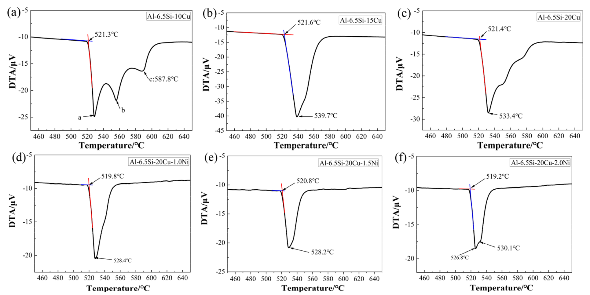
Figure 3 shows the melting characteristics of filler metals with different Cu and Ni contents. The melting temperatures of the filler metals in this study, determined according to the DTA curve in Figure 3, are summarized in Table 2. Combined with Table 2 and the Figure 3 analysis, when the Cu content was reduced from 10 wt.% to 20 wt.%, the liquidus temperatures of Al-Si-Cu alloys decreased from 587.8 °C to 533.4 °C, the solidus temperature had no significant effects, and the melting temperature ranges of Al-6.5Si-(10, 15, 20) Cu filler metals gradually became narrower (66.5 °C, 18.1 °C, and 12.0 °C, respectively). With increasing Cu content, the composition of the Al-Si-Cu filler metal gradually approached the eutectic composition point of the Al-Si-Cu ternary alloy, noncongruent melting gradually changed into congruent melting, thus reducing the melting temperature range [15]. It can be seen from Figure 3 that the DTA curve of the Al-6.5Si-10Cu filler metal was similar to that in previous research [4,7]; it was not a single endothermic peak but a certain number of endothermic peaks, and the corresponding temperatures were a: 528.5 °C, b: 552.4 °C, and c: 587.8 °C. According to the Al-Si-Cu, Al-Cu, and Al-Si phase diagram [16,17,18], it was inferred that endothermic peak a was related to the reverse reaction of the L→α(Al) + Si + θ(Al2Cu) reaction, and endothermic peaks b and c were relatively smooth, which was presumed to be related to the Al-Cu eutectic and Al-Si eutectic reactions.
When 1.0 wt.%, 1.5 wt.%, and 2.0 wt.% Ni were added to the ternary filler metal Al-6.5Si-20Cu, the solidus temperatures of the filler metals did not change obviously, but the liquidus temperature was somewhat reduced. The solidus and liquidus temperatures of the Al-Si-Cu-Ni alloys were 519.8~528.4 °C, 520.8~528.2 °C, and 519.2~526.8 °C, respectively. Because the addition of Ni introduces a novel low melting temperature alloy reaction, the reverse reaction of L→α(Al) + Si was inhibited, and the liquidus temperature of the brazing alloy was reduced [18]. The composition of the Al-6.5Si-20Cu-2.0Ni filler metal was close to the eutectic point of the Al-Si-Cu-Ni quaternary alloy, so the DTA curve of the filler metal was relatively gentle between 526.8 and 530.1 °C [4,15,19], and the melting temperature range of Al-Si-Cu-Ni filler metals was narrower than that of Al-Si-Cu. Compared with previous scholars’ research on Al-10Si-15Cu-4Ni(ΔT = 24.9 °C) [4], Al-8.5Si-25Cu-1.5Ni-0.2Re(ΔT = 18.0 °C) [5], Al-10.8Si-10Ge(ΔT = 61.0 °C) [10] and Al-6.5Si-42Zn-Sr (ΔT = 28.1 °C) [11], the melting temperature ranges of the Al-6.5Si-20Cu, and Al-6.5Si-20Cu-(1.0, 1.5, 2.0) Ni filler metals were narrower, which will facilitate the filling of the joint gaps with the liquid filler metals during the brazing process [4,20].
3.2. Effect of Cu and Ni on the Microstructure of Al-Si-Cu (Ni) Filler Metals
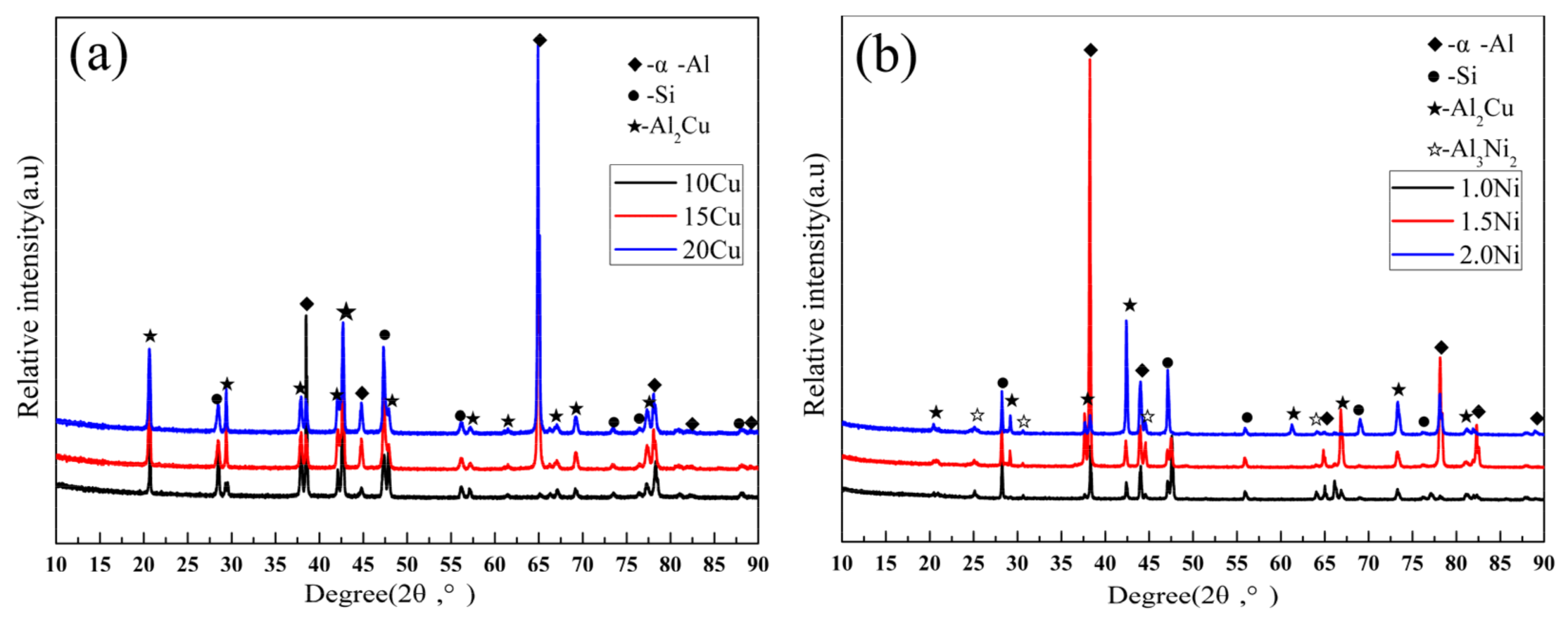
The microstructures of the filler metals were analyzed by SEM, XRD, and EDS. Figure 4 shows the XRD patterns of Al-Si-Cu alloys and Al-Si-Cu-Ni alloys. The XRD results show that the Al-6.5Si-(10, 15, 20) Cu were mainly composed of the α-Al phase, a Si phase, and a θ(Al2Cu) phase. The Al-6.5Si-20Cu-(1.0, 1.5, 2.0) Ni were mainly composed of the α-Al phase, a Si phase, a θ(Al2Cu) phase, and δ-Al3CuNi (Al3Ni2).
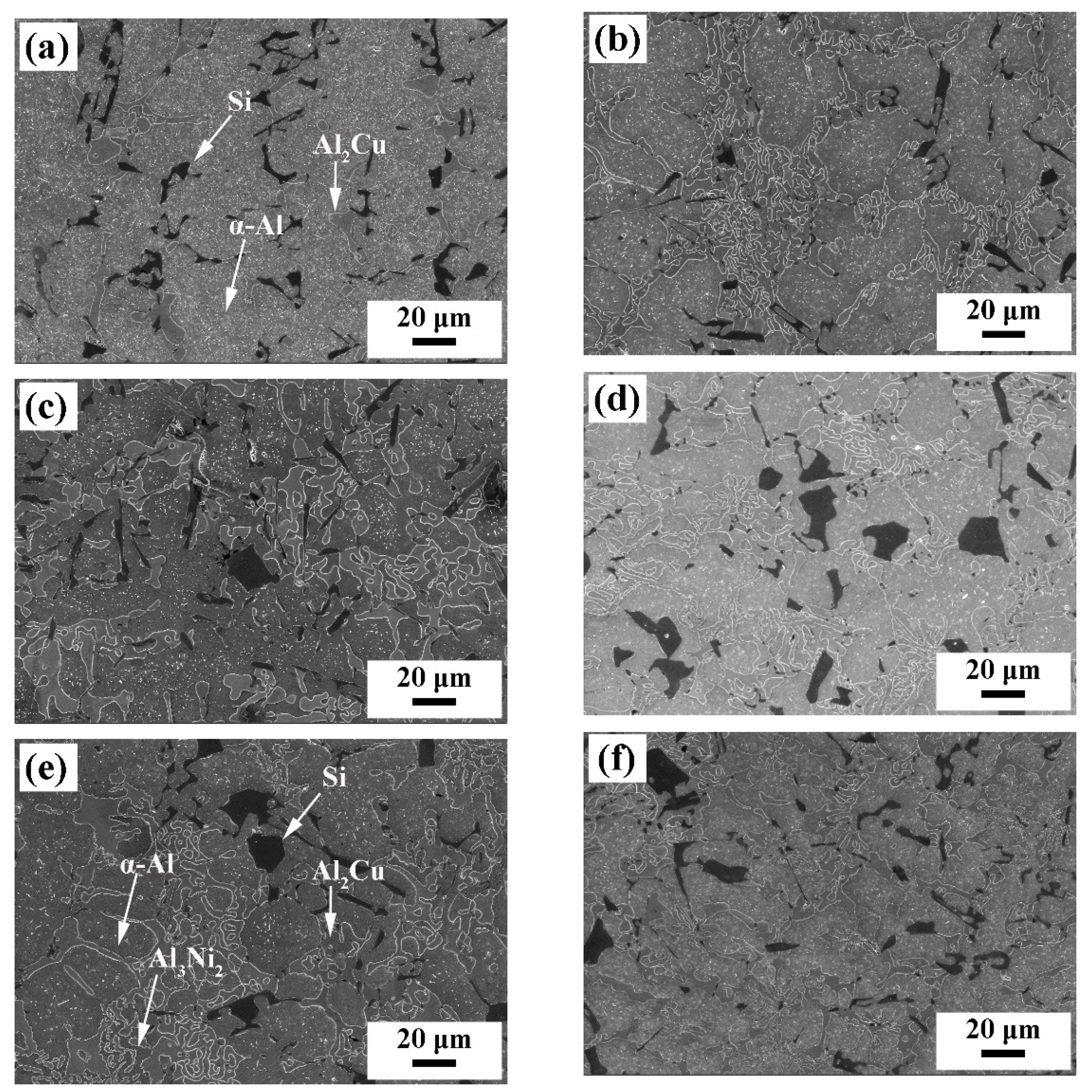
Figure 5 shows the SEM images of the filler metals. Figure 5a–c indicates that the Al-6.5Si-(10, 15, 20) Cu filler metals are composed of the α-Al solid solution phase, bulk primary Si, and a θ(Al2Cu) intermetallic compound. With increasing Cu content, the number of θ(Al2Cu) phases gradually increases, and the size gradually increases. According to Figure 5d–f, the Al-6.5Si-20Cu-(1.0, 1.5, 2.0) Ni filler metals had reticular structure, and the reticular solid solution phase was the δ(Al3Ni2) phase according to the EDS analysis and XRD patterns [21,22]. With increasing Ni content, the number of bulk primary Si phases decreased, part of the Si phase was refined, showing a fibrous structure, and the brittle θ(Al2Cu) phase gradually transformed from a bulk to a lamellar-type structure, as shown in Figure 5d–e.
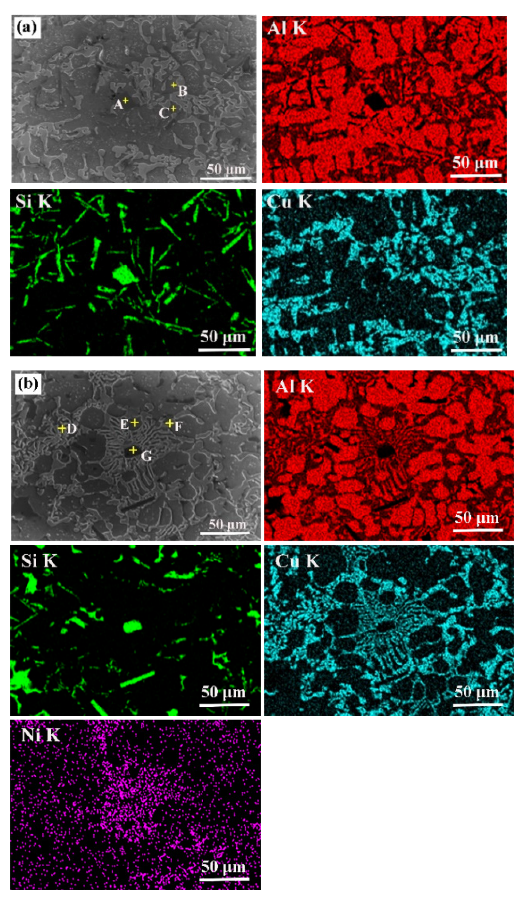
To further analyze the elemental distribution of the filler metals and the influence of Ni on the microstructure of the Al-Si-Cu filler metals, an EDS surface scanning analysis was carried out on the microstructures of the Al-6.5Si-20Cu and Al-6.5Si-20Cu-1.5Ni filler metals. The EDS element mapping are shown in Figure 6, and the EDS results are shown in Table 3. The EDS analysis showed that A and G were mainly Si phases, C and E were mainly α-Al phases, B and D were mainly Al2Cu phases, and F was mainly a δ(Al3Ni2) phase. The element distribution diagram indicates that part of the Si phase was embedded in the α-Al phase, and part of the Cu was replaced by Ni in the θ(Al2Cu) phase region, causing the local intermetallic compound θ(Al2Cu) to change from elongated to discontinuous. The blade shape can effectively reduce the adverse effect of the intermetallic compound θ(Al2Cu) on the solder alloy.
3.3. Wettability of Al-Si-Cu (Ni) Filler Metal on Substrates
The fluidity of the filler metal was one of the factors affecting the quality of brazed joints, and the spreading area of the brazing alloy on the base material can well reflect the wetting and flowing joint-filling ability of brazing filler metal. The effects of different Cu and Ni contents on the spreading properties of the Al-Si-Cu and Ni filler metals are shown in Table 4. The spreading area per unit mass of Al-Si-(10, 15, 20) Cu filler metals increased from 0.58 cm2 to 2.87 cm2. Compared with the Al-6.5Si-20Cu filler metal, the spreading area per unit mass of Al-6.5Si-20Cu-(1.0, 1.5, 2.0) Ni filler metals increased by 12.5%, 8.0%, and 6.8%, respectively. When 2.0 wt.% Ni was added, the liquidus temperature of the filler metal increased, the melting range became wider, and the spreading ability decreased, which may be due to the formation of more complex alloy compounds between Ni and Al, which affected the fluidity of the filler metal [21,22,23].
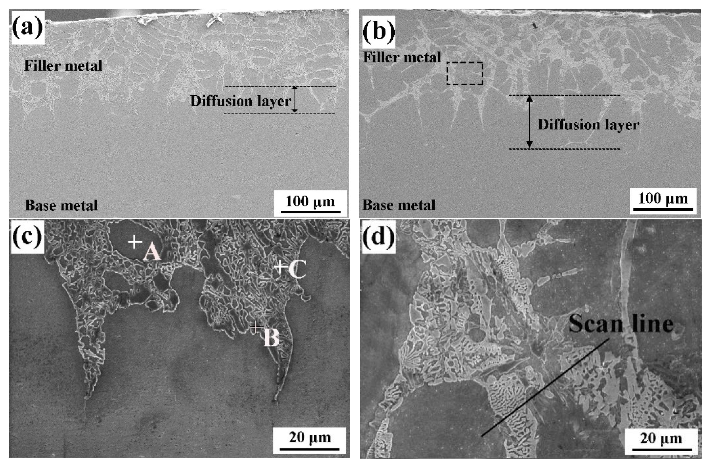
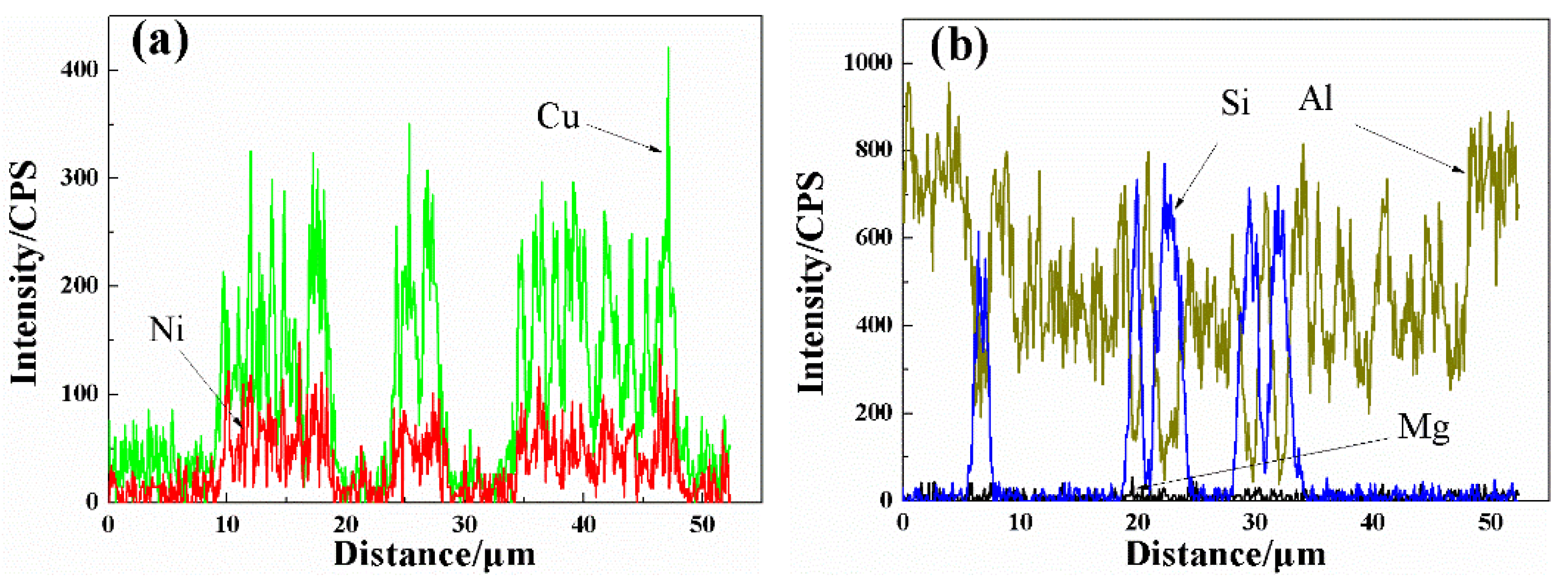
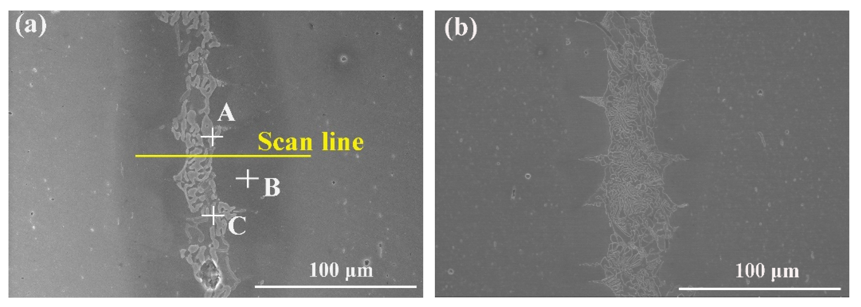
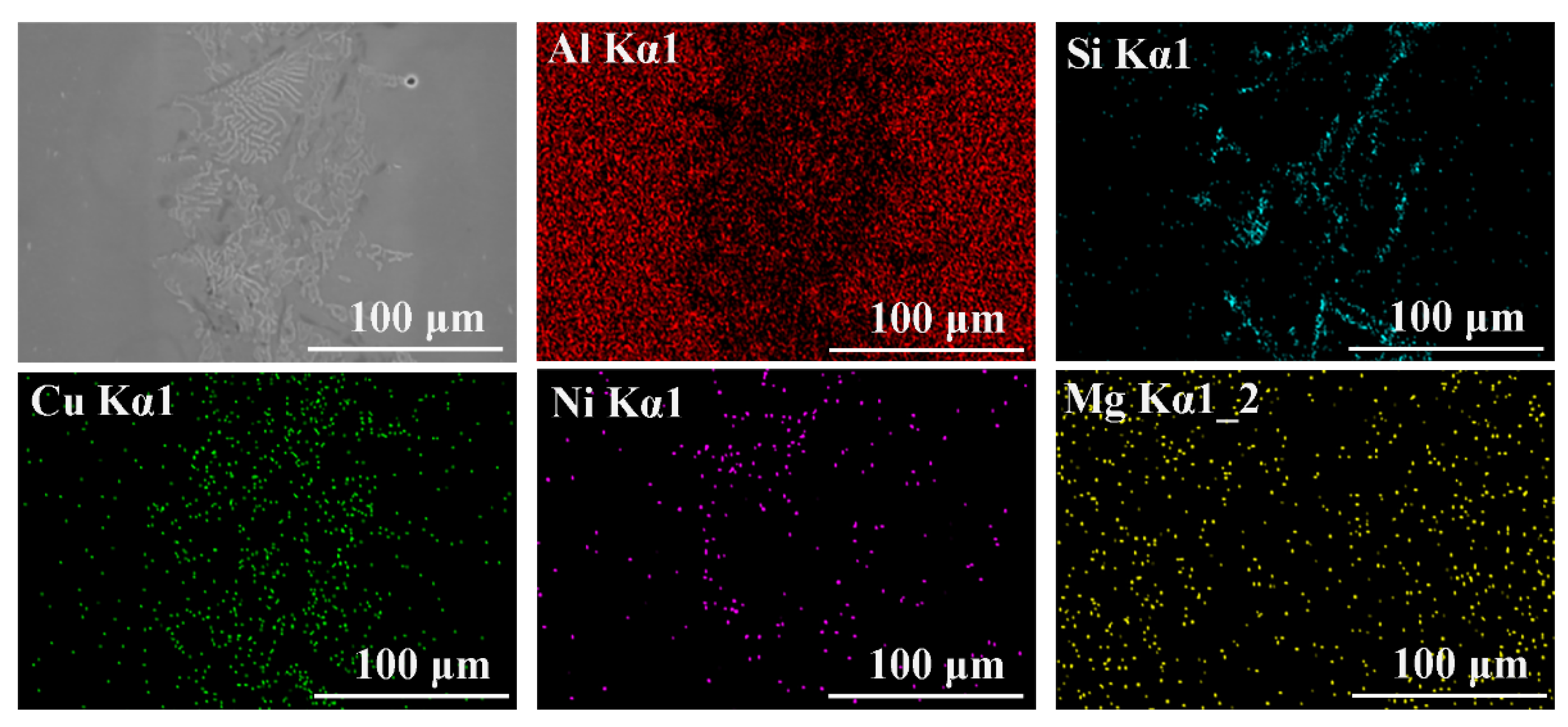
Figure 7 shows the microstructures of the spreading interface of the Al-6.5Si-20Cu/base material and the Al-6.5Si-20Cu-1.5Ni/base material. According to Fick’s law of diffusion, there was a large concentration difference between the filler metal and the base metal; therefore, Cu in the filler metal diffused into the base metal along the grain boundaries and reacted with Al in the base material to form θ(Al2Cu) intermetallic compounds. The base materials interlaced with each other at the spreading interface, forming a diffusion layer between the filler metal and the base material. The microstructures of the spreading interface in Figure 7c,d were analyzed by EDS, and the results are shown in Table 5 and Figure 8. Table 5 shows that the microstructure of the Al-6.5Si-20Cu filler metal/Al spreading interface was mainly composed of three phases: the α–Al phase, a θ (Al2Cu) phase, and a Si phase. Figure 8 shows that Ni replaced a certain amount of Cu in the microstructure of the Al-6.5Si-20Cu-1.5Ni filler metal/Al spreading interface such that the Cu and Ni are interlaced, which weakened the influence of Cu on the brittleness of the brazed alloys. Therefore, the addition of Ni can not only advance the interdiffusion of elements between the filler metal and the base metal, but also refine the grains and improve the performance of the filler metal.
3.4. Brazeability of 6063 Aluminum Alloy with Al-Si-Cu (Ni) Filler Metal
Figure 9 shows the microstructure of the aluminum alloy brazed joints after heat treatment strengthening. The microstructures of the brazed joints were compact and showed good metallurgical bonding. Table 6 shows the results of the EDS analysis of the six points marked in Figure 9a,c. It can be concluded that the microstructure of the Al-6.5Si-20Cu brazed joint was mainly composed of the α-Al phase, a coarse θ(Al2Cu) phase, and a Si phase. There was a small amount of Al2Cu intermetallic compound at the brazed joint interface, and some Si particles were embedded in the matrix [14,24]. Figure 9b–d show the microstructure diagrams of Al-6.5Si-20Cu-Ni brazed joints. The addition of Ni produces the δ(Al3Ni2) phase, which makes the Al2Cu at the brazing seams transition from a bulk to a lamellar-type structure, and the microstructure distribution of the joints is more monotonous. Figure 10 shows the line scan distribution diagram of the elements in Figure 9a. In the brazing process, Cu and Si were enriched at the interface between the brazing seam and the base metal, and the post-welding heat treatment promoted the interdiffusion between atoms, so the contents of Al and Mg at the interface of the brazing seam were significantly reduced [4,11]. Figure 11 shows a schematic diagram of the surface scanning consequences of the microstructure of Al-6.5Si-20Cu-1.5Ni-brazed 6063 aluminum alloy joints. Cu and Ni were uniformly distributed in the central area of the brazing seams, the segregation of Si was reduced, which was conducive to reducing the Si phase, and the θ(Al2Cu) phase influenced the brittleness of the brazed joints. The results of the EDS analysis (Table 6) show that the Si and Cu contents at B and F were higher than those of the base material at the joint interface, which indicates that during the brazing process of Al-Si-Cu (Ni) filler metals and 6063 aluminum alloy, the elements between the liquid solder and the base metal diffused, forming a diffusion layer. The post-weld heat treatment enhanced the diffusion of elements and effectively promoted the metallurgical bonding reaction between the filler metal and the base metal [20].
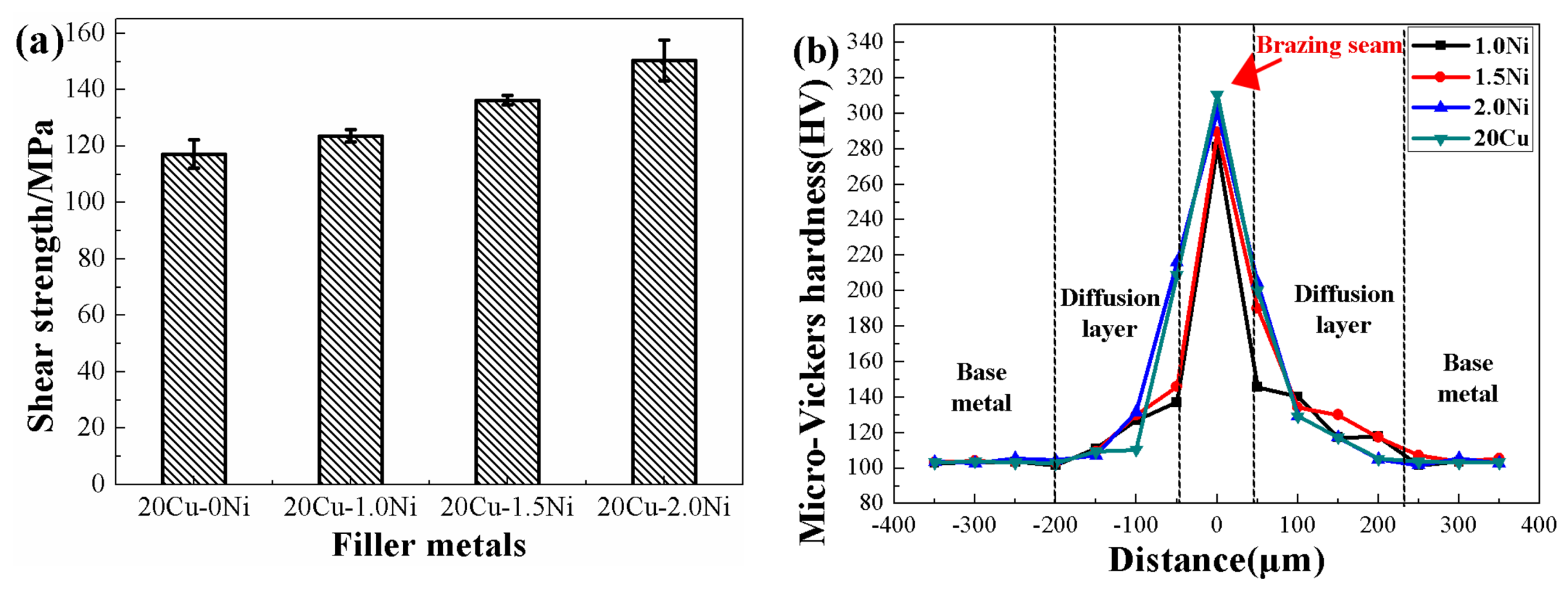
Figure 12a shows that the shear strength of the Al-6.5Si-20Cu brazed joint was approximately 117.2 MPa, and the shear strength of the Al-6.5Si-20Cu-(1.0, 1.5, 2.0) Ni brazed joints gradually increased with the increase in Ni content to 123.6 MPa, 136.3 MPa, and 150.4 MPa, compared with the Al-6.5Si-20Cu brazed joints whose shear strength increased by 5.46%, 16.30%, and 28.32%, respectively. Compared with the joint shear strength (62.6 MPa) obtained by brazing 6063 aluminum alloy with the Al-8.5Si-25Cu-1.5Ni-0.2Re filler metal studied by Zhang et al. [5], the shear strength (136.3 MPa) of the joint brazed with the Al-6.5Si-20Cu-1.5Ni filler metal developed in this experiment increased by 117.73%. Figure 12b shows the microhardness curve of the brazed joints. There were Al2Cu intermetallic compounds and primary Si in the brazed seam center area of the weld [2,7,25], and the hardness of this zone was 281~310 HV. During the brazing process, the elements between the filler metal and the base metal diffused to form a diffusion zone whose hardness was slightly higher than that of the base metal. The hardness of the interface area of the brazed seam was 107~216 HV, and the hardness of the base metal was 102~105 HV. Therefore, the microhardness of the brazing seam appears to decrease from the brazed seam center area to the base metal.
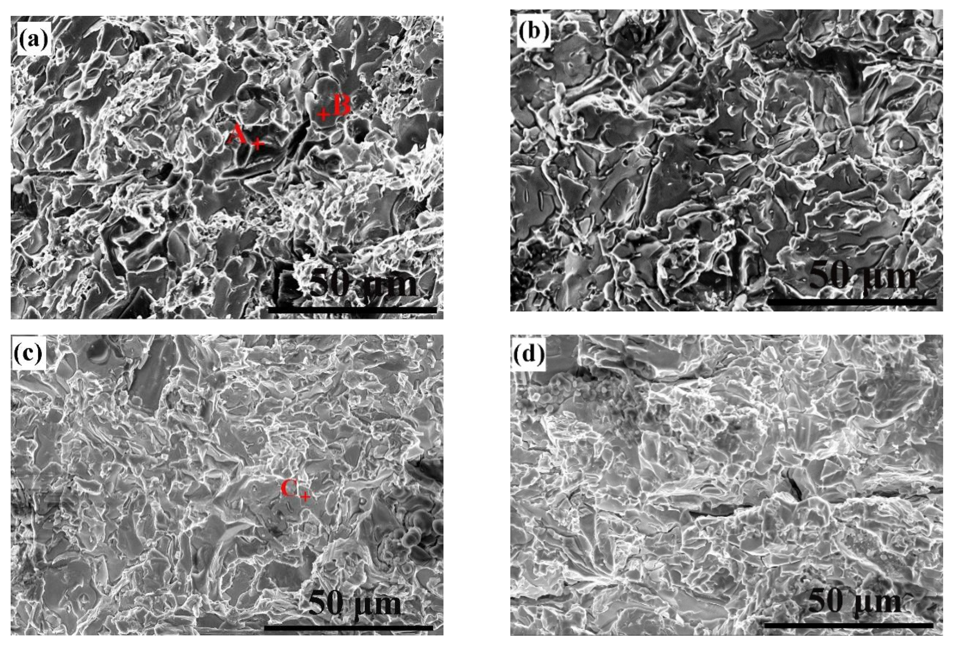
Figure 13 shows the shear fracture morphology of 6063 aluminum alloy joints brazed with Al-Si-20Cu and Al-6.5Si-20Cu-(1.0, 1.5, 2.0) Ni filler metals. The fracture morphology of the brazed joints indicates the characteristics of brittle fracture. Table 7 lists the results of the EDS analysis of the typical phases of the fracture morphology of Al-Si-Cu (Ni) brazing joints. The results show that A, B, and C were the primary Si phase, the θ(Al2Cu) phase, and the θ(Al2Cu) + δ(Al3Ni2) phase, respectively. In the process of brazing, elements in the matrix and liquid filler metal inter-diffused, so that the filler metal and the base metal had a better metallurgical bond. A small amount of Mg was detected in the joint fracture, so it can be judged that the fracture location of the brazed joint was roughly in the interface area of the brazed seam.
Based on the analysis of the microstructure, shear strength, and shear fracture morphology of the joint, when Al-6.5Si-20Cu brazed the 6063 aluminum alloy, there was a large θ(Al2Cu) brittle phase in the brazing seam, but the large θ(Al2Cu) phase had poor compatibility with the substrate deformation, the strain was concentrated at the phase interface, the crack initiation near the θ(Al2Cu) phase was accelerated, and the fracture of the welded joint was accelerated, so the shear fracture of the brazed joint was a smooth and typical brittle fracture. When 6063 aluminum alloy was brazed with the Al-6.5Si-20Cu-Ni filler metal, the existence of Ni not only made the brittle phase of the Al2Cu finer and more dispersed but also improved the deformation coordination of the θ(Al2Cu) phase and matrix and the shear strength of the brazed joint, reduced the strain concentration degree, and presented a mixed fracture mode.
4. Conclusions
In this paper, a new low-melting-point Al-Si-Cu (Ni) filler metal was designed and prepared. The melting characteristics, microstructure, and spreading wettability of the filler metal were researched and the microstructure and mechanical properties of the joint brazed with 6063 aluminum alloy were studied. The conclusions can be summarized as follows:
(1) The Al-Si-Cu filler metal was mainly composed of α-Al solid solution, a θ(Al2Cu) intermetallic compound, and bulk primary Si. With increasing Cu, the melting temperature of the Al-Si-Cu filler metal decreased, the melting interval became narrower, and the spreading performance improved. The melting range of the Al-6.5Si-20Cu filler metal was 521.4~533.4 °C, and the spreading area per unit mass was 2.87 cm2.
(2) The Al-Si-Cu-Ni filler metal was mainly composed of α-Al solid solution, a θ(Al2Cu) intermetallic compound, bulk primary Si, and a δ(Al3Ni2) intermetallic compound. The addition of Ni not only narrowed the melting range of the Al-Si-Cu filler metal but also transformed the coarse, brittle Al2Cu phase from a bulk to a lamellar-type structure, and the structure was refined. With increasing Ni content, the spreading ability of the Al-Si-Cu-Ni filler metal decreased. The melting ranges of the Al-Si-Cu-Ni solder were 8.6 °C, 7.7 °C, and 7.6 °C, and the spreading areas per unit mass were 3.28 cm2, 3.12 cm2, and 3.02 cm2, respectively.
(3) When Al-6.5Si-20Cu and Al-6.5Si-20Cu-(1.0, 1.5, 2.0) Ni filler metals were used to braze 6063 aluminum alloy at 570 °C for 10 min, brazing joints with shear strengths of 117.2 MPa, 123.6 MPa, 136.3 MPa, and 150.4 MPa were obtained. Therefore, the addition of Ni can effectively increase the shear strength of the brazed joints.
Author Contributions
Conceptualization, C.P. and F.Z.; methodology, C.P. and F.Z.; software, C.P. and F.Z.; validation, C.P., F.Z., and X.D.; formal analysis, C.P. and F.Z.; investigation, D.Z. and K.L.; resources, M.W. and Y.T.; data curation, C.P. and X.D.; writing—original draft preparation, C.P.; writing—review and editing, C.P.; visualization, X.D.; supervision, D.Z. and K.L.; project administration, M.W. and Y.T.; funding acquisition, F.Z. All authors have read and agreed to the published version of the manuscript.
Funding
This research was funded by the key special project of “Science and Technology Boost Economy 2020” of the Ministry of Science and Technology of China and the Science and Technology Program of Guizhou Province with Grant Nos. 20194106 and 20165654, 2021109.
Institutional Review Board Statement
Not applicable.
Informed Consent Statement
Not applicable.
Data Availability Statement
Not applicable.
Conflicts of Interest
The authors declare no conflict of interest.
References
- Niu, Z.; Huang, J.; Liu, K.; Xu, F.; Chen, S.; Zhao, X. Brazing of 6061 aluminum alloy with the novel Al-Si-Ge-Zn filler metal. Mater. Lett. 2016, 179, 47–51. [Google Scholar] [CrossRef]
- Pei, C.; Wu, X.; Zhang, G.; Cheng, Y.; Ren, X.; Wang, W.; Xiong, H. Microstructures and mechanical properties of brazed 6063 aluminum alloy joint with Al-Cu-Si-Ni filler metal. Weld. World 2020, 64, 1933–1938. [Google Scholar] [CrossRef]
- Simões, S. Diffusion Bonding and Brazing of Advanced Materials. Matals 2018, 8, 959. [Google Scholar] [CrossRef] [Green Version]
- Luo, W.; Wang, L.T.; Wang, Q.M.; Gong, H.L.; Yan, M. A new filler metal with low contents of Cu for high strength aluminum alloy brazed joints. Mater. Des. 2014, 63, 263–269. [Google Scholar] [CrossRef]
- Zhang, G.; Bao, Y.; Jiang, Y.; Zhu, H. Microstructure and Mechanical Properties of 6063 Aluminum Alloy Brazed Joints with Al-Si-Cu-Ni-RE Filler Metal. J. Mater. Eng. Perform. 2011, 20, 1451–1456. [Google Scholar] [CrossRef]
- Lacaze, J.; Tierce, S.; Lafont, M.C.; Thébault, Y.; Pébère, N.; Mankowski, G.; Blanc, C.; Robidou, H.; Vaumousse, D.; Daloz, D. Study of the microstructure resulting from brazed aluminium materials used in heat exchangers. Mater. Sci. Eng. A 2005, 413, 317–321. [Google Scholar] [CrossRef] [Green Version]
- Chang, S.Y.; Tsao, L.C.; Li, T.Y.; Chuang, T.H. Joining 6061 aluminum alloy with Al–Si–Cu filler metals. J. Alloy. Compd. 2009, 488, 174–180. [Google Scholar] [CrossRef]
- Dai, W.; Xue, S.; Lou, J.; Wang, S. Development of Al–Si–Zn–Sr filler metals for brazing 6061 aluminum alloy. Mater. Des. 2012, 42, 395–402. [Google Scholar] [CrossRef]
- Wei, D.; Songbai, X.; Bo, S.; Jiang, L.; Suiqing, W. Study on Microstructure of 6061 Aluminum Alloy Brazed with Al-Si-Zn Filler Metals Bearing Sr and Ti. Rare Met. Mater. Eng. 2013, 42, 2442–2446. [Google Scholar] [CrossRef]
- Niu, Z.W.; Huang, J.H.; Chen, S.H.; Zhao, X.K. Effects of germanium additions on microstructures and properties of Al–Si filler metals for brazing aluminum. Trans. Nonferrous Met. Soc. China 2016, 26, 775–782. [Google Scholar] [CrossRef]
- Dai, W.; Xue, S.B.; Ji, F.; Lou, J.; Sun, B.; Wang, S.Q. Brazing 6061 aluminum alloy with Al-Si-Zn filler metals containing Sr. Int. J. Miner. Metall. Mater. 2013, 20, 365–370. [Google Scholar] [CrossRef]
- Hayes, F.H.; Longbottom, R.D.; Ahmad, E.; Chen, G. On the Al-Si, Al-Ge, and Al-Ge-Si systems and their application to brazing in high power semiconductor devices. J. Phase Equilibria 1993, 14, 425–431. [Google Scholar] [CrossRef]
- Suzuki, K.; Kagayama, M.; Takeuchi, Y. Eutectic phase equilibrium of Al-Si-Zn system and its applicability for lower temperature brazing. J. Jpn. Inst. Light Met. 1993, 43, 533–538. [Google Scholar] [CrossRef]
- Gao, Z.; Ba, X.; Yang, H.; Yin, C.; Liu, S.; Niu, J.; Brnic, J. Joining of Silicon Particle-Reinforced Aluminum Matrix Composites to Kovar Alloys Using Active Melt-Spun Ribbons in Vacuum Conditions. Materials 2020, 13, 2965. [Google Scholar] [CrossRef] [PubMed]
- Mondolfo, L.F. Aluminum Alloys: Structure and Properties; Butterworths: London, UK, 1976; pp. 509–511, 513–515. [Google Scholar]
- Raghavan, V. Al-Cu-Si (Aluminum-Copper-Silicon). J. Phase Equilibria Diffus. 2007, 28, 180–182. [Google Scholar] [CrossRef]
- Murray, J.L. The aluminium-copper system. Int. Mater. Rev. 1985, 30, 211–234. [Google Scholar] [CrossRef]
- Murray, J.L. The Al-Si (Aluminum-Silicon) system. Bull. Alloy. Phase Diagr. 1984, 5, 84. [Google Scholar] [CrossRef]
- Garbellini, O.; Palacio, H.; Biloni, H. Correlation between Fluidity and Solidification—Microstructures at the Aluminium-rich Corner of the Al-Cu-Si System. Cast Met. 1990, 3, 82–90. [Google Scholar] [CrossRef]
- Xue, J.Y.; Yuan-Xing, L.I.; Chen, H.; Zhu, Z.T. Wettability, microstructure and properties of 6061 aluminum alloy/304 stainless steel butt joint achieved by laser-metal inert-gas hybrid welding-brazing. Trans. Nonferrous Met. Soc. China 2018, 28, 1938–1946. [Google Scholar] [CrossRef]
- Belov, N.A.; Eskin, D.G.; Avxentieva, N.N. Avxentieva, Constituent phase diagrams of the Al–Cu–Fe–Mg–Ni–Si system and their application to the analysis of aluminium piston alloys. Acta Mater. 2005, 53, 4709–4722. [Google Scholar] [CrossRef]
- Farkoosh, A.R.; Javidani, M.; Hoseini, M.; Larouche, D.; Pekguleryuz, M. Phase formation in as-solidified and heat-treated Al–Si–Cu–Mg–Ni alloys: Thermodynamic assessment and experimental investigation for alloy design. J. Alloy. Compd. 2013, 551, 596–606. [Google Scholar] [CrossRef]
- Yang, L.; Li, W.; Du, J.; Wang, K.; Tang, P. Effect of Si and Ni contents on the fluidity of Al-Ni-Si alloys evaluated by using thermal analysis. Thermochim. Acta 2016, 645, 7–15. [Google Scholar] [CrossRef]
- Yu, H.; Zhang, L.; Cai, F.; Zhong, S.; Ma, J.; Zhang, Y.; Si, A.; Wei, S.; Long, W.; Stock, H.R.; et al. Interface microstructure and growth mechanism of brazing Cu/Al joint with BAl88Si filler metal. Vacuum 2020, 181, 109641. [Google Scholar] [CrossRef]
- Chuang, T.H.; Tsao, L.C.; Tsai, T.C.; Yeh, M.S.; Wu, C.S. Development of a Low-Melting-Point Filler Metal for Brazing Aluminum Alloys. Metall. Mater. Trans. A 2000, 31, 2239–2245. [Google Scholar] [CrossRef]
Figure 1.
Schematic illustration of the spreading testing.

Figure 2.
Schematic illustration of the spreading testing.

Figure 3.
DTA curves of the (a) Al-6.5Si-10Cu, (b) Al-6.5Si-15Cu, (c) Al-6.5Si-20Cu, (d) Al-6.5Si-20Cu-1.0Ni, (e) Al-6.5Si-20Cu-1.5Ni, and (f) Al-6.5Si-20Cu-2.0Ni filler metals.
Figure 3.
DTA curves of the (a) Al-6.5Si-10Cu, (b) Al-6.5Si-15Cu, (c) Al-6.5Si-20Cu, (d) Al-6.5Si-20Cu-1.0Ni, (e) Al-6.5Si-20Cu-1.5Ni, and (f) Al-6.5Si-20Cu-2.0Ni filler metals.

Figure 4.
XRD patterns of the (a) Al-Si-Cu and (b) Al-Si-Cu-Ni filler metals.

Figure 5.
Microstructures of the (a) Al-6.5Si-10Cu, (b) Al-6.5Si-15Cu, (c) Al-6.5Si-20Cu, (d) Al-6.5Si-20Cu-1.0Ni, (e) Al-6.5Si-20Cu-1.5Ni, and (f) Al-6.5Si-20Cu-2.0Ni filler metals.
Figure 5.
Microstructures of the (a) Al-6.5Si-10Cu, (b) Al-6.5Si-15Cu, (c) Al-6.5Si-20Cu, (d) Al-6.5Si-20Cu-1.0Ni, (e) Al-6.5Si-20Cu-1.5Ni, and (f) Al-6.5Si-20Cu-2.0Ni filler metals.

Figure 6.
EDS element mapping of microstructures of the (a) Al-6.5Si-20Cu and (b) Al-6.5Si-20Cu-1.5Ni filler metals.
Figure 6.
EDS element mapping of microstructures of the (a) Al-6.5Si-20Cu and (b) Al-6.5Si-20Cu-1.5Ni filler metals.

Figure 7.
Microstructures of the spreading interface of the Al-6.5Si-20Cu (a,c) and Al-6.5Si-20Cu-1.5Ni (b,d) filler metal.
Figure 7.
Microstructures of the spreading interface of the Al-6.5Si-20Cu (a,c) and Al-6.5Si-20Cu-1.5Ni (b,d) filler metal.

Figure 8.
Line-EDS analysis of the spreading interface in Figure 7d: (a) Cu, Ni elements; (b) Al, Si, Mg elements.
Figure 8.
Line-EDS analysis of the spreading interface in Figure 7d: (a) Cu, Ni elements; (b) Al, Si, Mg elements.

Figure 9.
Microstructures of the (a) Al-6.5Si-20Cu, (b) Al-6.5Si-20Cu-1.0Ni, (c) Al-6.5Si-20Cu-1.5Ni, and (d) Al-6.5Si-20Cu-2.0Ni joints after brazing at 570 °C for 10 min.
Figure 9.
Microstructures of the (a) Al-6.5Si-20Cu, (b) Al-6.5Si-20Cu-1.0Ni, (c) Al-6.5Si-20Cu-1.5Ni, and (d) Al-6.5Si-20Cu-2.0Ni joints after brazing at 570 °C for 10 min.


Figure 10.
Elemental line scanning results for Figure 9a.
Figure 10.
Elemental line scanning results for Figure 9a.

Figure 11.
Element mapping of the 6063 aluminum alloy joint brazed with Al-6.5Si-20Cu-1.5Ni filler metal at 570 °C for 10 min.
Figure 11.
Element mapping of the 6063 aluminum alloy joint brazed with Al-6.5Si-20Cu-1.5Ni filler metal at 570 °C for 10 min.

Figure 12.
(a) Shear strength of 6063 aluminum alloy joints after brazing with Al-Si-Cu (Ni) filler metals at 570 °C for 10 min. (b) Microhardness of the brazed joints.
Figure 12.
(a) Shear strength of 6063 aluminum alloy joints after brazing with Al-Si-Cu (Ni) filler metals at 570 °C for 10 min. (b) Microhardness of the brazed joints.

Figure 13.
Shear fractographs of the 6063 aluminum alloy joints brazed with (a) Al-Si-20Cu, (b) Al-Si-20Cu-1.0Ni, (c) Al-Si-20Cu-1.5Ni, and (d) Al-Si-20Cu-2.0Ni filler metals.
Figure 13.
Shear fractographs of the 6063 aluminum alloy joints brazed with (a) Al-Si-20Cu, (b) Al-Si-20Cu-1.0Ni, (c) Al-Si-20Cu-1.5Ni, and (d) Al-Si-20Cu-2.0Ni filler metals.


Table 1.
Chemical composition (wt.%) of 6063 aluminum alloy.
| Alloy | Si | Mg | Fe | Cu | Mn | Cr | Zn | Ti | Al |
|---|---|---|---|---|---|---|---|---|---|
| 6063 | 0.462 | 0.603 | 0.173 | 0.016 | 0.018 | 0.006 | 0.005 | 0.053 | Bal. |
Table 2.
Nominal chemical compositions and thermal properties of the filler metals used in this study.
Table 2.
Nominal chemical compositions and thermal properties of the filler metals used in this study.
| Samples | Chemical Compositions (wt.%) | ||||||
|---|---|---|---|---|---|---|---|
| Si | Cu | Ni | Al | ||||
| 1 | 6.5 | 10 | 0 | Bal. | 521.3 | 587.8 | 66.5 |
| 2 | 6.5 | 15 | 0 | Bal. | 521.6 | 539.7 | 18.1 |
| 3 | 6.5 | 20 | 0 | Bal. | 521.4 | 533.4 | 12.0 |
| 4 | 6.5 | 20 | 1.0 | Bal. | 519.8 | 528.4 | 8.6 |
| 5 | 6.5 | 20 | 1.5 | Bal. | 520.5 | 528.2 | 7.7 |
| 6 | 6.5 | 20 | 2.0 | Bal. | 519.2 | 526.8 | 7.6 |
indicates the solidus temperatures of the filler metals. indicates the liquidus temperatures of the filler metals. indicates the melting ranges of the filler metals ( = − ).
Table 3.
EDS results on the chemical composition (wt.%) of points marked in Figure 6.
Table 3.
EDS results on the chemical composition (wt.%) of points marked in Figure 6.
| Testing Points | Al | Si | Cu | Ni |
|---|---|---|---|---|
| A | 1.05 | 98.88 | 0.06 | 0 |
| B | 42.20 | 0.23 | 57.57 | 0 |
| C | 96.41 | 0.21 | 3.38 | 0 |
| D | 41.63 | 0.06 | 57.18 | 0.82 |
| E | 95.87 | 0.47 | 3.34 | 0.31 |
| F | 37.47 | 0.12 | 52.64 | 9.78 |
| G | 1.06 | 98.26 | 0.31 | 0.38 |
Table 4.
Analysis of the spreading properties of the filler metals.
| Filler Metals | Spread Area per Unit Mass (cm2/g) |
|---|---|
| Al-6.5Si-10Cu | 0.58 |
| Al-6.5Si-15Cu | 1.71 |
| Al-6.5Si-20Cu | 2.87 |
| Al-6.5Si-20Cu-1.0Ni | 3.28 |
| Al-6.5Si-20Cu-1.5Ni | 3.12 |
| Al-6.5Si-20Cu-2.0Ni | 3.08 |
Table 5.
Chemical composition (wt.%) of the points in Figure 7c.
Table 5.
Chemical composition (wt.%) of the points in Figure 7c.
| Testing Points | Al | Si | Cu |
|---|---|---|---|
| A | 90.27 | 1.70 | 8.03 |
| B | 40.36 | 1.15 | 58.49 |
| C | 51.06 | 6.77 | 42.17 |
Table 6.
Chemical composition (wt.%) of the points in Figure 9.
Table 6.
Chemical composition (wt.%) of the points in Figure 9.
| Testing Points | Al | Si | Cu | Ni | Mg |
|---|---|---|---|---|---|
| A | 49.04 | 0.85 | 49.76 | 0 | 0.35 |
| B | 96.46 | 0.62 | 2.61 | 0 | 0.30 |
| C | 34.12 | 61.89 | 3.99 | 0 | 0 |
| D | 23.67 | 74.83 | 1.07 | 0.29 | 0.15 |
| E | 59.95 | 0.85 | 29.83 | 9.37 | 0 |
| F | 90.59 | 2.51 | 6.59 | 0.31 | 0 |
Table 7.
Chemical composition (wt.%) of the points in Figure 13.
Table 7.
Chemical composition (wt.%) of the points in Figure 13.
| Points | Al | Si | Cu | Ni | Mg |
|---|---|---|---|---|---|
| A | 5.06 | 92.79 | 2.08 | 0 | 0.06 |
| B | 43.70 | 0.94 | 54.68 | 0 | 0.67 |
| C | 40.66 | 1.42 | 55.12 | 1.74 | 1.05 |
Publisher’s Note: MDPI stays neutral with regard to jurisdictional claims in published maps and institutional affiliations. |
© 2021 by the authors. Licensee MDPI, Basel, Switzerland. This article is an open access article distributed under the terms and conditions of the Creative Commons Attribution (CC BY) license (https://creativecommons.org/licenses/by/4.0/).
Share and Cite
MDPI and ACS Style
Peng, C.; Zhu, D.; Li, K.; Du, X.; Zhao, F.; Wan, M.; Tan, Y. Research on a Low Melting Point Al-Si-Cu (Ni) Filler Metal for 6063 Aluminum Alloy Brazing. Appl. Sci. 2021, 11, 4296. https://0-doi-org.brum.beds.ac.uk/10.3390/app11094296
AMA Style
Peng C, Zhu D, Li K, Du X, Zhao F, Wan M, Tan Y. Research on a Low Melting Point Al-Si-Cu (Ni) Filler Metal for 6063 Aluminum Alloy Brazing. Applied Sciences. 2021; 11(9):4296. https://0-doi-org.brum.beds.ac.uk/10.3390/app11094296
Chicago/Turabian StylePeng, Chengyin, Dandan Zhu, Kaifeng Li, Xiang Du, Fei Zhao, Mingpan Wan, and Yuanbiao Tan. 2021. "Research on a Low Melting Point Al-Si-Cu (Ni) Filler Metal for 6063 Aluminum Alloy Brazing" Applied Sciences 11, no. 9: 4296. https://0-doi-org.brum.beds.ac.uk/10.3390/app11094296
Note that from the first issue of 2016, this journal uses article numbers instead of page numbers. See further details here.