
TuSeSy: An Intelligent Turntable Servo System for Tracking Aircraft and Parachutes Automatically


1
School of Automation Science and Electrical Engineering, Beihang University, Beijing 100191, China
2
School of Computer Science and Technology, Soochow University, Suzhou 215006, China
*
Authors to whom correspondence should be addressed.
Appl. Sci. 2022, 12(10), 5133; https://0-doi-org.brum.beds.ac.uk/10.3390/app12105133
Submission received: 16 March 2022
/
Revised: 11 May 2022
/
Accepted: 16 May 2022
/
Published: 19 May 2022
Abstract
:Tracking aircraft and parachutes plays a vital role in airdrop experiments. It is necessary to study a parachute’s open state and flight trajectory. More scholars are looking into how to efficiently and accurately obtain parachute deformation data and trajectory data. At present, the actual data collection primarily involves experimenters holding high-definition high-speed cameras to track and shoot parachutes to obtain the image sequences of the parachutes during the airdrop process. However, these methods cannot obtain the trajectories of the parachutes and they are susceptible to interference from human factors. In this paper, we designed TuSeSy, an intelligent turntable servo system that can track the aircraft and parachutes in airdrop tests automatically. Specifically, TuSeSy generates the control commands according to the differences between the actual taken images and the inferred images by tracking algorithms (so as to actually track the target). In addition, we propose an effective multi-target tracking switch algorithm based on the image frame difference and optical flow, to achieve real-time switching from the aircraft to the parachute in an airdrop test. To evaluate the performance of TuSeSy, we conducted extensive experiments; the experimental results show that TuSeSy not only solves the problem of wrong target tracking, but it also reduces computational overhead. Moreover, the multi-target tracking switch algorithm has higher computing efficiency and reliability compared to other tracking switch approaches, ensuring the practical applications of the turntable servo system.
1. Introduction
In modern warfare, due to changes in combat styles, airborne troops are important forces used to achieve strategic campaign goals. Therefore, the construction and development of airborne troops have received great attention globally. It makes sense to conduct in-depth research on issues regarding airdropping combat personnel or materials to designated locations using a large transport aircraft as a platform. Parachutes play vital roles in airdrops; it is necessary to study the parachute open state and parachute flight trajectory [1].
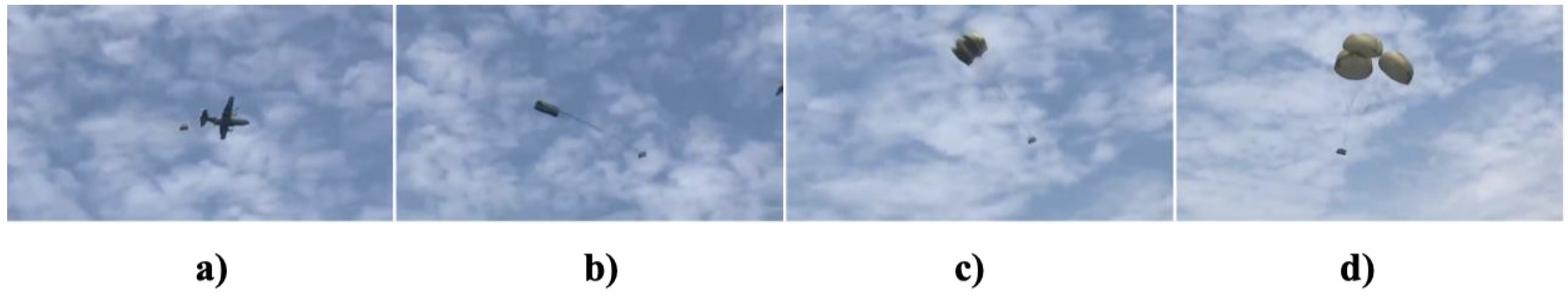
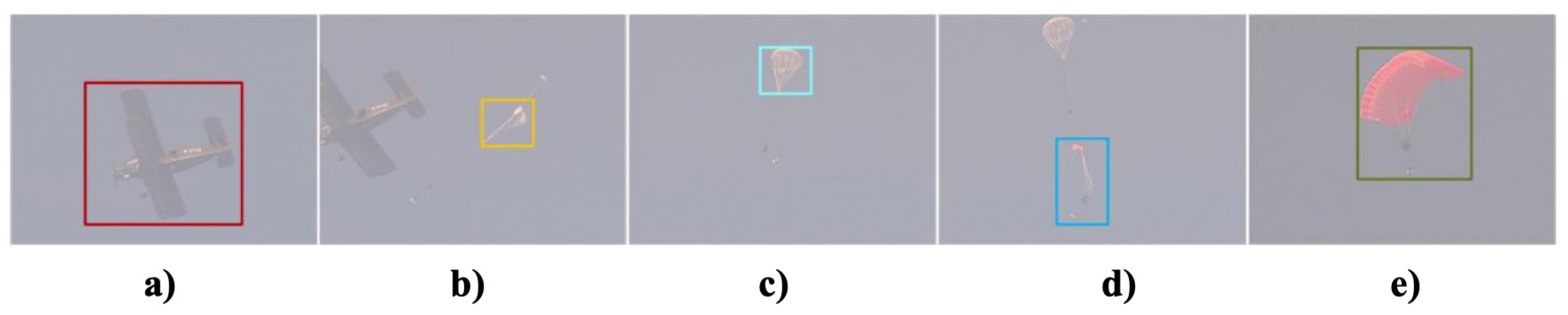
When a large transport aircraft is airdropped, after the fighters or materials are separated from the airframe, the parachute generally has four stages, from opening the parachute bag to fully opening the parachute and then falling smoothly: the free fall phase from leaving the transport aircraft to opening the parachute bag (Figure 1a); from the parachute, pulling the parachute out of the bag to the straightening stage of the parachute and the parachute line (Figure 1b); pulling the parachute and the parachute line until the parachute is inflated (Figure 1c); the parachute is full of air to the steady landing stage of stable descent (Figure 1d). Regarding an airdrop involving heavy equipment such as tanks and infantry fighting vehicles, a pilot chute is usually added to guide the main chute to open. Research shows that airdrop failures often occur during the first three stages [2]. Therefore, if the attitude changes of the parachute in these three stages can be obtained, it will play an important role in the later design and improvement of the parachute. In the fourth stage of the airdrop, if the flight trajectory of the parachute can be accurately obtained, it can provide an effective reference for the design of the fixed-point airdrop program.
Regarding the above problems, more scholars are focusing on how to efficiently and accurately obtain parachute deformation data and trajectory data. At present, the actual data collection mainly involves experimenters holding high-definition high-speed cameras to track and shoot a parachute to obtain the image sequences of the parachute during the entire airdrop process. These images save detailed information such as parachute attitude, which can be used for subsequent research and analysis. However, manual shooting has many disadvantages [3,4]. First, the trajectory of parachutes cannot be obtained. Second, when the parachute leaves the plane, it is a free fall motion and the speed of descent is very fast. For inexperienced photographers, they will often lose the target. Third, shooting for a long time requires a lot of physical strength, resulting in instability during shooting. Then the quality of the shooting picture is significantly reduced; in severe cases, the target will be lost.
In 2004, Mao et al. developed the parachute drop test system, which mainly collects the parachute data by means of photoelectric tracking and records the real landing images for subsequent research [5]. Liu et al. proposed a parachute measurement method based on the Kalman filter. This method is carried out in semi-physical simulations and airdrop experiments; the parachute motion parameters are measured at the same time [6]. The system can track multiple targets simultaneously, with high reliability of airborne equipment and resistance to shock. Zhu and Xiong applied GPS to the parachute airdrop test, mainly using global positioning system (GPS) positioning principles, the spatial distributions of satellites, and the distances between satellites and ground points to rendezvous the ground point location method. The distance of the test point relative to the satellite is continuously and synchronously measured to calculate the space position of the parachute target, and then the flight trajectory of the parachute is obtained [7,8]. Gordon Strickert et al. from the German Space Center installed a camera on a aircraft to record the relative motion of the parafoil and the aircraft, and then calculated the flight attitude of the parafoil using digital image technology according to the recorded relative motion information [9]. Yakimenko and Berlind designed an automatic tracking system that tracked the position and flight attitude of parachutes and dropped objects during an airdrop [10]. In summary, parachute tracking has received a significant amount of attention from various countries. After years of continuous exploration, researchers have proposed and implemented a variety of tracking methods. Each tracking method has different advantages and disadvantages, but in general, the degrees of automation of these tracking methods are generally not high, and the system is not intelligent enough. In the tracking process, experimenters are required to participate throughout the whole process, and there is still a certain distance from the actual artificial intelligence.
Therefore, in this paper, we mainly utilized the computer vision method to track the aircraft and parachutes automatically. Specifically, we designed an turntable servo system; its movement was controlled by means of machine learning algorithms to track the aircraft and parachutes. In addition, we also propose an effective multi-target tracking switch algorithm based on the image frame difference and optical flow, realizing real-time switching from the aircraft to the parachutes in the airdrop tests.
Our main contributions are as follows:
- We propose an turntable servo system named TuSeSy, which can track the aircraft and parachutes in airdrop tests automatically. TuSeSy calculates the differences between the taken images by cameras and the inferred images by tracking algorithms, and then generates the control commands to track the aircraft and parachutes.
- To achieve real-time switching from the aircraft to the parachutes in the airdrop tests, we designed an effective multi-target tracking switch algorithm based on the image frame difference and optical flow.
- We conducted extensive experiments; the results show that TuSeSy cannot only solve the problem of wrong target tracking, but also reduce computational overhead. Moreover, the multi-target tracking switch algorithm has higher computing efficiency and reliability, ensuring the practical applications of the turntable servo system.
The rest of this paper is organized as follows. Section 2 presents a review of the related works. We present the mechanical structure, the architecture, and the hardware parameters of the turntable servo system in Section 3. The main tracking algorithm is presented in Section 4. The performance evaluation of TuSeSy is presented in Section 5. Finally, the conclusion is presented in Section 6.
2. Related Works
Many countries are interested in aircraft and parachute tracking. After years of continuous exploration, researchers have proposed and implemented various tracking methods. With improvements in computer performance, computer vision is attracting more attention and computer visual tracking technology has become one of the most popular research topics. Despite the impressive performance of convolutional neural networks (CNNs) [11], traditional tracking algorithms have irreplaceable positions in scenes with high real-time requirements and no training sets. Due to the high flying speed of an aircraft and the high speed of a parachute from its ejection to its opening, the pilot chute will soon fly out of the view of the camera if the tracking target is not switched from plane to chute in time. The camera is fixed on the turntable. As the turntable rotates, the camera also rotates, which means that the target is tracked in the dynamic background. In order to enable the turntable to follow the aircraft and parachute targets, a tracking algorithm is required to detect the foreground target rapidly under the dynamic background. Hence, a tracking algorithm with a good real-time performance is needed to satisfy the requirement. Background subtraction [12] and frame difference [13] are commonly used to detect a moving target. These methods segment static background information and move foreground objects from the frame sequence.
Background subtraction involves obtaining the moving target; the background image is subtracted from the current frame in the video sequence. It shoots a fixed scene with a static camera [14]. However, the actual background could change, e.g., changes in illumination and shaking of the camera, which will interfere in the detection of moving targets [15]. In recent years, scholars have conducted a lot of research on the background models; many methods were introduced to solve the above-mentioned problems. Evaluations and comparisons for 29 background difference methods can be found in the research [12], e.g., weighted moving mean [16], adaptive background learning [17], Gaussian mixture model (GMM) [18], etc. However, these methods require a lot of calculation times or the detection effects are not very good.
The frame difference involves calculating the difference of two adjacent frames in a video sequence with the moving target in the foreground [13]. However, two obvious disadvantages exist in these methods based on the frame difference. On the one hand, the speed of the frame and the moving target are quite big. On the other hand, the detected foreground targets have aperture and ghosting [19]. However, the aperture and ghosting have little influence on tracking the switched target. For the aperture, what we need is the outline of the foreground but not the full foreground [20]. For the ghosting, the camera is mounted on a turntable; the turntable keeps the target in the center of the field of view without causing a greater displacement of the target in the field of view, which thereby effectively curbs the ghosting phenomenon [21]. Regarding a relatively simple background, frame differences can obtain good detection results, have good performances in computing power, and are not sensitive to light intensity changes [22]. The paper is mainly based on the detection of aircraft and parachutes with quite simple backgrounds, such as the sky. As the camera is mounted on the turntable and rotates with the turntable, we can obtain a sky background from different angles; the light intensity of the background also changes rapidly with the rotation. In order to enable the turntable to track the target in real time, the motion detection algorithm needs to have a better real-time performance. The frame difference has good performance in terms of light sensitivity and real-time requirements. Therefore, the frame difference method is used as the target detection algorithm for the motion foreground.
Optical flow is one of the most widely used tracking algorithms for computer vision [23]. The optical flow field provides accurate information about the moving target and can convert low-level flow data to higher-level computer vision tasks [24,25,26]; this means it has better performance in computing power. Optical flow has excellent performance in tracking accuracy and is widely used in a variety of visual tracking tasks [27]. Senst et al. [28] proposed an adapting tracking window optical flow algorithm that can enhance the robustness of the algorithm by automatically adjusting the tracking window size as the target deforms; it also has a high tracking speed. Regarding the aircraft and parachute tracking problem, the size of the parachute changes rapidly when it executes the process of ’thrown out’ and completely opened up. Hence, adapting the window sizes of optical flow can solve the tracking problem. Therefore, this paper designed a target tracking algorithm according to the optical flow tracking approach.
3. Case Study
In order to track the aircraft and parachutes automatically, we designed an turntable servo system named TuSeSy, which consists of cameras and a two-degree-of-freedom turntable. In this section, we introduce the mechanical structure, the architecture, and the hardware parameters of the turntable servo system.
3.1. Mechanical Structure of TuSeSy
The basic principle of motion control in TuSeSy is that when the image processing algorithm gives the position deviation signal of the target, TuSeSy drives the camera to the tracked target according to the position deviation signal. The load, speed, acceleration, and tracking accuracy are considered in the design of TuSeSy. The design goal was to ensure that the turntable servo system could still achieve accurate tracking under large speed conditions and acceleration.
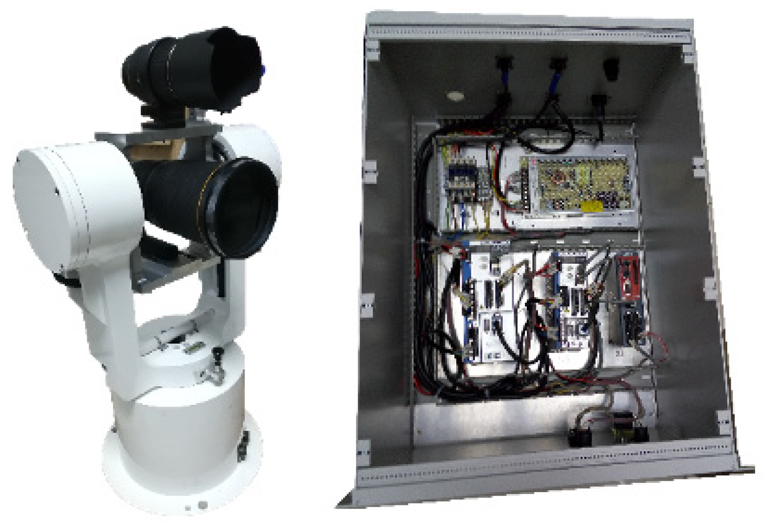
Through the analysis of TuSeSy’s technical requirements, the structure of the turntable is an azimuth-pitch type. Figure 2 shows the material objects of the turntable; the driving side is a coaxial direct drive motor. Coaxial direct drive has the following advantages. First, it can effectively avoid the gap error caused by the reducer and gear transmission. Second, it has a high precision and high dynamic response while ensuring accuracy. Therefore, the coaxial direct motor drive structure is suitable for the high precision and dynamic response of a turntable scene. The turntable is made of aluminum alloy, which is produced by casting. Aluminum alloy not only has high strength and low density, but it can effectively reduce the overall mass of the turntable while ensuring its strength.
3.2. Architecture of TuSeSy
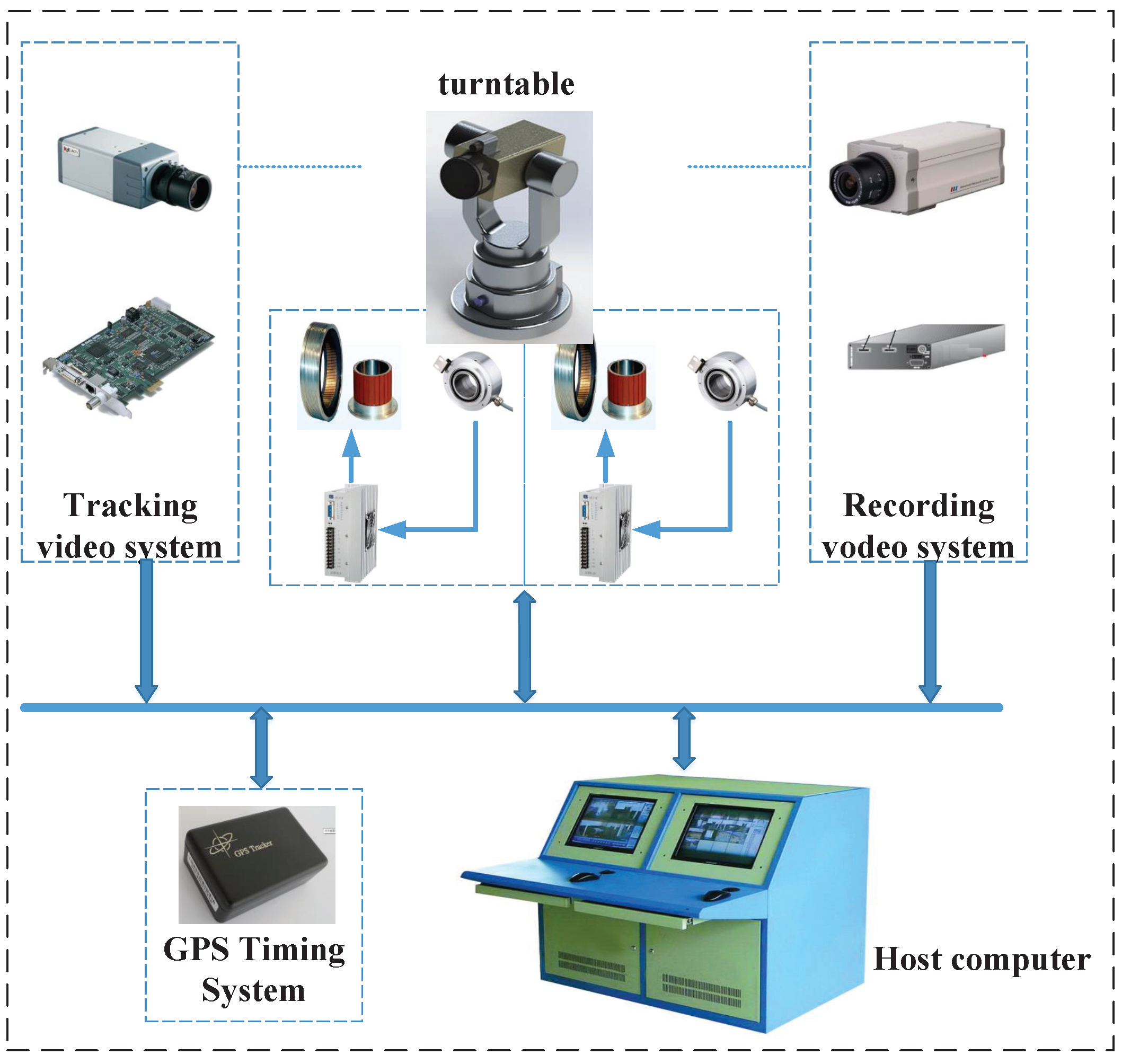
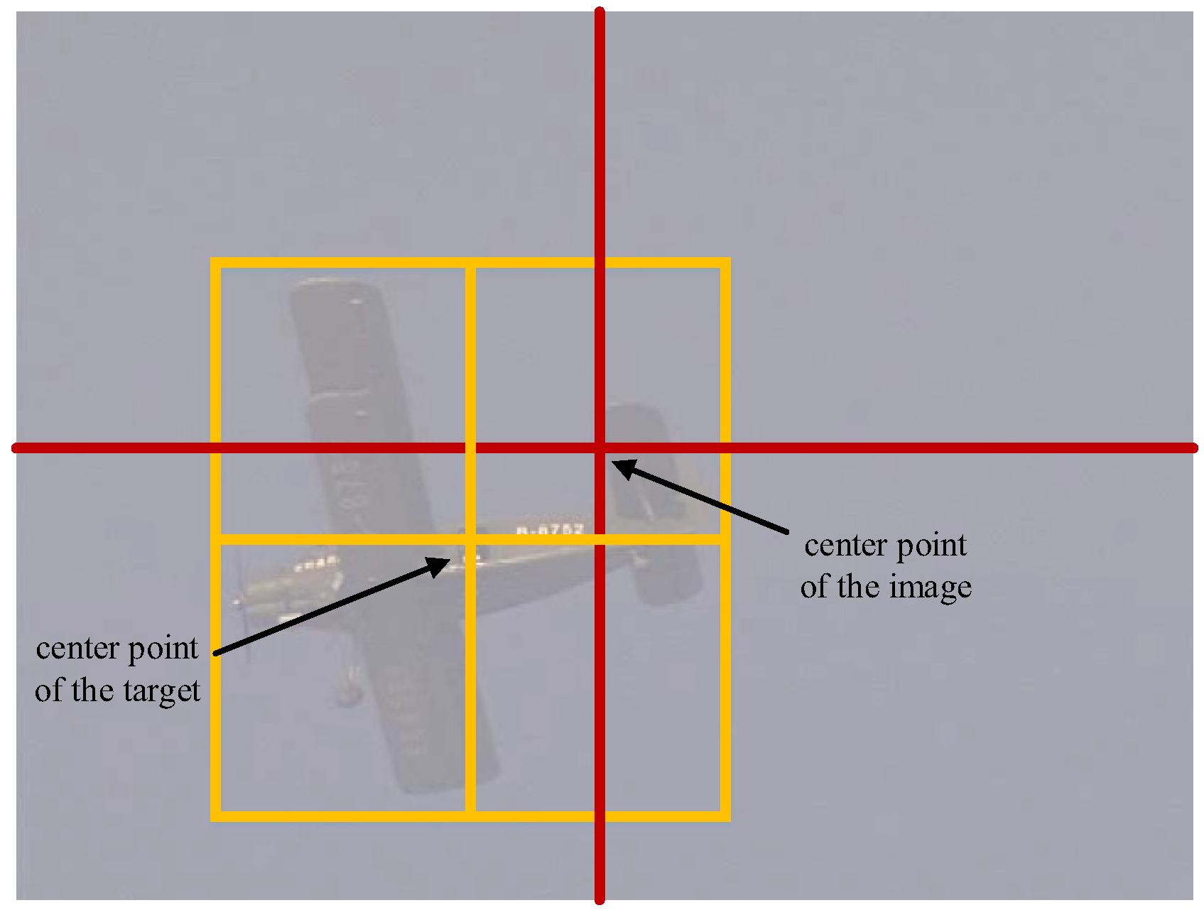
After the design of the turntable is completed, a servo system is needed to realize accurate control of the azimuth and pitch axis of the turntable. We designed a turntable servo system called TuSeSy to track the aircraft and parachutes, as shown in Figure 3. TuSeSy includes a two-degree-of-freedom turntable (azimuth axis, pitching axis) and two cameras (one is for tracking and the other—with high-speed—is for recording). The azimuth angle and the pitching angle of the turntable correspond to the azimuth axis and pitching axis, respectively. The tracking camera uploads the images containing targets to the host computer. Based on the uploaded images, the host computer adopts the tracking algorithm to calculate the position of the target in the image, and then the difference between the center of the current frame and that of the target is obtained, as shown in Figure 4. Finally, the turntable uses the difference to generate control signals to operate the yaw angle and pitch angle of the turntable for achieving real-time tracking. The recording camera is applied to shoot the parachute and record its flight attitude.
3.3. Hardware Parameters of TuSeSy
The key hardware parameters selected for TuSeSy are as follows:
- 1.
- The model of the tracking camera: PointGray (GS3-U3-41C6C-C), resolution: 2048 × 2048, pixel size: 5.5 m;
- 2.
- The model of the tracking camera lens: AF-Smicro NIKKOR 105 MM1:2.8 g, focal length: 50 mm;
- 3.
- The model of the high-speed recording camera: IO industries (Flare 2M360CCL), frame speed: up to 375FPS, resolution: 1088 × 2088;
- 4.
- The model of the high-speed recording camera lens: VR 500/4G;
- 5.
- The model of the Kr Morgan motor used for azimuth axis: KBMS-25H01-A00; the model of the corresponding driver: AKD-P01206-NBEC-0000;
- 6.
- The model of the Kr morgan motor used for the pitching axis: KBMS-17H01-A00; the model of the corresponding driver: AKD-P00606-NBEC-0000.
- 7.
- The multi-axis controller: Pyeon, model: Beckhoff (CX5130-0125);
- 8.
- The image workstation (CPU: Intel 7700 K, memory: 32 GB, graphics card: GV-N1080Ti, operating system: Linux).
4. The Design of the Tracking Algorithm
4.1. Introduction of the Multi-Target Tracking Switch
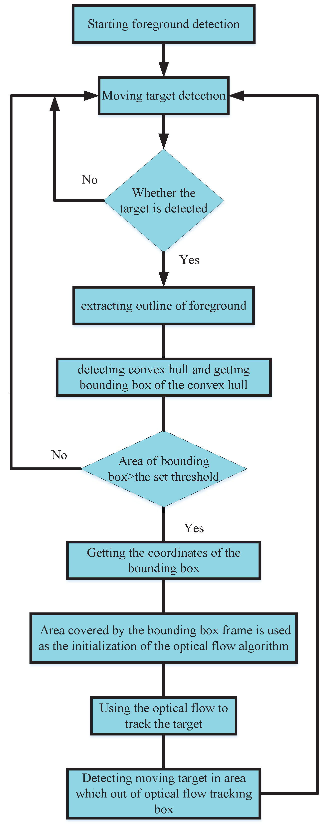
In recent years, many scholars have studied the problems of tracking multiple targets [29,30,31,32]. The research mainly involved solving the challenges of tracking failures caused by the existence of obstructions among multiple targets or the cross motions among similar targets. Most multi-target tracking studies involve relatively static backgrounds. Few research studies have focused on a multi-target tracking switch problem under a dynamic background. The main purpose of this paper was to design an intelligent turntable servo system that automatically tracks airdrops and parachutes and acquires their flight paths and attitudes. The specific tracking process is shown in Figure 5.
- When the aircraft enters the camera’s field of view, TuSeSy automatically captures the aircraft’s target by target measurement and then tracks the aircraft using a tracking algorithm, as shown in Figure 5a.
- The system controls the turntable rotation according to the camera return deviation signal, so that the camera is aimed at the target under test. After a period of flight, the aircraft begins an airdrop mission, throwing objects from the aircraft and opening the pilot chute, as shown in Figure 5b.
- It is necessary to make TuSeSy automatically detect the pilot chute, and decide whether to abandon the aircraft’s tracking and start tracking the pilot chute instead (Figure 5c).
Throughout the tracking process, the tracking tasks of TuSeSy can be divided into three parts: tracking the aircraft, tracking the pilot chute, and tracking the main chute. It is obvious that TuSeSy needs to track multiple targets—unlike the existing multi-target tracking algorithm that tracks multiple targets in the image at the same time. TuSeSy needs one switch after another to track the targets that appear in turn during the airdrop. The algorithm flow chart is shown in Figure 6.
4.2. Trajectory Acquisition
As a single turntable cannot calculate the depth of the aircraft and parachutes in space, it is unable to obtain the three-dimensional trajectory of the flight. To deal with this problem, TuSeSy adopts two turntables to position the target, which contributes toward calculating the depth of the target in space.
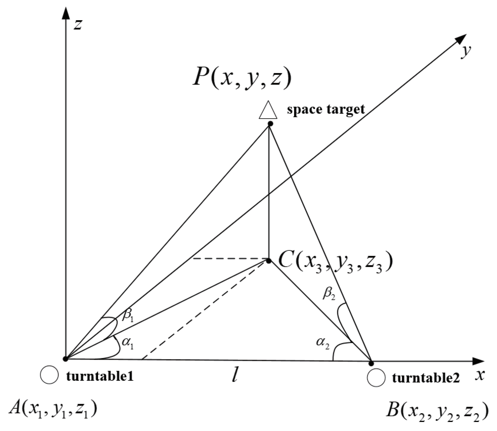
Two tracking turntables were previously placed on the positions where two principal optic axes of the cameras intersected at the point where the target was. We obtained the distance l between the two turntables by GPS. In addition, the elevation angles (, ) and the azimuth angles (, ) could also be accessed from the turntables, respectively. Based on these five parameters, the target’s spatial coordinates could easily be calculated with the following equations:
The elevation angle is used to verify whether the measurement error e is within an acceptable range.
According to Equations (1)–(3), a series of three-dimensional coordinate values of targets could be obtained, and then the coordinate values of outlier points with large errors could be eliminated based on Equations (4) and (5). As a result, the remaining coordinates could be used for curve fitting by the least squares method to calculate the space trajectory of the target. The target’s trajectory measurement principle is shown in Figure 7.
4.3. Moving Target Capture in a Dynamic Background
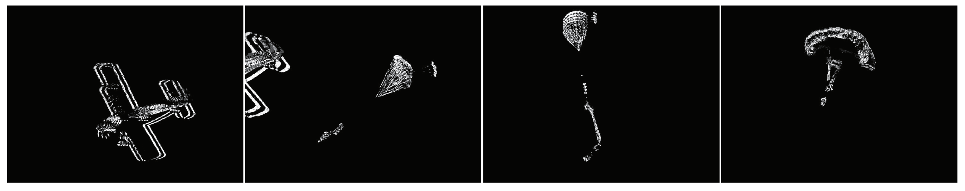
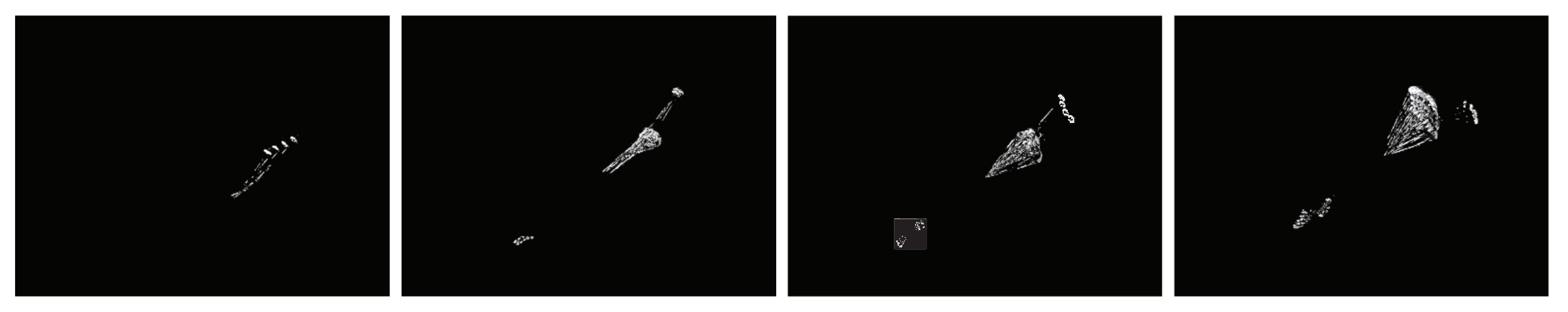
Foreground Segmentation. When abnormal object movement occurs in the monitoring scene, there will be an obvious difference between frames. When two frames are subtracted, the absolute value of the brightness difference between two frames is obtained; whether it is greater than the threshold, it is judged to analyze the motion characteristics of the image sequence and determine whether there is object movement in the image sequence. Let be the and frame in the frame sequence. The frame difference involves subtracting the adjacent two frames; that is, . The obtained differential image is represented as DFrame, and the image acquired by the camera is srcImage. The experimental results are shown in Figure 8. The algorithm is shown in Algorithm 1.
| Algorithm 1: Foreground segmentation by frame difference |
| Input: capture the adjacent two frames from the camera: Output: foreground:
|
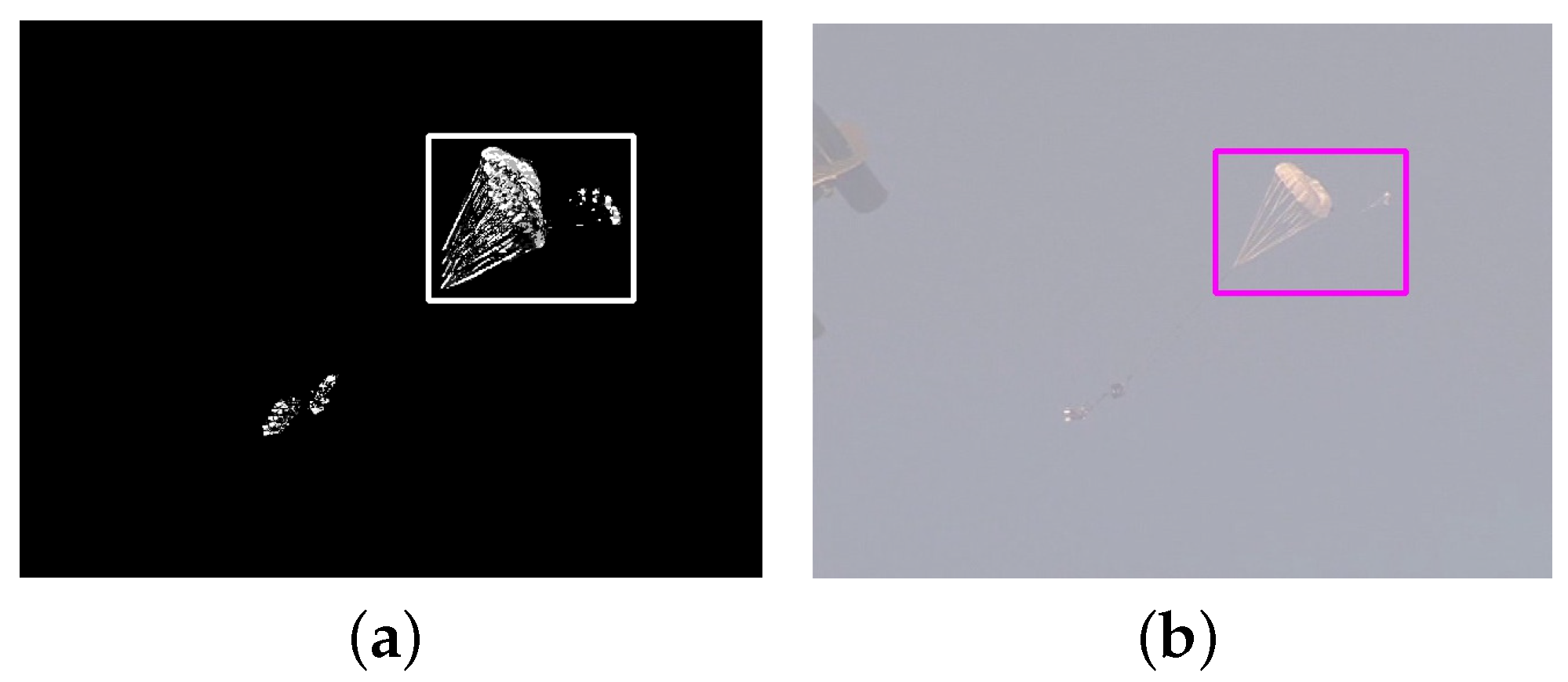
Target Positioning. The foreground segmentation obtained by the frame difference method shows that the detected moving objects have smaller ghosting and aperture. However, these defects will not affect the final bounding box. After the foreground segmentation, only the outline of the target was extracted. The moving object detection technique takes place in a field environment, so some interference contours will be detected when the light interference is relatively large. We only selected the contours with the largest area so that the interference contours could be filtered out. After the maximum contour was obtained, the convex hull was detected, and then the bounding box of the convex hull was captured. The bounding box framed the foreground. The target capture results and the specific algorithm are shown in Figure 9 and Algorithm 2, respectively.
| Algorithm 2: Positioning the captured foreground target. |
| Input: foreground: DFrame Output: area of the bounding box of the foreground
|
4.4. Tracking Switch Algorithms
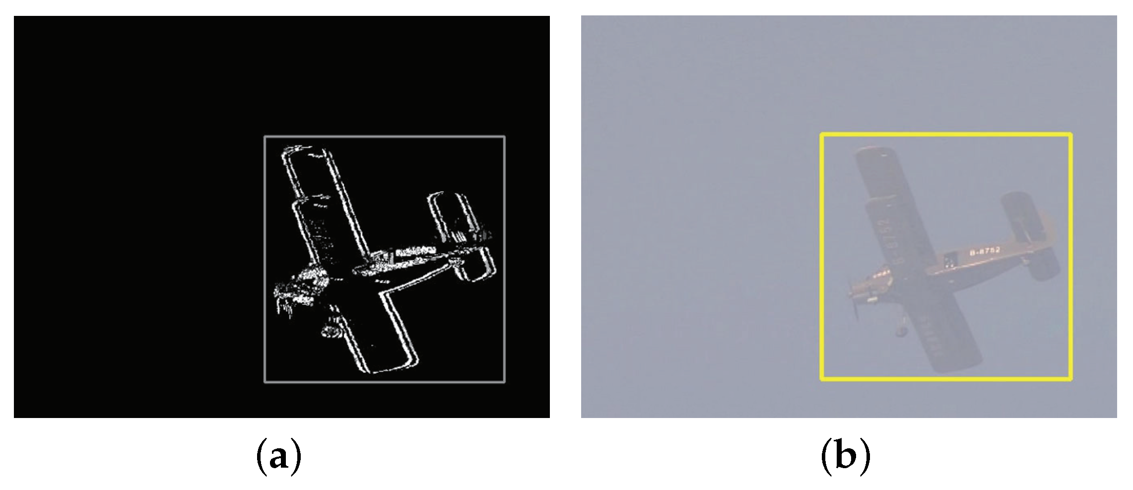
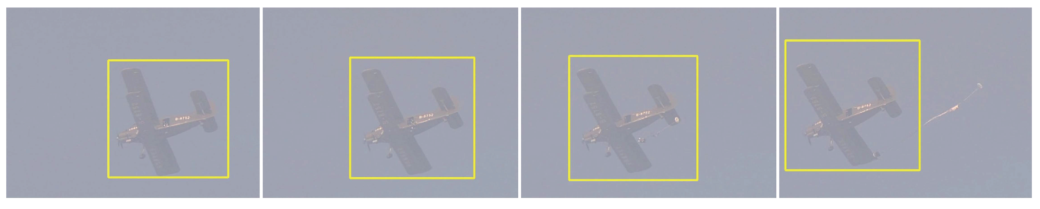
Tracking the Aircraft. When TuSeSy is started, the frame difference starts to detect moving objects and the frame difference detects the aircraft. First, a box covering the target could be obtained using the method of positioning the captured foreground target, as shown in Figure 10a. The coordinates and size of the box are transferred to the corresponding original image, as demonstrated in Figure 10b. Then, the area covered by the box in the original image is taken as the initialization of optical flow for tracking target characteristics. Finally, the optical flow is utilized to track the target continuously, as depicted in Figure 11. The specific aircraft tracking process is shown in Algorithm 3.
| Algorithm 3: Capture and track the aircraft. |
|
start timer: 30 ms recall Algorithm 1 recall Algorithm 2 if Area of the bounding box > the set threshold do init of optical flow: flowtracker.init(srcImage, box) the optical flow to track the aircraft target: flowtracker.update (srcImage, box) for each detected box do calculate the aircraft of each srcImage: flowtracker.update(srcImage[i + 1], box) obtain the coordinates and sizes of the bounding box: box.tl(),box.br() return box.tl(),box.br() end for |
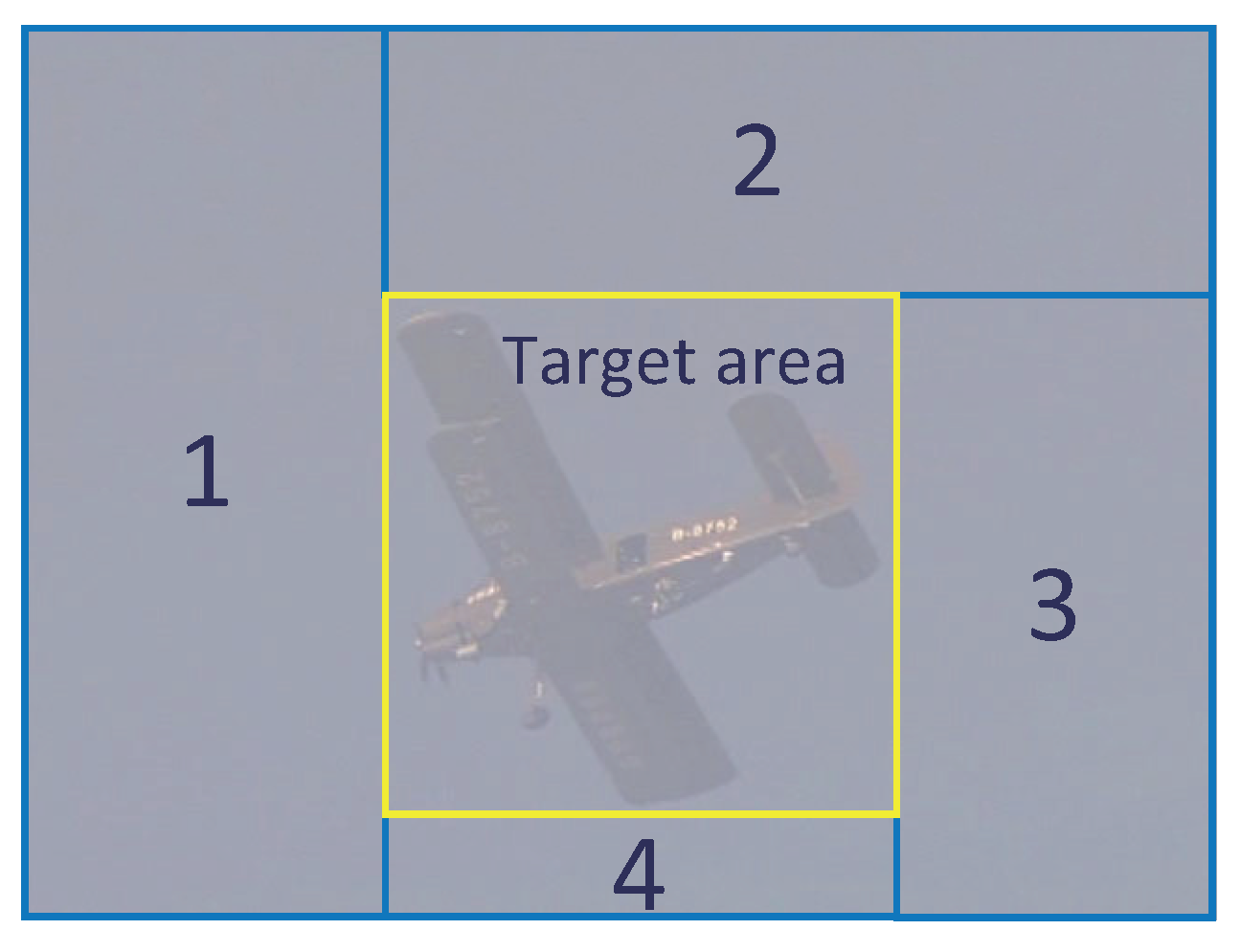
Tracking from the Aircraft to the Pilot Chute. When tracking the aircraft using the optical flow, it takes the tracking box as the center and divides the image into five blocks, as shown in Figure 12. Before the pilot chute is thrown, the aircraft is tracked by the optical flow. At the same time, the moving target that is out of the aircraft tracking box is detected by the frame difference. That is to say, the movements of areas 1,2,3,4 shown in Figure 12 are detected so that the aircraft is not detected again, and it can avoid the interference of the aircraft when detecting the pilot chute. To improve the speed of the algorithm, the area of the pilot chute can be predicted according to the direction of the flight.
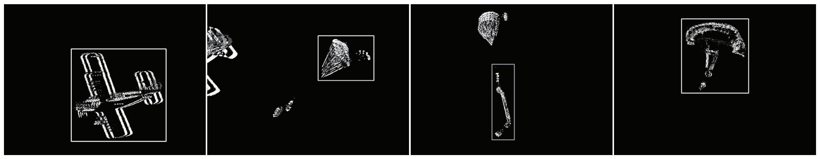
Figure 13a,b demonstrate that when the plane enters the camera field from left to right, the thrown pilot chute will appear at the bottom left of the image, which is shown in area 1.4 of Figure 12. In contrast, when the plane enters the camera field from right to left, the parachute will appear at the bottom right of the image, which is shown in area 3.4 of Figure 12. Therefore, according to the flight direction of the aircraft, the target is searched for in the predicted region to reduce the data that need to be processed and improve the speed of the algorithm.
Since the frame difference detects moving targets in the predicted area all of the time, once the pilot chute is thrown, it will be detected immediately, as shown in Figure 14. From the pilot chute being thrown to opening, the detected area greatly changes. When the detected area of the pilot chute is greater than the set threshold (the threshold is 48.4 times larger than the first detected area of the parachute), the pilot chute is positioned with the proposed method of positioning the captured foreground target, as shown in Figure 15a. The coordinates and sizes of the current bounding box are transferred to the current original image. In addition, the area covered by the box frame in the original image is used as the initialization of the optical flow to track the target features. Therefore, the switching of the tracking target from the aircraft to the pilot parachute is realized, and the optical flow is used to track the new target (pilot chute), as shown in Algorithm 4.
| Algorithm 4: Tracking from the aircraft to the pilot chute. |
|
continue to Algorithm 3 determine the direction of the aircraft detect the pilot chute in the predicted area: Algorithm 1 if find contours do Algorithm 2 if Area of bounding box > the set threshold do init of optical flow: flowtracker.init(srcImage[i], box) for each detected box do calculate the aircraft of each srcImage: flowtracker.update(srcImage[i + 1], box) obtain the coordinates and sizes of the bounding box: box.tl(),box.br() return box.tl(),box.br() end for |
Tracking from the Pilot Chute to the Main Chute. The pilot chute throws the main chute; the main chute appears below the pilot chute. The tracking switch from the pilot chute to the main chute is similar to that from the aircraft to the point chute. Therefore, the area below the pilot chute; that is, area 4, needs to be detected. The detailed process is shown in Algorithm 5.
| Algorithm 5: Tracking from the pilot chute to the main chute. |
|
continue to Algorithm 4 detect the main chute in the predicted area: Algorithm 1 if find contours do Algorithm 2 if Area of the bounding box > the set threshold do init of the optical flow: flowtracker.init (srcImage, box) for each detected box do calculate the aircraft of each srcImage: flowtracker.update(srcImage[i + 1], box) obtain the coordinates and sizes of the bounding box: box.tl(),box.br() return box.tl(),box.br() end for |
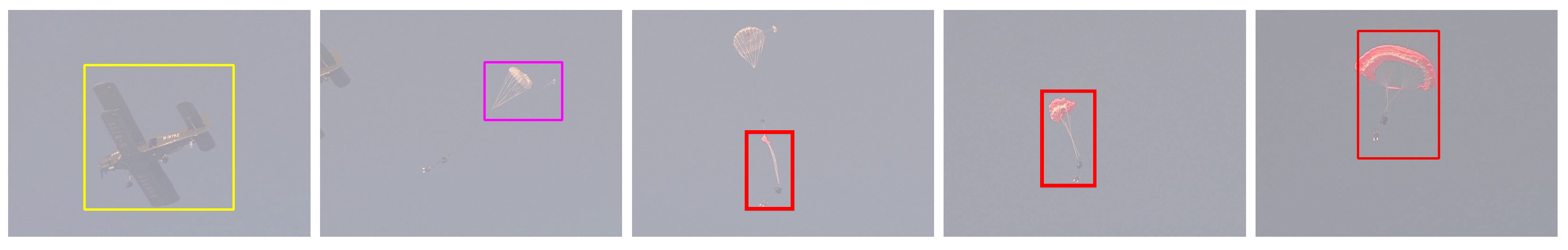
Through the proposed multi-target switching–tracking algorithm, we successfully solved the multi-target tracking switch problem from the aircraft to the parachute in the airdrop test; however, the system has certain versatility limitations, as shown in Figure 16.
5. Experiment
To evaluate the performance of TuSeSy, we conducted extensive experiments that included an actual real airdrop test and simulation. Specifically, we first captured the frame sequences of two actual airdrop videos and two simulated videos by UAV. Then we focused on the influence of the rapid change of light intensity on the frame difference and the background subtraction when they segmented the foreground from the background (referring to the sky). Finally, we conducted several experiments to verify the feasibility and reliability of the multiple tracking switch algorithm proposed in TuSeSy. Details of the selected videos are as follows:
- Video1: the airplane went into the view field from the right (640 × 480 × 400 frames);
- Video2: the airplane went into the view field from the left (640 × 480 × 800 frames);
- Video3: the UAV simulated with the clouds as background (640 × 480 × 300 frames);
- Video4: the UAV simulated with the birds as a distraction.
5.1. Evaluation Methodology
For the turntable to track the target, we used the difference between the target center point and the image center point as a control signal to control the azimuth and yaw angle of the turntable. Therefore, the bounding box region of the target in each frame was used as the relevant area, and the bounding box of the target was selected as the detected area in the foreground frame. In this paper, we mainly evaluated the performance of TuSeSy from the following metrics. In the following evaluation, we used the F2-score and FPS as our major metrics to evaluate the detection accuracy.
- Accuracy: the percentage of samples with correct detection in the total samples.
- Precision: the percentage of samples that were correctly detected as A in all samples detected as A.
- Recall: the percentage of samples that were detected as A in the samples truly belonged to A.
- F2-score: a metric that combined precision (P) and recall (R) (). We set to increase the weight of the recall, i.e., reducing the missing report rate of the wrong detection, ensuring precision.
- FPS: the speed of the algorithm with frame per second.
5.2. Impact of Frame Difference and Background Subtraction
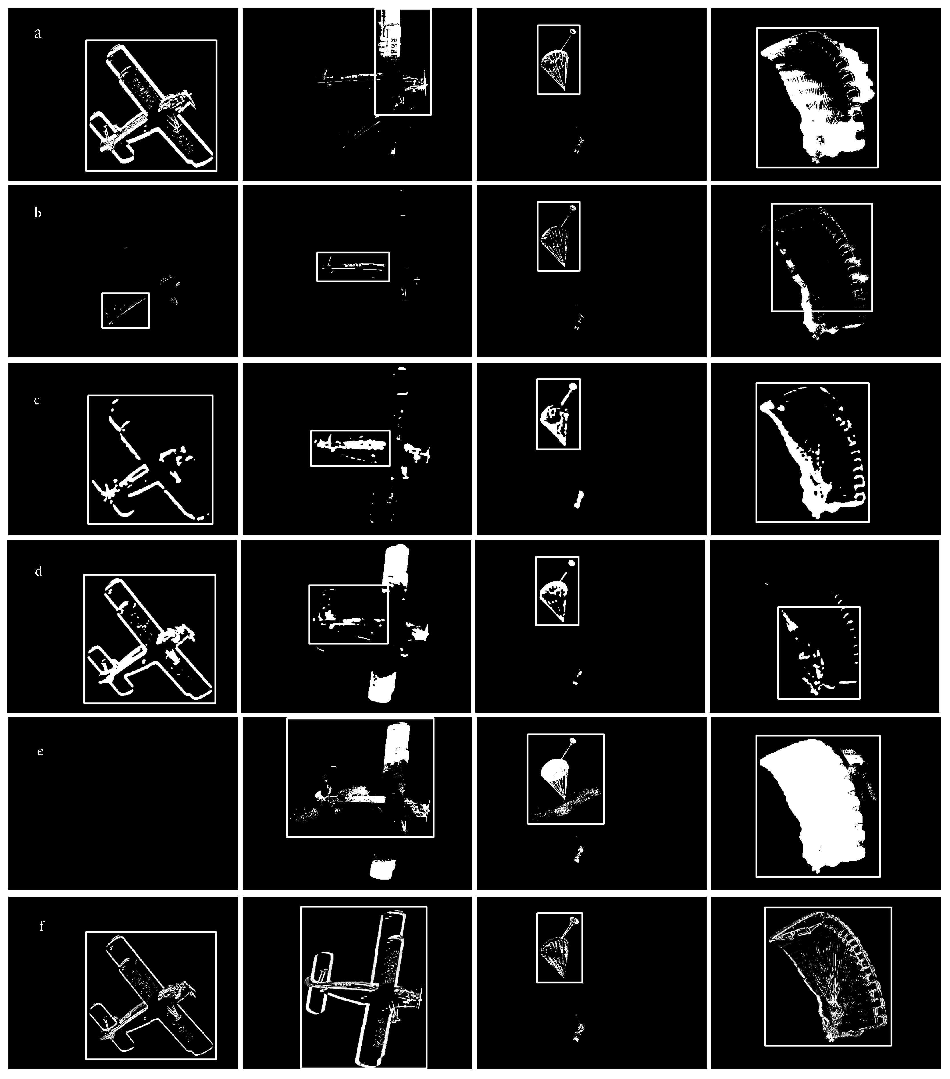
According to reference [11], which presents 29 kinds of background subsections, we selected 5 outstanding algorithms—DPWrenGABGS, MixtureOfGuassianV1BGS, MultiLayerBGS, PixelBasedAdaptiveSegmenter, and LBAdaptiveSOM—to present a contrast experiment with general frame differences when segmenting the foreground (aircraft and parachutes) from the background (the sky). Each video had the same threshold, which was used to maximize the F2-score. We utilized the semi-automatic calibration method to obtain the F2-score. Table 1 and Table 2 show the average of the F2-score and FPS from all frames in each video.
Figure 17a–e presents the foreground segmented from video2 using DPWrenGABGS, MixtureOfGuassianV1BGS, MultiLayerBGS, PixelBasedAdaptiveSegmenter, and LBAdaptiveSOM, respectively. Figure 17f is the foreground segmented from video2 with the general frame difference method. Figure 17a–d demonstrate that DPWrenGABGS, MultiLayerBGS, and PixelBasedAdaptiveSegmenter can segment the foreground of the plane perfectly; however, with the turntable rotating continuously, the light intensity of the background changes constantly (rapidly weakens); the update of the background may be delayed ( frame). Figure 17b shows that MixtureOfGuassianV1BGS cannot entirely segment the foreground.
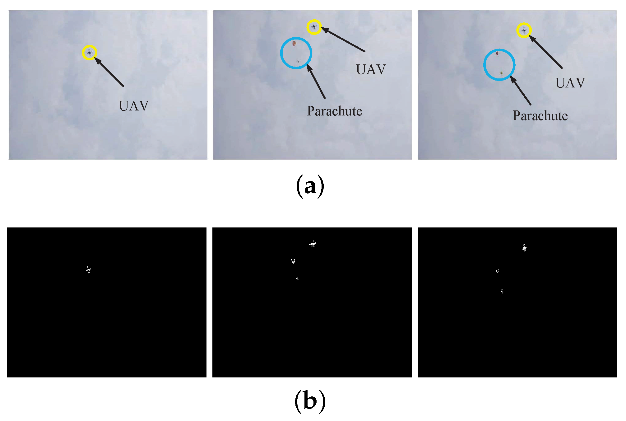
Figure 17e implies that although LBAdaptiveSOM uses the first 52 frames as learning sets, in the following segment, there are still existing problems, e.g., the foreground is incomplete or inaccurate and the bounding box cannot frame the target completely or correctly. As for Figure 17f, we can conclude that the general frame difference can segment the foreground well in each frame with good adaptive capacity to the change of the light intensity. Since the control signal of the turntable can make the tracking target as far as possible in the center of each frame, the target in each frame will not experience serious ghosting. In addition, the bounding box can fit the target border well. Furthermore, Table 1 and Table 2 also show that the general frame difference has the largest F2-score and highest FPS. MultiLayerBGS has a relatively high F2-score in contrast to other background differences; however, it has the lowest FPS. The foregrounds from video1 and video4 are similar to video2. Video3 segmented the foreground well with the background of clouds, using the general frame difference, which has a good F2-score and a high FPS (Figure 18).
5.3. Impact of Target Tracking Switch Algorithm
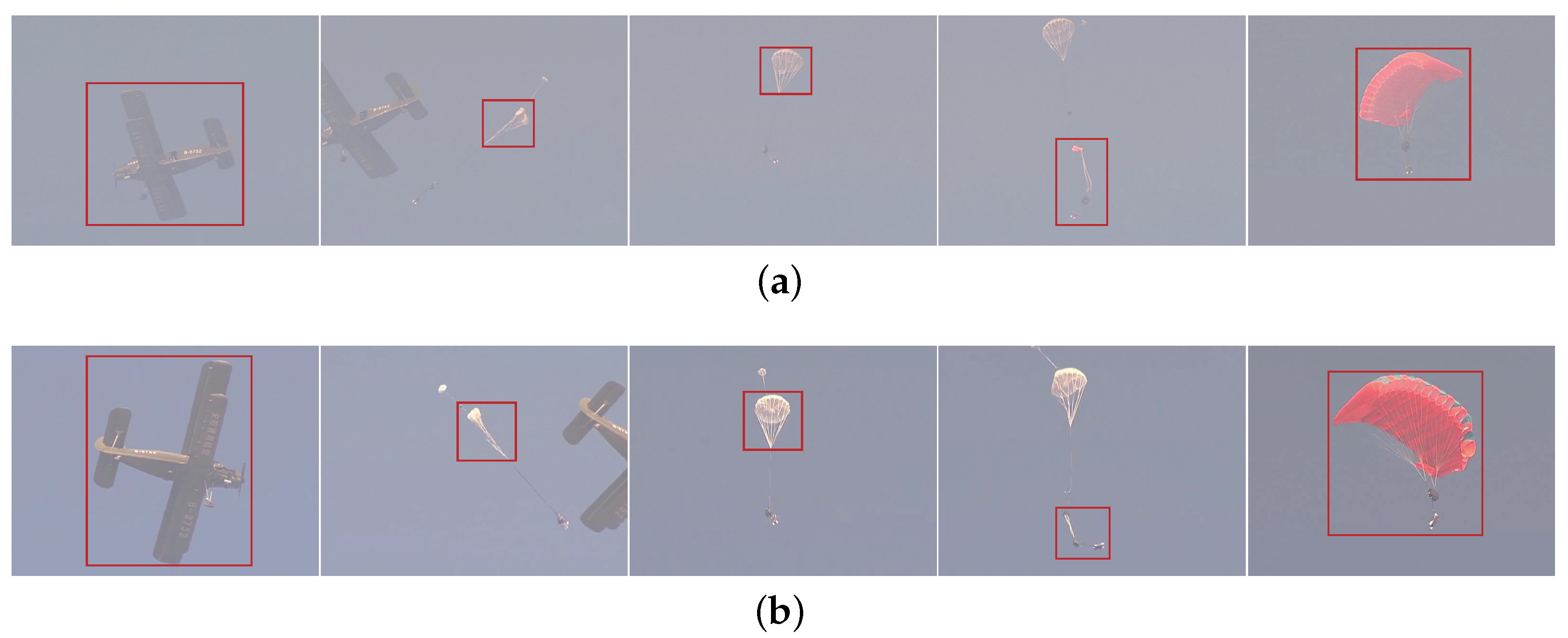
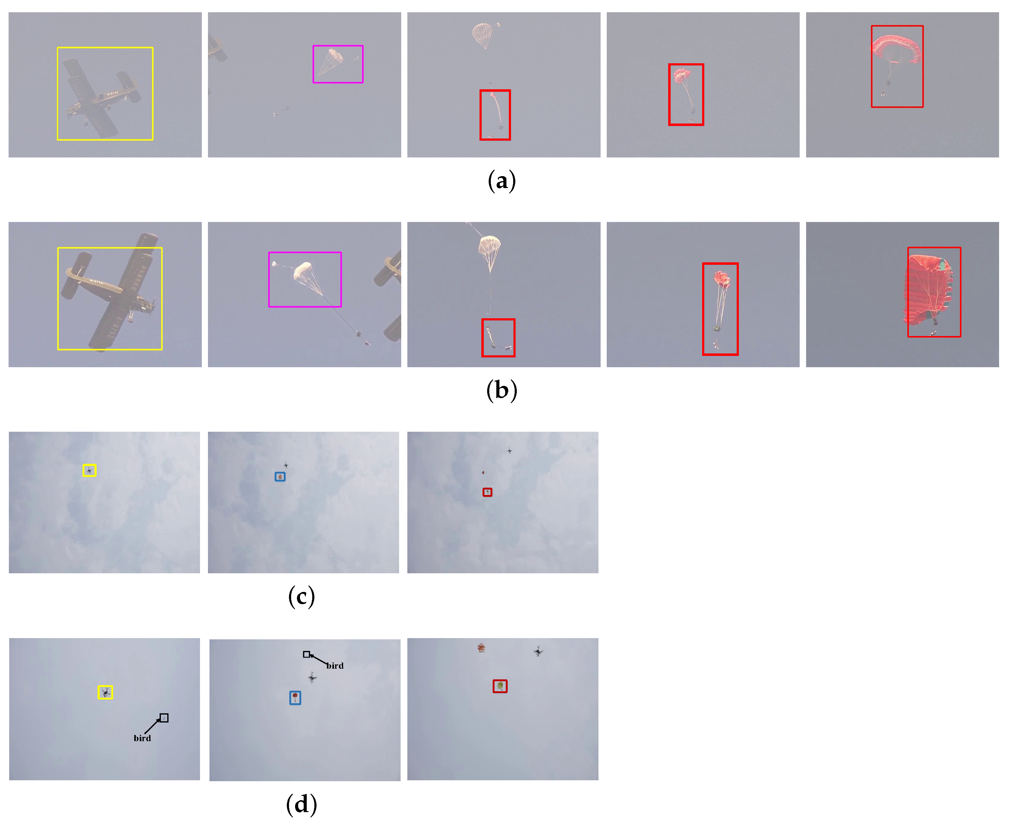
From Table 3, we see that the target tracking switch algorithm has good tracking accuracy, with an F2-score up to 0.8. The multi-target tracking switch algorithm processing speed reached more than 40 FPS and the amount of recorded data satisfied the requirements of the drawing trajectory. The third, fourth, and fifth frames in Figure 19a,b show that the window sizes of the optical flow were well adapted to the deformation of the parachute. In addition, the feasibility of the partition search parachute goal was proved and achieved. Figure 19c shows that the algorithm in the cloudy weather still has good tracking results; the algorithm adapts to the light and the weather well. When there was a bird in the frame in Figure 19d, the algorithm captured the plane and the parachute efficiently (it was not disturbed by the bird). The reason is that we chose the largest bounding box instead of other smaller boxes caused by the distraction, the result of the tracking shows that the algorithms we proposed have strong reliability.
6. Conclusions
In this paper, we designed an intelligent turntable servo system called TuSeSy to track aircraft and parachutes automatically in airdrop tests. TuSeSy calculates the differences between the actual taken images and the inferred images to generate the control commands for tracking the target. We also proposed a multi-target tracking switch algorithm based on the image frame difference and optical flow to switch the tracking from the aircraft to the parachute. The extensive experiments demonstrated that TuSeSy not only has a higher FPS and detection accuracy, but it also solves the wrong target tracking problem. In the future, it will be necessary to analyze the collected parachute images to obtain the landing flight attitude parameters, provide a reference for the parachute optimization design, and promote the development of the parachute airdrop platform.
Author Contributions
Conceptualization, Z.Z. and Z.P.; data collection, Z.T.; analysis and interpretation of results, Z.Z. and F.G.; validation, Z.Z. and F.G.; writing—original draft preparation, Z.Z. and F.G.; writing—review and editing, F.G. All authors have read and agreed to the published version of the manuscript.
Funding
This work was supported by the China Postdoctoral Science Foundation (2020M671597), Jiangsu Postdoctoral Research Foundation (2020Z100), the National Science Foundation of the Jiangsu Higher Education Institutions of China (20KJB520002), Suzhou Planning Project of Science and Technology (no. SYG202024), and the Priority Academic Program Development of Jiangsu Higher Education Institutions (PAPD).
Institutional Review Board Statement
Not applicable.
Informed Consent Statement
Not applicable.
Conflicts of Interest
The authors declare no conflict of interest.
References
- Tao, J.; Sun, Q.; Sun, H.; Chen, Z.; Dehmer, M.; Sun, M. Dynamic modeling and trajectory tracking control of parafoil system in wind environments. IEEE/ASME Trans. Mechatron. 2017, 22, 2736–2745. [Google Scholar] [CrossRef]
- Xu, B. Disturbance observer-based dynamic surface control of transport aircraft with continuous heavy cargo airdrop. IEEE Trans. Syst. Man Cybern. Syst. 2016, 47, 161–170. [Google Scholar] [CrossRef]
- Wang, W.; Shen, J.; Porikli, F.; Yang, R. Semi-supervised video object segmentation with super-trajectories. IEEE Trans. Pattern Anal. Mach. Intell. 2018, 41, 985–998. [Google Scholar] [CrossRef] [PubMed]
- Gnemmi, P.; Changey, S.; Wey, P.; Roussel, E.; Rey, C.; Boutayeb, M.; Lozano, R. Flight phases with tests of a projectile-drone hybrid system. IEEE Trans. Control Syst. Technol. 2017, 26, 2091–2105. [Google Scholar] [CrossRef]
- Mao, Q. Development of a parachute airdrop test system. In Measurement and Control Technology; Beihang University Press: Beijing, China, 2004; pp. 72–75. (In Chinese) [Google Scholar]
- Liu, N.; Tian, T.; Su, Z.; Qi, W. Research on Measurement Method of Parachute Scanning Platform Based on MEMS Device. Micromachines 2021, 12, 402. [Google Scholar] [CrossRef]
- Zhu, G. Research on the Testing Algorithm of Parachute Air-Drop Experiment Based on GPS. Master’s Thesis, Huazhong University of Science and Technology, Wuhan, China, 2008. [Google Scholar]
- Xiong, W. Research on the Testing Device of Parachute Air-Drop Experiment Based on GPS. Master’s Thesis, Huazhong University of Science and Technology, Wuhan, China, 2008. [Google Scholar]
- Strickert, G.; Jann, T. Determination of the relative motion between parafoil canopy and load using advanced video-image processing techniques. In Proceedings of the 15th Aerodynamic Decelerator Systems Technology Conference, Toulouse, France, 8–11 June 1999; pp. 410–417. [Google Scholar]
- Yakimenko, O.; Berlind, R.; Albright, C. Status on video data reduction and air delivery payload pose estimation. In Proceedings of the 19th AIAA Aerodynamic Decelerator Systems Technology conference and seminar, Williamsburg, VA, USA, 21–24 May 2007; p. 2552. [Google Scholar]
- Girshick, R.; Donahue, J.; Darrell, T.; Malik, J. Rich feature hierarchies for accurate object detection and semantic segmentation. In Proceedings of the IEEE conference on computer vision and pattern recognition, Columbus, OH, USA, 23–28 June 2014; pp. 580–587. [Google Scholar]
- Sobral, A.; Vacavant, A. A comprehensive review of background subtraction algorithms evaluated with synthetic and real videos. Comput. Vis. Image Underst. 2014, 122, 4–21. [Google Scholar] [CrossRef]
- Zhang, J.; Cao, J.; Mao, B. Moving object detection based on non-parametric methods and frame difference for traceability video analysis. Procedia Comput. Sci. 2016, 91, 995–1000. [Google Scholar] [CrossRef] [Green Version]
- Ramya, P.; Rajeswari, R. A modified frame difference method using correlation coefficient for background subtraction. Procedia Comput. Sci. 2016, 93, 478–485. [Google Scholar] [CrossRef] [Green Version]
- Rashid, M.; Thomas, V. A Background Foreground Competitive Model for Background Subtraction in Dynamic Background. Procedia Technol. 2016, 25, 536–543. [Google Scholar] [CrossRef] [Green Version]
- Zhong, Z.; Wang, A.; Kim, H.; Paynabar, K.; Shi, J. Adaptive Cautious Regularized Run-to-Run Controller for Lithography Process. IEEE Trans. Semicond. Manuf. 2021, 34, 387–397. [Google Scholar] [CrossRef]
- Mandal, M.; Dhar, V.; Mishra, A.; Vipparthi, S.K.; Abdel-Mottaleb, M. 3DCD: Scene independent end-to-end spatiotemporal feature learning framework for change detection in unseen videos. IEEE Trans. Image Process. 2020, 30, 546–558. [Google Scholar] [CrossRef] [PubMed]
- Jin, X.; Wang, Y.; Zhang, H.; Zhong, H.; Liu, L.; Wu, Q.J.; Yang, Y. DM-RIS: Deep multimodel rail inspection system with improved MRF-GMM and CNN. IEEE Trans. Instrum. Meas. 2019, 69, 1051–1065. [Google Scholar] [CrossRef]
- Wu, Y.; Zhu, L.; Wang, X.; Yang, Y.; Wu, F. Learning to anticipate egocentric actions by imagination. IEEE Trans. Image Process. 2020, 30, 1143–1152. [Google Scholar] [CrossRef] [PubMed]
- Tajdini, M.M.; Morgenthaler, A.W.; Rappaport, C.M. Multiview Synthetic Aperture Ground-Penetrating Radar Detection in Rough Terrain Environment: A Real-Time 3-D Forward Model. IEEE Trans. Geosci. Remote Sens. 2019, 58, 3400–3410. [Google Scholar] [CrossRef]
- Chung, K.C.; Lee, J.J.; Huang, J.R.; Lai, Y.J.; Chen, K.H.; Lin, Y.H.; Lin, S.R.; Tsai, T.Y. A Dynamic compensated and 95% high-efficiency supply buffer in RGB virtual pixel MicroLED display for reducing ghosting by 73% and achieving four times screen resolution. IEEE Trans. Power Electron. 2020, 36, 8291–8299. [Google Scholar] [CrossRef]
- Denes, G.; Maruszczyk, K.; Ash, G.; Mantiuk, R.K. Temporal Resolution Multiplexing: Exploiting the limitations of spatio-temporal vision for more efficient VR rendering. IEEE Trans. Vis. Comput. Graph. 2019, 25, 2072–2082. [Google Scholar] [CrossRef] [Green Version]
- Wang, L.; Guo, Y.; Liu, L.; Lin, Z.; Deng, X.; An, W. Deep video super-resolution using HR optical flow estimation. IEEE Trans. Image Process. 2020, 29, 4323–4336. [Google Scholar] [CrossRef] [Green Version]
- Pinto, A.M.; Costa, P.G.; Correia, M.V.; Matos, A.C.; Moreira, A.P. Visual motion perception for mobile robots through dense optical flow fields. Robot. Auton. Syst. 2017, 87, 1–14. [Google Scholar] [CrossRef]
- Bengtsson, T.; McKelvey, T.; Lindström, K. On robust optical flow estimation on image sequences with differently exposed frames using primal–dual optimization. Image Vis. Comput. 2017, 57, 78–88. [Google Scholar] [CrossRef] [Green Version]
- Tu, Z.; Xie, W.; Cao, J.; Van Gemeren, C.; Poppe, R.; Veltkamp, R.C. Variational method for joint optical flow estimation and edge-aware image restoration. Pattern Recognit. 2017, 65, 11–25. [Google Scholar] [CrossRef] [Green Version]
- Choi, I.H.; Pak, J.M.; Ahn, C.K.; Lee, S.H.; Lim, M.T.; Song, M.K. Arbitration algorithm of FIR filter and optical flow based on ANFIS for visual object tracking. Measurement 2015, 75, 338–353. [Google Scholar] [CrossRef]
- Senst, T.; Eiselein, V.; Sikora, T. Robust local optical flow for feature tracking. IEEE Trans. Circuits Syst. Video Technol. 2012, 22, 1377–1387. [Google Scholar] [CrossRef]
- Deqin, X.; Qiumei, Y.; Junqian, F.; Xiaohui, D.; Jianzhao, F.; Yaowen, Y.; Yongyue, L. A multi-target trapping and tracking algorithm for Bactrocera Dorsalis based on cost model. Comput. Electron. Agric. 2016, 123, 224–231. [Google Scholar] [CrossRef]
- Bozorgtabar, B.; Goecke, R. Efficient multi-target tracking via discovering dense subgraphs. Comput. Vis. Image Underst. 2016, 144, 205–216. [Google Scholar] [CrossRef]
- Chen, J.; Sheng, H.; Li, C.; Xiong, Z. PSTG-based multi-label optimization for multi-target tracking. Comput. Vis. Image Underst. 2016, 144, 217–227. [Google Scholar] [CrossRef]
- Babaee, M.; You, Y.; Rigoll, G. Combined segmentation, reconstruction, and tracking of multiple targets in multi-view video sequences. Comput. Vis. Image Underst. 2017, 154, 166–181. [Google Scholar] [CrossRef]
Figure 1.
Parachute movement stage: (a) free fall stage; (b) straightening stage; (c) inflatable stage; (d) steady descent phase.
Figure 1.
Parachute movement stage: (a) free fall stage; (b) straightening stage; (c) inflatable stage; (d) steady descent phase.

Figure 2.
Material object of the turntable.

Figure 3.
Turntable servo system.

Figure 4.
The difference between the center of the current frame and that of the target.

Figure 5.
The process of the airdrop. (a) Aircraft came into the view; (b) Throw the object; (c) Open the pilot chute; (d) Open the main chute; (e) The main umbrella is fully open.
Figure 5.
The process of the airdrop. (a) Aircraft came into the view; (b) Throw the object; (c) Open the pilot chute; (d) Open the main chute; (e) The main umbrella is fully open.

Figure 6.
The algorithm flow.

Figure 7.
The trajectory measurement principle.

Figure 8.
Foreground segmentation.

Figure 9.
Target Capture.

Figure 10.
Capture and track the aircraft targets. (a) The aircraft target capture; (b) transfer the coordinates and size of the box to the corresponding original image.
Figure 10.
Capture and track the aircraft targets. (a) The aircraft target capture; (b) transfer the coordinates and size of the box to the corresponding original image.

Figure 11.
The optical flow to track the aircraft target.

Figure 12.
The image is divided into five blocks.

Figure 13.
Target tracking switch. (a) The tracking switch when the aircraft enters the camera field, from right to left; (b) The tracking switch when the aircraft enters the camera field, from left to right.
Figure 13.
Target tracking switch. (a) The tracking switch when the aircraft enters the camera field, from right to left; (b) The tracking switch when the aircraft enters the camera field, from left to right.

Figure 14.
Detecting the pilot chute in the predicted area.

Figure 15.
Capture and track the aircraft. (a) The pilot chute target capture; (b) transfer the coordinates and size of the box to the corresponding original image.
Figure 15.
Capture and track the aircraft. (a) The pilot chute target capture; (b) transfer the coordinates and size of the box to the corresponding original image.

Figure 16.
Multi-target switching–tracking.

Figure 17.
From top to bottom are (a–f), and from left to right are the foreground with the bounding box at different moments in video2.
Figure 17.
From top to bottom are (a–f), and from left to right are the foreground with the bounding box at different moments in video2.

Figure 18.
Original frame and foreground. (a) Original frame, (b) foreground.

Figure 19.
Multi-target tracking switch. (a) Video1 multi-target tracking switch, (b) Video2 multi-target tracking switch, (c) Video3 multi-target tracking switch, (d) Video4 multi-target tracking switch.
Figure 19.
Multi-target tracking switch. (a) Video1 multi-target tracking switch, (b) Video2 multi-target tracking switch, (c) Video3 multi-target tracking switch, (d) Video4 multi-target tracking switch.


Table 1.
F2-score of all measures (‘-’ represents failure in obtaining the result).
| Video | DPWrenGABGS | MixtureOfGuassianV1BGS | MultiLayerBGS | PixelBasedAdaptiveSegmenter | LBAdaptiveSOM | TuSeSy |
|---|---|---|---|---|---|---|
| Video1 | - | 0.300 | 0.449 | 0.312 | - | 0.862 |
| Video2 | 0.764 | 0.510 | 0.813 | 0.512 | 0.807 | 0.947 |
| Video3 | 0.806 | 0.790 | 0.871 | 0.834 | - | 0.873 |
| Video4 | 0.683 | 0.858 | 0.852 | 0.777 | - | 0.854 |
Table 2.
FPS of all measures (‘-’ represents failure in obtaining the result).
| Video | DPWrenGABGS | MixtureOfGuassianV1BGS | MultiLayerBGS | PixelBasedAdaptiveSegmenter | LBAdaptiveSOM | TuSeSy |
|---|---|---|---|---|---|---|
| Video1 | - | 87.72 | 5.27 | 14.97 | - | 253.43 |
| Video2 | 80.00 | 84.74 | 4.73 | 17.18 | 27.74 | 243.90 |
| Video3 | 79.37 | 85.00 | 6.31 | 18.38 | - | 252.34 |
| Video4 | 83.33 | 86.34 | 6.66 | 18.34 | - | 254.12 |
Table 3.
The comparisons among different videos in terms of the F2-score and FPS.
| Parameter | Video1 | Video2 | Video3 | Video4 |
|---|---|---|---|---|
| F2-score | 0.892 | 0.924 | 0.863 | 0.844 |
| FPS | 41.62 | 42.04 | 40.14 | 41.63 |
Publisher’s Note: MDPI stays neutral with regard to jurisdictional claims in published maps and institutional affiliations. |
© 2022 by the authors. Licensee MDPI, Basel, Switzerland. This article is an open access article distributed under the terms and conditions of the Creative Commons Attribution (CC BY) license (https://creativecommons.org/licenses/by/4.0/).
Share and Cite
MDPI and ACS Style
Zhang, Z.; Pei, Z.; Tang, Z.; Gu, F. TuSeSy: An Intelligent Turntable Servo System for Tracking Aircraft and Parachutes Automatically. Appl. Sci. 2022, 12, 5133. https://0-doi-org.brum.beds.ac.uk/10.3390/app12105133
AMA Style
Zhang Z, Pei Z, Tang Z, Gu F. TuSeSy: An Intelligent Turntable Servo System for Tracking Aircraft and Parachutes Automatically. Applied Sciences. 2022; 12(10):5133. https://0-doi-org.brum.beds.ac.uk/10.3390/app12105133
Chicago/Turabian StyleZhang, Zeyang, Zhongcai Pei, Zhiyong Tang, and Fei Gu. 2022. "TuSeSy: An Intelligent Turntable Servo System for Tracking Aircraft and Parachutes Automatically" Applied Sciences 12, no. 10: 5133. https://0-doi-org.brum.beds.ac.uk/10.3390/app12105133
Note that from the first issue of 2016, this journal uses article numbers instead of page numbers. See further details here.