
Effects of the Damping Parameters on the Opening and Closing Characteristics of Vent Valves

1
China Key Laboratory of Advanced Forging & Stamping Technology and Science, Yanshan University, Qinhuangdao 066004, China
2
College of Mechanical Engineering, Yanshan University, Qinhuangdao 066004, China
3
AVIC Changchun Control Technology, Changchun 130102, China
*
Author to whom correspondence should be addressed.
Appl. Sci. 2022, 12(10), 5169; https://0-doi-org.brum.beds.ac.uk/10.3390/app12105169
Submission received: 29 April 2022
/
Revised: 18 May 2022
/
Accepted: 19 May 2022
/
Published: 20 May 2022
(This article belongs to the Special Issue Recent Advances in Flow Control)
Abstract
:Featured Application
The analysis method of the influence of the damping parameters on the opening and closing characteristics of a pneumatic valve shortens the design cycle of air valves. The method is applied to the structural design and performance verification of a certain type of air valve of aero engines, providing a theoretical basis for the analysis of the same type of valve.
Abstract
The main function of the vent valve is to release part of the air at the outlet of the axial compressor to prevent engine surges. The damping parameters have an important effect on the opening and closing characteristics of the vent valve. The control characteristics of each component were obtained by finite element analysis and testing. The overall model of a two-stage partial pressure vent valve was established, and the reliability of the model was verified by testing. The opening and closing characteristics of the damper valve with different damping parameters were obtained by parametric simulation. The results show that there was a pressure mutation point in the middle support pressure and the pressure in the control chamber during operation of the vent valve, which made the valve open and close quickly. The damping hole of the middle shell and the middle nozzle of the support had the greatest influence on the open-close pressure ratio. The damping hole and nozzle of the middle shell had the greatest influence on the opening and closing stability. The results are used to guide the structural design, and the analytical method provides a theoretical basis for research of the same type of valve.
1. Introduction
The instability of the aero engine flow field seriously affects engine performance and even endangers the safety of the engine and aircraft [1,2,3]. A surge is an unstable flow characterized by air flow interruption in a compression system. After the compression system enters a surge, the flow through the system and the pressure at the compressor outlet both oscillate at a low frequency over time, resulting in flow blockage or backflow. A number of studies indicated that intake distortion plays a decisive role in the engine stability margin, and intake distortion is an important factor of engine surge [4]. Inlet distortion widely occurs in aero engines, and it is mainly caused by an asymmetric inlet passage and an uneven distribution of pressure, velocity, temperature and density in the compressor inlet flow field [5,6].
A two-stage pressure control vent valve is a kind of pneumatic valve in aero engines. The main function of the vent valve is to discharge part of the compressed air into the outer duct, improving the surge margin of the engine and achieving a compromise in balance between engine performance and safety [7]. The absolute velocity at the inlet of the working impeller is adjusted by way of a mid-stage air release so as to change the angle of attack of the gas velocity relative to the rotor blade and prevent compressor surge. Therefore, the opening and closing characteristics of the vent valve have important consequences for the anti-surge control of aero engines.
Many scholars have carried out relevant research on the valve’s opening and closing performance. Song et al. [8] simulated the opening and closing process of the safety valve. The change in spring force and the medium force on the disc were analyzed, the structure of the safety valve was optimized, and the vibration of the valve was reduced. Sibilla et al. [9] analyzed the movement of the valve spool over time and the pressure distribution of the medium inside the valve. Ding et al. [10] conducted a qualitative analysis on the risk of the influence of abnormal opening of the VBV mechanism on the engine function of a high bypass ratio turbofan engine. Shiao et al. [11] conducted a dynamic simulation on the magneto flow variable valve mechanism and concluded that adjusting the valve opening to reduce the valve overlap angle can effectively improve the volumetric efficiency of the engine at low speeds.
The valve’s opening and closing is mainly controlled by pressure. Some scholars have carried out in-depth studies on the pressure of hydraulic valves and piping systems. Zhang et al. [12] studied the optimal design of annular gap pressure-regulating valves by intermittent wind tunnel testing and analyzed its pressure characteristics. Zhang et al. [13] proposed a microfluidic gas damper that can provide stable fluid driving pressure and studied the influence of the gas volume and pressure frequency on pressure fluctuation. Zhang et al. [14] used computational fluid dynamics to obtain the aerodynamic parameters of solenoid valves and analyze their response characteristics. Zhang et al. [15] proposed a hybrid model predictive control method to achieve multi-objective optimization and optimize the pressure-tracking accuracy and valve switching. Xu et al. [16] analyzed the pressure characteristics and frequency response of a decompression method with an outlet of 31.5 MPa. Wang et al. [17] studied the pressure characteristics of high-pressure pneumatic clearance and fixed cavities. Bao et al. [18] studied the pressure-regulating characteristics of four kinds of automatic pressure-regulating valves.
The damping hole and pipeline diameter are important components of pneumatic valves which affect the improvement of the valve pressure characteristics and opening and closing characteristics. Wang et al. [19] proposed a method of actively adjusting the variable damping holes to suppress hydraulic shock. Sun et al. [20] studied the influence of the position and size of the damping hole on the performance of the solenoid valve and concluded that the electromagnetic force can be enhanced by reducing the size of the damping hole and the width of the working air gap while keeping the damping hole away from the center of the armature. Ren et al. [21] made the shift-regulating valve better meet the requirements of construction machinery by controlling the proper matching of the spring stiffness and damping hole. Guan et al. [22] studied the influence of the fluid path on the flow pulsation and instantaneous pressure in a piston cavity from the perspective of the damping hole, buffer chamber and throttle hole. Zeng et al. [23] analyzed the influence of the damping holes on the dynamic response of the spool of the relief valve by establishing mathematical and physical models. Qian et al. [24] studied the influence of the arrangement of damping holes on the overall flow characteristics of the pilot globe valve and the local flow characteristics around the spool. Zhang et al. [25] proposed a perforated damping sleeve that changed the internal geometry of the valve and conducted experimental and numerical studies on the flow dynamics on the damper sleeve disc to determine the differences in the flow field. Jin et al. [26] simulated the pressure drop characteristics of the pilot-controlled globe valve (PCGV) with different structural parameters and concluded that in order to ensure the normal operation of the PCGV, a larger pilot pipe diameter and medium orifice diameter should be selected in the design progress. The pressure drop increases with the increase in the inlet velocity or pilot pipe diameter and decreases with an increase in the valve diameter or orifice diameter. Jang et al. [27] proposed a simplified structure of the pilot pressure reduction valve (PRV). It was concluded that the orifice diameter and pilot lift, which affect the pressure drop, are important design variables for controlling the opening of the main valve.
The above scholars have studied the pressure characteristics of the valve, the dynamic response of the damping hole to the valve body, the flow characteristics and the pressure loss. These studies have promoted the improvement of valve performance. However, there is no method to quickly and effectively obtain the influence of the damping parameters on the system characteristics. In this paper, the system modeling of a two-stage partial pressure control pneumatic valve is carried out. The reliability of the model is verified by experiments, and the influence of the valve damper hole diameter and nozzle diameter on the valve’s opening and closing characteristics is analyzed by parametric simulation.
2. Model
2.1. Structure and Principle
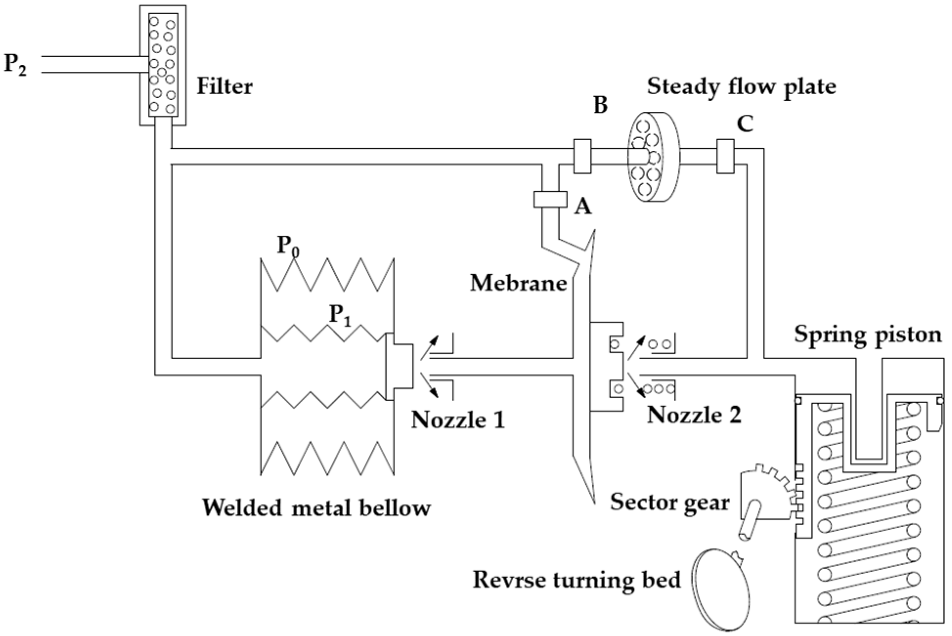
A two-stage pressure control vent valve is a pneumatic valve applied to an aero engine which is composed of an inlet joint, filter, welded metal bellow, middle support, center housing, reverse turning bed and piston chamber. The gas enters the valve through the intake joint, and the filter blocks the large particles in the gas entering the system. The welded metal bellow is a pressure-sensitive element in the system, which is compared to the control gas pressure and environmental pressure to produce displacement. The first pressure control is composed of a welded metal bellow and nozzle of middle support, and the second pressure control is composed of a membrane assembly and the nozzle of the center housing. The working principle of the vent valve is shown in Figure 1, where P0 is the ambient gas pressure, P1 is the intermediate gas pressure of the welded metal bellow and P2 is the control gas pressure. The control gas enters the system after passing through the filter, and the first gas enters the inner control chamber of the welded metal bellow to control the displacement of the welded metal bellow. The second gas enters the middle support through the damping hole A and is discharged to the outside world by the nozzle of the middle support. The third gas passes through the damping hole B, the stabilizer plate and the damping hole C into the front nozzle of the film and the piston chamber. In summary, the structure in a certain environmental pressure P0, through the input control pressure adjustment piston chamber pressure, adjusts the angle of the valve plate so as to control the piston movement of the piston chamber, completing the valve’s opening and closing action.
The exhaust valve is a complex pneumatic system with many components. The working characteristics of the components such as the membrane assembly, steady flow plate and welded metal bellow are not clear. It is necessary to obtain the characteristics of each valve component and model the two-stage pressure control valve as a whole.
2.2. Welded Metal bellow Components
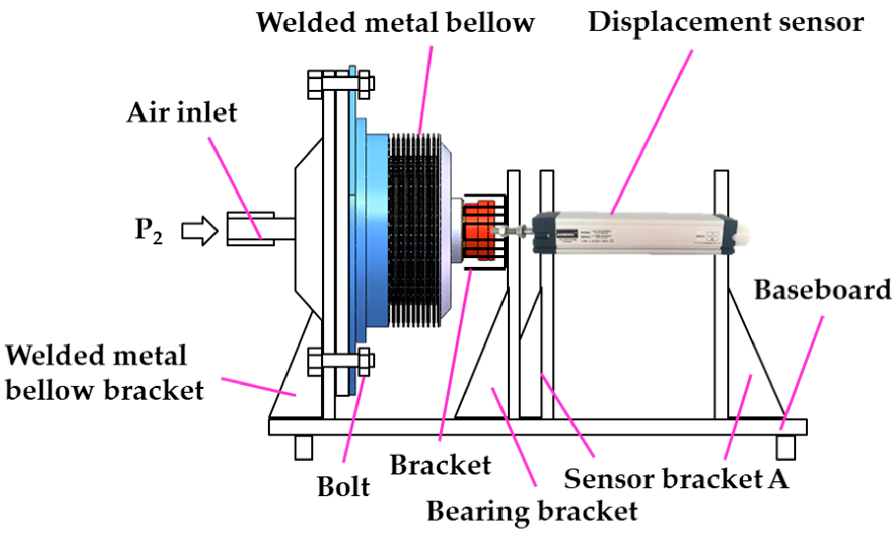
The welded metal bellow is one of the pressure-sensitive elements in the vent valve with high sensitivity and good linearity. The pressure displacement characteristics of the welded metal bellow have an important influence on the control of the valve. The pressure displacement characteristics of the test rig of the welded metal bellow shown in Figure 2 were used to measure the displacement of different control pressures. The welded metal bellow was placed in a true empty chamber to simulate different ambient pressures, and the pressure ratio and displacement characteristics were obtained. Due to the mechanical friction, there was hysteresis between the welded metal bellow’s exit and return. A linear equation with a Pearson correlation coefficient greater than 0.99 was obtained through fitting. The pressure–displacement expression of the welded metal bellow at the exit is shown in Equation (1), and the pressure–displacement expression at the return is shown in Equation (2). The errors of the pressure–displacement data and the fitting formula were within 0.06–0.08 mm.
According to Equations (1) and (2), the zero-pressure ratio of the welded metal bellow at the exit was 5.57, and the zero-pressure ratio at the return was 5.74. The errors between the zero-pressure ratio and the theoretical calculation result of 5.58 were 0.2 % and 2.9%, respectively. The average equivalent stiffness of the welded metal bellow was 43.17 N/mm from the test results.
2.3. Membrane Assembly
The membrane assembly is one of the pressure-sensitive elements in the vent valve. The membrane is a circular sheet made of rubber, which is the core deformation element in the membrane assembly. In the film assembly, the material of the diaphragm is rubber, and the rest of the structure is stainless steel, all of which are isotropic materials. Combined with the working principle of membrane assembly, the deformation can be described by Hooke’s law; that is, within the range of linear elasticity of a material, the unidirectional tensile deformation of a solid is proportional to the external force, and the mathematical model for this is shown in Equation (3). Rubber is a kind of hyperelastic material. The Mooney–Rivlin strain energy function is widely used to simulate the mechanical behavior of rubber. The constitutive equation is shown in Equation (4), and the typical binomial third-order expansion is shown in Equation (5). The membrane material is butadiene rubber, whose density ρ1 is 1200 kg/m3, elastic modulus E1 is 14.04 MPa, Poisson’s ratio μ1 is 0.499, friction coefficient ζ is 0.2, constant C1 is 1.87 and constant C2 is 0.47 in the Mooney–Rivlin material model. The rest of the structure is structural steel, whose density ρ2 is 7850 kg/m3, Young’s modulus E2 is 2 × 10⁵ MPa and Poisson’s ratio μ2 is 0.3. According to the actual working conditions, the membrane assembly exerts internal control pressure and adds fixed constraints on the outer annular surface:
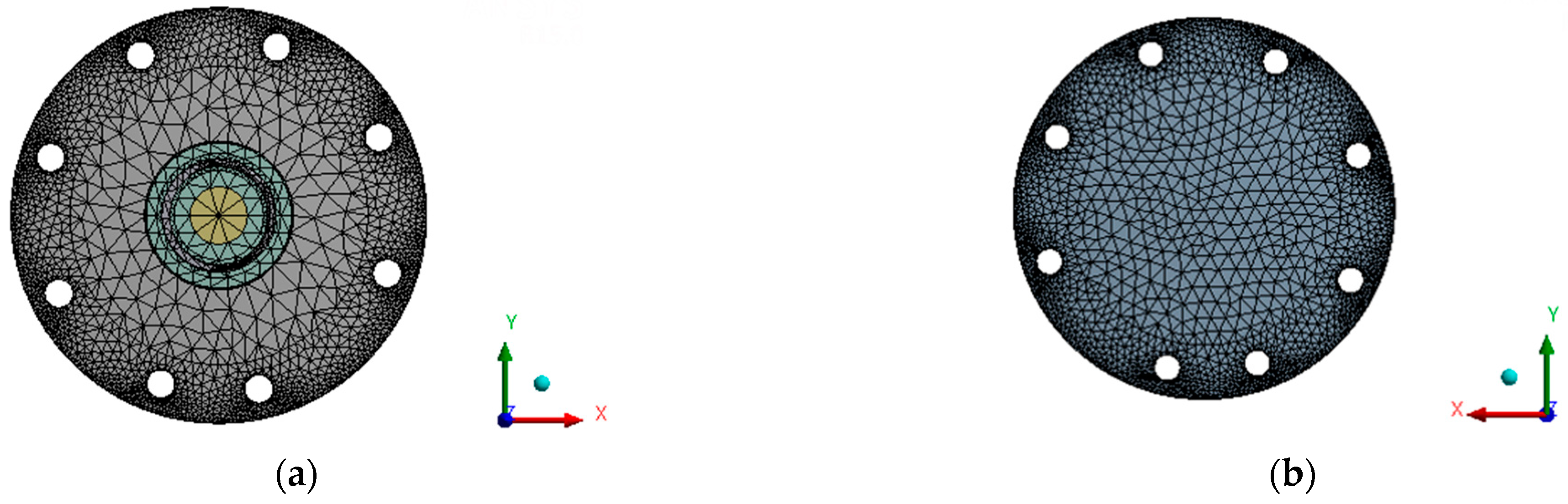
For the same physical model, the smaller the grid size is, the more grids will be obtained, and the calculation results will be more accurate. However, too many grids will only increase the computing time of the computer, so grid independence analysis of the model is needed. Through the refinement of the grid and the simulation of 0.6-mm, 0.8-mm and 1.0-mm grid sizes, the results show that the change of the result was within 5% when the grid size was 0.8 mm, and the time was short. When the grid size was 0.8 mm, the grid division of the film assembly obtained is shown in Figure 3, with 262,246 nodes and 179,929 grids.
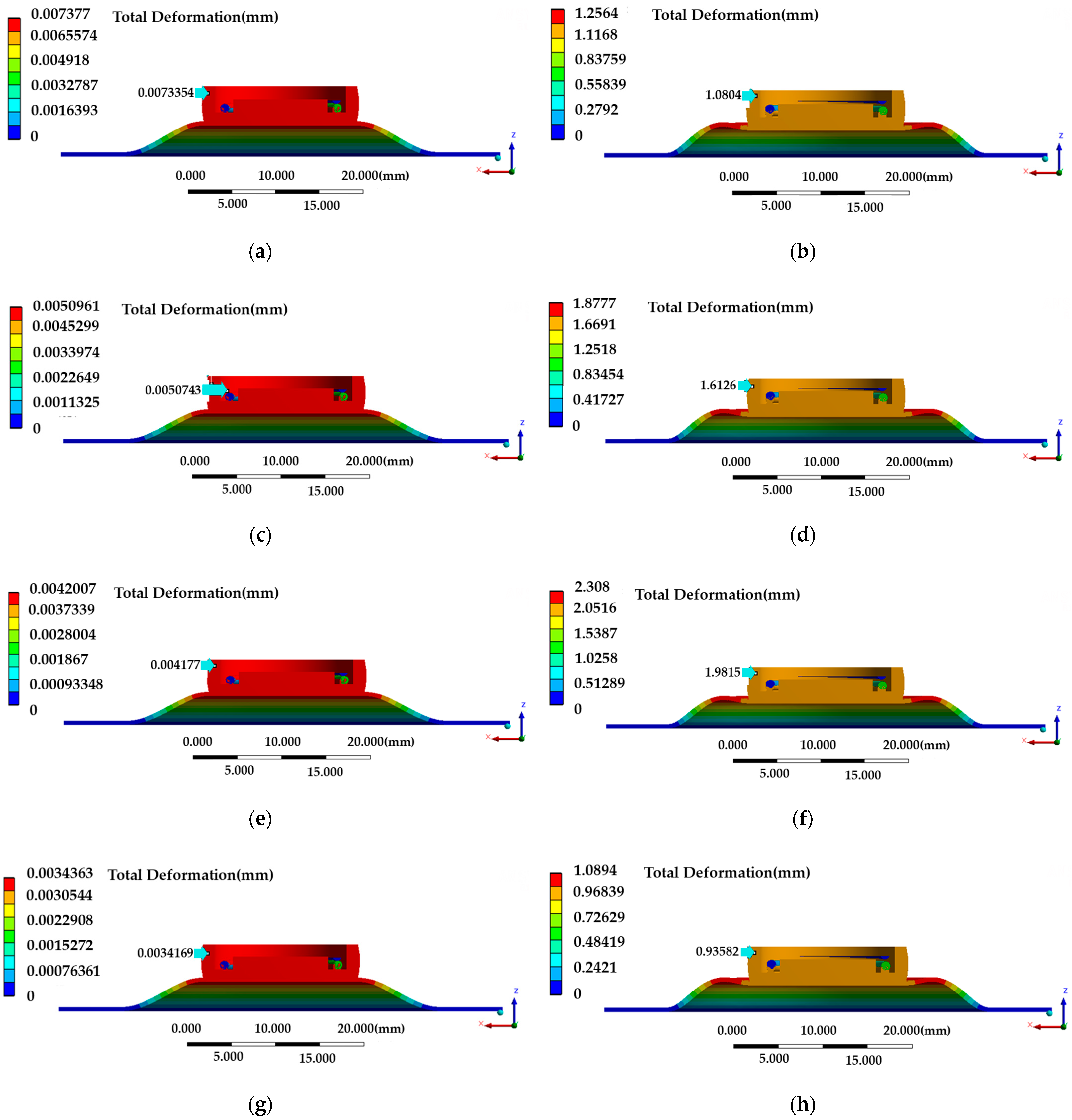
An aircraft operates at different altitudes, and different altitudes correspond to different environmental pressures. Therefore, the terminal displacement of the membrane assembly caused by the changing control pressure was simulated under different environmental pressures. Figure 4 shows the partial deformation distribution of the membrane assembly with control pressure. According to the deformation distribution cloud diagram, the maximum deformation was on the diaphragm around the terminal and not the terminal itself, so the diaphragm was the main deformation element of the membrane assembly.
According to the working characteristics of the membrane assembly, the maximum distance between the terminal and the nozzle was 0.8 mm. Therefore, the displacement of the deformation greater than 0.8 mm was actually 0.8 mm. The simulation results of the terminal displacement under different environmental pressures and control pressures were fitted. The terminal displacement under different environmental pressures was linearly correlated with the control pressures, and this result verifies that the membrane assembly conformed to the generalized Hooke’s law. From, the unary linear equation obtained from the analysis and fitting, it could be found that the slope was the same, and there was a certain proportional relationship between the intercept and the environmental pressure. Finally, the general mathematical expression of the film module is obtained as Equation (6).
In the working process of the membrane assembly, it could be regarded as the membrane and the spring in series, and the compression area s was 1017.88 mm2. Through Equation (6), the overall stiffness of the membrane assembly could be obtained as K = 6.33 N/mm, the stiffness of the spring Kb was 2.5 N/mm, and the equivalent stiffness of the film Ka was 0.169 N/mm:
where, y2 is the displacement of the terminal, P2 is the control pressure and P0 is the ambient pressure.
2.4. Steady Flow Plate
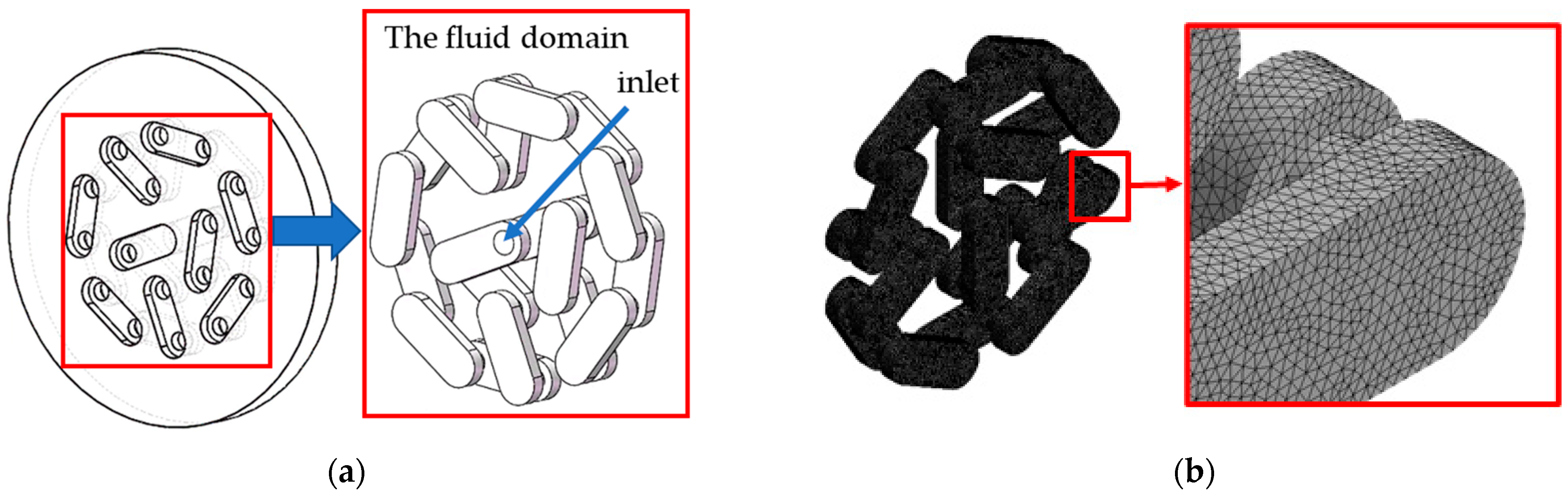
The structure of the steady flow plate is very complicated. In order to facilitate the numerical calculation of the two-stage divider valve, it is equivalent to a damping hole by means of finite element analysis [28]. The structure and flow field of the steady flow plate are shown in Figure 5a, and the meshing results are shown in Figure 5b. In order to avoid the influence of the mesh size and number on the simulation results, the simulation results of 377,051 and 516,551 grids were used, respectively. The results show that the volume flow of the equivalent damping holes was 1.5% different under the two kinds of grids, and the influence of the mesh number on the simulation results could be ignored.
The basic laws describing fluid motion include a continuity equation and Navier–Stokes equations, as shown in Equations (7) and (8), respectively. There was a fully developed turbulent field inside the steady flow plate, so the standard k-ε model was applied with high precision to the fully developed turbulent field. This model was based on the model transport equations for the turbulence kinetic energy (k) and dissipation rate (ε), as shown in Equations (9) and (10), respectively.
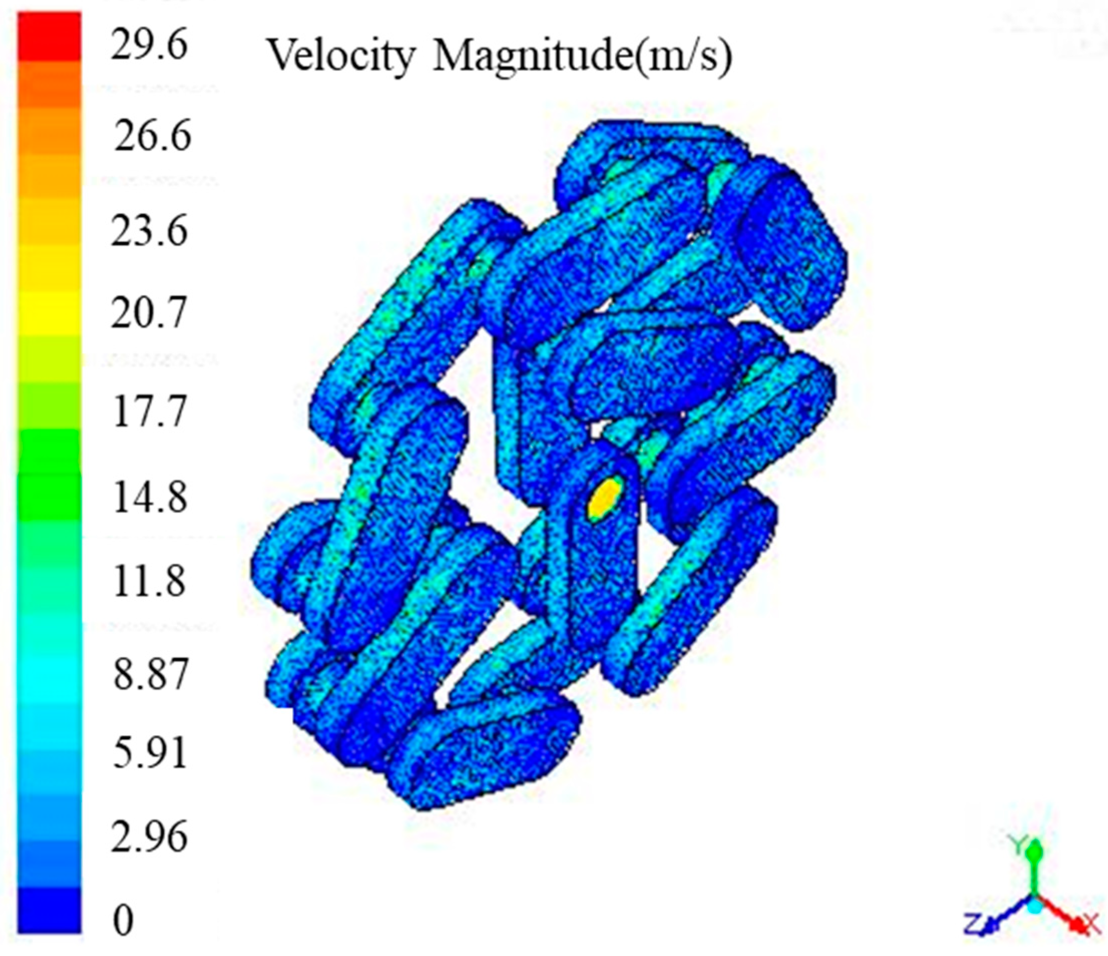
It is known that the working medium of the vent valve is air, whose density is 1.225 kg/m3 and kinematic viscosity is 1.7894 × 10⁻⁵ kg/m·s. In order to analyze the influence of different pressure differences on the mass flow, the outlet pressure was 0.1 MPa, the inlet pressure was different, and the velocity distribution in the flow field is shown in Figure 6. As can be seen from the Figure 6, the velocity value was the largest at the entrance, and the velocity was evenly distributed at other locations. The mass flow rate at different pressure ratios was obtained at the outlet pressure of 0.1 MPa.
To equate the steady flow plate with the damping hole, the mass flow-to-pressure ratio formula was required, and this is shown in Equation (11):
where C0 is 0.72, T0 is 293.15 K, b is 0.528. the gas constant R is 286.69 J/(kg·K), the specific heat capacity is at a temperature of 290 K, and the pressure of 0.1 MPa is 1.402 kJ/(kg·K).
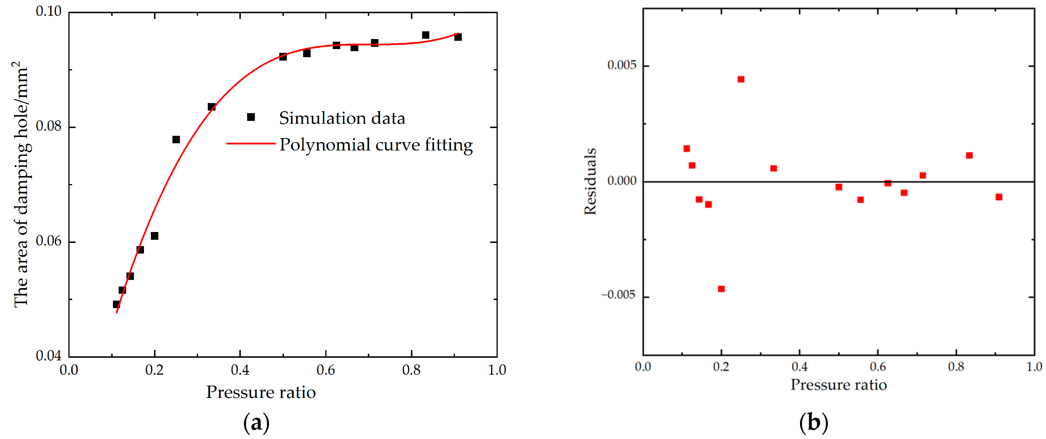
According to Equation (11), the equivalent damping hole area of different inlet pressures with an outlet pressure of 0.1 MPa could be obtained. The calculated results were fitted with the ratio of the outlet pressure and inlet pressure by a cubic polynomial. The fitting curve is shown in Figure 7, and the curve’s formula is shown in Equation (12). The coefficient of determination R2 of the fitting equation was 0.9896 > 0.9, and the fitting result was considered to be good.
2.5. Piston Chamber
In the two-stage partial pressure control valve, the piston chamber is mainly composed of a piston, spring and sector gear. The role of the piston chamber is to convert the gas pressure into the displacement of the piston, driving the rack to move so that the gear rotates and then makes the valve flap open. In the process of piston movement, the pressure of the gas needs to overcome the friction of the piston, the spring force, the friction of reproduction of rotation, etc.
In the piston chamber, the static friction force of the piston and the outer cylinder Ff was 40 N, the static friction force was 1.5 times the dynamic friction force, the outer diameter of the piston was 30.2 mm, the pressure of the piston movement was 0.25~0.35 MPa, the preload force of the spring Fy was 66.5 N, the rebound force was 139 N, and the stroke of the piston was 20 mm. Thus, the spring stiffness k was 3.625 N/mm.
2.6. Integral Model of the Vent Valve
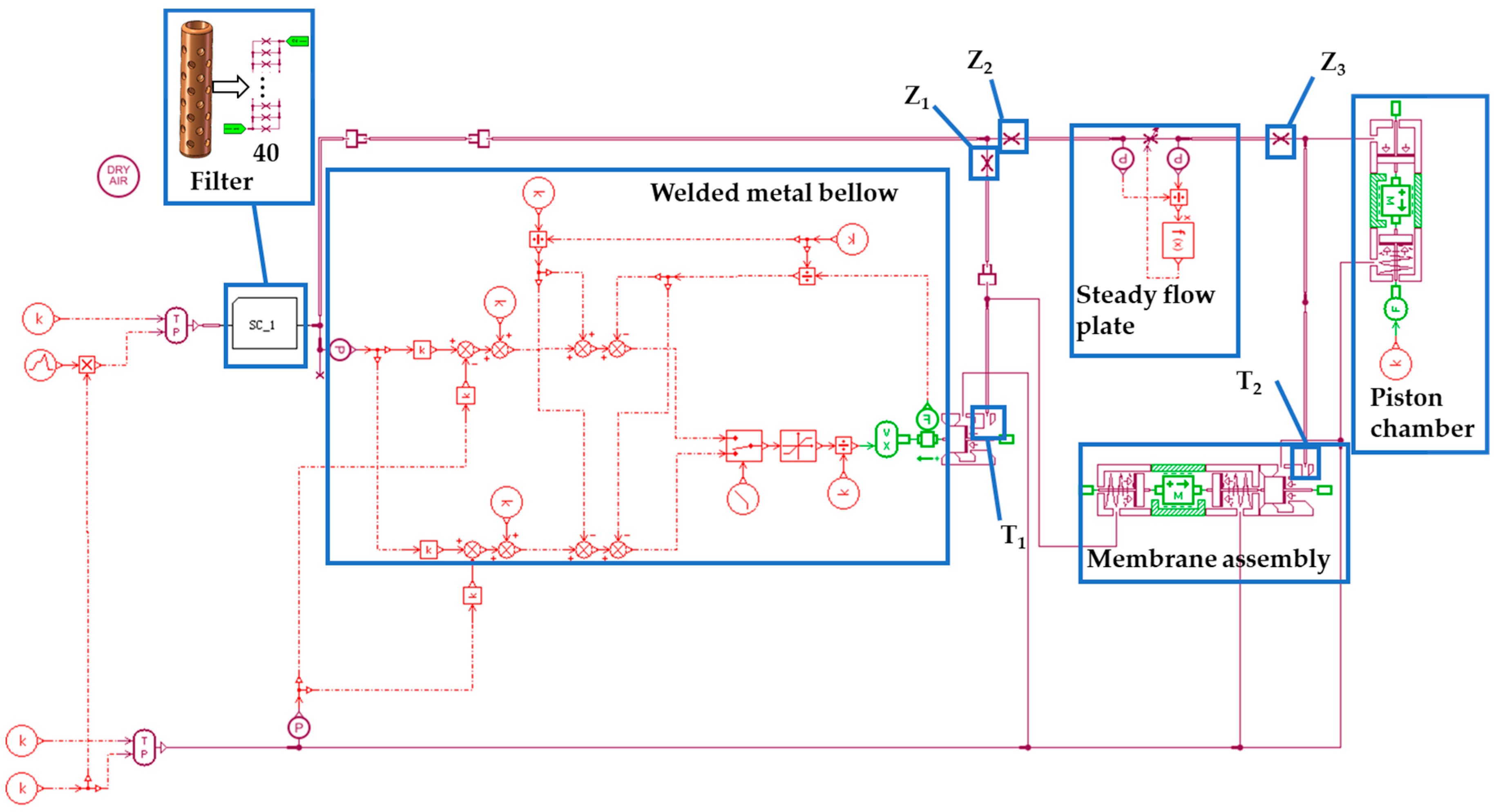
The whole structure is modeled by the working principle of the valve controlled by two-stage partial pressure and the analysis results of each component in the valve. The valve opening process was simulated with a slope signal of 1–7.5 in 0–4 s, and the closing action was simulated with a slope signal of 7.5–1 in 4–8 s. The overall model of the vent valve was obtained as shown in Figure 8. The damping hole is a small hole or a micro-hole which has the functions of throttling, regulating pressure, buffering and shock-proofing in the system. The damping hole is extremely important for adjusting the opening and closing performance of the two-stage pressure control valve. As shown in Figure 8, Z1 is the diameter of damping hole A, Z2 is the diameter of damping hole B, and Z3 is the diameter of damping hole C. Different sizes of nozzle diameters will also produce system damping, which has an important impact on the pressure transfer of the valve. T1 is the diameter of the middle nozzle 1, and T2 is the diameter of nozzle 2. The parameterized simulation method was used to simulate the different sizes of damping holes and nozzle diameters, and the parameters in the opening and closing process of the valve were obtained.
2.7. Experiment
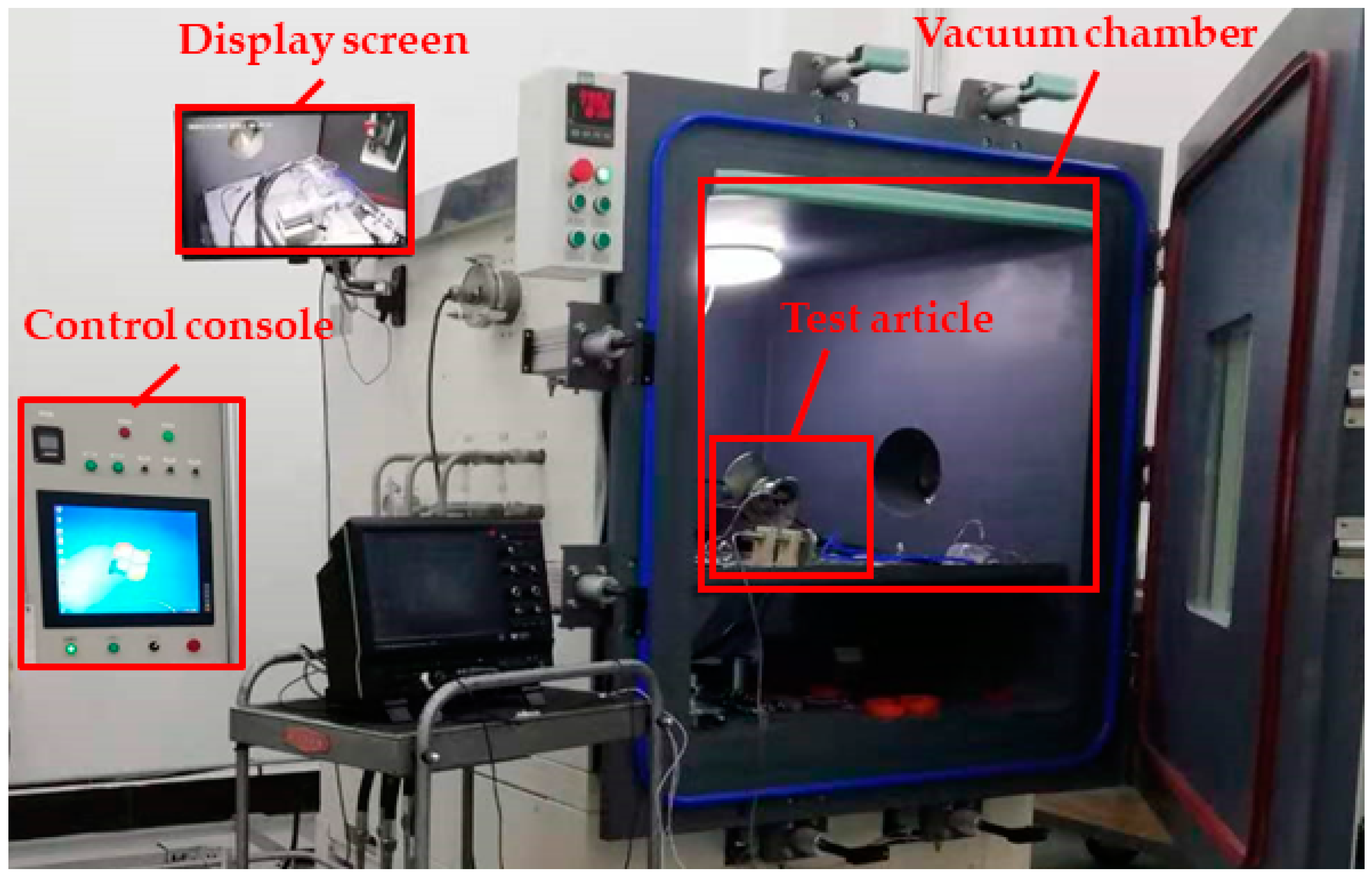
In order to verify the accuracy of the simulation results, the opening and closing characteristics of the valve were tested in a vacuum chamber. Figure 9 shows the test bed for the opening and closing characteristics of the vent valve. The control console was used to control the pressure of the empty chamber and the control pressure of the valve, and the opening and closing condition of the valve was observed to extract the pressure ratio in the opening and closing process.
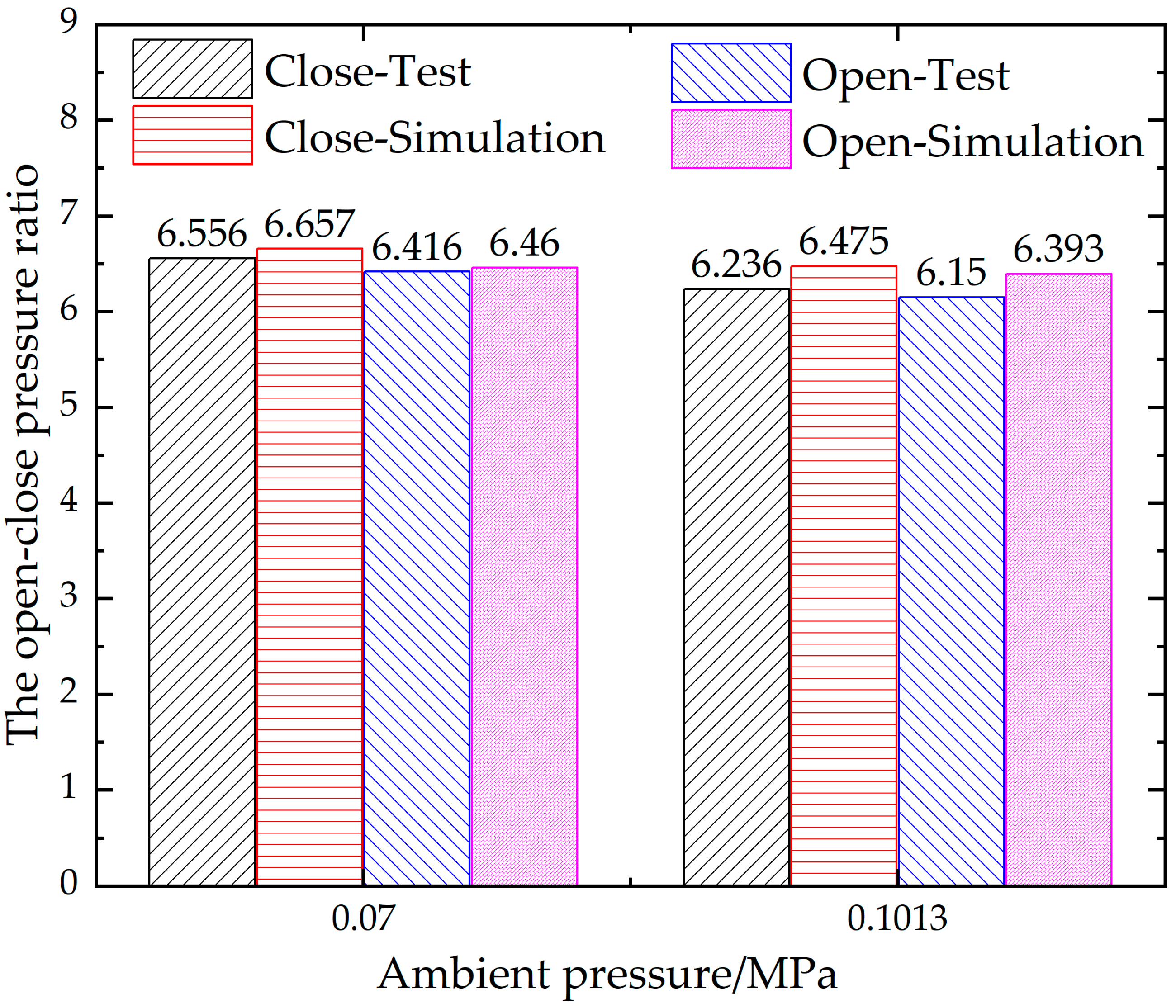
The control pressure ratio of the valve at 0.1013 MPa and 0.07 MPa was obtained through the test. The valve opening and closing for two cycles was taken as a measurement cycle. A total of five cycles were measured, and the average value of the pressure ratio was the final result. Figure 10 shows the open-close pressure ratio of the vent valve obtained through the test and simulation. The error between the simulation results and the test results was within 5%, which verifies the reliability of the simulation model. The valve closed pressure ratio was slightly higher than the open pressure ratio. This was due to the hysteresis of the metal diaphragm.
3. Results
3.1. Different Diameters of Damping Hole A
The damping hole A is located at the front end of the middle nozzle of the support. Figure 11 shows the opening and closing characteristic curves of the valve under different shell damping hole diameters. It can be seen from Figure 11a that, with the increase in diameter of damping hole A, the middle pressure of the support began to rise when the control pressure was small. When it rose to a certain value, the middle pressure of the support rapidly rose to equal the control pressure, which was especially obvious when Z1 was equal to 3.0 mm. It can be seen from Figure 11b that the pressure of the piston control chamber would have a sudden increase or decrease, which is the key to controlling the opening and closing of the valve. With the increase in diameter of damping hole A, the control pressure required by this sudden change point would decrease. From Figure 11c,d, it can be seen that the complete opening and closing action of the valve led to a mutation in the control chamber pressure, characterized by the change in the piston displacement, when Z1 was equal to a 1.0-mm piston displacement, along with the change in the piston chamber pressure leading to a small oscillation appearing. The oscillation was most serious when Z1 was 3 mm and the most stable when Z1 was equal to 0.5 mm because damping hole A was small, which required a great deal of control pressure for the piston to move. Therefore, the recommended size for damping hole A is between 0.1 mm and 1.0 mm.
3.2. Different Diameters of Damping Hole B
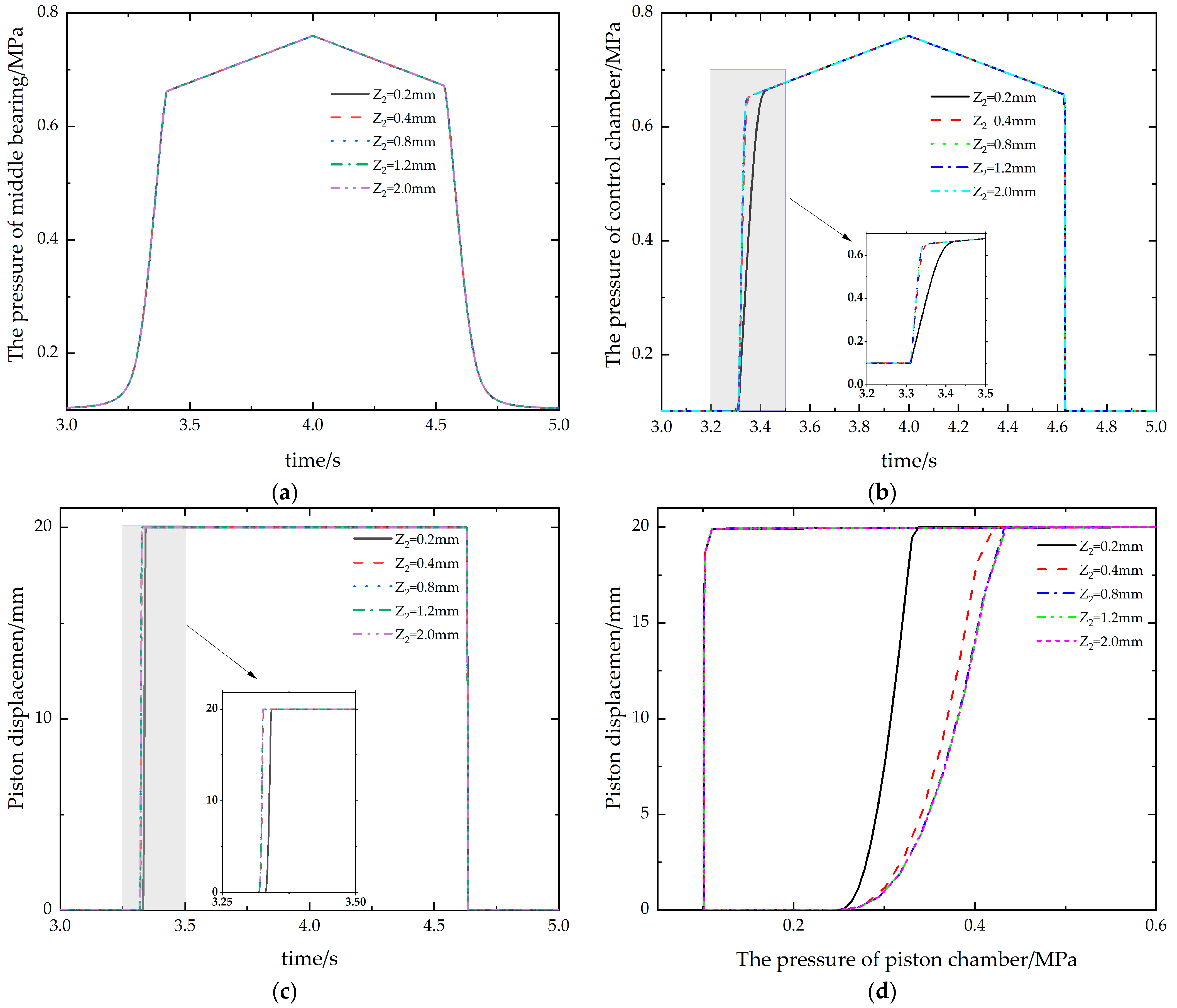
Damping hole B is located in front of the steady flow plate. Figure 12 shows the opening and closing characteristic curves of the valve under different damping hole diameters for damping hole B. According to Figure 12a, as the diameter of damping hole B changed, the middle pressure of the support changed with the same rule over time. It can be seen from Figure 12b that with the change in diameter of damping hole B, the change law of the piston chamber pressure did not change in the closing process of the valve. In the opening process, the lag phenomenon occurred when the piston chamber reached the control pressure with the decrease in diameter of the damping hole, which was more obvious when Z2 was equal to 0.2 mm. It can be seen from Figure 12c,d that as the diameter of damping hole B decreased, the opening time of the valve would increase a little, and the control pressure in the piston chamber decreased when it was fully opened because the pressure in the control chamber rose slowly with time. To ensure that the control gas pressure could be smoothly transferred to the piston chamber, the diameter of damping hole B should be greater than 0.4 mm.
3.3. Different Diameters of Damping Hole C
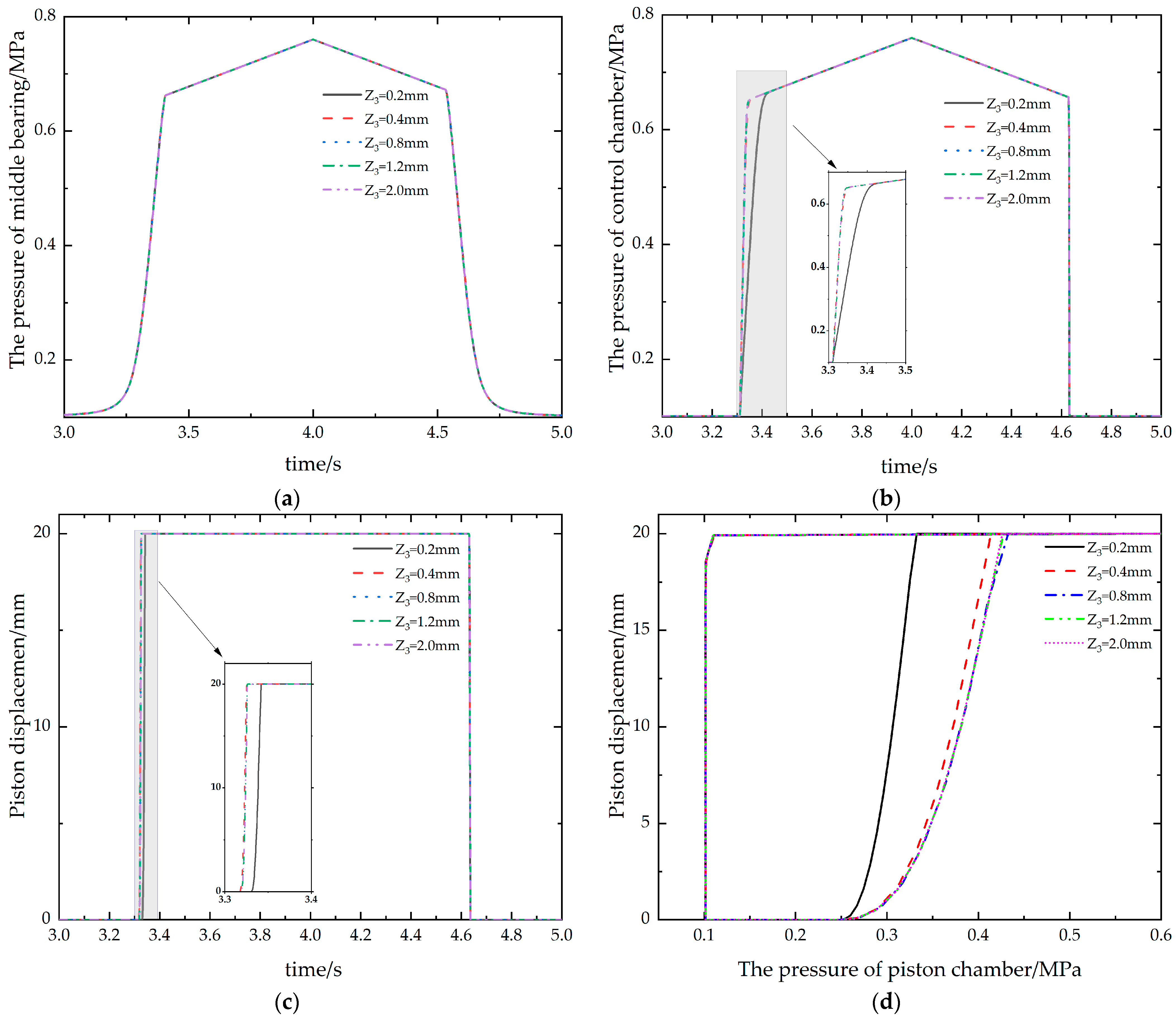
Damping hole C is located behind the steady flow plate. Figure 13 shows the opening and closing characteristic curves of the valve under different damping hole diameters for the rear throttle plate. It can be seen from the curve shown in the Figure 13 that damping holes B and C had the same influence on the opening and closing characteristics of the vent valve, which also reflected the role of the stabilizer plate from the side.
3.4. Different Diameters of Middle Nozzle 1
The nozzle is also an important damping component in the vent valve system. The diameter of the nozzle has an important influence on the pressure transmission and control of the system [28]. Middle nozzle 1 is the key to the first pressure control of the vent valve. Figure 14 shows the opening and closing characteristic curves of the valve under the middle nozzle diameters of different supports. From Figure 14a, with the decrease in the middle nozzle diameter, the middle pressure rising time decreased. When T1 was equal to 0.5 mm, the middle pressure of the support began to increase at 0, but the mutation point of the middle pressure of the support did not change. With the increase in the diameter of T1, the time for the middle pressure of the support to reach the control pressure increased because the jet flow and pressure loss in front of the nozzle changed. It can be seen from Figure 14b that with the increase in diameter of nozzle 1, the pressure in the piston chamber increased gradually when it reached the mutation point of the control pressure. According to Figure 14c,d, as the diameter of nozzle 1 decreased, the control pressure decreased when the valve was opened and closed. When T1 was equal to 0.5 mm, the pressure of the piston chamber was small when the valve was fully opened, which is not conducive to the opening and closing of the valve. Combined with Figure 14a,b, it can be seen that in the opening and closing process when T1 was 0.5 mm, the middle pressure of the support did not reach the mutation point, so there would be a large energy loss at T1. It can be seen from Figure 14d that the opening and closing process of the valve was most stable when T1 was 2.8 mm, so the recommended diameter of middle nozzle 1 is 2.8 mm, and the control performance within 1.0~5.0 mm is also acceptable.
3.5. Different Diameters of Nozzle 2
Nozzle 2 is located at the back end of the membrane assembly and is the key element of the second stage of pressure control. Figure 15 shows the opening and closing characteristic curves of the nozzle diameters of the middle shell under different conditions. It can be seen from Figure 15a that the variation rule of the middle pressure of the support was not affected by the diameter of nozzle 2. As can be seen from Figure 15b, with the decrease in diameter of nozzle 2, the pressure mutation point of the piston chamber decreased slightly when the valve was closed. When T2 was equal to 1.0 mm, there was always a small preloaded pressure in the piston chamber, which was caused by the nozzle being too small. As can be seen from Figure 15c,d, with the increase in the nozzle diameter of the middle shell, the stability of the valve in the closing process gradually decreased, especially when T2 was 9.0 mm, which seriously affected the performance of the vent valve. Preload pressure in the piston chamber caused the valve to open with less pressure when T2 was equal to 1.0 mm. Therefore, the recommended diameter of the middle shell nozzle is 2.5~6.0 mm.
4. Conclusions
Vent valves open and close by a two-stage pressure type pneumatic system and control. The main role of the vent valve is to prevent surges in aircraft engines. The influence of different damping parameters in the valve on the characteristics of the control valve was obtained by the method of parametric simulation through the establishment of the vent valve model. The results show that the damping parameters had a great influence on the control characteristics of the valve, and the conclusions are as follows:
- (1)
- In the process of using the vent valve, there was a pressure mutation point in the middle support pressure and the pressure in the control chamber, which made the piston chamber pressure change rapidly and made the vent valve open and close with good rapidness.
- (2)
- The damping parameters will affect the control performance of the vent valve, among which Z1 and T1 are the main components. With the increase in Z1, the middle pressure of the support will increase in advance, and the rate will increase rapidly after a turning point. The increase in the diameter Z1 can reduce the pressure surge point of the piston chamber. There will be serious instability in the closing process of the vent valve when Z1 is too large. The piston chamber needs a lot of pressure to complete the opening and closing action when Z1 is too small. The recommended size of Z1 is between 0.1 mm and 1.0 mm. The increase in T1 will increase the time for the middle support pressure to reach the control pressure and increase the piston chamber to the transition point of the control pressure. The best recommended diameter for the middle nozzle of the support is 2.8 mm, and a control performance within 1.0~5.0 mm is also acceptable.
- (3)
- Z2 and Z3 are distributed before and after the steady flow plate and have little influence on the opening and closing characteristics of the vent valve, and the influence law is the same. With the decrease in the diameter of the damping hole, the piston chamber reaches the control pressure time lag, which is not conducive to the effective control of the valve opening and closing. According to the simulation results, the diameter of the damping hole of the front throttle plate should be greater than 0.4 mm. The increase in T2 will make the valve unstable during the opening process, and a T2 value that is too small will cause a pre-pressure in the piston chamber. The recommended diameter for T2 is from 2.5 mm to 6.0 mm.
Author Contributions
Conceptualization, J.Z.; methodology, J.Z. and W.Y.; software, L.P. and Z.G.; validation, J.Z., Y.S. and Y.L.; formal analysis, Y.L.; investigation, Z.G.; resources, Y.S., L.P. and Z.G.; data curation, W.Y.; writing—original draft preparation, J.Z. and W.Y.; writing—review and editing, J.Z., W.Y. and Y.L.; visualization, Y.S., L.P. and Z.G.; supervision, J.Z.; project administration, J.Z.; funding acquisition, J.Z. All authors have read and agreed to the published version of the manuscript.
Funding
This research was funded by the National Natural Science Foundation of China (NSFC) (grant numbers 51890881 and 52005429).
Data Availability Statement
Not applicable.
Conflicts of Interest
The authors declare no conflict of interest.
Abbreviations
| VBV | variable bleed valve |
| PCGV | pilot control globe valve |
| PRV | pilot pressure-reducing valve |
| P0 | ambient gas pressure (MPa) |
| P1 | intermediate gas pressure of welded metal bellow (MPa) |
| P2 | control gas pressure (MPa) |
| A | damping hole A |
| B | damping hole B |
| C | damping hole C |
| k | pressure ratio (P2/P0) |
| y1 | displacement of the welded metal bellow bracket |
| ρ | density (kg/m3) |
| E | elastic modulus (MPa) |
| μi | Poisson’s ratio |
| ζ | friction coefficient |
| [K] | system structural stiffness matrix |
| {δ}, | displacement array of system nodes |
| {F} | load array |
| W | strain energy density |
| N | series of functions |
| Cij | material constant |
| I1 | first-order strain invariant |
| I2 | second-order strain invariant |
| I3 | third-order strain invariant |
| J | volume ratio |
| dk | material constant |
| C1, C2 | material constants |
| y2 | displacement of the terminal (mm) |
| t | time |
| u, v, w | velocity vector |
| x, y, z | cartesian direction |
| μ | dynamic viscosity |
| p | pressure |
| Su, Sv, Sw | generalized source terms of momentum equation |
| Gk | turbulent kinetic energy generated by average speed |
| Gb | turbulent kinetic energy from buoyancy |
| YM | the contribution of the fluctuating dilatation in compressible turbulence to the overall dissipation rate |
| C1ε, C2ε, C3ε | constants |
| σk | the turbulent Prandtl number for k |
| σε | the turbulent Prandtl number for ε |
| Sk | user-defined source term for k |
| Sε | user-defined source term forε |
| μt | turbulent viscosity |
| s | compression area (mm2) |
| K | overall stiffness of the membrane assembly (N/mm) |
| Ka | equivalent stiffness of the film (N/mm) |
| Kb | stiffness of the spring (N/mm) |
| Qm | mass flow (kg/s) |
| C0 | flow coefficient |
| S | orifice area (mm2) |
| p0 | pressure before the orifice (MPa) |
| p1 | pressure after the orifice (MPa) |
| γ | specific heat capacity of air (kJ/(kg·K)) |
| R | gas constant (J/(kg K)) |
| T0 | absolute temperature of the upstream air (K) |
| b | Constant |
| Ff | static friction force (N) |
| Fy | preload force (N) |
| Z1 | diameter of the damping hole of the middle shell |
| Z2 | diameter of the damping hole in front of the steady flow plate |
| Z3 | diameter of the damping hole behind the steady flow plate |
| T1 | diameter of the middle nozzle of the support |
| T2 | diameter of the nozzle of the middle shell |
References
- Yan, W.; Hu, J.; Zhang, H.; Mao, Z.; Yin, C.; Chenkai, Z. Effects of Complicated Rotating Inlet Distortion on Compressor Aerodynamic Stability. In Proceedings of the 50th AIAA/ASME/SAE/ASEE Joint Propulsion Conference, Cleveland, OH, USA, 28–30 July 2014; p. 3732. [Google Scholar]
- Lee, K.; Lee, B.; Kang, S.; Yang, S.; Lee, D. Inlet distortion test with gas turbine engine in the altitude engine test facility. In Proceedings of the 27th AIAA Aerodynamic Measurement Technology and Ground Testing Conference, Chicago, IL, USA, 28 June–1 July 2010; p. 4337. [Google Scholar]
- Sohail, M.U.; Hamdani, H.R.; Islam, A.; Parvez, K.; Khan, A.M.; Allauddin, U.; Khurram, M.; Elahi, H. Prediction of Non-Uniform Distorted Flows, Effects on Transonic Compressor Using CFD, Regression Analysis and Artificial Neural Networks. Appl. Sci. 2021, 11, 3706. [Google Scholar] [CrossRef]
- Leinhos, D.C.; Schmid, N.R.; Fottner, L. The Influence of Transient Inlet Distortions on the Instability Inception of a Low-Pressure Compressor in a Turbofan Engine. J. Turbomach. 2000, 123, 1–8. [Google Scholar] [CrossRef]
- Longley, J.P. A Review of Nonsteady Flow Models for Compressor Stability. J. Turbomach. 1994, 116, 202–215. [Google Scholar] [CrossRef]
- Longley, J.P.; Shin, H.-W.; Plumley, R.E.; Silkowski, P.D.; Day, I.J.; Greitzer, E.M.; Tan, C.S.; Wisler, D.C. Effects of Rotating Inlet Distortion on Multistage Compressor Stability. J. Turbomach. 1996, 118, 181–188. [Google Scholar] [CrossRef]
- Tan, Y. Fitting Operation Curve of Civil Aviation Turbo-fan Engine’s Variable Bleed Valve based on MATLAB. J. Phys. Conf. Ser. 2019, 1176, 52040. [Google Scholar] [CrossRef]
- Song, X.G.; Cui, L.; Park, Y.C. Three-Dimensional CFD Analysis of a Spring-Loaded Pressure Safety Valve from Opening to Re-Closure. In Proceedings of the ASME 2010 Pressure Vessels and Piping Division/K-PVP Conference, Washington, DC, USA, 18–22 July 2010; pp. 295–303. [Google Scholar]
- Sibilla, S.; Gallati, M. Hydrodynamic Characterization of a Nozzle Check Valve by Numerical Simulation. J. Fluids Eng. 2008, 130, 121101. [Google Scholar] [CrossRef]
- Shuiting, D.; Tian, Q.; Xiaofeng, L.; Shuguang, Z. FHA method for VBV position control function of FADEC system based on aero-engine dynamic model. Procedia Eng. 2011, 17, 567–579. [Google Scholar] [CrossRef] [Green Version]
- Shiao, Y.; Kantipudi, M.B.; Yang, T.-H. Performance estimation of an engine with magnetorheological variable valve train. Adv. Mech. Eng. 2019, 11, 1687814019847795. [Google Scholar] [CrossRef] [Green Version]
- Zhang, Y.; Xiao, Y.; Zhang, S.; Yin, Y.; Wang, C. Numerical evaluation on aerodynamic design of pressure-regulating valve in trisonic intermittent wind tunnel. Adv. Mech. Eng. 2021, 13, 16878140211041007. [Google Scholar] [CrossRef]
- Zhang, X.; Zhu, Z.; Xiang, N.; Ni, Z. A microfluidic gas damper for stabilizing gas pressure in portable microfluidic systems. Biomicrofluidics 2016, 10, 054123. [Google Scholar] [CrossRef] [Green Version]
- Zhang, X.; Lu, Y.; Li, Y.; Zhang, C.; Wang, R. Numerical calculation and experimental study on response characteristics of pneumatic solenoid valves. Meas. Control 2019, 52, 1382–1393. [Google Scholar] [CrossRef]
- Zhang, R.; Peng, J.; Li, H.; Chen, B.; Liu, W.; Huang, Z.; Wang, J. A predictive control method to improve pressure tracking precision and reduce valve switching for pneumatic brake systems. IET Control Theory Appl. 2021, 15, 1389–1403. [Google Scholar] [CrossRef]
- Zhipeng, X.; Xuanyin, W. Development of a novel high pressure electronic pneumatic pressure reducing valve. J. Dyn. Sys. Meas. Control. 2011, 133, 011011. [Google Scholar] [CrossRef]
- Wang, X.; Xu, Z. Concentric Annular Clearance-Controllable Pressure Characteristics Research of a High Pressure Pneumatic Pressure Assembly. Chin. J. Mech. Eng. Engl. Ed. 2011, 24, 121. [Google Scholar] [CrossRef]
- Bao, H.; Wang, Z.; Wei, X.; Li, G. Study on the Structural Configurations and Pressure Regulation Characteristics of the Automatic Pressure Regulating Valve in the Electronically Controlled Pneumatic Brake System of Commercial Vehicles. Appl. Sci. 2021, 11, 10603. [Google Scholar] [CrossRef]
- Wang, C.; Quan, L.; Ou, H. The method of restraining hydraulic impact with active adjusting variable damping. Proc. Inst. Mech. Eng. Part C J. Mech. Eng. Sci. 2019, 233, 3785–3794. [Google Scholar] [CrossRef]
- Sun, Z.-Y.; Li, G.-X.; Wang, L.; Wang, W.-H.; Gao, Q.-X.; Wang, J. Effects of structure parameters on the static electromagnetic characteristics of solenoid valve for an electronic unit pump. Energy Conv. Manag. 2016, 113, 119–130. [Google Scholar] [CrossRef]
- Ren, F.; Liu, X.; Chen, J.; Zeng, P.; Liu, B.; Wang, Q. Dynamic characteristics analysis of power shift control valve. Adv. Mech. Eng. 2014, 6, 824853. [Google Scholar] [CrossRef]
- Guan, C.; Jiao, Z.; He, S. Theoretical study of flow ripple for an aviation axial-piston pump with damping holes in the valve plate. Chin. J. Aeronaut. 2014, 27, 169–181. [Google Scholar] [CrossRef] [Green Version]
- Zeng, Q.-L.; Tian, M.-Q.; Wan, L.-R.; Dai, H.-Z.; Yang, Y.; Sun, Z.-Y.; Lu, Y.-J.; Liu, F.-Q. Characteristic analysis of digital large flow emulsion relief valve. Math. Probl. Eng. 2020, 2020, 5820812. [Google Scholar] [CrossRef]
- Qian, J.-Y.; Wu, J.-Y.; Gao, Z.-X.; Jin, Z.-J. Pilot pipe and damping orifice arrangements analysis of a pilot-control globe valve. J. Fluids Eng. 2020, 142, 101210. [Google Scholar] [CrossRef]
- Zhang, J.-H.; Wang, D.; Xu, B.; Gan, M.-Y.; Pan, M.; Yang, H.-Y. Experimental and numerical investigation of flow forces in a seat valve using a damping sleeve with orifices. J. Zhejiang Univ.Sci A 2018, 19, 417–430. [Google Scholar] [CrossRef]
- Jin, Z.-J.; Gao, Z.-X.; Zhang, M.; Qian, J.-Y. Pressure Drop Analysis of Pilot-Control Globe Valve with Different Structural Parameters. J. Fluids Eng. 2017, 139, 91102. [Google Scholar] [CrossRef]
- Jang, S.C.; Kang, J.H. Orifice design of a pilot-operated pressure relief valve. J. Press. Vessel. Technol. 2017, 139, 31601. [Google Scholar] [CrossRef]
- Hu, L.; Shen, Y.; Chen, W.; Fu, X. Experimental investigation on submerged gas-liquid mixture injection into water through a micro-channel. Int. J. Multiph. Flow 2016, 83, 39–50. [Google Scholar] [CrossRef]
Figure 1.
Schematic diagram of two-stage partial pressure relief valve.

Figure 2.
Pressure displacement test kit for welded metal bellow bracket.

Figure 3.
Result of meshing of membrane assembly: (a) Results of mesh division on spring side; (b) Diaphragm-side mesh partitioning results.
Figure 3.
Result of meshing of membrane assembly: (a) Results of mesh division on spring side; (b) Diaphragm-side mesh partitioning results.

Figure 4.
Deformation of membrane assembly with control pressure at different ambient pressures: (a) Both ambient pressure and control pressure are 0.10133 MPa; (b) The ambient pressure is 0.10133 MPa, and the control pressure is 0.107 MPa; (c) Both ambient pressure and control pressure are 0.07 MPa; (d) The ambient pressure is 0.07 MPa, and the control pressure is 0.08 MPa; (e) Both ambient pressure and control pressure are 0.0577 MPa; (f) The ambient pressure is 0.0577 MPa, and the control pressure is 0.07 MPa; (g) Both ambient pressure and control pressure are 0.0472 MPa; (h) The ambient pressure is 0.0472 MPa, and the control pressure is 0.053 MPa.

Figure 5.
Steady flow plate structure and grid: (a) Steady flow plate structure; (b) Meshing results of steady flow plate.
Figure 5.
Steady flow plate structure and grid: (a) Steady flow plate structure; (b) Meshing results of steady flow plate.

Figure 6.
Velocity distribution results of steady flow plate when inlet is 0.11 MPa and outlet is 0.1 MPa.
Figure 6.
Velocity distribution results of steady flow plate when inlet is 0.11 MPa and outlet is 0.1 MPa.

Figure 7.
The variation law of equivalent damping hole area with pressure ratio: (a) Fitting curves under different pressure ratios; (b) Residual diagram at different pressure ratios.
Figure 7.
The variation law of equivalent damping hole area with pressure ratio: (a) Fitting curves under different pressure ratios; (b) Residual diagram at different pressure ratios.

Figure 8.
Integral model of two-stage differential pressure control vent valve.

Figure 9.
Test stand for opening and closing characteristics of vent valve.

Figure 10.
Results of vent valve test and simulated open-close pressure ratio.

Figure 11.
Opening and closing characteristics of valve with different damping hole diameters: (a) The variation law of middle bearing pressure with time; (b) Control the change of cavity pressure with time; (c) The variation law of piston displacement with time; (d) The variation of piston displacement with pressure in control chamber.

Figure 12.
Opening and closing characteristics of valve with different front throttle orifice diameters: (a) The variation law of middle bearing pressure with time; (b) Control of the change in cavity pressure with time; (c) The variation law of piston displacement with time; (d) The variation of piston displacement with pressure in control chamber.

Figure 13.
Opening and closing characteristics of valve with different diameters of rear orifice: (a) The variation law of middle bearing pressure with time; (b) Control of the change in cavity pressure with time; (c) The variation law of piston displacement with time; (d) The variation of piston displacement with pressure in control chamber.

Figure 14.
Opening and closing characteristics of valve with different middle nozzle diameters: (a) The variation law of middle bearing pressure with time; (b) Control of the change in cavity pressure with time; (c) The variation law of piston displacement with time; (d) The variation of piston displacement with pressure in control chamber.

Figure 15.
Opening and closing characteristics of valve under different nozzle diameters of middle shell: (a) The variation law of middle bearing pressure with time; (b) Control of the change in cavity pressure with time; (c) The variation law of piston displacement with time; (d) The variation of piston displacement with pressure in control chamber.


Publisher’s Note: MDPI stays neutral with regard to jurisdictional claims in published maps and institutional affiliations. |
© 2022 by the authors. Licensee MDPI, Basel, Switzerland. This article is an open access article distributed under the terms and conditions of the Creative Commons Attribution (CC BY) license (https://creativecommons.org/licenses/by/4.0/).
Share and Cite
MDPI and ACS Style
Zhang, J.; Yin, W.; Shi, Y.; Gao, Z.; Pan, L.; Li, Y. Effects of the Damping Parameters on the Opening and Closing Characteristics of Vent Valves. Appl. Sci. 2022, 12, 5169. https://0-doi-org.brum.beds.ac.uk/10.3390/app12105169
AMA Style
Zhang J, Yin W, Shi Y, Gao Z, Pan L, Li Y. Effects of the Damping Parameters on the Opening and Closing Characteristics of Vent Valves. Applied Sciences. 2022; 12(10):5169. https://0-doi-org.brum.beds.ac.uk/10.3390/app12105169
Chicago/Turabian StyleZhang, Jin, Wenlong Yin, Yandong Shi, Zitong Gao, Lijiang Pan, and Ying Li. 2022. "Effects of the Damping Parameters on the Opening and Closing Characteristics of Vent Valves" Applied Sciences 12, no. 10: 5169. https://0-doi-org.brum.beds.ac.uk/10.3390/app12105169
Note that from the first issue of 2016, this journal uses article numbers instead of page numbers. See further details here.