
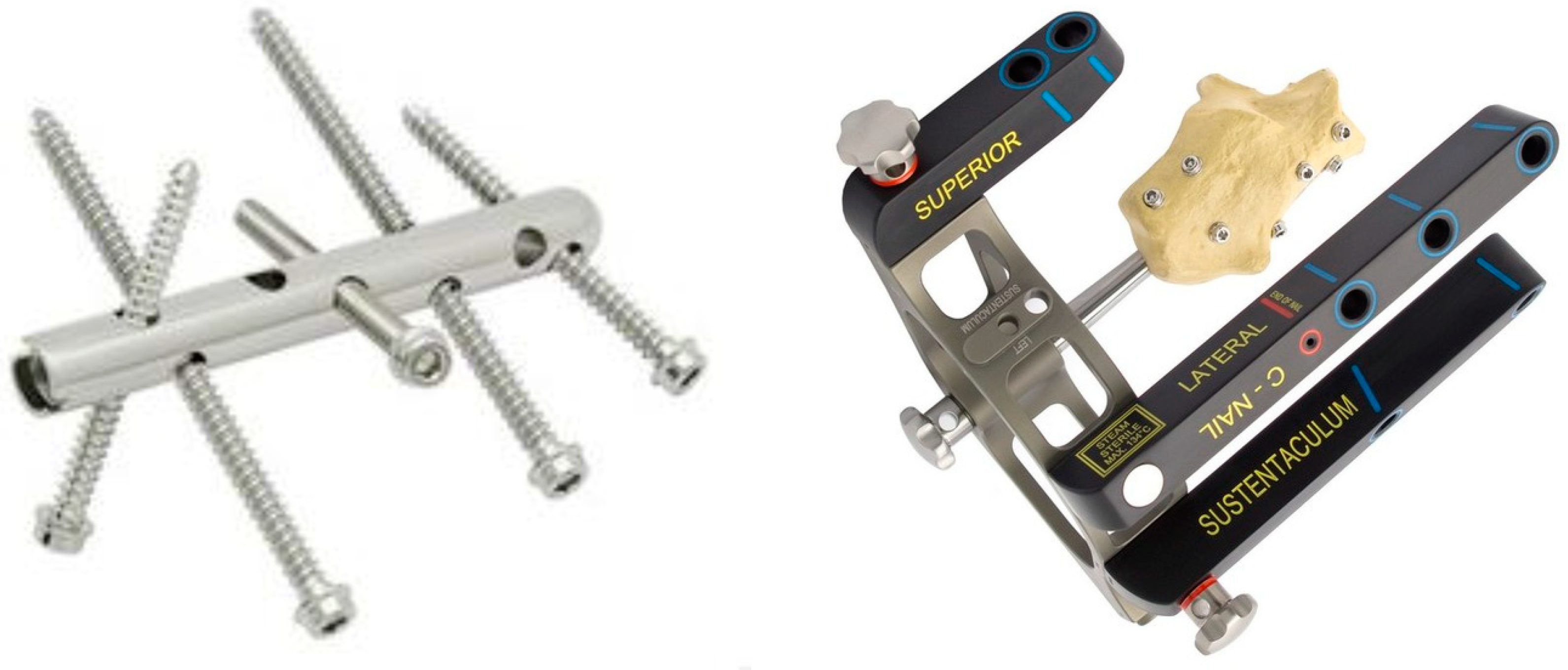
Numerical Analysis of the Calcaneal Nail C-NAIL


 , , , ,
Abstract
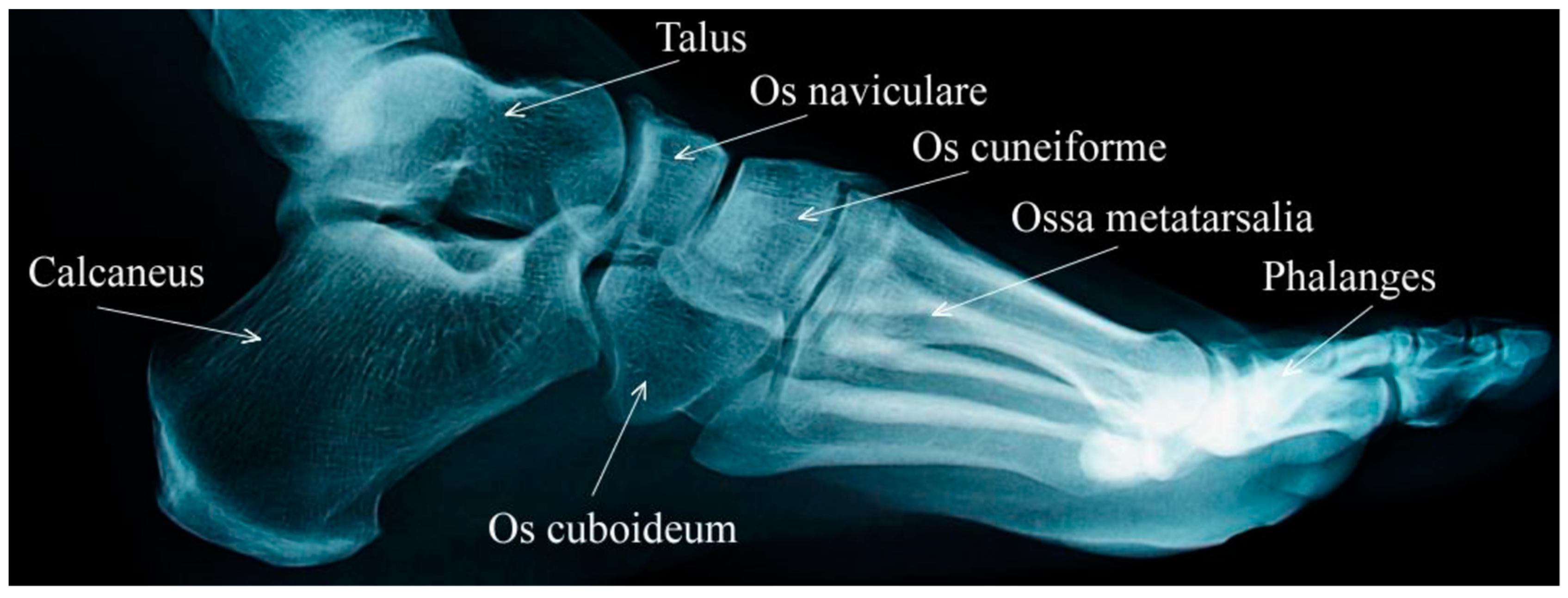
:1. Introduction
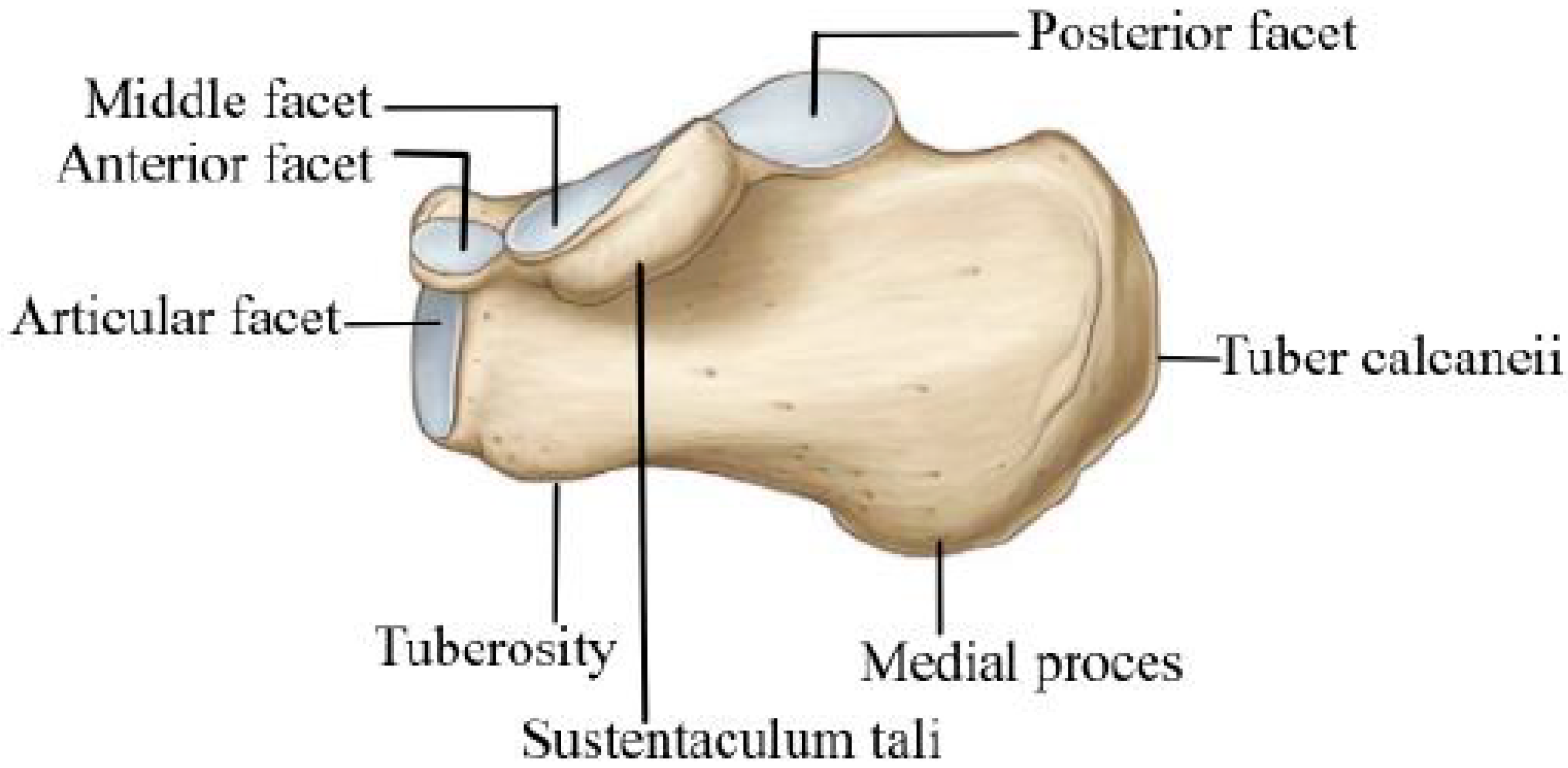
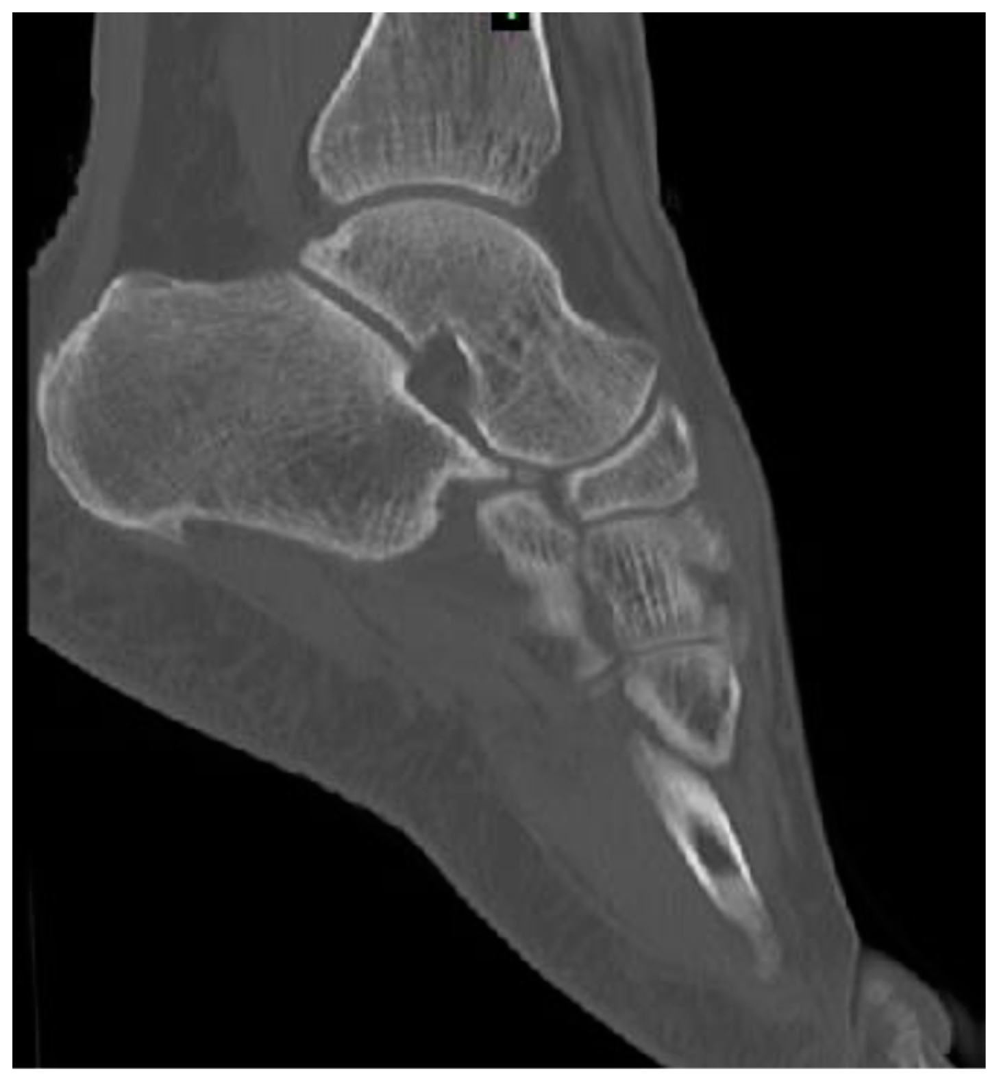
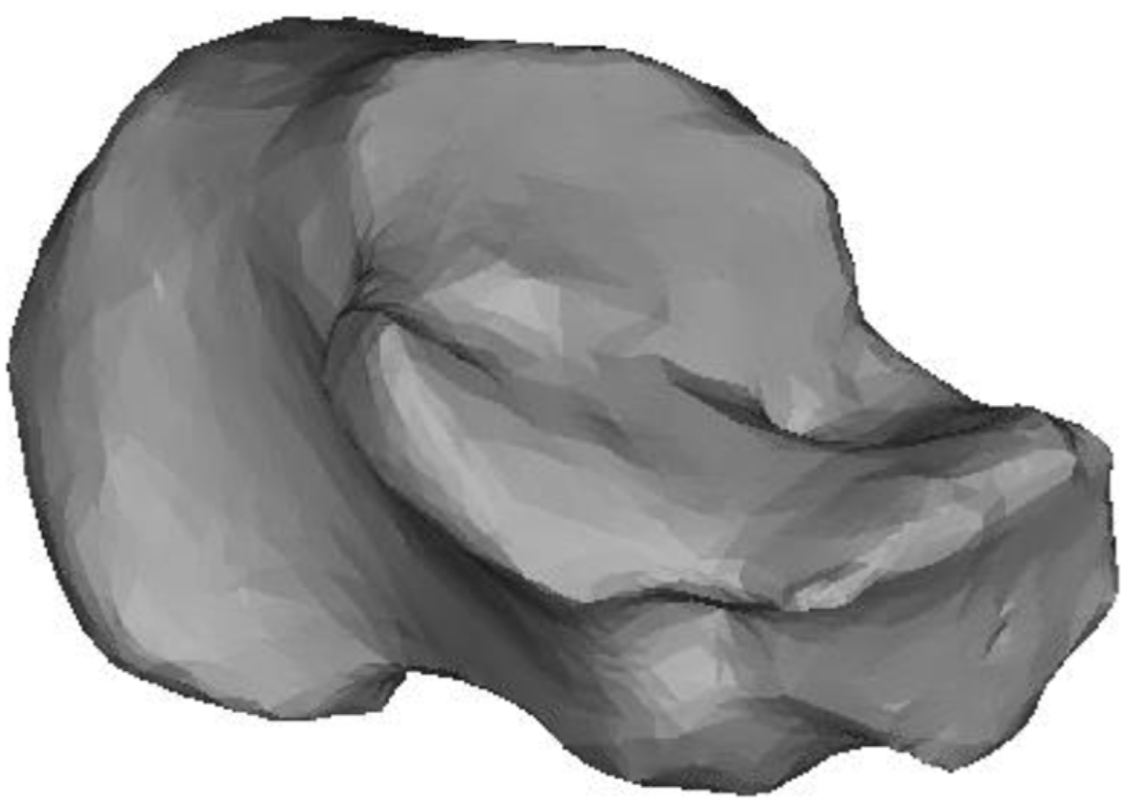
2. Numerical Bone Modelling
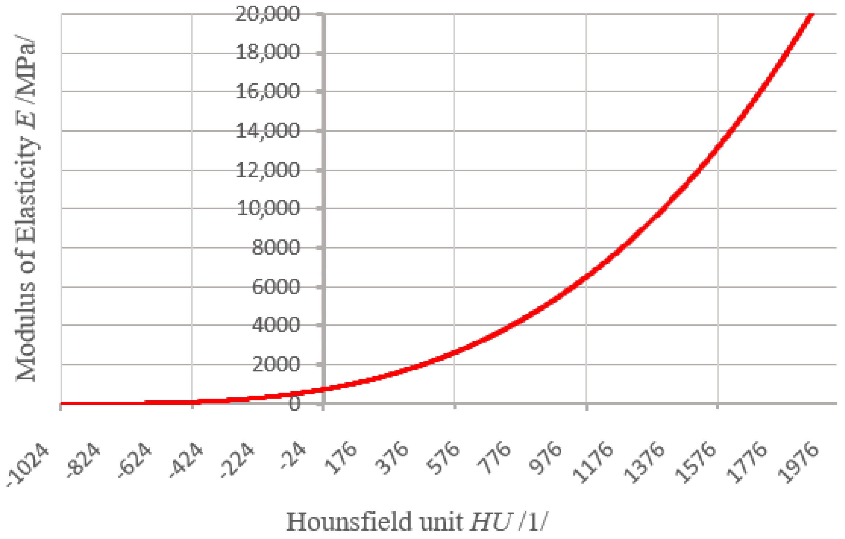
3. Material Properties of the Bone
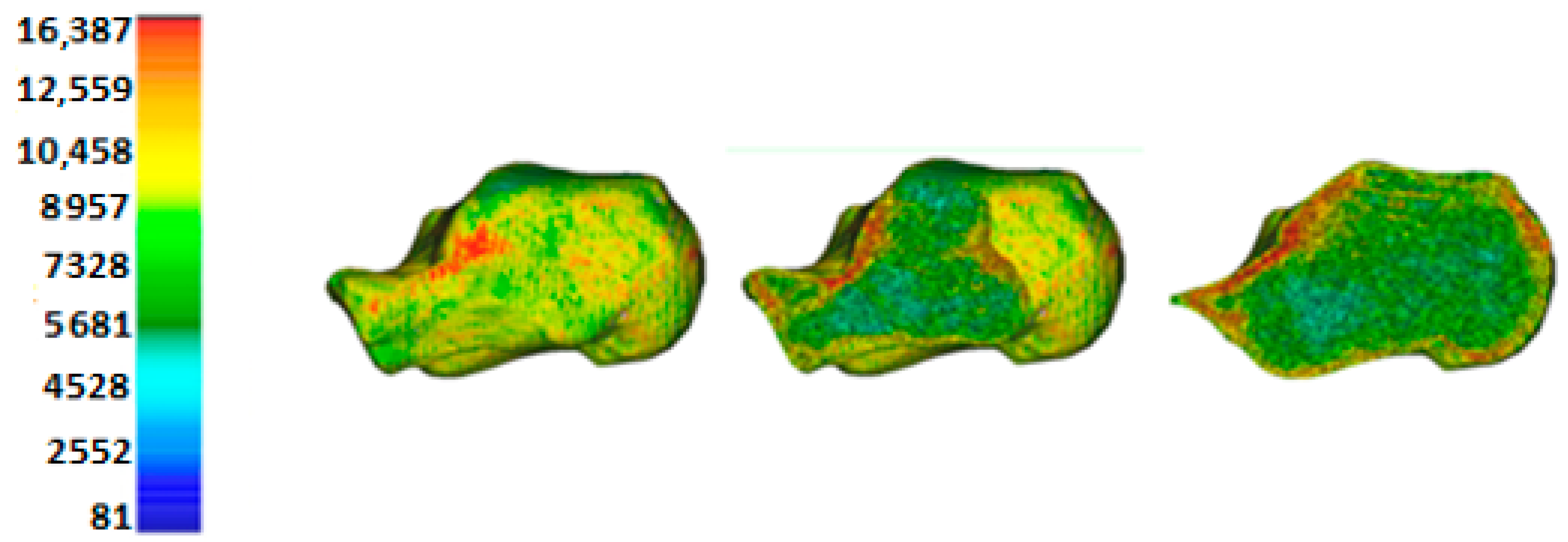
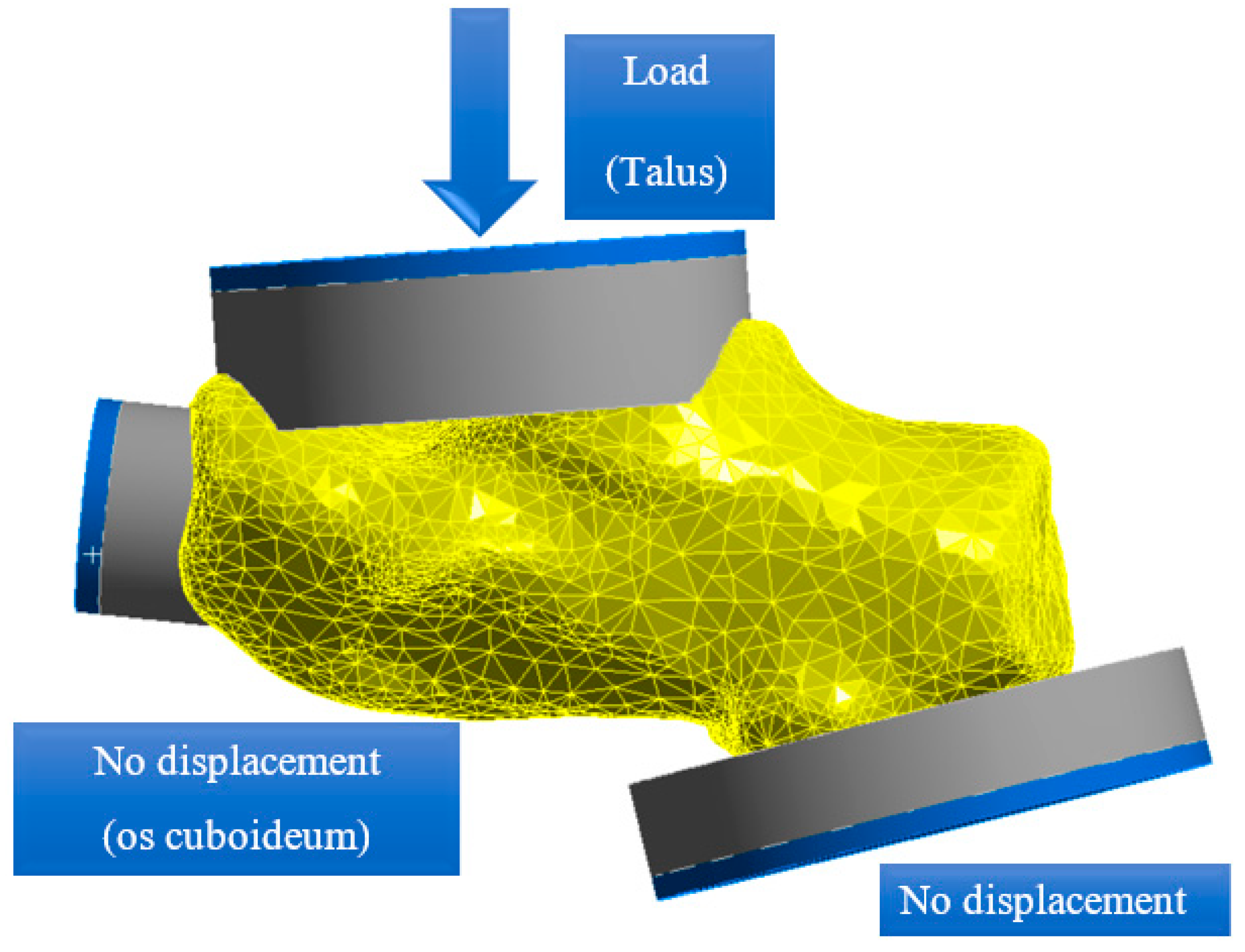
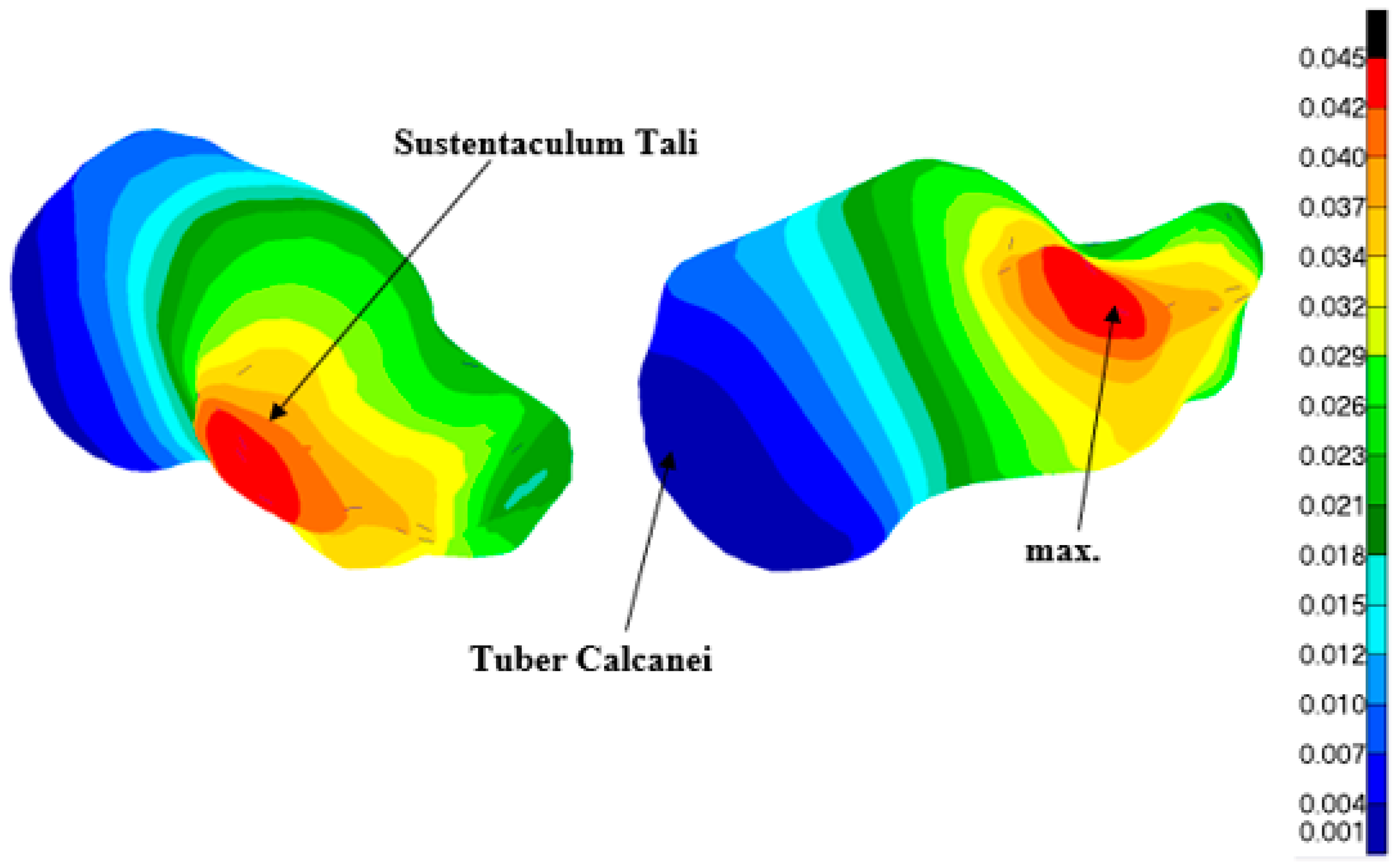
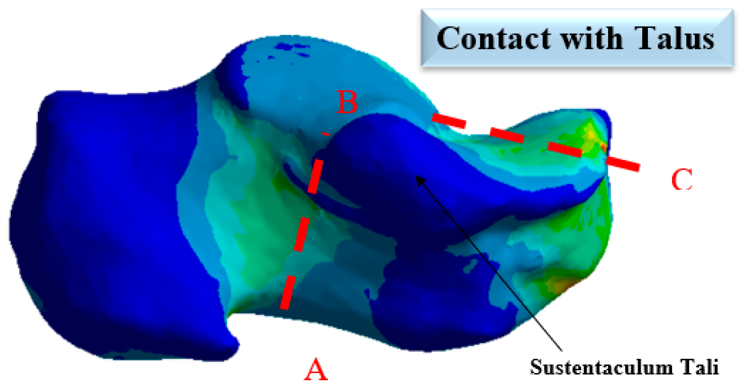
3.1. Strength Analysis of a Healthy Calcaneus without a C-NAIL
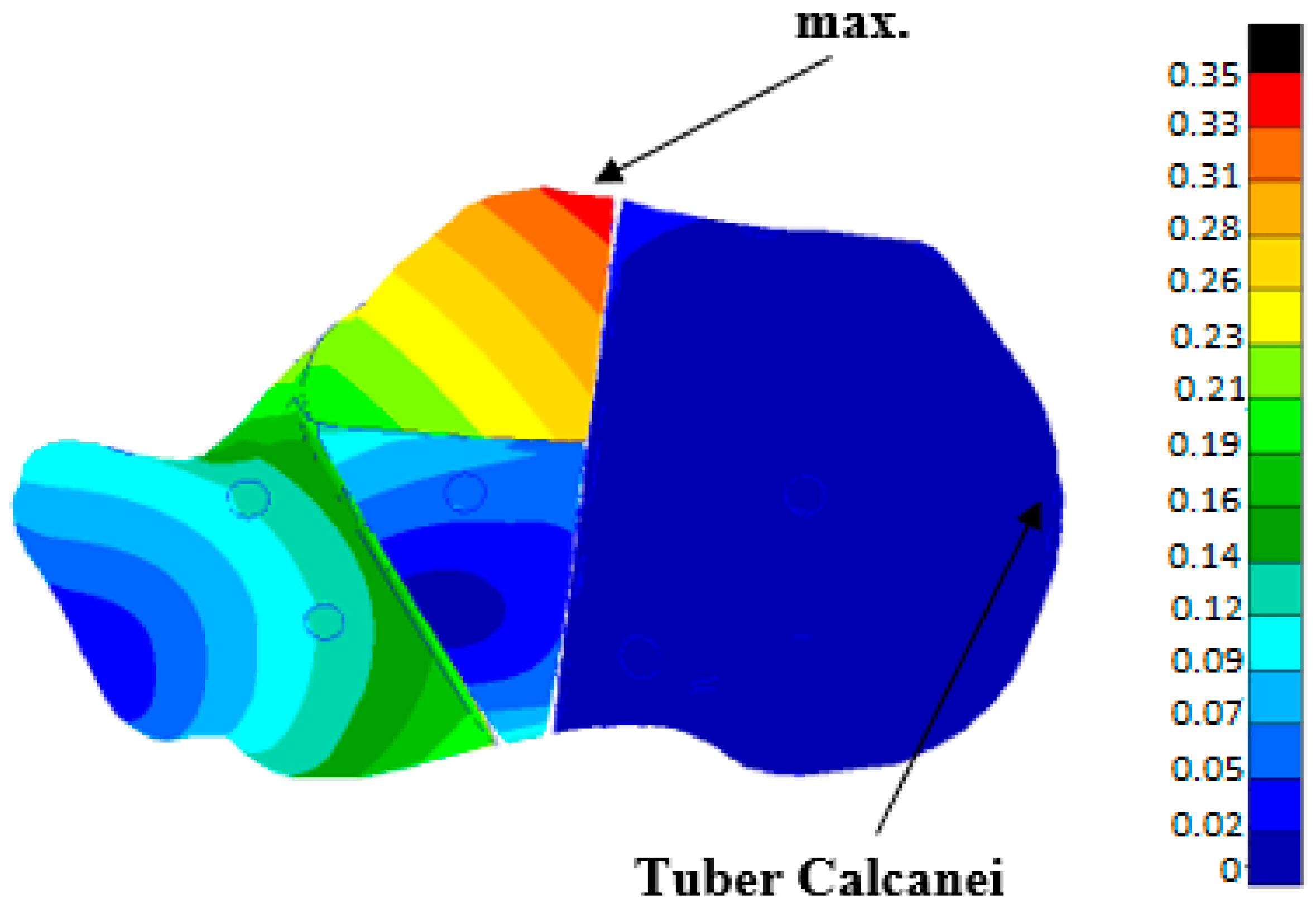
3.2. Strength Analysis of a Healthy Heel Bone without C-NAIL
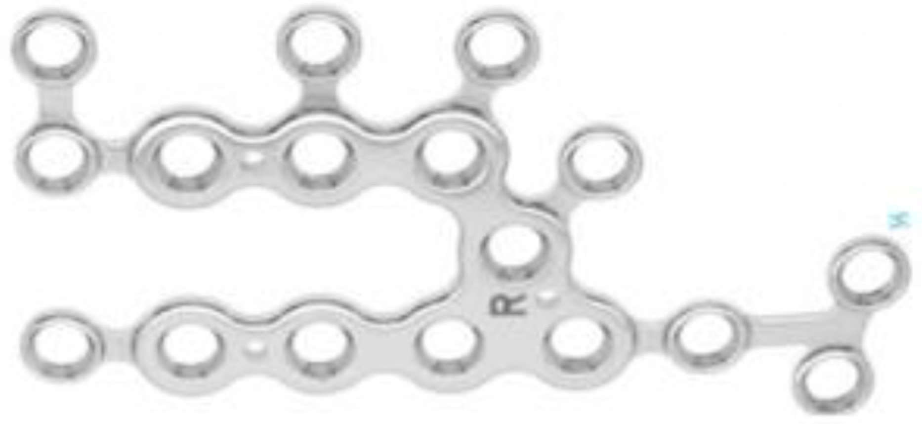
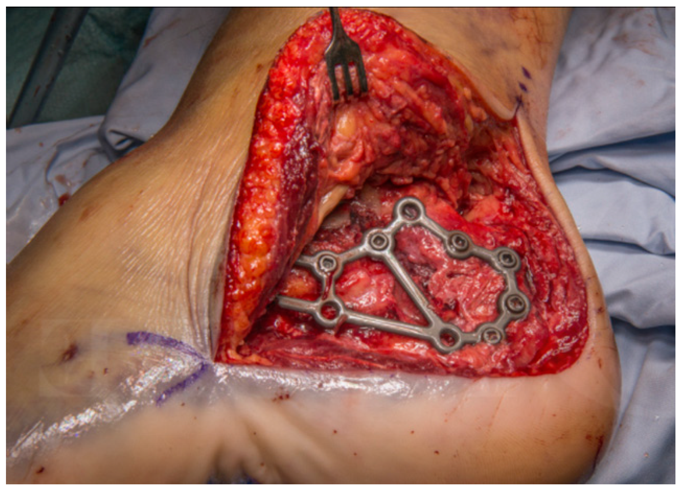
4. Strength Analysis of the Calcaneal Nail C-NAIL in Interaction with the Heel Bone
4.1. Numerical Model
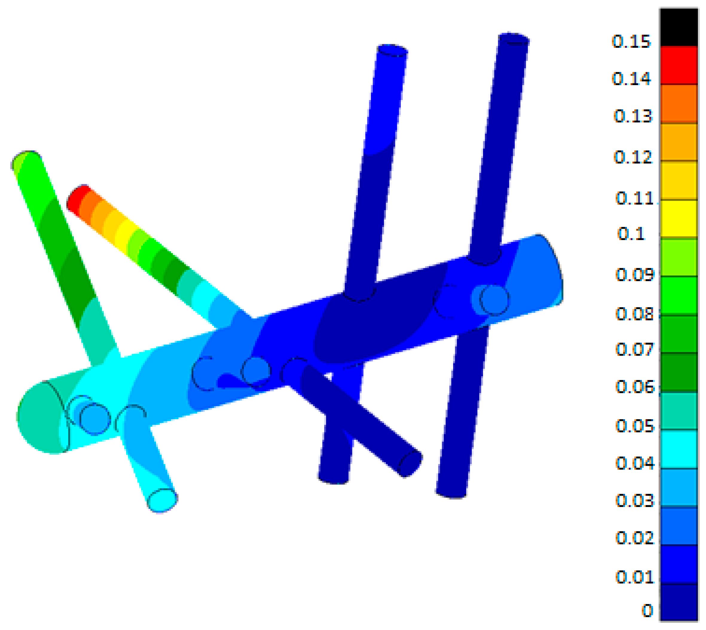
4.2. Calculation Results
5. Conclusions
Author Contributions
Funding
Data Availability Statement
Conflicts of Interest
References
- Logan, B.M.; Singh, D.; Hutchings, R.T. McMinn’s Color Atlas of Foot and Ankle Anatomy; Elsevier Health Sciences: London, UK, 2004; ISBN 9780723431930. [Google Scholar]
- Sejda, F. Biomechanics–Ostheosynthesis of Calcaneal Fractures. Ph.D. Thesis, VSB–Technical University of Ostrava, Ostrava, Czech Republic, 2019. [Google Scholar]
- Pompach, M. Kalkaneální Hřeb C-NAIL, Porovnání Implantátů Pro Osteosyntézu Zlomeniny Patní Kosti. Doctoral Thesis, Univerzita Palackého v Olomouci, Olomouc, Czech Republic, 2016. [Google Scholar]
- Stehlík, J.; Štulík, J. Calcaneal Fracture; Galén Publishing House: Na Popelce, Prague, 2005; ISBN 8072623281. [Google Scholar]
- Normmed-Normmedtrauma. Available online: https://www.normmed.com.tr/normmedtrauma.pdf (accessed on 23 March 2022).
- Medartis–Cases Newsletter F&A Nr1 Cases: Medartis. Available online: https://www.medartis.com/en-us/products/detail/trilock-calcaneus-plates-35/ (accessed on 23 March 2022).
- GPC Meical Ltd.-Calcaneal Locking Plate 3.5mm Left/Right Manufacturer & Supplier|India. Available online: https://www.gpcmedical.com/1217/902/calcaneal-locking-plate-35mm-left-right.html (accessed on 23 March 2022).
- Medin, a.s.: Instruments and Implants for Traumatology [catalog], MEDIN, a.s., 2018, Pages B.2.1-B.2.2. Available online: https://www.medin.cz/media/cache/file/ce/medin-traumatology-catalogue-2018-10-CS-EN_LQ.pdf (accessed on 23 March 2022).
- Hlinka, J.; Dostalova, K.; Dedkova, K.P.; Madeja, R.; Frydrysek, K.; Koutecky, J.; Sova, P.; Douglas, T.E.L. Complex Material and Surface Analysis of Anterolateral Distal Tibial Plate of 1.4441 Steel. Metals 2021, 12, 60. [Google Scholar] [CrossRef]
- Losertova, M.; Štamborská, M.; Lapin, J.; Mareš, V. Comparison of Deformation Behaviour of 316L Stainless Steel and Ti6Al4V Alloy Applied in Traumatology. Matalurgija 2016, 55, 667–670. [Google Scholar]
- ASM, Titanium Ti-6Al 4V. Pompano Beach, 2016. Available online: http://asm.matweb.com/search/SpecificMaterial.asp?bassnum=MTP641 (accessed on 23 March 2022).
- Wikipedia. Available online: https://en.wikipedia.org/wiki/CT_scan (accessed on 23 March 2022).
- Materialise, Mimics Student Edition Course Book. Materialise. Ann Arbor, USA, 2014. Available online: https://www.researchgate.net/file.PostFileLoader.html?id=5686aa597dfbf9d5458b458b&assetKey=AS%3A313124089991168%401451666008906 (accessed on 23 March 2022).
- Yosibash, Z. P-Fems In Biomechanics: Bones And Arteries. Comput. Methods Appl. Mech. Eng. 2012, 249, 169–184. [Google Scholar] [CrossRef]
- Taddei, F.; Schileo, E.; Helgason, B.; Cristofolini, L.; Viceconti, M. The Material Mapping Strategy Influences The Accuracy Of Ct-Based Finite Element Models Of Bones: An Evaluation Against Experimental Measurements. Med. Eng. Phys. 2007, 29, 973–979. [Google Scholar] [CrossRef] [PubMed]
- Kourtis, L.C.; Carter, D.R.; Kesari, H.; Beaupre, G.R. A New Software Tool (Vabatts) To Calculate Bending, Axial, Torsional And Transverse Shear Stresses Within Bone Cross Sections Having Inhomogeneous Material Properties. Comput. Methods Biomech. Biomed. Engin. 2008, 11, 463–476. [Google Scholar] [CrossRef] [PubMed]
- Helgason, B.; Perilli, E.; Schileo, E.; Taddei, F.; Brynjólfsson, S.; Viceconti, M. Mathematical Relationships Between Bone Density And Mechanical Properties: A Literature Review. Clin. Biomech. 2008, 23, 135–146. [Google Scholar] [CrossRef]
- Baca, V.; Horak, Z.; Mikulenka, P.; Dzupa, V. Comparison Of An Inhomogeneous Orthotropic And Isotropic Material Models Used For Fe Analyses. Med. Eng. Phys. 2008, 30, 924–930. [Google Scholar] [CrossRef]
- Khna, S.N.; Warkhedkar, R.M.; Shyam, A.K. Analysis of Hounsfield Unit of Human Bones For Strength Evaluation. Procedia Mater. Sci. 2014, 6, 512–519. [Google Scholar] [CrossRef] [Green Version]
- Richter, M. Polyaxially-Locked Plate Screws Increase Stability of Fracture Fixation in an Experimental Model of Calcaneal Fracture. J. Bone Jt. Surg. 2006, 88, 1257–1263. [Google Scholar] [CrossRef] [Green Version]
- Maxwell, A.; Owens, J.; Gilberts, T.; Tomash, M.; Wayne, J.; Adelaa, R. Biomechanical Performance Of Lateral Versus Dual Locking Plates For Calcaneal Fracture. J. Foot Ankle Surgery. 2015, 54, 830–835. [Google Scholar] [CrossRef] [PubMed]
- Zwipp, H.; Paša, L.; Žilka, L.; Amlang, M.; Rammelt, S.; Pompach, M. Introduction of a New Locking Nail for Treatment of Intraarticular Calcaneal Fractures. J. Orthop. Trauma 2016, 30, e88–e92. [Google Scholar] [CrossRef] [PubMed]
- Devcon Magic Bond™ Epoxy Putty. Online Materials Information Resource-Matweb. Available online: http://www.Matweb.Com/Search/Datasheettext.Aspx?Bassnum (accessed on 23 March 2022).
- Dragosloveanu, S.; Cotor, D.; Dragosloveanu, C.; Stoian, C.; Stoica, I. Preclinical study analysis of massive magnesium alloy graft for calcaneal fractures. Exp. Ther. Med. 2021, 22, 731. [Google Scholar] [CrossRef] [PubMed]
- Sejda, F. Biomechanics-Structural Analysis of C-NAIL. Doctoral Thesis, VŠB–Technical University of Ostrava, Ostrava, Czech Republic, 2014. [Google Scholar]
- Čajka, R.; Labudková, J. Dependence of Deformation of a Plate on the Subsoil in Relation to the Parameters of the 3D Model. Int. J. Mech. 2014, 8, 208–215. [Google Scholar]
- Hrabovský, L.; Fries, J. Transport Performance of a Steeply Situated Belt Conveyor. Energies 2021, 14, 7984. [Google Scholar] [CrossRef]
- Ferfecki, P.; Zapoměl, J. Investigation of Vibration Mitigation of Flexibly Support Rigid Rotors Equipped with Controlled Elements. Procedia Eng. 2012, 48, 135–142. [Google Scholar] [CrossRef] [Green Version]
- Frydrýšek, K.; Šír, M.; Pleva, L.; Szeliga, J.; Stránský, J.; Čepica, D.; Kratochvíl, J.; Koutecký, J.; Madeja, R.; Dědková, K.P.; et al. Stochastic Strength Analyses of Screws for Femoral Neck Fractures. Appl. Sci. 2022, 12, 1015. [Google Scholar] [CrossRef]
- Kompiš, V.; Qin, Q.; Fu, Z.; Chen, C.S.; Droppa, P.; Kelemen, M.; Chen, W. Parallel Computational Models for Composites Reinforced by CNT-Fibres. Eng. Anal. Bound. Elem. 2012, 36, 47–52. [Google Scholar] [CrossRef]
- Kubíček, J.; Tomanec, F.; Černý, M.; Vilímek, D.; Kalová, M.; Oczka, D. Recent Trends, Technical Concepts and Components of Computer-Assisted Orthopedic Surgery Systems: A Comprehensive Review. Sensor 2019, 19, 5199. [Google Scholar] [CrossRef] [Green Version]
- Tvrdá, K. Probability and Sensitivity Analysis of Plate. Appl. Mech. Mater. 2014, 617, 193–196. [Google Scholar] [CrossRef]
- Šotola, M.; Stareczek, D.; Rybanský, D.; Prokop, J.; Maršalek, P. New Design Procedure of Transtibial Prosthesis Bed Stump Using Topological Optimization Method. Symmetry 2020, 12, 1837. [Google Scholar] [CrossRef]


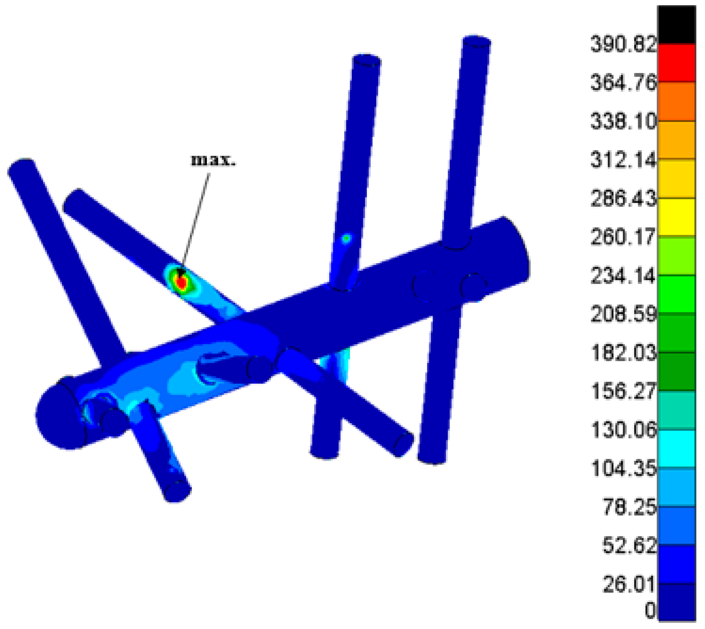
| C-NAIL Displacement/mm/ | Calculated Stress σHMH/MPa/(C-NAIL) | Yield Stress (TiAl4V)/MPa/ |
|---|---|---|
| 0.146 | 390.9 | 912 |
Publisher’s Note: MDPI stays neutral with regard to jurisdictional claims in published maps and institutional affiliations. |
© 2022 by the authors. Licensee MDPI, Basel, Switzerland. This article is an open access article distributed under the terms and conditions of the Creative Commons Attribution (CC BY) license (https://creativecommons.org/licenses/by/4.0/).
Share and Cite
Sejda, F.; Frydrýšek, K.; Pleva, L.; Pompach, M.; Hlinka, J.; Sadílek, M.; Murčinková, Z.; Krpec, P.; Havlíček, M.; Madeja, R.; et al. Numerical Analysis of the Calcaneal Nail C-NAIL. Appl. Sci. 2022, 12, 5265. https://0-doi-org.brum.beds.ac.uk/10.3390/app12105265
Sejda F, Frydrýšek K, Pleva L, Pompach M, Hlinka J, Sadílek M, Murčinková Z, Krpec P, Havlíček M, Madeja R, et al. Numerical Analysis of the Calcaneal Nail C-NAIL. Applied Sciences. 2022; 12(10):5265. https://0-doi-org.brum.beds.ac.uk/10.3390/app12105265
Chicago/Turabian StyleSejda, František, Karel Frydrýšek, Leopold Pleva, Martin Pompach, Josef Hlinka, Marek Sadílek, Zuzana Murčinková, Pavel Krpec, Miroslav Havlíček, Roman Madeja, and et al. 2022. "Numerical Analysis of the Calcaneal Nail C-NAIL" Applied Sciences 12, no. 10: 5265. https://0-doi-org.brum.beds.ac.uk/10.3390/app12105265