
A Convolution-Neural-Network Feedforward Active-Noise-Cancellation System on FPGA for In-Ear Headphone


Department of Electrical Engineering, Pohang University of Science and Technology (POSTECH), Pohang 37673, Korea
*
Author to whom correspondence should be addressed.
Appl. Sci. 2022, 12(11), 5300; https://0-doi-org.brum.beds.ac.uk/10.3390/app12115300
Submission received: 8 April 2022
/
Revised: 18 May 2022
/
Accepted: 23 May 2022
/
Published: 24 May 2022
(This article belongs to the Special Issue Latest Advances in Active Noise Control)
Abstract
:A real-time streaming feedforward active-noise-cancellation (ANC) system for an in-ear headphone was demonstrated in a real application scenario, by implementing a 10-layer dilated convolutional-neural-network (CNN) on a field programmable gate array (FPGA). A 16 × 16 systolic array was used in the FPGA, to speed up the model computation. The system latency was 170.6 s, at the system clock frequency of 120 MHz. The CNN model used 3232 parameters. Due to the large input receptive field, of 327 ms, this work achieved total power reduction, of 14.8 dB and 14.3 dB at the noise incident direction of 0 and 90, respectively, and the noise attenuation bandwidth was 2000 Hz at both angles; all results were superior to those of the conventional FxLMS algorithm.
1. Introduction
Noise cancellation is desirable in many places. An active noise cancellation (ANC) system uses a microphone to sense noise, then uses a speaker to generate complementary waveforms (anti-noise), which are combined with the noise to cancel it by destructive interference [1,2,3,4,5]. Initially, analog ANC was used to generate the anti-noise, with a microphone and a speaker; this method cannot track environmental changes, such as change of the position of the microphone or speaker in the ear canal [6,7,8]. Digital ANC devices use digital signal processor (DSP) chips, to adaptively minimize noise, despite such environmental changes. The devices adaptively adjust coefficients of the finite impulse response (FIR) filter, to minimize noise.
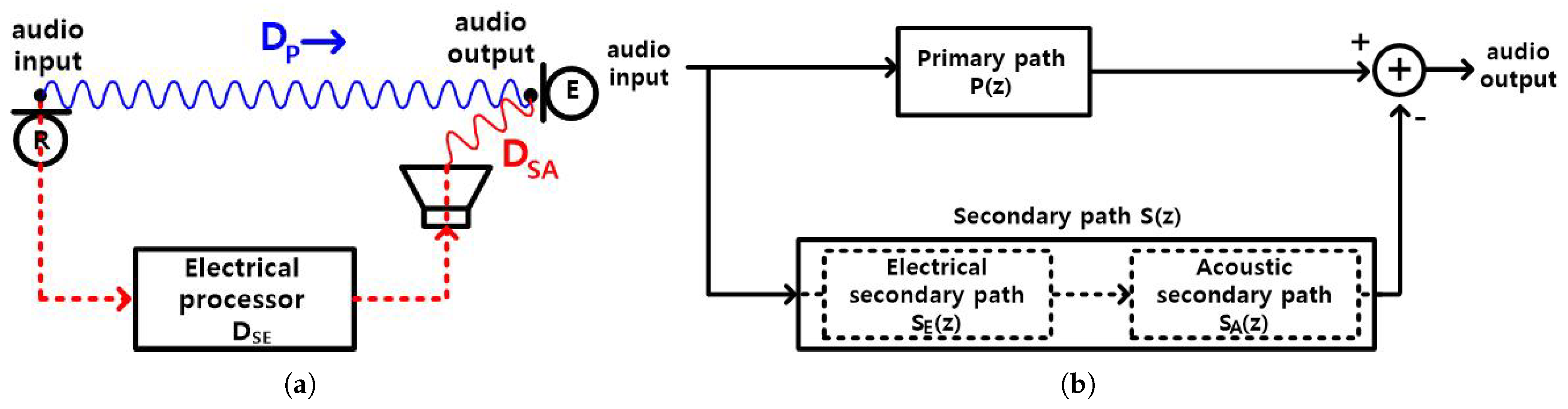
Digital ANCs are classified into feedback [8,9,10,11,12,13,14] and feedforward [14,15,16,17,18,19,20] types. A feedback digital ANC uses a microphone (error) and a speaker. A digital feedforward ANC uses two microphones (reference, error) and a speaker. The frequency range of the ANC operation is limited to ∼600 Hz [12] in the feedback ANC, to maintain loop stability, but is 1500 Hz [15] in the feedforward ANC, for in-ear headphones [15,16,17,18,19]. The requirement for convergence of the adaptive algorithm is tighter in the feedback ANC than in the feedforward ANC [8]. Due to the advantages in frequency range and convergence requirement, feedforward digital ANCs have become widely used. The feedforward ANC has an additional requirement, to satisfy the causality constraint [21,22], i.e., the delay of the electrical processing circuit should be smaller than the primary path delay minus the acoustic secondary path delay . refers to the acoustic propagation delay from the reference microphone input to the error microphone input. The secondary path refers to the combined electrical delay and the acoustic delay (Figure 1a). includes the delays of the reference microphone circuit, the electrical processing circuit, and the speaker driver circuit. includes the speaker delay of electrical-to-acoustic conversion and the acoustic propagation delay from the speaker to the error microphone input. The electrical processing circuit includes an analog-to-digital converter (ADC), FIR filters, and a digital-to-analog converter (DAC); this circuit adds an additional delay, to match the secondary path delay to the primary path delay (Figure 1b). Thus, the causality constraint requires,
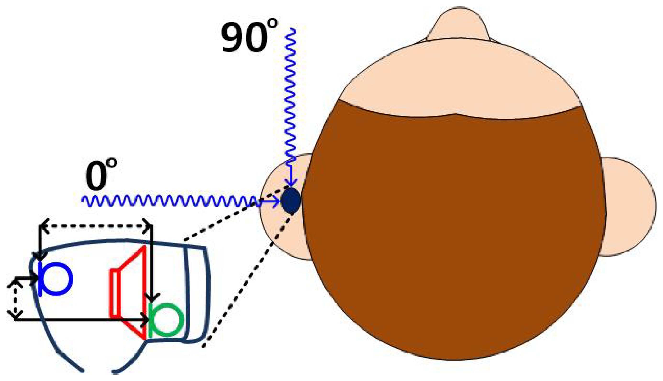
The causality constraint problem does not occur in a large-scale feedforward ANC system, where the distance between speaker and microphone is on a scale of meters and − ≥ ∼3 ms, but in a small-scale feedforward ANC system, such as in-ear headphones [15], the distance between speaker and microphone is tens of millimeters or smaller, and − is tens of microseconds; since this interval is so short, the algorithm thatis used in the electrical processing circuit of the ANC system must react quickly, and, therefore, cannot be too complex, to run within that interval. In in-ear headphones, where two microphones and a speaker are mounted in a small enclosure, the relative arrival times of the sound depend on the direction of the noise source, so the causality constraint, also, depends on this direction (Figure 2). − is smaller when the noise is incident from the front () than from the side (). The electrical processing circuit must finish operation within −, so this causality constraint is harder to meet, when the noise is an incident from the front rather than from the side.
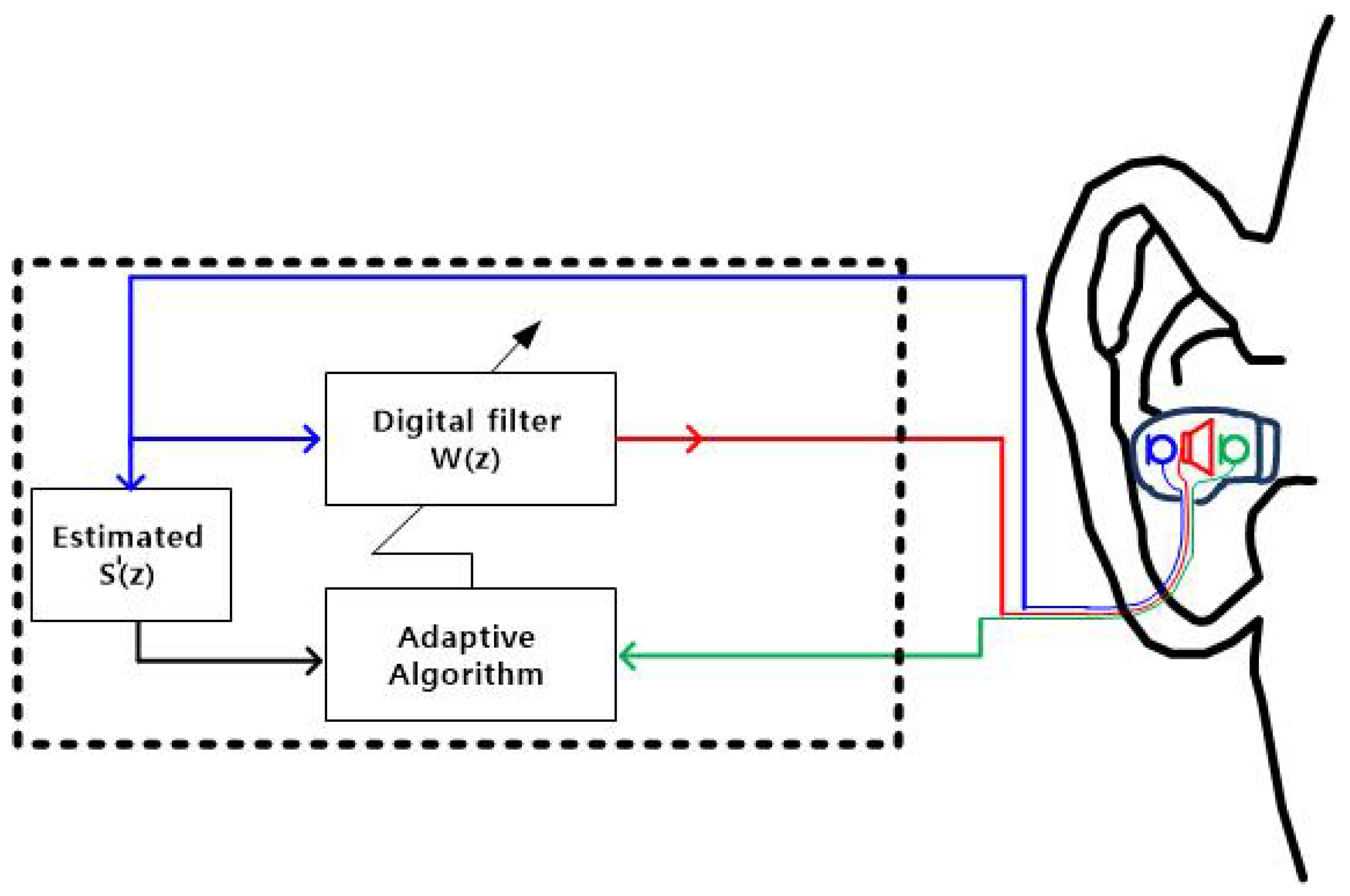
Feedforward ANC that uses the least mean squares (LMS) algorithm suffers from instability in convergence [5]. To solve this problem, a filtered-x LMS (FxLMS) algorithm is used for the feedforward ANC, by including the estimated secondary path model (Figure 3) in the algorithm; this inclusion, also, reduces the convergence time. The digital-filter transfer function is adjusted to minimize the noise inside the ear canal. To mitigate the causality constraint in the feedforward ANC, which uses the FxLMS algorithm, the sampling rate is increased to 96 kHz, but for incidence, the causality constraint is difficult to meet in in-ear headphones; this complication degrades the noise attenuation bandwidth to 850 Hz at incidence, compared to 1500 Hz at incidence. This degradation is considered to be due to the limitation of the FIR filter, with its finite number of 24 taps, to predict future sounds [15].
In this work, a convolutional neural network (CNN) is used, instead of the FxLMS algorithm in the feedforward ANC, to solve the causality constraint. A dilated convolution enables observation of the previous 327 ms of data (=(15,355 samples in the input receptive field)/(sample rate 46,875 S/s)), whereas the FxLMS algorithm [15] observes only the previous 250 s of data (24/96 k); this increase in the observation of previous data increases the noise attenuation bandwidths to 2000 Hz, for both and incidence, and reduces the total power to 14.8 dB at and 14.3 dB at .
2. Architecture of This Work
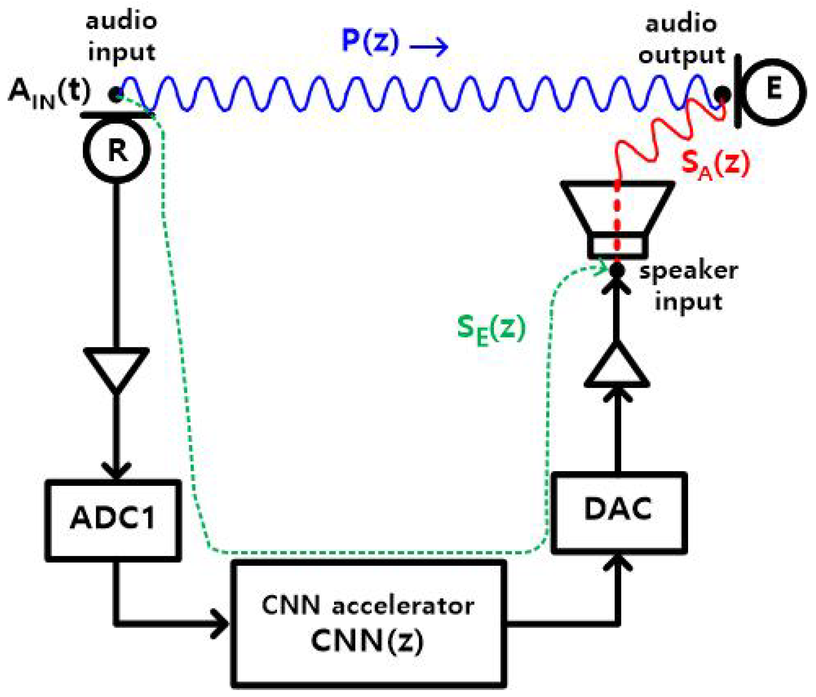
A feedforward ANC that uses a CNN is proposed in this work, to relax the causality constraint; the digital filter of the conventional feedforward ANC (Figure 3) is replaced by a hardware CNN block (Figure 4). The adaptive algorithm is not used in this work. Hence, the transfer function of the CNN block is trained to meet
where P(z) is the transfer function of the primary path, and
is the transfer function of the secondary path. The electrical delay of the CNN block is included in .
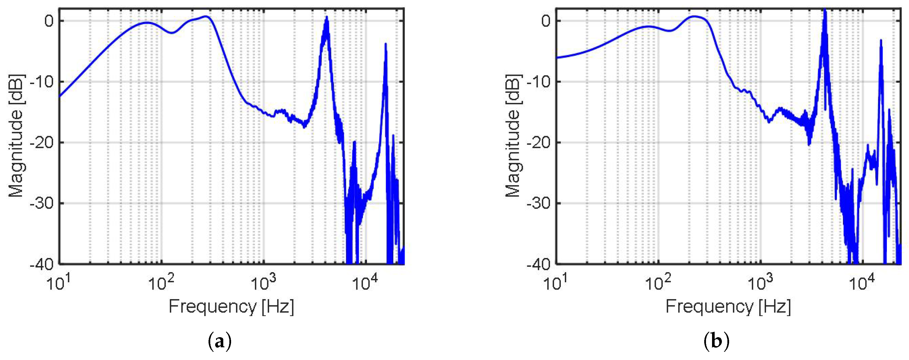
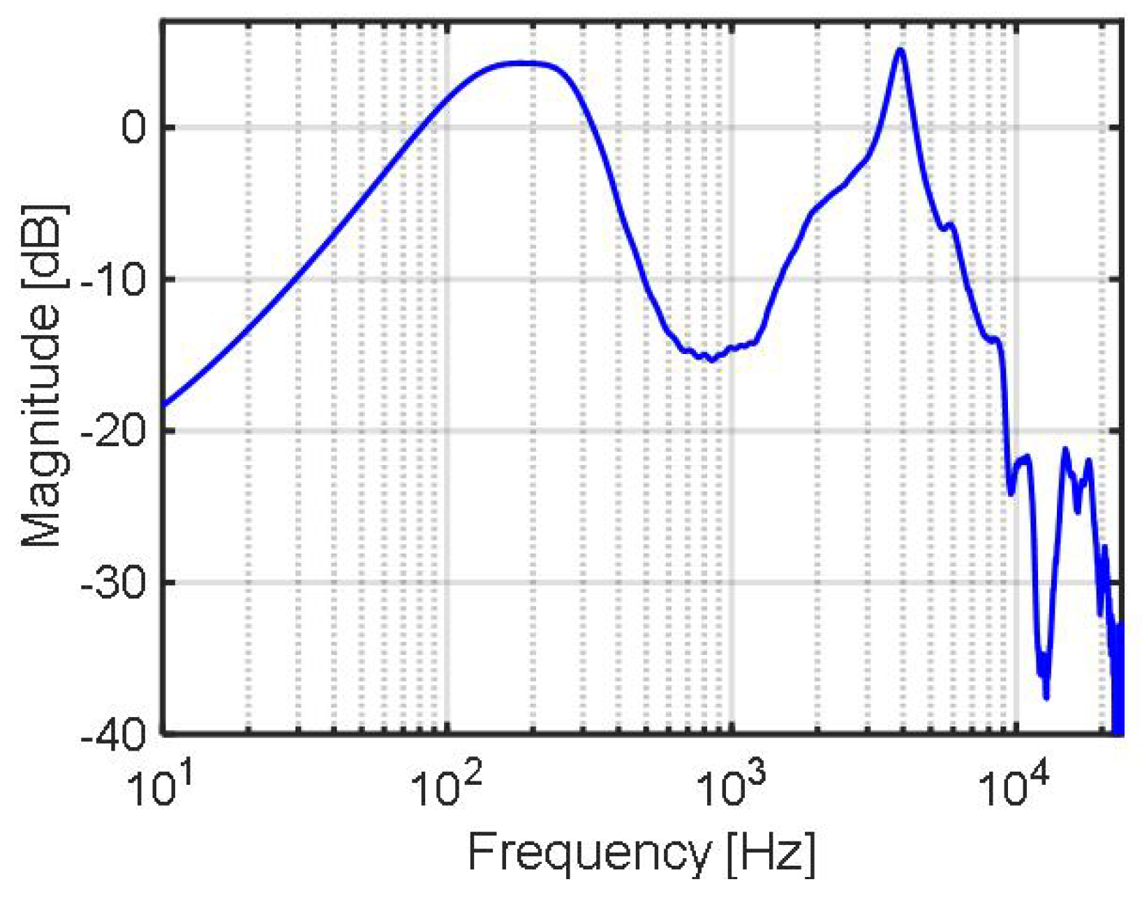
To train the CNN block, the transfer functions (, ) and the time delay must be evaluated a priori. To, accurately, model the inherently nonlinear nature of the primary path, at the noise incidences of and , the impulse response p(t) of the primary path is calculated for the CNN model, which contains nonlinear activation function (ReLU) from the input and output waveforms R(t), (Figure 5a); a broadband white noise was applied to a loudspeaker, which was placed about 60 cm away from an in-ear headphone attached to a human left ear. Similarly, of the acoustic secondary path is calculated from the input and output waveforms (Figure 5b, , ). is 8.0 sample periods in this work (1.5, 5.0, and 1.5 sample periods for ADC1, CNN, and DAC, respectively) (Figure 4). Since the ADC1 is composed of a second-order delta sigma modulator (DSM), followed by a third-order sinc filter, and the processing delay is dominated by the group delay of the sinc filter, the processing delay of ADC1 is 1.5 sample periods. Similarly, the processing delay of DAC is 1.5 sample periods, since it is composed of a third-order interpolation filter, followed by a third-order DSM, and the interpolation filter dominates the delay time. The CNN accelerator takes 5702 clock cycles at a 120 MHz clock (47.5 s, ∼2.2 sample periods), to process an input signal of three samples. The latency of the CNN accelerator is ∼4.2 sample periods, including the waiting delay of the two sample periods spent to collect the three-sample data at the input buffer. Since the DAC accepts input at every sample period, the processing time of the CNN accelerator is five sample periods. The transfer functions of the primary path and the acoustic secondary path are presented in Figure 6 and Figure 7, respectively.
To relax the causality constraint in the proposed feedforward ANC and enable streaming operation, the CNN model should look up as much past data as possible, without the future data. To achieve this goal, a dilated CNN model [23] is used in this work, by increasing the input receptive field to 15,355 samples, without much increase in the latency or the hardware size. The latency of the CNN model is five samples at the sample rate of 46,875 S/s, and the system clock frequency is 120 MHz for the hardware CNN block. The model consists of 10 layers of resnet, followed by a 512-tap FIR filter; the n-th layer includes a dilated 1-D CNN operation (16 kernels, dilation factor of ) and a fully connected (FC) operation (Figure 8). The dilated structure is employed in this work, to predict the future well by increasing the input receptive field. The kernel size of the dilated CNN was chosen to be 16, to maximize the input receptive field and to use a 16 × 16 systolic array hardware for a parallel multiply and accumulation (MAC) operation, while minimizing the number of layers to reduce latency. The total number of parameters used in the proposed model is 3232 = (256 + 16) × 10 + 512.
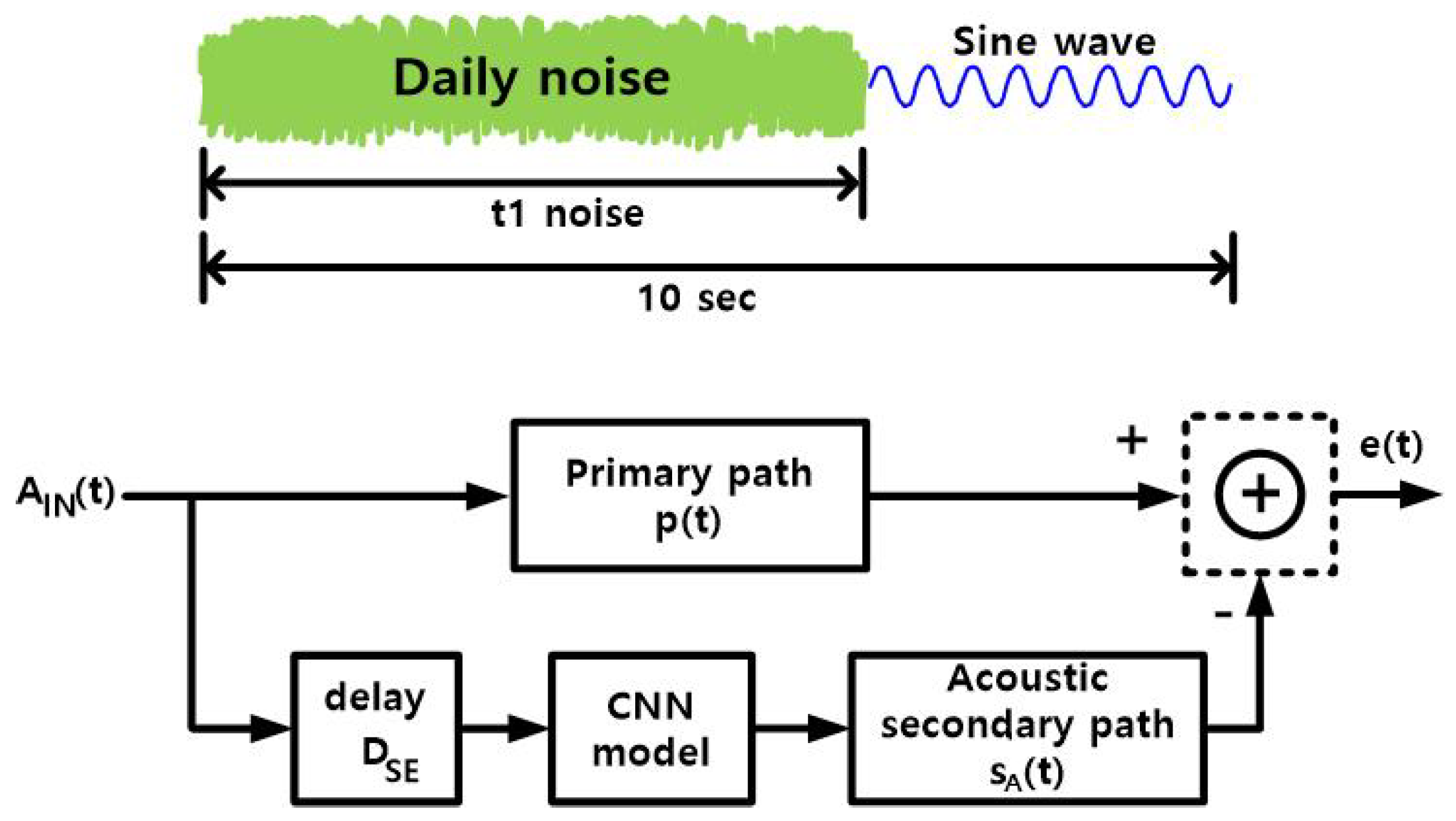
To train the proposed CNN model, the CNN model code was combined with two pre-trained CNN blocks, p(t) and as well as the delay block of (delay of the electrical secondary path, eight sample periods in this work). A 10 s audio input () was used for the training. The model was trained using ambient (“daily”) noise. Sixty hours of such noise (in an airplane, bus, street, cafe, and other places) was collected from YouTube sites and divided into t1-long segments. For training, each input clip consisted of a t1-long daily noise, followed by a single-tone sine wave, where 0 ≤ t1 ≤ 10 s, randomly, and the sine-wave frequency was 0 ≤ f ≤ 2000 Hz, randomly, with an amplitude 0 ≤ A ≤ 1.0, randomly; all random distributions were uniform. The sine wave was added because the daily noise, mostly, has low frequency. For the primary path impulse response p(t) (Figure 9), either the p(t) or the p(t) was selected, randomly, with equal probability for a 10 s input data. A mean absolute error of e(t) (Figure 9) was used as the loss function.
3. Hardware Implementation
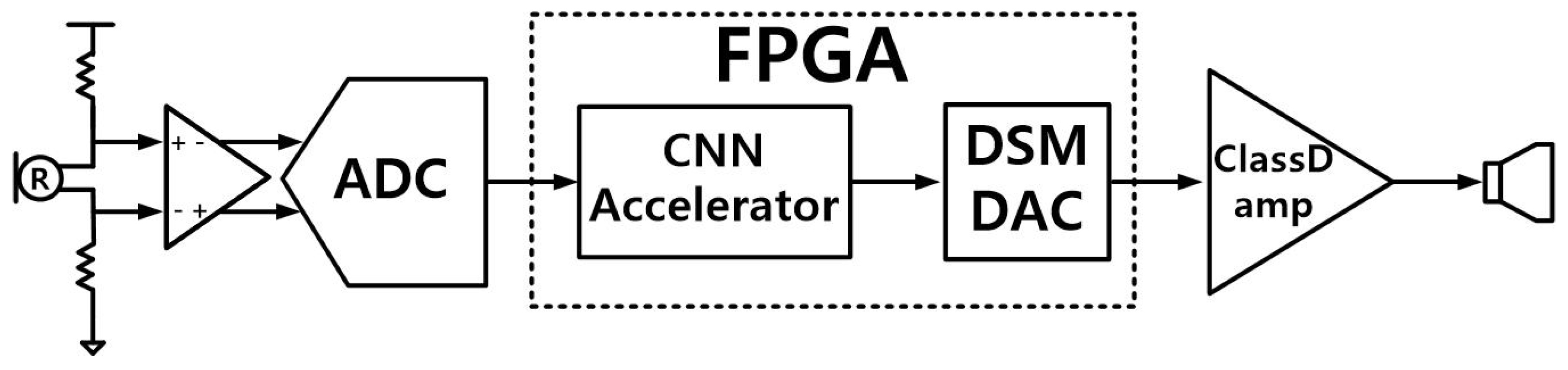
To achieve the real-time streaming operation, the proposed ANC system was implemented using a hardware CNN accelerator (Figure 10); it receives a differential analog signal from the reference microphone R and generates an anti-noise audio signal, through a class-D amplifier and an internal speaker in the in-ear headphone. The analog signal from R is converted to a 16-bit digital signal, at the sample rate of 46,875 S/s; the digital signal is applied to the hardware CNN accelerator, the delta-sigma modulator DAC [24] accepts the 16-bit CNN accelerator output and generates a 1-bit 6-Mbps pulse density modulation signal, which goes through a class-D amplifier, an LC low pass filter (inductance L = 220 H, capacitance C = 470 nF, −3-dB cutoff frequency = 15.7 kHz), and the internal speaker (32 ).
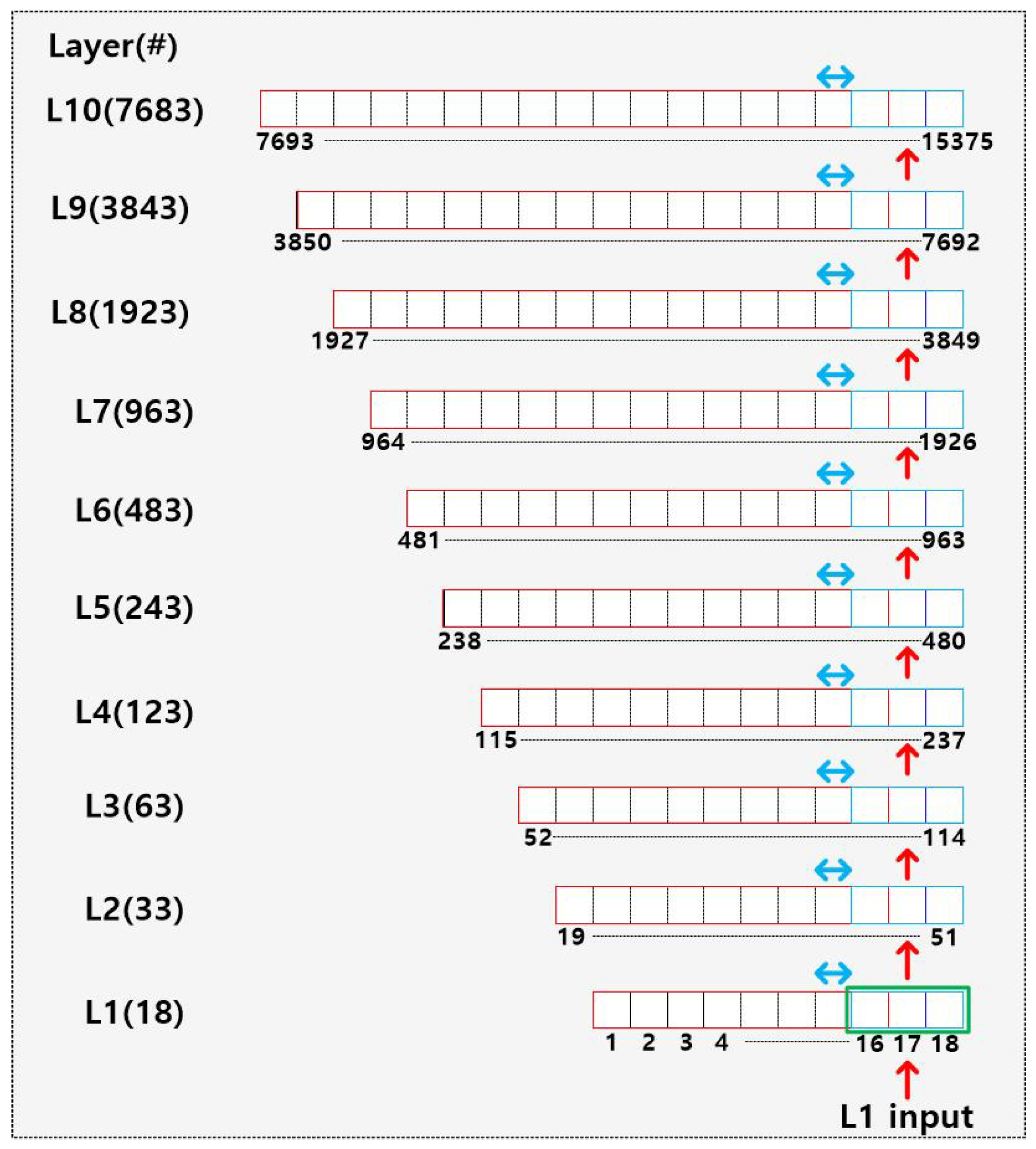
The proposed hardware CNN accelerator was implemented in a field programmable gate array (FPGA), for the inference operation. The operations of the proposed CNN model (Figure 8) are divided into 10 one-layer operations and a 512-tap FIR operation; the one-layer operation is further divided into four steps (dilated 1-D CONV, ReLU, FC, residual/skip add). The number of input samples to the n-th layer (n = 1, 2, 3,…, 10), approximately, doubles as n increases by 1 (Equation (4)):
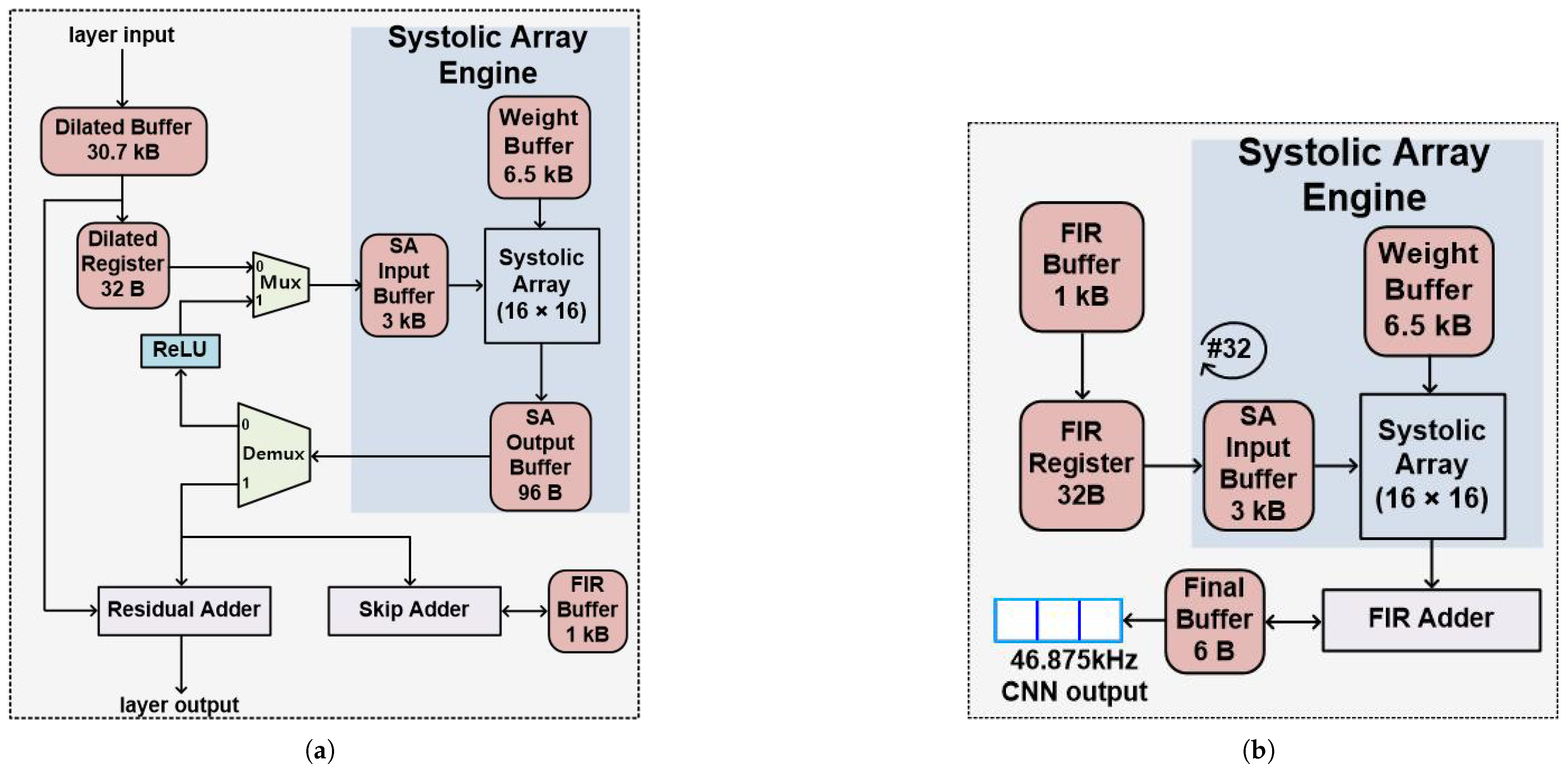
where the kernel size is 16, and the number of time samples is three; three adjacent time samples are taken from the dilated buffer (Figure 11), in a fetch cycle, and are processed, sequentially, in the one-layer operation, to achieve real-time operation, with the processing time of the CNN accelerator (Figure 12a,b) of 47.5 µs (∼2.2 samples), at clock frequency 120 MHz. For real-time streaming operation, the real-time factor should be less than 1. The CNN accelerator takes around the same time, 2.2 sample periods, to process an input unit of one or three samples. The real time factor is 2.2 and 0.74, for the input unit of one and three samples, respectively. Hence, an input unit of three samples is used in this work for the real time operation. The first layer (n = 1) fetches 18 samples L1 [1:18] from the dilated buffer, performs the four step operations, generates an output sample for L1 [1:16], and stores the one-sample output in L2 [49]; the output sample for L1 [2:17] is stored in L2 [50], and the output for L1 [3:18] is stored in L2 [51] (Figure 11). The dilated 1-D CONV operation takes 149 clock cycles to fetch 16 samples from the dilated buffer and perform the dilated 1-D CONV operation, then it stores the 16-bit output to the systolic array (SA) output buffer and repeats this procedure twice. The ReLU operation takes nine clock cycles to move data from the SA output buffer through Demux, RELU, and Mux, to the SA input buffer. The FC operation takes 93 clock cycles to move data from the SA input buffer, through the systolic array, to the SA output buffer. The residual-add and skip-add operations are performed, simultaneously, and take the same time of 14 clock cycles (Figure 12a). After the four-step operations are performed for all 10 layers, the output data of three samples are registered, as the newest data of the 514 samples in the FIR buffer. The FIR filter performs a 512-tap operation on the 512 samples of the FIR buffer, stores one sample output to the final buffer, and repeats this procedure twice (Figure 12b); this process takes 2653 clock cycles (Table 1). The total processing time of the three adjacent input samples is 5702 clock cycles (47.5 s). The clock cycles of every operation in Table 1 were measured by monitoring the state change at the master controller in the Verilog simulations. The system latency is eight samples (170.6 s), including the waiting delay of collecting three samples at the input buffer. The buffers require 41 kB memory, to store the data and the 3232 parameters of the CNN model. The FPGA utilization of the proposed ANC is tabulated in Table 2.
4. Measurement Results
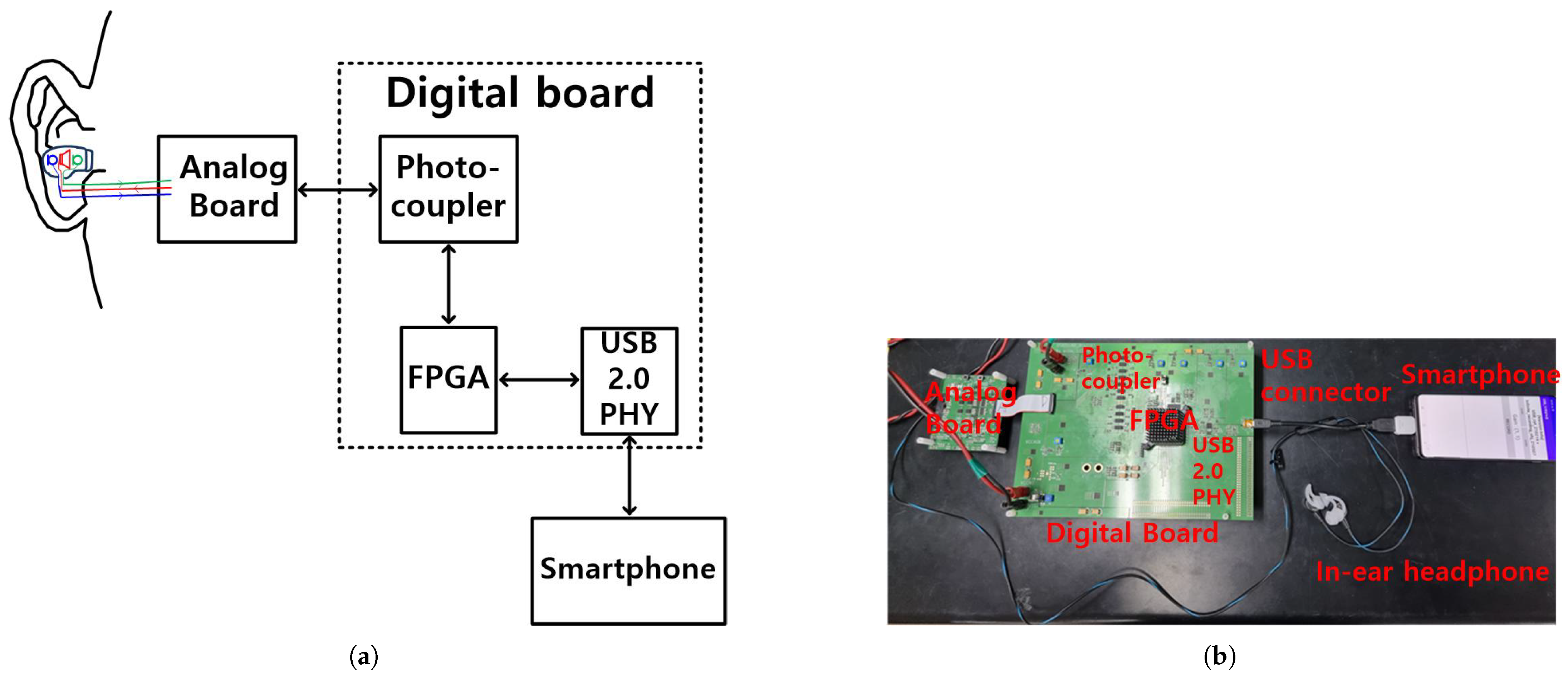
In the measurement setup (Figure 13), the Verilog design of the proposed CNN ANC model (Figure 12) is, first, downloaded from a personal computer to the FPGA, along with the 3232 trained parameters (16-bit floating point numbers). Then, a reset switch starts the ANC operation in the FPGA; it accepts a mono audio input from the reference microphone, performs the CNN ANC operation on the mono audio input, generates an anti-noise signal, and sends it to the speaker of the in-ear headphone, to cancel noise. The FPGA includes a USB 2.0 link, to communicate with a smartphone through a USB 2.0 PHY chip. The smartphone monitors the output data, from the reference and error microphones of the in-ear headphones.
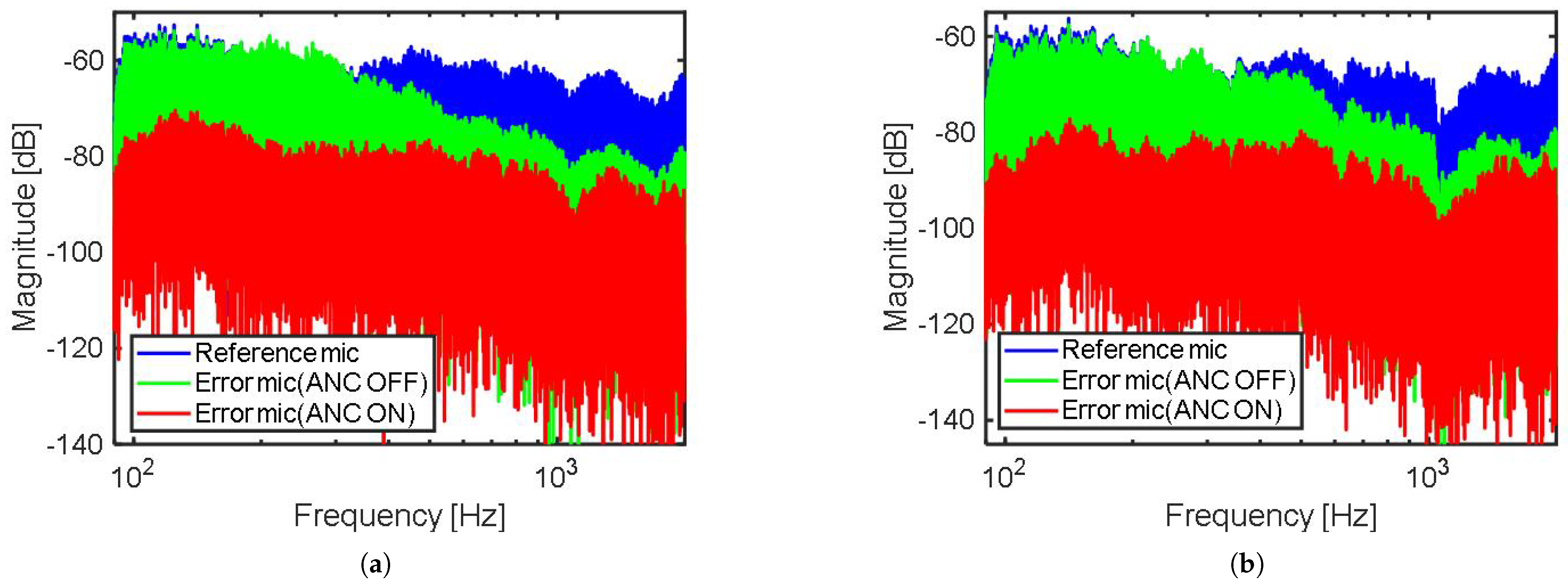
Frequency spectra (Figure 14) of the output data were obtained from the reference and the error microphones, at noise incidence directions of (Figure 14a) and (Figure 14b); a band-limited (100∼2000 Hz) pink noise was applied to a loud speaker. Without the ANC operation, the error microphone output shows a high frequency attenuation, beyond 300 Hz, at both and , due to the mechanical structure of the in-ear headphone. With the ANC operating, the error microphone output demonstrates a large attenuation at low frequency (>20 dB at f < 300 Hz), and total power reduction of 14.8 dB at and 14.3 dB at , compared to the case in which the ANC is not used. With the ANC operating, the attenuation bandwidth was 2000 Hz at both and ; the attenuation bandwidth is defined to be the cross-over frequency of the error microphone spectrum, between the ANC on and off cases.
Since the dilated CNN model of this work predicts the future signal well, by observing a long previous data, it does not need to satisfy the causal constraint; this work observes 327 ms-long previous data, whereas the FxLMS algorithm [15] observes only 250 s-long previous data. The in-ear headphone presented here achieved greater power reduction, attenuation bandwidth, and maximum noise reduction, than previous noise-cancellers that used the FxLMS algorithms (Table 3), and it, especially, achieved an excellent total power reduction of 14.8 dB at and 14.3 dB at , whereas they were 12.2 dB at and 5.6 dB at in [20].
5. Discussion
The conventional real-time ANC, usually, uses the adaptive FxLMS algorithm, to obtain optimum coefficients for the control filter. However, the slow convergence of the adaptive algorithm, perceptibly, limits its reduction of dynamic noise and its overall noise reduction. In addition, the conventional FxLMS algorithm would need to operate at a higher sampling frequency than it does, to avoid violating the causality constraint in ANC headphones. Due to these high processing demands, the fixed-filter method has become the main choice for portable devices or hearables [25,26]. The fixed-filter approach [25] selects a pre-trained control filter, to attenuate the noise instantaneously, and is effective to reduce real-world noise. Therefore, selecting a suitable pre-trained control filter is essential to the ANC system’s noise-reduction effectiveness. The selective fixed-filter ANC method, which uses a CNN, successfully classified noise types in the time domain. The CNN, running in a coprocessor, such as a mobile phone, returns the index of the most-suitable control filter, for each distinct noise type. Subsequently, the controller can update the coefficients of the control filter, according to the filter index [26]. The task of the CNN [26] is to find the optimal fixed filter index, depending on the primary noise types, but the control filter itself is an FIR filter.
This paper successfully demonstrates a real-time streaming hardware feedforward ANC system, for in-ear headphones, by implementing a 10-layer dilated CNN on an FPGA. A 16 × 16 systolic array was used in FPGA, to speed up the model computation. In the offline pre-training stage, the primary and acoustic secondary paths are extracted, using a CNN model. The CNN model consists of 10 layers of resnet, which contain a nonlinear activation function (ReLU) that can effectively model the, inherently, nonlinear nature of the primary path. Then, to train the other CNN model that acts as a control filter, the CNN model code was combined with the above pre-trained CNN blocks, (p(t) and ), as well as the delay of the electrical secondary path. Similarly to [25,26], the CNN model of this work is a fixed filter, in that fixed pre-trained CNN coefficients are used in this work. However, this work uses a non-linear CNN model, while [25,26] uses a linear FIR filter as the processing engine; the FIR filter coefficients of [25,26] are computed by using an algorithm [25] or a CNN model [26].
6. Conclusions
A real-time streaming hardware feedforward ANC system was implemented in an FPGA, for in-ear headphones, by using a deep-learning model. The effectiveness of the conventional FxLMS algorithm degrades in in-ear headphones because the electrical-processing delay is long, compared to the short acoustic propagation delay, due to the small size of the headphones. The system presented here uses an enhanced prediction of future data, by using a 10-layer dilated CNN model, with the input receptive field of 327 ms, and, as a result, achieves better noise-power reduction than the FxLMS algorithm. The CNN model has 3232 trained parameters (16-bit floating point). The feedforward ANC consists of an internal speaker and two microphones, the external reference microphone and the internal error microphone; an electrical processing circuit accepts the output signal of the reference microphone, generates an anti-noise signal, and sends it to the internal speaker, to cancel noise. To maintain numerical stability for training, the transfer functions of the primary path and the secondary path are added to the CNN model; the primary path refers to the acoustic propagation path, from the reference microphone input to the error microphone input, and the secondary path includes the sum of the electrical signal path of the electrical processing circuit and the acoustic propagation path, from the internal speaker to the reference microphone input. The transfer function of acoustic propagation paths changes with the change of the incident direction of noise. A 60 h sample of daily noise, acquired from YouTube, and a single-tone sine wave with frequency <2000 Hz are combined to form the input data for the training of the CNN model; the incident direction of the input data was chosen to be or , with equal probability. The CNN model was implemented in an FPGA that had a system clock frequency of 120 MHz; a 16 × 16 systolic array was used for speedup. The operation of the feedforward ANC system was demonstrated, successfully, in a real application scenario, by combining the FPGA, an analog board, and an in-ear headphone. The measured system latency was 170.6 s. For a band-limited pink noise input (100∼2000 Hz), the noise-power reduction was measured to be 14.8 dB and 14.3 dB at and incident direction, respectively, and the attenuation bandwidth was 2000 Hz, at both incident directions.
Author Contributions
Conceptualization, Y.-J.J. and H.-J.P.; hardware design, Y.-J.J. (analog/digital whole design), J.P. (16 × 16 systolic array), and W.-C.L. (USB 2.0 link); software, Y.-J.J.; smartphone program, W.-C.L.; project administration (working together during the whole editorial process of the manuscript), Y.-J.J. and H.-J.P. All authors have read and agreed to the published version of the manuscript.
Funding
This work was supported in part by Samsung Electronics Co., Ltd. (IO201209-07912-01); in part by Basic Science Research Program through the National Research Foundation of Korea funded by the Ministry of Education (2019R1A5A1027055); and in part by Basic Science Research Program through the National Research Foundation of Korea funded by the Ministry of Education (2022R1A2C2003451).
Institutional Review Board Statement
Not applicable.
Informed Consent Statement
Not applicable.
Data Availability Statement
Not applicable.
Conflicts of Interest
The authors declare no conflict of interest.
References
- Kuo, S.M.; Morgan, D.R. Active Noise Control: A Tutorial Review. Proc. IEEE 1999, 87, 943–973. [Google Scholar] [CrossRef] [Green Version]
- Kuo, S.M.; Morgan, D.R. Active Noise Control Systems: Algorithms and DSP implementations; John Wiley & Sons: New York, NY, USA, 1996. [Google Scholar]
- Elliott, S.J. Signal Processing of Active Noise Control; Academic Press: London, UK, 2001. [Google Scholar]
- Miljković, D. Active noise control: From analog to digital-Last 80 years. In Proceedings of the 2016 39th International Convention on Information and Communication Technology, Electronics and Microelectronics (MIPRO), Opatija, Croatia, 30 May–3 June 2016. [Google Scholar] [CrossRef]
- Kajikawa, Y.; Gan, W.-S.; Kuo, S.M. Recent advances on active noise control: Open issues and innovative applications. APSIPA Trans. Signal Inf. Process. 2012, 1, E3. [Google Scholar] [CrossRef] [Green Version]
- Gan, W.-S.; Kuo, S.M. An integrated audio and active noise control headset. IEEE Trans. Consum. Electron. 2002, 48, 242–247. [Google Scholar] [CrossRef]
- Gan, W.-S.; Mitra, S.; Kuo, S.M. Adaptive feedback active noise control headset: Implementation, evaluation and its extensions. IEEE Trans. Consum. Electron. 2005, 51, 975–982. [Google Scholar] [CrossRef]
- Song, Y.; Gong, Y.; Kuo, S.M. A robust hybrid feedback active noise cancellation headset. IEEE Trans. Speech Audio Process. 2005, 13, 607–617. [Google Scholar] [CrossRef] [Green Version]
- Kuo, S.M.; Chuang, H.; Mallela, P.P. Integrated automotive signal processing and audio system. IEEE Trans. Consum. Electron. 1993, 39, 522–532. [Google Scholar] [CrossRef]
- Kuo, S.M.; Mitra, S.; Gan, W.-S. Active Noise Control System for Headphone Applications. IEEE Trans. Control Syst. Technol. 2006, 14, 331–335. [Google Scholar] [CrossRef]
- Chang, C.-Y.; Li, S.-T. Active Noise Control in Headsets by using a Low-Cost Microcontroller. IEEE Trans. Ind. Electron. 2011, 58, 1936–1942. [Google Scholar] [CrossRef]
- Vu, H.-S.; Chen, K.-H. A 1.4 mW low-power feedback FxLMS ANC VLSI design for in-ear Headphones. In Proceedings of the 2016 International Symposium on VLSI Design, Automation and Test (VLSI-DAT), Hsinchu, Taiwan, 25–27 April 2016. [Google Scholar] [CrossRef]
- Kuo, S.M.; Chen, Y.-R.; Chang, C.-Y.; Lai, C.-W. Development and Evaluation of Light-Weight Active Noise Cancellation Earphones. Appl. Sci. 2018, 8, 1178. [Google Scholar] [CrossRef] [Green Version]
- Chang, C.-Y.; Siswanto, A.; Ho, C.-Y.; Yeh, T.-K.; Chen, Y.-R.; Kuo, S.M. Listening in a Noisy Environment: Integration of active noise control in audio products. IEEE Consum. Electron. Mag. 2016, 5, 34–43. [Google Scholar] [CrossRef]
- Vu, H.-S.; Chen, K.-H. A Low-Power Broad-Bandwidth Noise Cancellation VLSI Circuit Design for In-Ear Headphones. IEEE Trans. Very Large Scale Integr. (VLSI) Syst. 2016, 24, 2013–2025. [Google Scholar] [CrossRef]
- Vu, H.-S.; Chen, K.-H.; Sun, S.-F.; Fong, T.-M.; Hsu, C.-W.; Wang, L. A Power-Efficient Circuit Design of Feed-Forward FxLMS Active Noise Cancellation for In-ear Headphones. In Proceedings of the 2015 International Symposium on VLSI Design, Automation and Test (VLSI-DAT), Hsinchu, Taiwan, 27–29 April 2015. [Google Scholar] [CrossRef]
- Vu, H.-S.; Chen, K.-H.; Sun, S.-F.; Fong, T.-M.; Hsu, C.-W.; Wang, L. A 6.42 mW low-power feedforward FxLMS ANC VLSI design for in-ear headphones. In Proceedings of the 2015 IEEE International Symposium on Circuits and Systems (ISCAS), Lisbon, Portugal, 24–27 May 2015. [Google Scholar] [CrossRef]
- Vu, H.-S.; Chen, K.-H.; Fong, T.-M. Active noise control for in-ear headphones: Implementation and evaluation. In Proceedings of the 2015 International Conference on Consumer Electronics-Taiwan, Taipei, Taiwan, 6–8 June 2015. [Google Scholar] [CrossRef]
- Huang, C.-R.; Chang, C.-Y.; Kuo, S.M. Directional Dependency for Feedforward Active Noise Control Systems with In-Ear Headphones. In Proceedings of the 2021 International Conference on System Science and Engineering(ICSSE), Ho Chi Minh City, Vietnam, 26–28 August 2021. [Google Scholar] [CrossRef]
- Shi, D.; Shi, C.; Gan, W.-S. A Systolic FxLMS Structure for Implementation of Feedforward Active Noise Control on FPGA. In Proceedings of the 2016 Asia-Pacific Signal and Information Processing Association Annual Summit and Conference (APSIPA), Jeju, Korea, 13–16 December 2016. [Google Scholar] [CrossRef]
- Zhang, L.; Qiu, X. Causality study on a feedforward active noise control headset with different noise coming directions in free field. Appl. Acoust. 2014, 80, 36–44. [Google Scholar] [CrossRef]
- Kong, X.; Kuo, S.M. Study of causality constraint on feedforward active noise control systems. IEEE Trans. Circuits Syst. II Analog Digit. Signal Process. 1999, 46, 183–186. [Google Scholar] [CrossRef]
- Oord, A.; Dieleman, S.; Zen, H.; Simonyan, K.; Vinyals, O.; Graves, A.; Kalchbrenner, N.; Senior, A.; Kavukcuoglu, K. Wavenet: A Generative Model for Raw Audio. arXiv 2016, arXiv:1609.03499. [Google Scholar] [CrossRef]
- Schreier, R.; Temes, G.C. Understanding Delta-Sigma Data Converters; Wiley-IEEE Press: Hoboken, NJ, USA, 2017. [Google Scholar]
- Shi, D.; Gan, W.-S.; Lam, B.; Wen, S. Feedforward Selective Fixed-Filter Active Noise Control: Algorithm and Implementation. IEEE/ACM Trans. Audio Speech Lang. Process. 2020, 28, 1479–1492. [Google Scholar] [CrossRef]
- Shi, D.; Lam, B.; Ooi, K.; Shen, X.; Gan, W.-S. Selective fixed-filter active noise control based on convolutional neural network. Signal Process. 2022, 190, 108317. [Google Scholar] [CrossRef]
Figure 1.
Feedforward ANC (a) time delay and (b) block diagram. Blue: Primary path, Red: Secondary path.
Figure 1.
Feedforward ANC (a) time delay and (b) block diagram. Blue: Primary path, Red: Secondary path.

Figure 2.
Dependency of causality constraint on the direction of noise source in in-ear headphones. Blue: reference microphone, Green: error microphone, Red: speaker.
Figure 2.
Dependency of causality constraint on the direction of noise source in in-ear headphones. Blue: reference microphone, Green: error microphone, Red: speaker.

Figure 3.
Conventional feedforward ANC system, using the FxLMS algorithm for an in-ear headphone. Estimated : secondary path model. Blue: reference microphone, Green: error microphone, Red: speaker.
Figure 3.
Conventional feedforward ANC system, using the FxLMS algorithm for an in-ear headphone. Estimated : secondary path model. Blue: reference microphone, Green: error microphone, Red: speaker.

Figure 4.
Proposed feedforward ANC of this work, using a CNN accelerator in FPGA. Blue: Primary path, Green: Electrical secondary path, Red: Acoustic secodnary path.
Figure 4.
Proposed feedforward ANC of this work, using a CNN accelerator in FPGA. Blue: Primary path, Green: Electrical secondary path, Red: Acoustic secodnary path.

Figure 5.
(a) Measurement of the primary path , (b) measurement of the acoustic secondary path . Blue: Primary path, Red: Acoustic secondary path.
Figure 5.
(a) Measurement of the primary path , (b) measurement of the acoustic secondary path . Blue: Primary path, Red: Acoustic secondary path.

Figure 6.
Transfer function of the primary path , with the noise incidence angle of (a) , (b) .

Figure 7.
Transfer function of the acoustic secondary path .

Figure 8.
Propsed CNN model.

Figure 9.
Training scheme of the proposed CNN model.

Figure 10.
The proposed ANC system, using the hardware CNN accelerator.

Figure 11.
Dilated buffer address used for the dilated 1-D convolution.

Figure 12.
Proposed CNN model accelerator implementation (a) layer operation and (b) 512-tap FIR filter operation.
Figure 12.
Proposed CNN model accelerator implementation (a) layer operation and (b) 512-tap FIR filter operation.

Figure 13.
Measurement setup (a) block diagram and (b) photo.

Figure 14.
Frequency spectrum of the error microphone output in the in-ear headphone for the ANC of this work. Blue: reference mic, green: error mic (ANC OFF), red: error mic (ANC ON). (a) Noise incident from direction, (b) noise incident from direction.
Figure 14.
Frequency spectrum of the error microphone output in the in-ear headphone for the ANC of this work. Blue: reference mic, green: error mic (ANC OFF), red: error mic (ANC ON). (a) Noise incident from direction, (b) noise incident from direction.


Table 1.
Operation cycles of the proposed CNN model, to process three samples.
| Operation | Measured Cycles | Measured Time (s) | |
|---|---|---|---|
| 1 | Dilated 1-D CONV | 1490 | 12.4 |
| 2 | ReLU | 90 | 0.7 |
| 3 | FC | 930 | 7.8 |
| 4 | Residual/skip add | 140 | 1.2 |
| 5 | 512-tap FIR | 2653 | 22.1 |
| - | Others | 399 | 3.3 |
| - | Total | 5702 | 47.5 |
Table 2.
FPGA utilization of the proposed ANC system.
| FF | LUT | DSP | BRAM | |
|---|---|---|---|---|
| Proposed CNN Model | 68,811 | 94,011 | 261 | 20 |
Publisher’s Note: MDPI stays neutral with regard to jurisdictional claims in published maps and institutional affiliations. |
© 2022 by the authors. Licensee MDPI, Basel, Switzerland. This article is an open access article distributed under the terms and conditions of the Creative Commons Attribution (CC BY) license (https://creativecommons.org/licenses/by/4.0/).
Share and Cite
MDPI and ACS Style
Jang, Y.-J.; Park, J.; Lee, W.-C.; Park, H.-J. A Convolution-Neural-Network Feedforward Active-Noise-Cancellation System on FPGA for In-Ear Headphone. Appl. Sci. 2022, 12, 5300. https://0-doi-org.brum.beds.ac.uk/10.3390/app12115300
AMA Style
Jang Y-J, Park J, Lee W-C, Park H-J. A Convolution-Neural-Network Feedforward Active-Noise-Cancellation System on FPGA for In-Ear Headphone. Applied Sciences. 2022; 12(11):5300. https://0-doi-org.brum.beds.ac.uk/10.3390/app12115300
Chicago/Turabian StyleJang, Young-Jae, Jaehyun Park, Won-Cheol Lee, and Hong-June Park. 2022. "A Convolution-Neural-Network Feedforward Active-Noise-Cancellation System on FPGA for In-Ear Headphone" Applied Sciences 12, no. 11: 5300. https://0-doi-org.brum.beds.ac.uk/10.3390/app12115300
Note that from the first issue of 2016, this journal uses article numbers instead of page numbers. See further details here.