
Digital Function Modeling in Graph-Based Design Languages
by
 , ,
, ,
Michael Elwert
1,*, 
Manuel Ramsaier
2,
Boris Eisenbart
3,
Ralf Stetter
4,
Markus Till
4 and
Stephan Rudolph
5 1
ifm ecomatic GmbH, 88079 Kressbronn, Germany
2
CFEngineering GmbH, 88250 Weingarten, Germany
3
School of Architecture and Design, Swinburne University of Technology, Hawthorne, VIC 3122, Australia
4
Faculty of Mechanical Engineering, Ravensburg-Weingarten University (RWU), 88250 Weingarten, Germany
5
Institute of Aircraft Design, University of Stuttgart, 70569 Stuttgart, Germany
*
Author to whom correspondence should be addressed.
Appl. Sci. 2022, 12(11), 5301; https://0-doi-org.brum.beds.ac.uk/10.3390/app12115301
Submission received: 23 February 2022
/
Revised: 6 May 2022
/
Accepted: 18 May 2022
/
Published: 24 May 2022
Abstract
:Featured Application
Multicopter.
Abstract
The main focus of this paper is the integration of an integrated function modeling (IFM) framework in an engineering framework based on graph-based design languages (GBDLs). Over the last decade, GBDLs have received increasing attention as they offer a promising approach for addressing several important challenges in engineering, such as the frequent and time-consuming transfer of data between different computer aided engineering (CAE) tools. This absorbs significant amounts of manual labor in engineering design projects. GBDLs create digital system models at a meta level, encompassing all relevant information concerning a certain product design and feeding this into the relevant simulation tools needed for evaluating the impact of possible design variations on the performance of the resulting products/parts. It is possible to automate this process using digital compilers. Because of this, it is also possible to realize systematic design variations for a very large number of parameters and topological variants. Therefore, these kinds of graph-based languages are a powerful means for creating a large number of viable design alternatives and for permitting fast evaluation processes against the given specifications. While, thus far, such analyses tend to be based on a more or less fully defined system, this paper proposes an expansion of the applicability of GBDLs into the domain of product functions to cohesively link conceptual with embodiment design stages. This will also help with early systematic, automated generation and the validation of design alternatives through relevant simulation tools during embodiment design. Further, it will permit the automated exploration of function paths and enable extended analysis possibilities, such as the detection of functional bottlenecks, while enhancing the traceability of the design over the development process. For these extended analysis possibilities, a function analysis tool was developed that adopts core ideas of the failure mode and effects analysis (FMEA). In this, the functional distinction between function carriers and function-related processes allows the goal-directed assessment of component reliabilities and the detectability and importance of processes in a technical system. In the paper, the graph-based modeling of functions and the function analysis tools are demonstrated on the example of a multicopter.
1. Introduction
Function modeling enables engineers in product development to synthesize, elaborate, concretize, evaluate, communicate and discuss technical problems and solutions, and even to explore and understand potential failure mechanisms in complex systems [1]. The functional domain links the requirements for technical systems to possible solution concepts and is therefore of paramount importance for digital product development processes. Current investigations show that system architectures created from the functional domain are nearly identical to the architecture of real systems [2]. In the field of digital function modeling, generic libraries for functions were developed [3] and were formulated as object-oriented models using the well-known Systems Modeling Language (SysML) [4]. The central advantages of this formulation are, on the one hand, the improvement of model consistency and traceability and, on the other hand, the integration of simulation processes in order to provide the possibility of an early evaluation of concept variants [4]. In spite of these advantages, the integration of the functional domain into current digital product development processes in industry has not been addressed sufficiently yet. This paper investigates the possibility of using GBDLs for this endeavor. One major advantage of this integration is the opportunity of automated analyses in this domain, such as fault tree analyses (FTA—compare Riestenpatt gen. Richter and Rudolph [5]) and fault propagation path analyses, which could facilitate the estimation, planning and management of engineering change significantly [6].
Essentially, the determination of a suitable solution to a design problem can be understood as an ongoing interplay between reasoning about what is required and what particular combination of possible solution elements will be able to provide for this, and how [7,8]. Determining a suitable solution is, consequently, an iterative process that consists of phases with a main emphasis on analyzing, and phases with a main emphasis on gradually synthesizing the potential solution(s). It is important to note that some features or constraints of the solution(s) may require a redefinition of the problem, either partial or complete [9]. These kinds of iterations are not limited to specific design stages, but can be present through large process segments or even the entire design process. This kind of iteration needs to be connected with a continuous update of the product and process models that represent the concerned information [10]. In order to support this endeavor, several models and processes were proposed over the last several years; these models and processes specifically aim to coherently model functions and solutions. The models aim to create links between the conceptual and the subsequent design stages (i.e., they aim to bridge the gap between qualitative information on an abstract level and increasingly quantitative information on more concrete levels) in a traceable manner.
These models and processes include the System Modeling Language (SysML), the Object–Process Methodology (OPM, [11]), Function Analysis Diagrams [12], Computational Functional Basis [13,14,15,16], and the Integrated Function Modeling (IFM) Framework [17]. The application of such models was investigated by several research teams [18,19,20]. In general, these models and processes still remain at an abstract level for the description of the resulting technical system. It is important to note that these models and processes primarily focus on the product structure and that they describe its sub-systems, parts and their functional or physical links on an abstract level. It is highly desirable to transfer this information into simulation tools that are used for system evaluation and verification. However, this transition is currently realized by means of a manually executed data transfer into independent calculation tools or into other Computer-Aided Engineering (CAE) tools such as 3D modeling environments, Finite Element Analysis (FEA) systems for analyzing structural safety and for deflection studies, Multi-Body Systems (MBS) for kinematic and kinetic studies, as well as systems for the analysis of thermodynamics, electromagnetic performances or the likes. Additionally, the situation is aggravated by the fact that the results from the mentioned CAE tools are currently not efficiently and effectively linked with each other to permit seamless cross-validation, because usually several data formatting and exchange problems are present [21].
As stated above, current engineering processes are characterized by a large amount of manual data transfer and an incomplete and often inconsistent linkage between different kinds of engineering information. One promising approach to address these challenges and issues are GBDLs. Like other design languages, this language creates a digital meta-model of the system, which allows the storage of all relevant information concerning a design solution. This system model can be fed into different CAE tools that are applied in order to simulate and evaluate the consequences of certain variations of the design on the resulting performance of the product. This process can be performed in an automated manner by means of digital compilers and allows the analysis of systematic product design variations for a large number of parameters and parameter settings. Consequently, GBDLs can be characterized as a powerful means of synthesizing feasible design alternatives and for rapid comparison and selections processes. These processes can be performed much quicker than the manual design process of an engineering team.
Parameter variation and the computing of those variations primarily applies to the later stages of the product development process, when quantitative product information is available. In order to realize the full potential of GBDLs, it is desirable to expand their applicability into the domain of product functions. In order to achieve this, it is intended to realize cohesive links (or associations) in the form of integrative function modeling, starting with the requirements and functional level and ranging to product structures with GBDL models. This should assist in closing the gap between the early phases of product development, within which the product information is still rather abstract, and the systematic design synthesis and validation phase with powerful CAE tools, within which the product information has to be concrete. Consequently, the focus of this paper is on the implementation of system modeling that spans both the functional level and expands into a detailed design of the product geometry and structure (Figure 1).
Currently, several research groups worldwide are investigating several aspects of model-based systems engineering (MBSE). The research outcomes have allowed the republishing of the well-known guideline VDI/VDE 2206 as a draft under the redesigned title “Development of cyber-physical mechatronic systems (CPMS)” [22]. This guideline supports engineers in the development of cyber-physical mechatronic systems by means of presenting and explaining the main logical relationships. The central content of the new VDI 2206 is represented as an updated and extended V-model and depicts an inherent flow describing the logic of the development of cyber-physical mechatronic systems [23]. In this flow logic, a successive transition of product information from requirements over a functional architecture and logic architecture to the physical architecture is visible; this general successive architecture development is also visible in earlier design ontologies, such as the function–behavior–structure ontologies [7]. One central aim of this paper is the support of the development of the functional architecture, but an intensive, sensible and executable connection to the requirements and more concrete forms of product and process models is aspired to.
In the following section, the research question is formulated and the research approach explained. In Section 3, the state of the art in relation to the selected function modeling approach and of GBDLs is introduced. The linking of these two approaches on a conceptual level is described in Section 4, whereas a combined application of these two approaches is elucidated in Section 5 on the basis of a multicopter, which is a technical system that can only be developed and operated employing interdisciplinary processes. Finally, Section 6 summarizes the results and presents promising directions for further research. The structure of the paper is also presented in Figure 2.
2. Research Question and Research Approach
This paper aims to combine function modeling with GBDLs in order to link the functional and product structural domains. The research described follows the Design Research Methodology (DRM) framework, as proposed by Blessing and Chakrabarti [24]. In this case, it is possible to identify four stages of research (Figure 3).
The presented research focuses on the exploration of a novel approach in product development processes, i.e., the integration of a function modeling framework in an engineering framework based on GBDLs. This kind of research may be characterized as a research activity type five (compare [24] and [25]). In this case, support for product development processes is generated based on product development process understanding. The main innovative part is the digital integration of functional and product structural domains using GBDLs. The research clarification is based on the state of the art (Section 3).
The analysis of the state of the art led to the formulation of the central research aim: … to explore in which manner and with what tools and processes may effective and efficient functional modeling in engineering companies be enabled by means of the application of GBDLs.
The first descriptive study (Figure 3) is carried out by means of a detailed analysis of industrial product development processes in the scope of a larger project carried out between several universities in the south of Germany (Ravensburg-Weingarten University, Reutlingen University, Technical University of Ulm, Albstadt-Sigmaringen University and University of Stuttgart) and several industrial companies located in the south of Germany, which aimed at establishing the full product lifecycle in the digital domain. The prescriptive study develops the innovative approach results in the combination and application of integrated function modeling (specifically the IFM Framework) and graph-based design languages (GBDLs, specifically DC43); both chosen approaches are described further in Section 4 and Section 5. This prescriptive study is followed by a second descriptive study focusing on the evaluation of the combination and application.
In this paper and the underlying research, the IFM Framework was selected as an integrated function model that might be appropriate for linking with an engineering framework based on a combination of a certain kind of Unified Modeling Language (UML) modeling with the design compiler DC43, as an approach to implement graph-based design languages. A multitude of function modeling approaches exist, with each having their own respective advantages and disadvantages in terms of the visual or logical representation of the functional structures of a technical system. Equally, each was found to offer a specific perspective in terms of the functional representation of a system. Comprehensive reviews of such models can be found in [26,27,28,29,30,31,32,33]. The IFM Framework was selected first, because it conceptually integrates the most common perspectives among extant function models, thus creating a comprehensive functional description of a system (see [10]). Secondly, both the IFM Framework and the chosen design compiler 43 as GBDL are independent from particular software platforms, and both are equally comprehensive representation tools in their domain. This is expected to facilitate their subsequent integration. What is more, the IFM Framework already encompasses initial structural modeling in relation to abstract function carriers, which serves as a suitable starting point for the integration into more in-depth structural modeling using GBDLs, as shown below. Therefore, the central research question can be formulated as: In what way can the IFM Framework and graph-based design languages be combined to achieve holistic digital design processes and traceability of design solutions between functional and product structural level design?
The general underlying concepts of the presented research are the concept of function modeling, i.e., an abstract description of the intentions of a technical system; the concept of the use of a function modeling framework, i.e., a conscious interconnection of the different information entities describing the function of a technical system; the concept of graph-based design languages, i.e., a knowledge representation of a technical system in the form of a graph; and the concept of a design compiler, i.e., a software component that is able to generate a design graph from knowledge presented in the form of vocabulary and grammar.
The central methodological research approach is the analysis of the possibilities and limitations of two frameworks (the integrated function modeling framework and an engineering framework based on GBDLs), an identification of common and different entities, the development of connection possibilities and an evaluation of the resulting combined framework.
It is important to note that the main emphasis of the research described in this paper is on the methodical and structural aspects of the integration of the IFM framework into an engineering framework based on GBDLs—a larger share of the research is prescriptive. The sample product multicopter was used for the development of these aspects to analyze the applicability and merit—a descriptive research step—and to explain the different integration issues and solutions. Multicopters are unmanned aerial vehicles (UAVs) with an immense application potential due to their capability to hover at a certain position and to start from nearly any surface. Central parameters concerning the design of a multicopter are the topology (quadrocopter, hexacopter, octocopter, etc.), the flying and lifting performance, the manufacturing cost and its structural integrity [34]. An important issue is that the manufacturing of multicopters and additive manufacturing in combination with topology optimization has led to rigid, lightweight structures [35]. The design of a multicopter is always a multi-domain problem, as the controllability and trajectory generation are directly connected with the flight performance that is a consequence of the design of the multicopter [36].
3. State of the Art
3.1. IFM Framework
The IFM Framework originates from cross-disciplinary research into the abstract visualization and representation of a system and its functionality to permit the linking of different, discipline-specific perspectives into design in one common model. It provides a modeling approach describing the functionality of a system that is coupled with a structural modeling approach of this system. The IFM Framework uses an understanding of function as the intended behavior of a technical system that it needs to exhibit to fulfil its purpose. In the framework, integration is enabled by means of linking different types of contents, which are usually addressed in discipline-specific and cross-disciplinary function models. For instance, the intended behavior can be modeled as distinct (transformation) processes describing relevant activities and steps, states and their changes through the shown behavior and so forth (see Table 1), where different disciplines are known to favor one over the other [17]. The respective pieces of information that describe the functionality from a distinct viewpoint are presented in different views, which are briefly described in Table 1. The system’s overall functionality is thus represented through the combination of views, each describing function through specific descriptors: the process flow view describes functionality as a sequence of (transformation) processes, the state view describes functionality through consecutive state changes, etc. The adjacent placement of the six views (see Figure 4) supports their parallel development. The adjacent placement also enables verification of whether the views are mutually consistent. Views are modular and may be added or omitted depending on whether or not they are required by the designers involved in a specific development project at hand. This permits flexible, demand-specific tailoring of the framework to match modeling demands and preferences.
The process flow view, which is placed in the center (Figure 4), visualizes the flow of transformation and interaction processes using common arrow-type modeling to indicate temporal sequence (or parallelism) between individual processes. The remaining views comprise matrices equivalent to the well-known design structure matrices (DSM) and encompass the remaining entities, which are related to the functionality of the system, and their interdependencies. Entities comprise use cases, transformation and interaction processes, states and effects as well as operands and actors. Each of these entities (within their dedicated view, as outlined in Table 1) is logically linked to the processes in the centrally placed process flow view.
As will be illustrated further down, what this effectively means is that, for every process, the state view will provide the states and their changes related to it. The actor view illustrates which specific abstract function carriers (technical sub-systems, parts or animate beings) will carry out the specific process and state changes, respectively, and so forth. Together, all views and their contents permit the designers to visualize all facets of a system’s functionality in a systematic and logically interlinked matter, without requiring the use of specialized software environments.
Use cases, as an entity in the framework, represent different scenarios or sequences of events that describe the application of the technical system for a specific purpose; to illustrate, a smartphone may be used for making calls, writing text messages, accessing the internet and so much more—in the IFM Framework, each of these scenarios would be considered a different use case, and very different functionality is required to realize each of them. Transformation processes describe processes of technical and/or human origin that result in a change of the state of either operands or actors for every use case. The operands are specifications of energy, material and signals. The actors are technical systems (hard- and/or software), such as assemblies and components, which actively or passively contribute to the fulfilment of functions, as well as human beings who may be involved in carrying out a function. Furthermore, the notion of “actors” includes relevant parts of the surrounding that provide influences onto the system. Finally, the term “interaction processes” describes “cross-boundary” interactions between different actors that jointly contribute to the fulfilment of functions (similar to Eder and Hosnedl [37], Andreasen [38], Andreasen et al. [39], Eder [40], Hubka and Eder [41], and Hundal [42]). What this means is that some processes can only be carried out through interaction from the outside (by actors that are external to the system under development); thus, these processes are visualized as part of a use case, but formally separated from processes that need to be supported by the system to be developed itself. Figure 5 shows the specific entity-relations in the IFM Framework using a UML-based diagram. A single instance of a system modeled with the IFM Framework creates an integrated function model (IF model hereafter).
In principle, as the IFM Framework uses interlinked matrices, designers may start with any view to start modeling a system. This is particularly true when an existing system is modeled; for novel design projects, it might not be clear in every case where to start. Logically, designers could initiate employing the IFM by deriving the central use cases that the future technical system will have to fulfil from the given system requirements. Subsequently, the designer would determine the main processes for the use cases and would gradually detail them. This, in turn, will permit determining some of the involved operands and integrating some already known actors. Afterwards, the mentioned views may be gradually filled with more and more information up to a point that the system will be known well enough in order to be able to determine the mutual interactions among all involved actors and/or operands to fill the interaction view. By the end, a comprehensive description of the technical system on a functional level will have been created.
3.2. Graph-Based Design Languages Implemented with UML and DC43
This section explains the engineering framework, which is expanded with the integrated function modeling framework.
3.2.1. General Objectives of an Engineering Framework
In the development of a complex technical system, often hundreds or even thousands of engineers have to contribute with their processes, ranging from creative thinking about computer-aided design (CAD) geometry description to simulation and verification tasks. The objects in these processes are components of the technical system and its abstract representation, but are also representations of performance, quality, cost and manufacturing processes as well as operation process information. These objects dispose of numerous mutual relationships; an engineering framework seeks to represent a large share of this information in a sensible, interconnected way that facilitates effective and efficient processes for the involved engineers. Engineering frameworks seek to reduce unnecessary or inefficient activities, which may be caused, amongst other factors, by information deficits, insufficient communication, interface problems, data conversion necessities, inconsistencies and redundancies.
Over the last decades, numerous approaches were proposed in engineering design science and adjacent research fields that may contribute to engineering frameworks. Notable are the scientific outcomes in the research area computational design synthesis (CDS), which also cover the early, abstract stages of the development process (e.g., [43]). The methods and tools of design automation (e.g., [44]) focus on the more concrete stages of this process, but can nevertheless contribute to an engineering framework. In recent years, research activities concern the development of cyber-physical systems (CPSs) and cloud-based systems (e.g., [45]). On a system development level, several strategies, methods and tools were proposed in the area of model-based systems engineering (MBSE) (e.g., [46]). This paper focuses on a specific engineering framework based on graph-based design language, which has the distinct objective of allowing the creation and evaluation of a topological diverse solution field while still enabling effective and efficient development processes.
3.2.2. General Concept and Entities of Graph-Based Design Languages
Graph-based design languages are an approach to formulating the entities of a technical system, the processes within and in the surrounding of this technical system, and the processes that lead to this technical system in a consistent manner, which provides multiple possibilities to process the formulated information. The term “graph-based” means that a graph is employed that consists of nodes and edges. A graph is usually described as a representation of a set of objects where some pairs of objects are connected by links (or associations). The so-called “nodes” of a graph are mathematical abstractions and serve as abstract placeholders for real objects (e.g., components of the example multicopter product). The connections between these interconnected objects are also represented by abstractions; these are usually called “edges”. Figure 6 represents the structure of a design graph for the “multicopter” sample product (adapted from [47]).
On the basis of prior work, Rudolph [48] and co-workers have developed a consistent system to represent product geometry and other forms of product information using graphs, and have developed a GBDL that can be described by means of the underlying design language process (Figure 7—adapted from [49]).
The geometry (concrete geometrical model) can be abstracted to its objects (e.g., rigger, motor) and their abstract geometry. These objects can be represented in UML classes (with attributes and operations), which represent the vocabulary of the design language and constitute the nodes of the design graph (Figure 6). The objects are organized using an appropriate UML diagram—the class diagram. This diagram represents the structure both by expressing inheritance (e.g., from abstract geometrical classes such as cylinder or cuboid) and multiple associations (e.g., the fact that an object is a part of a module). The structure constitutes the edges in the design graph. This structured vocabulary can be used together with rules expressed in UML activity diagrams in order to create the geometrical model of the future product. It is important to note that all information concerning a certain technical system is stored within the engineering framework based on GBDLs, not just metadata.
3.2.3. Implementation of Graph-Based Design Languages with UML and DC43
One possible way to implement GBDLs is to map the product information into vocabulary and rules—this mapping can be based, for example, on the unified modeling language (UML). In this case, objects are represented in UML class diagrams and rules in UML activity diagrams. Rudolph [48] developed a potential way to process this kind of GBDL implementation in a so-called design compiler—the Design Compiler 43™ (DC43) by IILS mbH, Trochtelfingen, Germany; the engineering framework used in this research is based on this possibility. The main entities of this engineering framework are shown in Figure 8 (adapted from [50]).
The individual components of the technical system are represented as UML classes; these classes represent the objects that construct the future product. These components are usually arranged in ontologies. In this context, ontologies are understood as organized, annotated, hierarchical and related arrangements of engineering entities that are intended to represent certain aspects of engineering knowledge. The classes that represent the objects can be connected in the UML class diagram by means of different associations (Figure 9).
The start of this vocabulary is the technical product as well as its assemblies and its parts. The example product is a multicopter—a multicopter has a mission that it is designed to accomplish, which can be split into use cases (UseCase). These use cases may include specifications of possible payloads or admissible operation times. From the point of view of engineering, one may differentiate between structural components combined in the Modules of the chassis and propulsion system. These modules can be divided into smaller segments or parts of the multicopter—the Objects. In the multicopter example, the chassis module is composed of a centerplate, riggers and landing gears, whereas the propulsion system module consists of motors, propellers and batteries. These objects are the main parts of the multicopter on a certain hierarchical level. The prominent model used for describing the “vocabulary” is the well-known class diagram of UML. Figure 9 represents the class diagram of the “Multicopter Design Language”. Some classes—shown at the top of Figure 9 and highlighted in orange—indicate a connection to another class diagram; these connections are intended to extend the functionality of this specific design language. All links in blue are associations, whereas other kinds of links are drawn in black and end with a triangle. These other kinds of links indicate inheritance, whose meaning can be characterized as “is a”. As shown in Figure 9, each Object inherits from the superclass Element and each Module inherits from the superclass Aggregation. The Element class manages the links to the shortcut classes of Cylinder, Cuboid, Position and Transform, which are illustrated in orange. These classes are imported classes and are connected to another class diagram (in the given case, the geometry class diagram). It is important to note that all Objects can be linked with associations (otherObject) and can contain attributes and operations. These associations, attributes and operations may represent the functionality of the technical system. For instance, the UseCase “hold position” depends, amongst other things, on the thrust of the rotors and the stiffness of the riggers. During the development of graph-based design languages, the class Process was added, as it enables the representation of further important relationships and functionalities.
The classes are instantiated employing so-called UML model transformations (rules). In the engineering framework, a sequence of rules can be modeled in a UML activity diagram. The information stored in these diagrams is processed in the Design Compiler 43™ (DC43). This compiler uses this information to generate the design graph. From this central meta-model of the system, additional models (e.g., geometry models in generic CAD formats, simulation models such as models for finite element analyses (FEA)) for multibody system (MBS) analyses or for computer-aided planning (CAP) or reports in office tools can be generated in a fully automated manner. In the multicopter project, it was possible to create several generic models (Figure 10—adapted from [49]).
The design compiler is able to process all abstraction levels of a design language in a manner that is detailed enough to create sufficient information for elaborate simulation models. This capability may lead to an automated product development process within this unified framework.
The main difference between this framework based on GBDLs and conventional product development can be described based on the characteristic that a single product manifestation is not designed, but that a large “family” of product variants is designed automatically. Thus, it is important to note that the automated design of a product family instead of a single product necessitates a novel mindset on the part of the involved designer and may, therefore, be understood as a paradigm shift. The implementation of the design language is the engineer’s skill and depends on his/her experience; the creation of the different engineering models is “mechanistic” work for the compiler. In this process, the design compiler executes design rules formulated in UML activity diagrams and can automatically derive the analysis models needed for respective design domains (CAD, MBS, FEA, etc.). The information content of both the graph and the engineering models is not limited to geometry. The graph and the engineering models can also contain information concerning functions, material(s), physical loads, etc.
3.2.4. Applications of the Framework of Graph-Based Design Languages and DC43
The engineering framework provides a powerful environment for design engineers because of the possibility of automating the systematic variation, simulation and calculation and to feed and integrate all relevant CAE tools. It permits automated machine execution and also the documentation and reuse of design and manufacturing knowledge, because this knowledge is included in the automated model generation, simulation and calculation. Consequently, the engineering framework allows the generation of a vast number of design alternatives. The generation of alternative solutions can be based on parameter variation across multiple simulation tools, but also on topological variation and can be carried out in a fast and automated manner [48,51,52,53,54,55]. Figure 11 illustrates the successful applications of GBDLs.
One of the central advantages of GBDLs is that the “members” of the mentioned variety of included design alternatives may not only be different in terms of certain design parameters, but may also be topologically different. It is a main advantage of using GBDLs in connection with a design compiler that it is possible to realize fully automated processes that may contain calculation and simulation steps. This decisive characteristic enables the creation of a multitude of possible and feasible product configurations. Because of this, it also enables the realization of optimization cycles that may lead to a certain product configuration that may represent an optimum or close-to-optimum solution in a multi-dimensional solution space. In this context, the term “multi-dimensional” may refer to both the requirements space and the solution space. The ability to find optimum solutions is specifically advantageous for the product development of systems with many configuration possibilities, e.g., wire harnesses or pipe systems (e.g., exhaust systems) [55]. Another central advantage results from the ability to incorporate multiple physical domains; it is, for instance, possible to simultaneously address several issues, such as the mass and moment balance as well as the thermal validation of a satellite.
The advantages of GBDLs mentioned above can only be used completely if these methods are employed covering all stages of product concretization and all phases of the lifecycle of technical systems. Additionally, issues such as the fault tolerance of systems and fault-tolerant design can be addressed. One important objective of employing these methods and the underlying framework is to accelerate innovation. Another central objective of this employment is to develop appropriate knowledge representations. Through this, an automated processing of the product lifecycle can be enabled, which realizes more human-independent technological process integration and therefore improves knowledge storage and transfer in product development processes.
3.2.5. Aspects of Graph-Based Design Language Representation for Function Modeling
The most important aspects of the representation of technical systems in this engineering framework for function modeling can be found in the vocabulary, the structure and the sequence of rules. The representations contain information such as product components (objects), which can be understood as actors and associations, attributes, operations and processes, as well as structure and state information. This information is suitable for allowing the linking and integration of the IFM Framework. This linking and integration will be discussed in the next section.
4. Linking the Two Approaches
This section discusses the systematic approach for the linking of the integrated function modeling framework and the engineering framework, firstly on a general level and secondly applied to the multicopter example. Initially, we provide a comparison of the two approaches in order to identify the entities that are present in either approach, thus potentially serving as connectors/points of transition of information between them. From this, we then further identify eventual gaps that need to be overcome through the conceptual adaptation of either approach or through building new transitional connectors, respectively. Finally, the proposed conceptual integration is applied to the multicopter example as an initial application evaluation (see [14]).
4.1. Graph-Based Design Languages Implemented with UML and DC43
In the IFM Framework described in Section 3.1, functionality is represented using the entities process, operand, state, effect and actor. In the engineering framework described in Section 3.2, functionality is mainly represented with the entities object and process, and is additionally expressed with the associations between objects and attributes and the operations of objects. The most important entities of both approaches and their counterparts are shown in Table 2.
It is important to note that this table reflects the state prior to the linking activities described subsequently. The entities described in the IFM Framework focus on the aim to represent all aspects of the functionality of the technical systems, whereas a prominent focus of the entities represented in the engineering framework based on UML, GBDL and DC43 is a representation that allows the compilation of geometrical models. In this framework, certain aspects of the product logic were also represented; these are related to the functionality of the technical system. For linking both approaches, entities were first identified that were the same or similar in both frameworks. The next scientific activities aimed to explicitly represent entities of the IFM Framework in the engineering framework, which were only implicitly expressed until then. For instance, the representation of the states of a technical system, which before was “hidden” in attributes, was realized as explicit classes in the UML class diagram and the associations were reworked accordingly. One example is that the states of the operand “energy” are part of the simulation of the overall trust when checking the functionality “able to lift off” (see [49]); still, these states and the operand are not explicitly represented in the class diagram. Finally, the entities, which were not represented originally, were newly created and integrated into the class diagram of the engineering framework and sensible associations were defined. To represent the linking of both concerned approaches, the initial class diagram illustrated in Figure 5 was remodeled in UML for enabling its use in the engineering framework based on UML, GBDLs and DC43. The respective class diagram is shown in Figure 12.
In Figure 12, the entities, which were already represented and modeled in the IFM Framework, are integrated with the classes and instantiations represented and modeled in the engineering framework based on GBDLs. Following the proposed logic of the implementation endeavor, the next gaps/differences between the two approaches need to be addressed.
One example of a difference between the engineering framework and the original IFM Framework is that the engineering framework can be used for engineering requirements [54]. Therefore, the class “Requirement” was added. In the UML class diagram, the requirements have a direct link to the use cases. Because of this, it can be determined which use case of the technical system fulfils which requirement concerning this system, and also which functional requirements are not yet covered by any use case within the given class diagram (see [54]). In addition, it was necessary to expand and update several links, associations and interfaces in order to match the given UML environment; these changes are highlighted in red in Figure 12.
The objective of this GBDL is to integrate an existing IFM Framework into the engineering framework based on UML in a fully automatic manner. This UML-based framework allows the automated processing of the given function model, ultimately leading to the generation of automated geometry synthesis and verification scenarios.
4.2. Application to the Multicopter Example
In this section, the applicability of the expanded class diagram, which was developed to allow the integration of the IFM Framework into the engineering framework, is evaluated and tested by means of an application following the example of a product family of multicopters (see [49]), as shown in Figure 13 (adapted from [50]).
From a mechanical point of view, a multicopter is a fairly simple technical system that receives its ability for stable flight primarily as a consequence of powerful control engineering. The simplest possible basic structure of a multicopter can be realized with a circular arrangement of four rotors, which are arranged within an angle of 90 degrees between each other (see Figure 13). The motors, which are driving these rotors, are usually mounted on a lightweight frame. This frame is usually equipped with a landing gear and appliances for fitting the electronics and the components of the power supply. It is possible to vary many parameters of the multicopter, such as rotor size and rotor blade pitch, motor torque and battery capacity. However, it is also possible to vary the number of rotors and motors and to create, for instance, hexacopters and octocopters. This multicopter product family was chosen in this paper as it combines mechanical and electrical design as well as control engineering, and has been used repeatedly in the past as a suitable example for digital modeling in design engineering. Additionally, the multicopter family serves as an example for investigating lightweight design development in GBDLs. The specific challenge with lightweight design is to develop, simulate and optimize geometries that dispose of a frame structure that is very rigid in order to be able to suppress oscillations and to enable enhanced flight control. For the purpose of deriving a superior design, this multicopter is modeled using GBDLs (see [47]) in order to allow the investigation of multiple configurations (e.g., octocopter) as well as of the performance of multi-domain simulations. For a functional representation of this multicopter family, it is mandatory to consider the fact that several use cases (starting, hovering, descending, etc.) have to be taken into account. The consideration of the use cases will initially allow the collection of necessary processes and will lead to the formulation of a list of processes. An example of a process is process 2, “distribute energy according to need”, that describes the distribution and control of the electricity for the electrical motors that drive the rotors of the multicopter; this description is abstract and is on a solution-neutral level. The different processes that are formulated in the function model of the multicopter are listed in Table 3.
The developed IFM of the multicopter family is described in Figure 14, Figure 15 and Figure 16. As explained in Section 3.1, the IFM Framework offers a maximum of five views on the technical system; Figure 14 illustrates an excerpt of the state view for the example of the multicopter.
The state flow initially starts with the state “resting on ground” of the component “Chassis Frame” and illustrates the possible processes that may lead to another state of the component. For instance, a combination of the processes P1, P2 and P13 can lead to another state, i.e., the state may change “in flight, distributing forces”, which is also a state of the component “Chassis Frame”. A detailed look at these processes and their interconnections can be fostered by means of the process flow view (Figure 15, adapted from [50]).
In the process flow view in Figure 15, the processes, which are also described in the state view (Figure 14), are linked with oriented connections. Through this, the interplay of the processes becomes transparent. Certain decision points may also be included in this process flow view. It is important to note that each process in the technical system is realized by means of actors (see Section 3.1); the connection of the actors to the respective processes can be described in the actor view (Figure 16).
In the actor view shown in Figure 16, a differentiation between active actors that are indicated by an “X” (e.g., the actor “Battery” in the process “distribute energy according to need”) and passive actors that are indicated by an “O” (e.g., the actor “Battery” in the process “start system”) is possible. This differentiation supports the identification of actors that are especially active. One may notice that the actors are already concrete system elements, indicating the transition to the more concrete levels of the successive architecture development over the functional and logical architecture to the physical architecture (see Section 1).
In the representation in Figure 16, the developed connection between the IFM Framework and the engineering framework based on GBDLs becomes particularly visible. The actor view represents a concise system model that achieves a direct connection of the function-oriented processes with the actors, which are, amongst others, the objects/components in the engineering framework and their later instantiation. The model described in the actor view can serve as a basis for the further product development steps of the technical system under consideration. Employing the different views of the IF model, which were illustrated presciently, the GBDL generates a design graph in an automatic manner. The design graph of the function model of the multicopter is shown in Figure 17 (adapted from Elwert et al. [50]).
Based on the UML model of the technical system, several analyses may be performed automatically, such as reasoning tests (Section 5). The starting point is the central data model, which represents information in the form of a design graph. From this high-level model, several interfaces may allow the generation of generic models that are usually domain-specific, e.g., geometry models in CAD data formats or simulation models in typical CAE data formats. Figure 10 indicates some of the generic models that were generated in the earlier phases of the product development of the multicopter. Therefore, the IF model combined with GBDLs leads to an engineering framework that allows the generation of the abstract logical structure of a technical system. This kind of structure enables the automated creation of multi-domain models. In the described framework based on GBDLs, these multi-domain models also contain detailed geometrical information. These multi-domain models allow the analysis and exploration of a large product variety, i.e., a large number of possible, sensible and feasible product configurations; a large product portfolio can be analyzed and evaluated. Domain-specific models, which were created from the design graph using interfaces (Figure 10), can be employed for verifying the functions that were demanded in the requirements. In the requirements of the multicopter, for instance, a certain rate of climbing is desired. This functional requirement can be verified by means of a simulation using a control model. Another requirement is that the main frame needs be able to withstand the combined loads from the lifting forces of the four or more rotors. The fulfillment of the requirement can be evaluated with a finite element analysis (FEA) model. Other requirements can concern non-technical aspects such as economical aspects. For instance, a cost target may be defined in an early stage of the design phase. All components are defined in the automated design process, and for certain components that are not procured externally, manufacturing process are chosen. From the central design graph, the bill of materials (BOM) and the cost simulation are also created via appropriate interfaces. This simulation can evaluate whether the cost target can be achieved and can discard design variations that do not achieve these targets.
Additionally, employing the integrated IF model it is feasible to identify which actors have achieved their intended functions and which have not. Additionally, based on simulation it is possible to determine whether the fulfilment of the desired function and behavior objectives is within the range of given design goals. In case a new product configuration is to be explored, this should enable the engineers to focus immediately on the necessary changes for complying with all given requirements. In this context, a multi-objective optimization process based on, e.g., pareto front analyses can lead to systems with an optimum fulfillment of a number of requirements. Currently, in many engineering disciplines, superstructure-based optimization and selection approaches are being investigated and applied [56,57]. In these examples, alternative solutions are described in a superstructure representation and an optimal configuration is found by means of numerical simulation. In the presented research, the general topic of finding the optimum solution from alternatives generated by the GBDL was addressed, e.g., by means of pareto fronts. An optimization based on a superstructure representation could be an interesting addition and will be a topic for further research. Novel investigations of the function model are already possible in the given form, and this is discussed in the subsequent section.
5. Exemplary Application of the Combined Model
The combined model allows novel investigations of the function model. Three general approaches are briefly illustrated subsequently, which showcase the merit of the combined approach.
The first approach is a function path analysis, which allows, for instance, to assign risks to certain functions. This analysis can be applied to improve functions, processes and function carriers that are especially important for the overall system function. This also allows analysis of the consequences of engineering changes.
The second is a parametric function analysis, which allows, for instance, the identification of bottlenecks, e.g., components of a technical system that are part of several processes (i.e., they are involved in the fulfilment of a large number of functions and, hence, failure of these function carriers is likely to have a severe impact on the system). Design improvements that address these bottlenecks can lead to systems that are more robust and fault-tolerant.
The final approach is a function change effect analysis, which allows, for instance, to assess the consequences of an engineering change of one or more function on other functions. An assessment of the consequences of such changes can be an important tool to develop system-specific redesign strategies.
It is important to note that other analysis approaches would be possible. This section of the paper will concentrate on the function path analysis. This analysis adopts some ideas of the Failure Modes and Effects Analysis (FMEA) (see, e.g., Carlson [58]). In an FMEA, three components are multiplied in order to calculate the risk in form or a risk priority number (RPN):
Severity (S): the severity indicates the effect of a certain failure on the systems customer; it is described on a 10-point scale from 1 (no effect) to 10 (hazardous effect).
Occurrence (O): the occurrence indicates the probability of a certain failure; it is described on a 10-point scale from 1 (failure unlikely, no failure history) to 10 (failure almost certain).
Detection (D): the detection indicates the probability to detect the failure before it has an effect (during all phases including conception, design, testing, production, end-of-line-testing, and operation (even by the customer him-/herself)); it is described in a 10-point scale from 1 (proven detection methods already available in the concept stage) to 10 (no known detection method available).
For the development of the function path analysis, there is also the Failure Modes, Effects and Criticality Analysis (FMECA) ([59], respectively MIL-STD-1629A). In this analysis, the criticality is calculated by multiplying the item unreliability, the mode ratio of unreliability and the probability of loss for each failure mode of a certain component, and by summing up the criticality of a failure mode of this component. This allows the identification of critical components—the function path analysis aims at a more abstract level of the design process and aims to identify critical or risky functions. It is proposed to add an analysis to the function model in the engineering framework that analyses three entities, as follows.
An assessment is made of how important the process of a certain function (see process flow view in Figure 4) for the fulfilment of the overall system function; this assessment is described as severity (S) on a 10-point scale from 1 (not at all important for the overall system functionality) to 10 (absolutely essential for the overall system functionality).
An assessment is made of how probable it is that a circumstance in which a certain process can fail is detected before the failure occurs; this assessment is described as detection (D) on a 10-point scale from 1 (the possibility of failure will definitely be detected before the occurrence) to 10 (no detection method for the possibility of failure exists).
An assessment is made of how reliable the actors—the function carriers—are; this assessment is initially described as actor failure probability on a continuous scale from 0 (the probability of this actor to fail is infinitely low) to 1 (the actor will definitely fail); this assessment can then be automatically transferred to a process occurrence (O) on a continuous scale from 0 (the probability of this process to be affected by actor failure is infinitely low) to 10 (this process will definitely be affected by actor failure).
It is important to note that two of the entities use the core of a function—the process—for the assessment and only one entity uses the actors. Figure 18 shows an exemplary assessment for the multicopter example.
The assessments in Figure 18 were carried out by the development engineers based on their experience and on the reliability information available for some of the components. The assessment of process severity (A) and process detectability (A) result from the experience of the involved engineers. For instance, the high process severity (A) for process 2 “distribute energy according to need” is a result of the fact that the operation of the multicopter is impossible without this process. The assessment of the actor failure probabilities (C) is based on a combination of general engineering experience and information concerning a certain actor (e.g., vendor reliability information); for instance, the high actor failure probability of actor 11 “rotor” is a result of the damage possibilities during the flight. From this assessment, the process SOD (severity, occurrence, detection) values can be calculated (Figure 19).
From the results in Figure 19, it is obvious that the processes Process 2 “distribute energy according to need”, Process 5 “Calculate flightpath and motor engagement” and Process 13 “distribute forces” have the highest SODs (in the given example, a SOD of 125 was considered to be critical). If one intends to improve the overall functionality of the multicopter, these processes, as well as the functions they are part of and the actors (function carriers) that realize these processes, are a good place to start.
During the exemplary application, the specific working style when applying an engineering framework based on GBDLs was obvious. A paradigm shift can be observed as the product is not designed in a conventional manner—instead, a family of products is “programmed”. Earlier research has found a certain reluctance of the main stakeholder—the designers—to describe products based on UML or SysML [18,19,20]. The designers in this project were younger engineers trained in the engineering framework and were open to this kind of change. The integration of the IFM Framework did not impair their product development processes.
The main aspects that are specific to the presented example are the connection of two different engineering frameworks, leading to a rich and integrated knowledge representation of an abstract function model in an engineering framework, and the utilization of this integrated function model for a function path analysis, which allows the identification of critical processes and functions.
As mentioned above, a multicopter is a fairly complex technical system that requires a control system for realizing its central functions. Consequently, a relatively high level of functional interconnection is present in a multicopter. Integrated function modeling enables the capture of those interconnections and an integration in an engineering framework allows further functional analyses and the generation of functionally diverse system topologies and configurations. Another specialty of the given system is the necessity to realize a lightweight design—this necessity concerns all function carriers (actors). The function path analysis allows the identification of critical processes and can support designers in their decision as to how much weight to invest in certain function carriers.
6. Discussion and Conclusions
6.1. Research Contribution
In the last decades, several engineering models were proposed that share the central objective to coherently allow the modeling of functions and solutions [3,4,43,47] (for an overview, see [60]). This follows the increasing digitalization of engineering design processes and the desire to be able grasp the functionality and structure—and their respective interrelations—of a system under development in a single or interrelated model. Such a model would permit the concurrent development and adaptation of what the system is meant to achieve (i.e., its functionality) and how—this is to say, by what technical or human means (i.e., its structure)—it is going to achieve this. The advantages would be substantial in terms of tracking and predicting engineering change efforts, as well as for documentation and behavioral simulation and prediction. From an existing structure, links can be established to prominent engineering simulation tools; thus, by extension, the coherent implementation of a model coupling functional and structural modeling digitally will permit a digital chain from initial functional considerations during conceptual design until engineering simulation in the detail design stages. A rather small number of modeling approaches have been proposed that already link function-oriented modeling with system structural modeling, such as Unified or System Modeling Language (SysML/UML [3,4,61]) or Object-Process Methodology (OPM [11]), and also commercial tools, such as Catia (Dassault Systems, Vélizy-Villacoublay, France) and many others. However, these approaches are usually rather specific and limited in their scope and/or they are reliant on a particular software environment and a prescribed formalism; in addition, they tend to remain at an abstract level for the description of the resulting technical system, which retains the mentioned barriers between the model and engineering simulation. This paper presents a decisive step forward in this respect using the Integrated Function Modeling (IFM) Framework [17] as a starting point that is to be coupled with structural modeling—fully digitalized—using an executable graph-based modeling language, specifically Design Compiler 43 (DC43). Graph-based languages have the benefit of not being reliant on a specific software environment in visualizing/modeling the content and avoiding so-called “vendor lock-in”, but, in fact, generate a meta or system model that serves as backend, giving the engineering designer the freedom to choose which specific tools they use to do the actual system modeling in. This may indeed be SysML and other approaches if these are preferred by the designers.
In this work, we propose an integration of the IFM Framework with DC43 for the targeted integration of functional and structural modeling. Essentially, we make use of the entities already covered in the IFM Framework and expand the related Entity Relations Diagram strategically to permit the targeted integration, as outlined in Section 4. Specifically, expansions include the addition of a hierarchical requirement structure and detailed object structures that inherit from general classes, e.g., developing geometrical features. One issue arising with this integration might be increased computational costs. However, the information stored in the IFM is mainly relationships between entities that are present in the GBDL anyway and text based small data entities; consequently, this issue is not considered to be critical. Another issue might be the challenge to store a large share of the data and expertise within a unified data model. In current product development processes, these data and expertise are already collected and stored in numerous models, but frequently these models are interconnected and cannot be used to build up an integrated knowledge base. As mainly the interconnections are missing, this issue was also not considered to be critical. The effort is sensible and it is feasible to integrate at least the relevant information in the unified central data model.
The presented research has the main intention to expand the possibilities to employ function modeling approaches in the automated generation of different product configurations. In this context, not only parametrical differences, but also topological differences may be present with the developed product portfolio. This paper explains how function modeling may be carried out with the IFM Framework approach, but then translated into a fully digitalized structural model with DC43. DC43 automatically translates the created IF model into a UML model in the backend, and this UML model may be used for automated reasoning tests based on the function model. A particular asset of the explained application of GBDLs is the capability to automatically create feasible design alternatives and to automatically simulate their characteristics and behavior. This permits the rapid comparison of design alternatives and the selection of the “fittest” alternative. A further asset of the application of GBDLs, especially in comparison with other powerful approaches based on SysML [61] instead of UML, is that the approach allows the generation of detailed geometrical models in generic data formats directly from a central data model, which is formulated in the form of a design graph. The application of GBDLs creates an abstract digital system model that sensibly incorporates all relevant information concerning a design. This information may be transferred into relevant simulation tools, for instance for finite element analysis, computational flow dynamics and the likes; therefore, this allows a detailed evaluation of the impact of a proposed design variation. To illustrate and validate the proposed integration, we used the example of a multicopter. The generated model not only allowed us to successfully model the multicopter at the functional and structural level, but it further permitted us to use the model for detailed risk analysis using the format of common FMEA. Obviously, FMEAs have been successfully used in industry for decades. The presented work supports a stronger integration with the product model and an automatic generation. Many other analysis methods can be thought of that the underlying model could be fed into for design consideration and selection/comparison of design alternatives.
Two central research gaps are addressed by the formal and conceptual integration of the IFM Framework into an engineering framework based on GBDLs. On the one hand, the integration results in the possibility of linking more quantitative modeling aspects with abstract design information, for instance use cases, processes, and the states of actors and operands. Thus, it directly addresses the mentioned gap of having a traceable, digital design chain from conceptual design considerations to system behavioral simulation. On the other hand, this integration can eventually enhance the reasoning regarding how certain components in a detailed design may affect the overall fulfilment of certain functions. Additionally, by extension, this integration could permit systematic prediction and management around engineering change management, which is a critical endeavor for most engineering companies.
6.2. Limitations and Future Work
While the multicopter is considered a suitable validation case as a proof of concept or application validation, respectively (see [24]), more work is necessary in the future in order to achieve (or at least thoroughly evaluate) the proposed solution’s applicability. This will involve moving on to more complex systems. Another question that has not been addressed in this article is the question how the modeling of systems that are not just technical—i.e., that also involve human or other animate beings, which could be the case in services and product service systems—would work effectively. Exactly how it would translate cannot be answered easily, as services or product service system (PSS) processes, especially when carried out by humans rather than technical means, are more qualitative by nature. However, research has already produced the initial means for process simulation (see, e.g., the Cambridge Advanced Modeller [62]). Therefore, we assume that this is possible in principle, and future research will address this particular issue in detail. Additional aspects of further research are to increase the automation level and expand the cross-domain modeling capabilities. Future application possibilities include automated reasoning test on the functional level, which will range from plausibility checks to simulations of the parametrical and topological relations between the different elements of the function model.
Author Contributions
Conceptualization: M.E., M.R., B.E., R.S., M.T. and S.R.; methodology: M.R., B.E., R.S. and S.R.; investigation and simulation: M.E. and M.R.; writing—original draft preparation, M.E., B.E. and R.S.; writing—review and editing, M.R., M.T. and S.R. All authors have read and agreed to the published version of the manuscript.
Funding
This research was partly funded in the scope of the Digital Product Life Cycle (ZaFH) project (information available at: https://dip.rwu.de/ (accessed on 22 May 2022)), which is supported by a grant from the European Regional Development Fund and the Ministry of Science, Research, and the Arts of Baden-Württemberg, Germany (information available at: https://efre-bw.de/ (accessed on 22 May 2022)). Further parts were supported in the scope of the project “Automatisierter Entwurf eines geometrischen und kinetischen digitalen Zwillings einer Rohbaufertigungsanlage für die Virtuelle Inbetriebnahme (TWIN)”, which is funded by the German Federal Ministry of Education and Research.
Institutional Review Board Statement
Not applicable.
Informed Consent Statement
Not applicable.
Conflicts of Interest
The authors declare no conflict of interest.
References
- Gladysz, B.; Spandl, L.; Albers, A. A Function- and Embodiment-Based Failure Analysis Method for an In-Depth Understanding of Failure Mechanisms. In Proceedings of the 21st International Conference on Engineering Design, ICED17, Vancouver, BC, Canada, 21–25 August 2017. [Google Scholar]
- Wilschut, T.; Etman, L.F.P.; Rooda, J.E.; Vogel, A. Generation of a function-component-parameter multi-domain matrix from structured textual function specifications. Res. Eng. Des. 2018, 29, 531–546. [Google Scholar] [CrossRef] [Green Version]
- Kruse, B.; Münzer, C.; Wölkl, S.; Canedo, A.; Shea, K. A Model-Based Functional Modeling and Library Approach for Mechatronic Systems in SysML. In Proceedings of the International Design Engineering Technical Conferences and Computers and Information in Engineering Conference 2012, Chicago, IL, USA, 12–15 August 2012. [Google Scholar]
- Kruse, B.; Shea, K. Design Library Solution Patterns in SysML for Concept Design and Simulation. Procedia CIRP 2016, 50, 695–700. [Google Scholar] [CrossRef] [Green Version]
- Genannt Richter, M.R.; Rudolph, S. A scientific discourse on creativity and innovation in the formal context of graph-based design languages. In Proceedings of the 13th Anniversary “Heron Island” Conference Workshop on Computational and Cognitive Models of Creative Design (HI’19), Heron Island, QLD, Australia, 15–18 December 2019. [Google Scholar]
- Wichmann, R.; Eisenbart, B.; Gericke, K.; Lux, B. Concept comparison: A function integrity indicator. In Proceedings of the International Design Conference DESIGN’20, Cavtat, Croatia, 23–26 May 2022. [Google Scholar] [CrossRef]
- Gero, J.S.; Kannengiesser, U. The Function-Behaviour-Structure Ontology of Design. In An Anthology of Theories and Models of Design: Philosophy, Approaches and Empirical Explorations; Chakrabarti, A., Blessing, L.T.M., Eds.; Springer: Berlin/Heidelberg, Germany, 2014. [Google Scholar]
- Chakrabarti, A.; Bligh, T.P. A Scheme for Functional Reasoning in Conceptual Design. Des. Stud. 2001, 22, 493–517. [Google Scholar] [CrossRef]
- Braha, D.; Reich, Y. Topological Structures for Modeling Engineering Design Processes. Res. Eng. Des. 2003, 14, 185–199. [Google Scholar] [CrossRef]
- Eckert, C.; Albers, A.; Bursac, N.; Chen, H.; Clarkson, P.; Gericke, K.; Gladysz, B.; Maier, J.; Rachenkova, G.; Shapiro, D.; et al. Integrated Product and Process Models: Towards an Integrated Framework and Review. In Proceedings of the 20th International Conference on Engineering Design-ICED2015, Milan, Italy, 27–30 July 2015. [Google Scholar]
- Dori, D. Object-process Analysis: Maintaining the Balance between System Structure and Behavior. J. Log. Comput. 1995, 5, 227–249. [Google Scholar] [CrossRef]
- Aurisicchio, M.; Bracewell, R.; Armstrong, G. The Function Analysis Diagram: Intended Benefits and Coexistence with Other Functional Models. Artif. Intell. Eng. Des. Anal. Manuf.–AIEDAM 2012, 27, 249–257. [Google Scholar] [CrossRef] [Green Version]
- Caldwell, B.W.; Sen, C.; Mocko, G.M.; Summers, J.D. An Empirical Study of the Expressiveness of the Functional Basis. Artif. Intell. Eng. Des. Anal. Manuf. (AI EDAM) 2011, 25, 273–287. [Google Scholar] [CrossRef]
- Hirtz, J.; Stone, R.B.; Szykman, S.; McAdams, D.; Wood, K.L. Evolving a Functional Basis for Engineering Design. In Proceedings of the ASME Design Engineering Technical Conference: DETC2001, Pittsburgh, PA, USA, 9–12 September 2001. [Google Scholar]
- Sen, C.; Summers, J.D.; Mocko Gregory, M. A Formal Representation of Function Structure Graphs for Physics-based Reasoning. J. Comput. Inf. Sci. Eng. 2013, 13, 021001. [Google Scholar] [CrossRef]
- Szykman, S.; Racz, J.; Sriram, R. The Representation of Function in Computer-Based Design. In Proceedings of the International Conference on Design Theory and Methodology–DTM, Las Vegas, NV, USA, 12–16 September 1999. [Google Scholar]
- Eisenbart, B.; Gericke, K.; Blessing, L.; McAloone, T. A DSM-based Framework for Integrated Function Modeling: Concept, Application and Evaluation. Res. Eng. Des. 2016, 28, 25–51. [Google Scholar] [CrossRef] [Green Version]
- Bone, M.; Cloutier, R. The Current State of Model Based Systems Engineering. Results from the OMG SysML Request for Information 2009. In Proceedings of the 8th Conference on Systems Engineering Research, Hoboken, NJ, USA, 17–19 May 2010. [Google Scholar]
- Borches, P.; Bonnema, G.M. System Evolution Barriers and How to Overcome Them! In Proceedings of the 8th Conference on Systems Engineering Research, Hoboken, NJ, USA, 17–19 May 2010.
- Torry-Smith, J. Designing Mechatronic Products. Achieving Integration by Means of Modelling Dependencies. Ph. D. Dissertation, Technical University of Denmark, Copenhagen, Denmark, 2013. [Google Scholar]
- Sztipanovits, J.; Koutsoukos, X.; Karsai, G.; Kottenstette, N.; Antsaklis, P.; Gupta, V.; Goodwine, B.; Baras, J.; Wang, S. Toward a Science of Cyber-Physical System Integration. Proc. IEEE 2012, 100, 29–44. [Google Scholar] [CrossRef]
- VDI/VDE 2206—Entwurf: Entwicklung Cyber-Physischer Mechatronischer Systeme (CPMS); Beuth: Berlin, Germany, 2020.
- Gräßler, I.; Hentze, J. The new V-Model of VDI 2206 and its validation. At Automatisierungstechnik 2020, 68, 312–324. [Google Scholar] [CrossRef]
- Blessing, L.T.M.; Chakrabarti, A. DRM, a Design Research Methodology; Springer: London, UK, 2009. [Google Scholar]
- Kohn, A. Entwicklung einer Wissensbasis für die Arbeit mit Produktmodellen. Ph.D. Thesis, Lehrstuhl für Produktentwicklung der Technischen Universität München, Garching bei Muenchen, Germany, November 2013. [Google Scholar]
- Erden, M.S.; Komoto, H.; van Beek, T.J.; D’Amelio, V.; Echavarria, E.; Tomiyama, T. A review of function modeling: Approaches and applications. Artif. Intell. Eng. Des. Anal. Manuf. 2008, 22, 147–169. [Google Scholar] [CrossRef] [Green Version]
- Crilly, N. The role that artefacts play: Technical, social and aesthetical functions. Des. Stud. 2010, 31, 311–344. [Google Scholar] [CrossRef] [Green Version]
- Vermaas, P. The coexistence of engineering meanings of function: Four responses and their methodological implications. Artif. Intell. Eng. Des. Anal. Manuf. 2013, 27, 191–202. [Google Scholar] [CrossRef] [Green Version]
- Eisenbart, B.; Gericke, K.; Blessing, L. An analysis of functional modeling approaches across disciplines. Artif. Intell. Eng. Des. Anal. Manuf. 2013, 27, 281289. [Google Scholar] [CrossRef]
- Howard, T.; Culley, S.; Dekoninck, E. Describing the Creative Design Process by the Integration of Engineering Design and Cognitive Psychology Literature. Des. Stud. 2008, 29, 160–180. [Google Scholar] [CrossRef]
- Tomiyama, T.; van Beek, T.J.; Alvarez Cabrera, A.A.; Komoto, H.; D’Amelio, V. Making Function Modeling Practically Usable. Artif. Intell. Eng. Des. Anal. Manuf. (AI EDAM) 2013, 27, 301–309. [Google Scholar] [CrossRef] [Green Version]
- Ulrich, K.; Eppinger, S.D. Product Design and Development; McGraw-Hill Higher Education: New York, NY, USA, 2008. [Google Scholar]
- Vermaas, P. A Conceptual Ambiguous Future for Engineering Design. Cph. Work. Pap. Des. 2010, 2, 59–64. [Google Scholar]
- Nvss, S.; Esakki, B.; Yang, L.J.; Udayagiri, C.; Vepa, K.S. Design and Development of Unibody Quadcopter Structure Using Optimization and Additive Manufacturing Techniques. Designs 2022, 6, 8. [Google Scholar] [CrossRef]
- Goh, C.D.; Agarwala, S.; Goh, G.L.; Dikshit, V.; Sing, S.L.; Yeong, W.Y. Additive manufacturing in unmanned aerial vehicles (UAVs): Challenges and potential. Aerosp. Sci. Echnology 2017, 63, 140–151. [Google Scholar] [CrossRef]
- Eliker, K.; Zhang, G.; Grouni, S.; Zhang, W. An Optimization Problem for Quadcopter Reference Flight Trajectory Generation. J. Adv. Transp. 2018, 2018, 6574183. [Google Scholar] [CrossRef]
- Eder, W.; Hosnedl, S. Design Engineering: A Manual for Enhanced Creativity; CRC Press: Boca Raton, FL, USA; London, UK; New York, NY, USA, 2008. [Google Scholar]
- Andreasen, M.M. The Theory of Domains. In Understanding Function and Function-to-From Evolution: Workshop Report, CUED/C-EDC/TR 12; Ullman, D., Blessing, L.T.M., Wallace, K., Eds.; Engineering Design Centre: Cambridge, UK, 1992; pp. 21–47. [Google Scholar]
- Andreasen, M.M.; Howard, T.; Bruun, H. Domain Theory, its Models and Concepts. In An Anthology of Theories and Models of Design: Philosophy, Approaches and Empirical Explorations; Chakrabarti, A., Blessing, L.T.M., Eds.; Springer: Berlin, Germany, 2014. [Google Scholar]
- Eder, W. Aspects of Analysis and Synthesis in Design Engineering. In Proceedings of the Canadian Engineering Education Association, Halifax, NS, Canada, 27–29 July 2008. [Google Scholar]
- Hubka, V.; Eder, W. Theory of Technical Systems: A Total Concept Theory for Engineering Design; Springer: Berlin/Heidelberg, Germany; New York, NY, USA; Tokyo, Japan, 1988. [Google Scholar]
- Hundal, M. A Systematic Method for Developing Function Structures, Solutions and Concept Variants. Mech. Mach. Theory 1990, 25, 243–256. [Google Scholar] [CrossRef]
- Muenzer, C.; Shea, K. Simulation-Based Computational Design Synthesis using Automated Generation of Simulation Models from Concept Model Graphs. J. Mech. Des. 2017, 139, 071101. [Google Scholar] [CrossRef]
- Rigger, E.; Vosgien, T. Design Automation State of Practice—Potential and Opportunities. In DS 92, Proceedings of the DESIGN 2018 15th International Design Conference, Dubrovnik, Croatia, 21–24 May 2018; Marianovic, D., Štorga, M., Škec, S., Bojčetić, N., Pavković, N., Eds.; The Design Society: Glasgow, UK, 2018. [Google Scholar] [CrossRef]
- Pivoto, D.G.S.; de Almeida, L.F.F.; da Rosa Righi, R.; Rodrigues, J.J.P.C.; Baratella Lugli, A.; Alberti, A.M. Cyber-physical systems architectures for industrial internet of things applications in Industry 4.0: A literature review. J. Manuf. Syst. 2021, 58, 176–192. [Google Scholar] [CrossRef]
- Laing, C.; Davida, P.; Blanco, E.; Dorel, X. Questioning integration of verification in model-based systems engineering: An industrial perspective. Comput. Ind. 2020, 114, 103163. [Google Scholar] [CrossRef]
- Ramsaier, M.; Holder, K.; Zech, A.; Stetter, R.; Rudolph, S.; Till, M. Digital Representation of Product Functions in Multicopter design. In Proceedings of the 21st International Conference on Engineering Design-ICED17, Vancouver, BC, Canada, 21–25 August 2017. [Google Scholar]
- Rudolph, S. Übertragung von Ähnlichkeitsbegriffen. Habilitation Thesis, Fakultät Luft- und Raumfahrttechnik und Geodäsie, Universität Stuttgart, Stuttgart, Germany, 2002. [Google Scholar]
- Ramsaier, M.; Spindler, C.; Stetter, R.; Rudolph, S.; Till, M. Digital Representation in Quadrocopter Design along the Product Life-Cycle. In Proceedings of the CIRP ICME, Ischia, Italy, 20–22 July 2016. [Google Scholar]
- Elwert, M.; Ramsaier, M.; Eisenbart, B.; Stetter, R. Holistic Digital Function Modelling with Graph-Based Design Languages. In Proceedings of the Design Society: International Conference on Engineering Design, Delft, The Netherlands, 5–8 August 2019; Cambridge University Press: Cambridge, UK, 26 July 2019; Volume 1, pp. 1523–1532. [Google Scholar]
- Kröplin, B.; Rudolph, S. Entwurfsgrammatiken–Ein Paradigmenwechsel? Prüfingenieur 2005, 26, 34–43. [Google Scholar]
- Holder, K.; Zech, A.; Ramsaier, M.; Stetter, R.; Niedermeier, H.-P.; Rudolph, S.; Till, M. Model-Based Requirements Management in Gear Systems Design Based on Graph-Based Design Languages. Appl. Sci. 2017, 7, 1112. [Google Scholar] [CrossRef] [Green Version]
- Zech, A.; Stetter, R.; Holder, K.; Rudolph, S.; Till, M. Novel approach for a holistic and completely digital represented product development process by using graph-based design languages. Procedia CIRP 2019, 79, 568–573. [Google Scholar] [CrossRef]
- Holder, K.; Rudolph, S.; Stetter, R.; Salander, C. Automated requirements-driven design synthesis of gearboxes with graph-based design languages using state of the art tools. Forsch. Ing. 2019, 83, 655–668. [Google Scholar] [CrossRef]
- Vogel, S.; Rudolph, S. Automated Piping with Standardized Bends in Complex Systems Design. In Complex Systems Design & Management, Proceedings of the Seventh International Conference on Complex Systems Design & Management, CSD&M Paris 2016, Paris, France, 13–14 December 2016; Springer: Berlin/Heidelberg, Germany, 2017. [Google Scholar] [CrossRef]
- Mencarelli, L.; Chen, Q.; Pagot, A.; Grossmann, I.E. A review on superstructure optimization approaches in process system engineering. Comput. Chem. Eng. 2020, 136, 106808. [Google Scholar] [CrossRef]
- Vollmer, N.I.; Al, R.; Gernaey, K.V.; Sin, G. Synergistic optimization framework for the process synthesis and design of biorefineries Front. Chem. Sci. Eng. 2022, 16, 251–273. [Google Scholar] [CrossRef]
- Carlson, C.S. Effective FMEAs: Achieving Safe, Reliable, and Economical Products and Processes Using Failure Mode and Effects Analysis; John Wiley & Sons: Hoboken, NJ, USA, 2021. [Google Scholar]
- Lipol, L.S.; Haq, J. Risk analysis method: FMEA/FMECA in the organizations. Int. J. Basic Appl. Sci. 2011, 11, 74–82. [Google Scholar]
- Chakrabarti, A.; Shea, K.; Stone, R.; Cagan, J.; Campbell, M.; Vargas Hernandez, N.; Wood, K.L. Computer-based design synthesis research: An overview. J. Comput. Inf. Sci. Eng. 2011, 11, 021003-1. [Google Scholar] [CrossRef]
- OMG. OMG Systems Modeling Language (OMG SysMLTM) Specification. Available online: http://www.omg.org/spec/SysML/1.3/ (accessed on 22 May 2022).
- Wynn, D.; Nair, S.M.T.; Clarkson, P.J. The P3 Platform: An Approach and Software System for Developing Diagrammatic Model-based Methods in Design Research. In Proceedings of the ICED 2009, Palo Alto, CA, USA, 24–27 August 2009. [Google Scholar]
Figure 1.
Focus of the paper.

Figure 2.
Structure of the paper.

Figure 3.
Research stages.

Figure 4.
The IFM Framework. Reprinted with permission from [17].
Figure 4.
The IFM Framework. Reprinted with permission from [17].

Figure 5.
Domain diagram of the entity relations in the IFM Framework. Reprinted with permission from [17].
Figure 5.
Domain diagram of the entity relations in the IFM Framework. Reprinted with permission from [17].

Figure 6.
Structure of a design graph.

Figure 7.
Graph-based design language process.

Figure 8.
Basic concept of the chosen implementation of graph-based design languages.

Figure 9.
Entities and associations in the UML class diagram of a graph-based design languages.

Figure 10.
Design graph with digital models.


Figure 12.
UML class diagram for function modeling in DC43.

Figure 13.
Basic structure of a multicopter, its CAD model and its concrete realization.

Figure 14.
State view of the IF model (excerpt).

Figure 15.
Process flow view of the IF model (simplified).

Figure 16.
Actor view of the IFM model (X indicates active actors and O indicates passive actors).

Figure 17.
Design graph of the function model of the multicopter.

Figure 18.
Assessment in a function path analysis. Visible are process severity values (A), the process detectability values (B), the actor failure probabilities (C) and the process occurrence values (D).
Figure 18.
Assessment in a function path analysis. Visible are process severity values (A), the process detectability values (B), the actor failure probabilities (C) and the process occurrence values (D).

Figure 19.
Process severity, occurrence, detection (SOD) values for the multicopter.


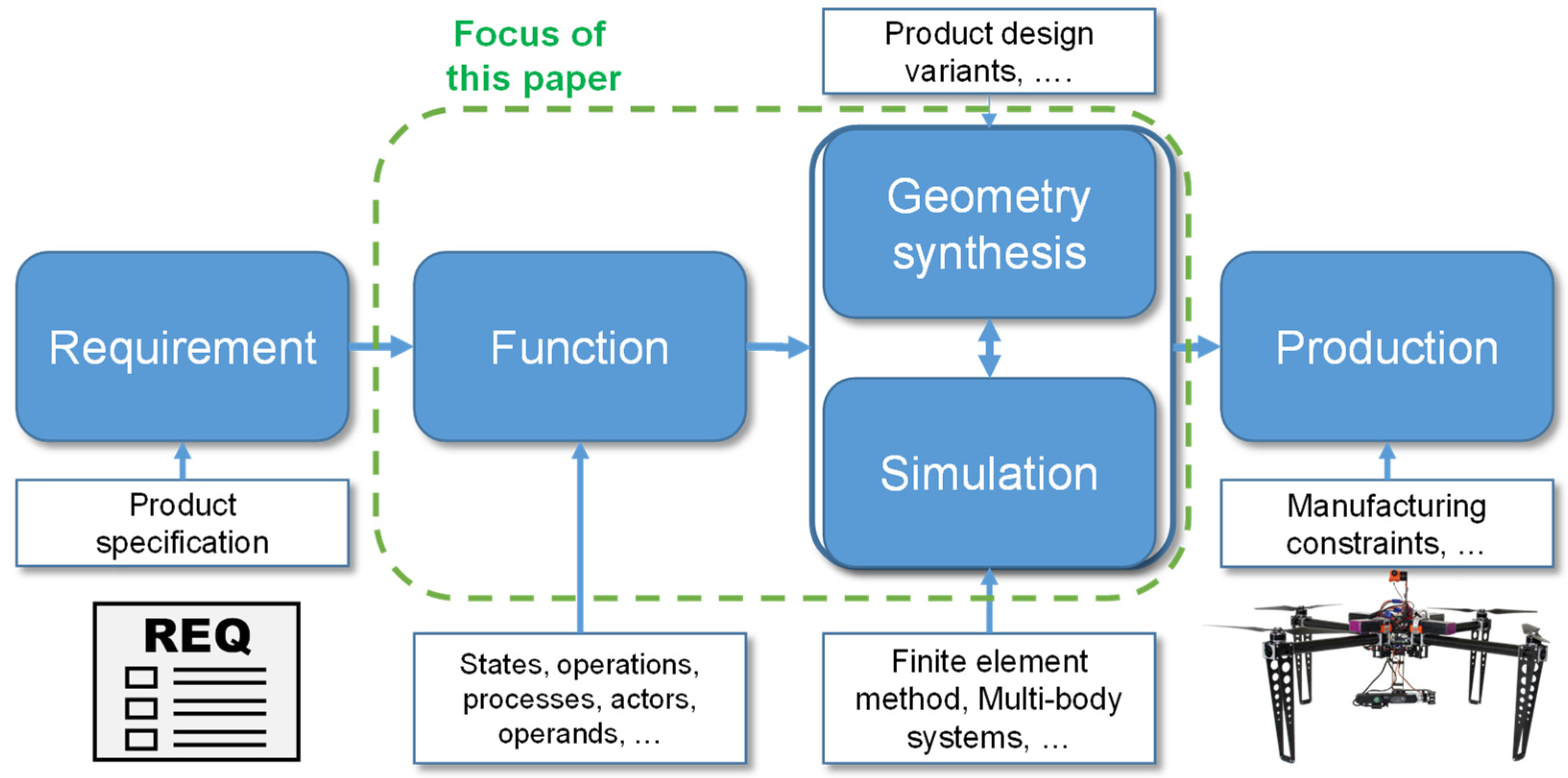
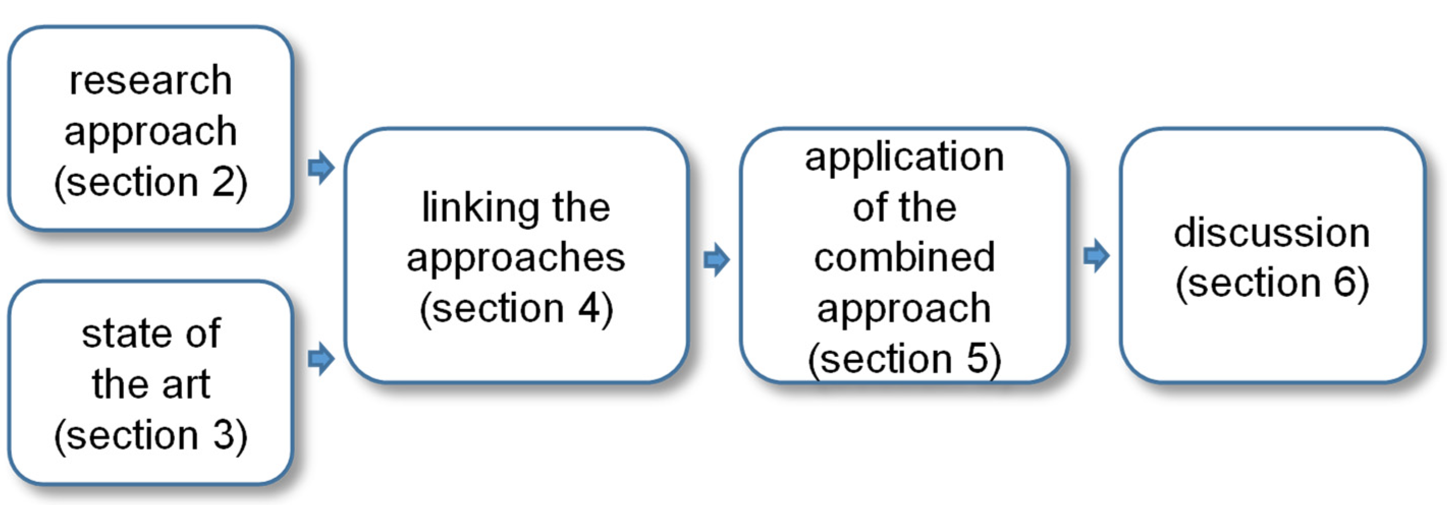
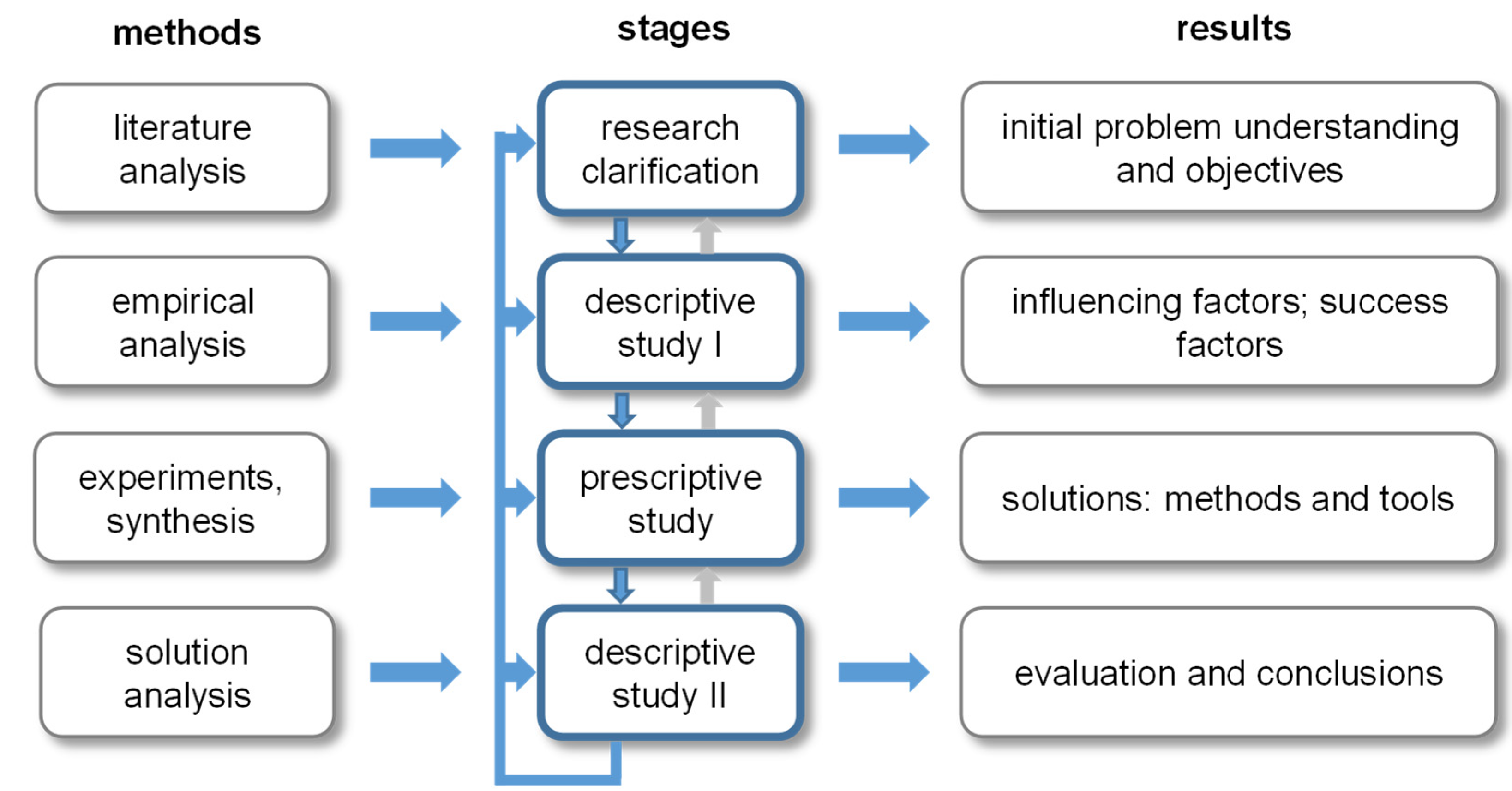
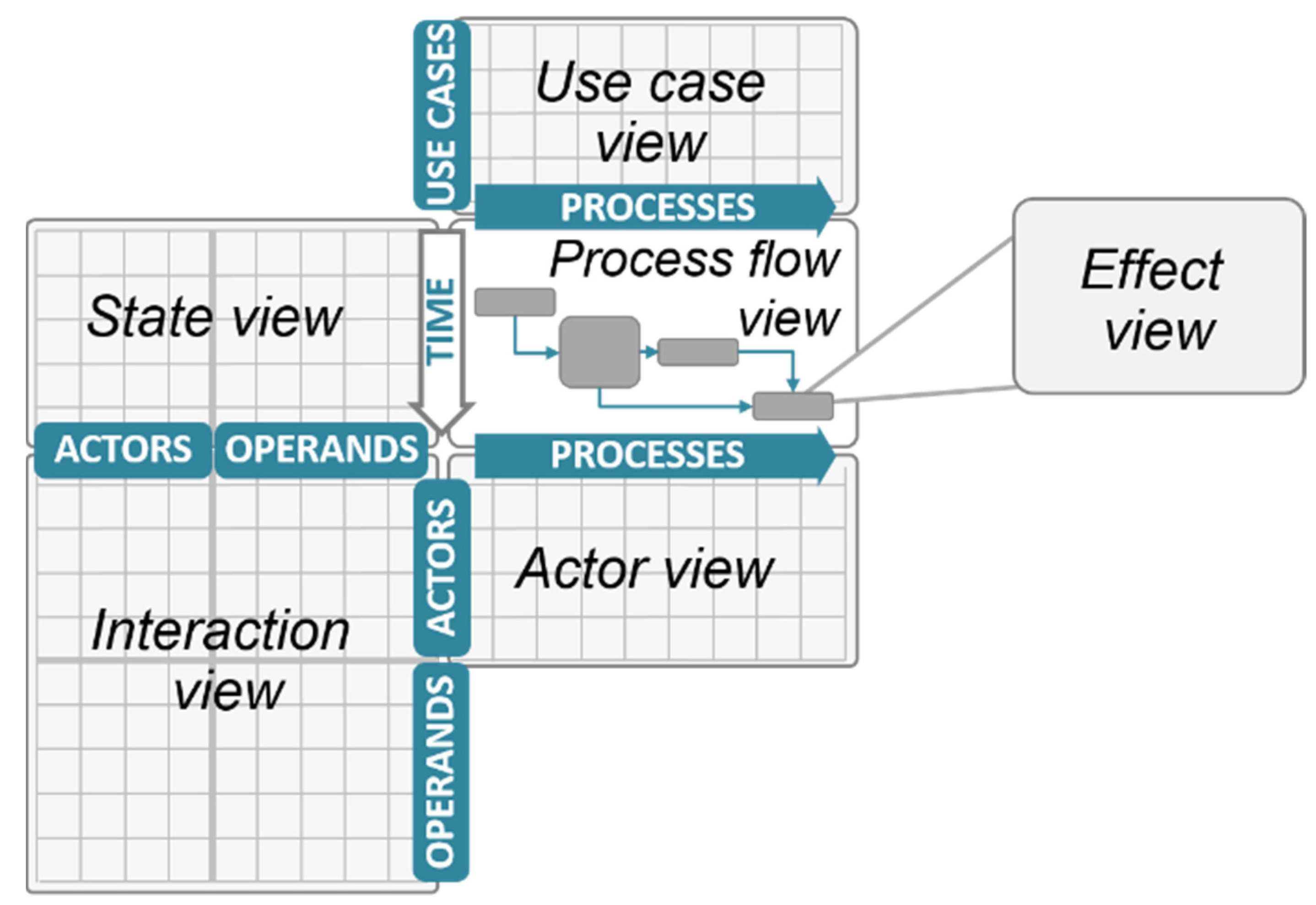
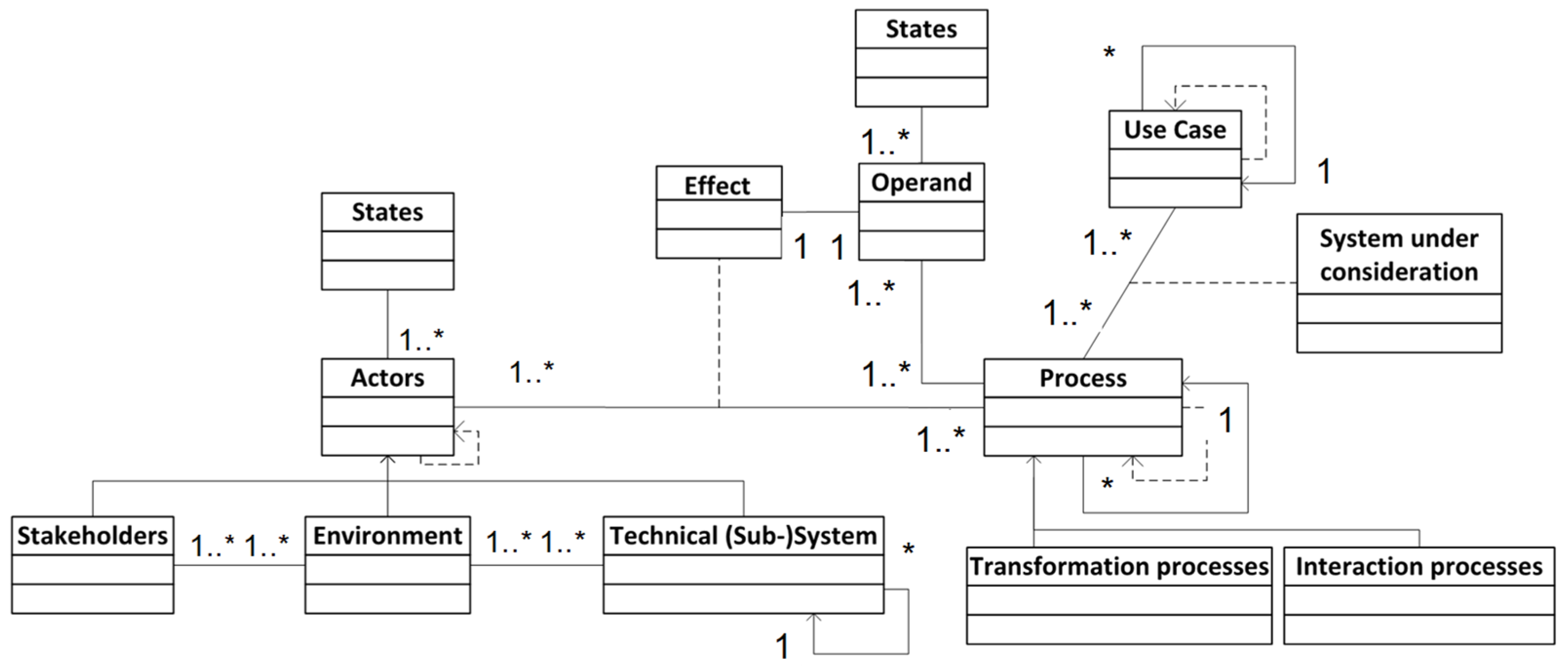
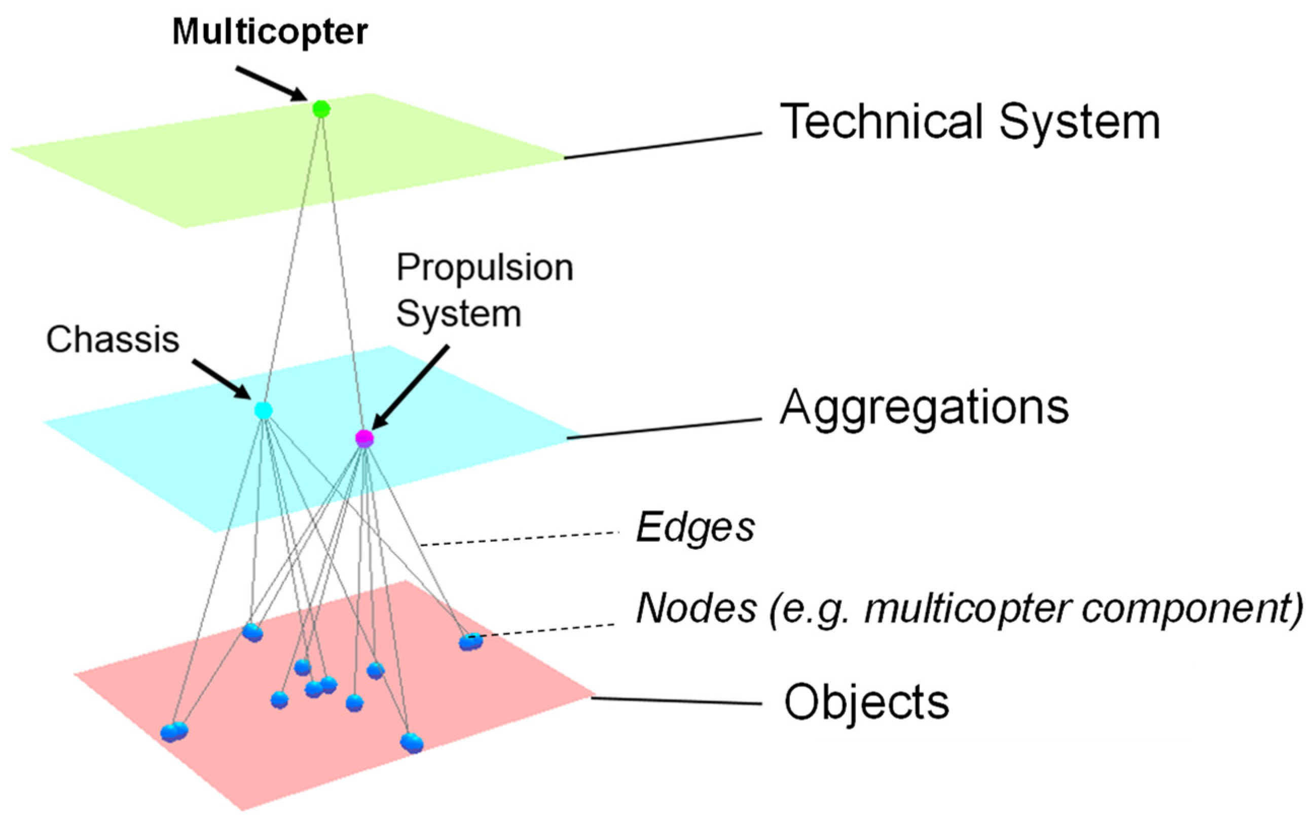
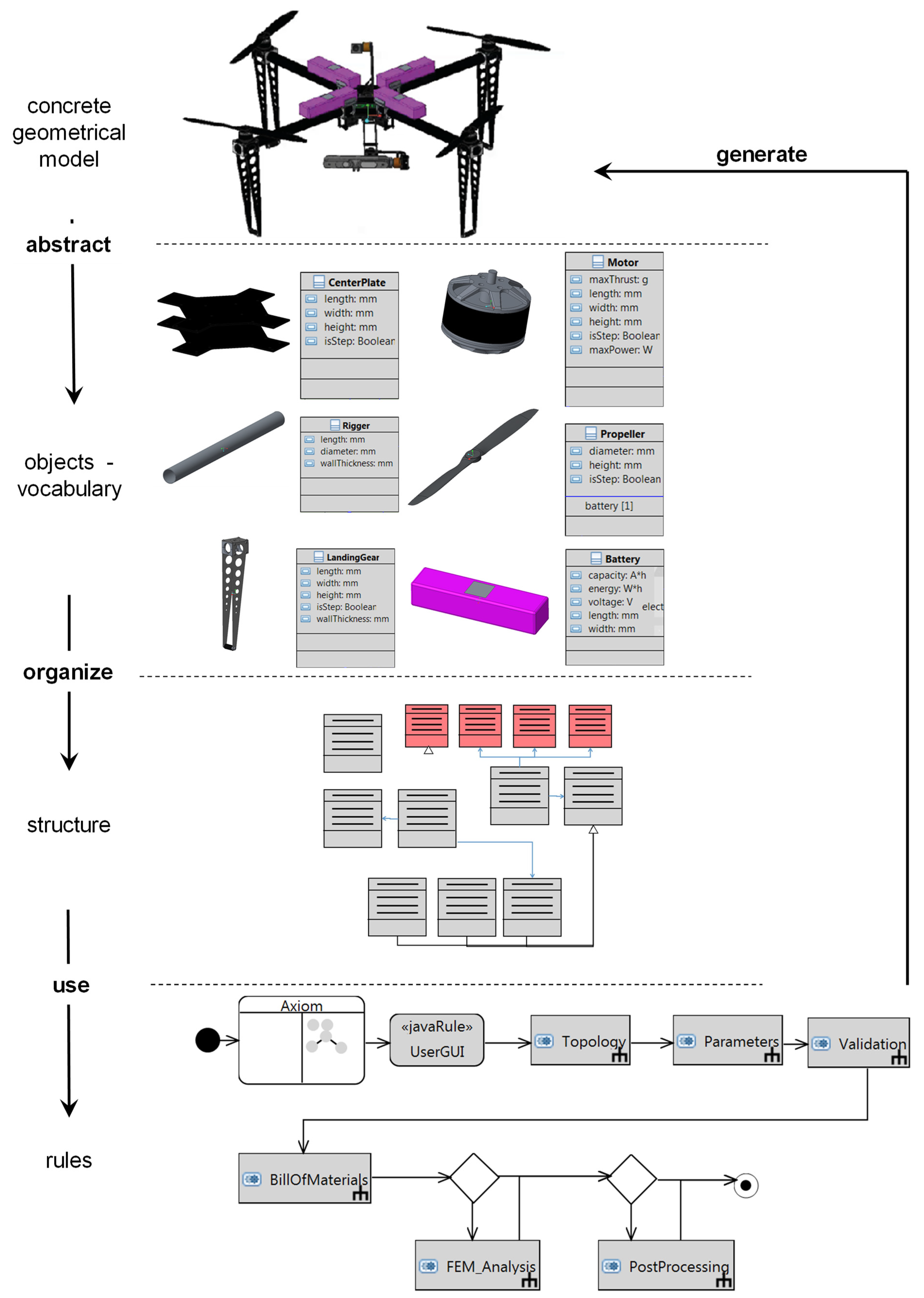
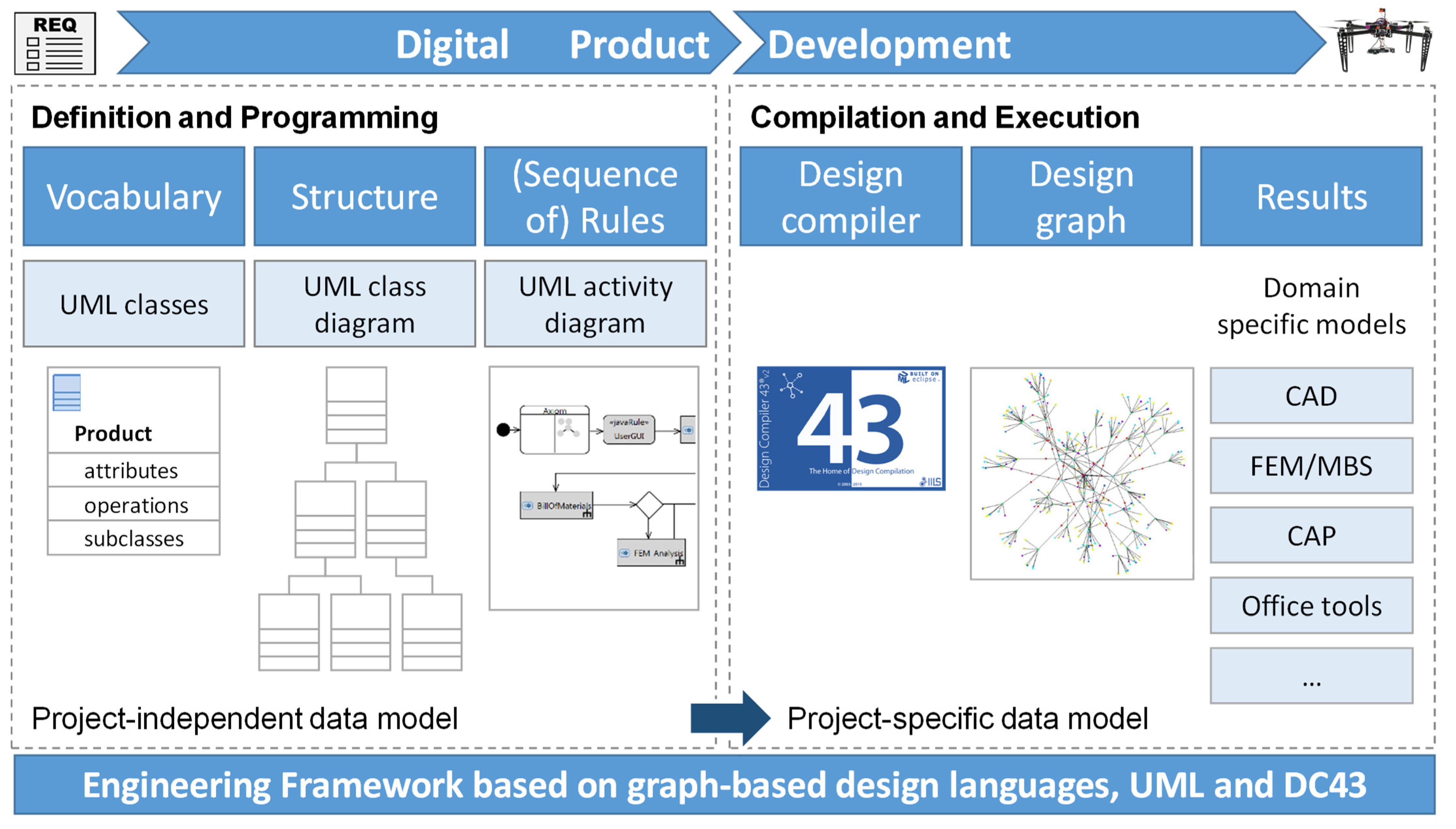
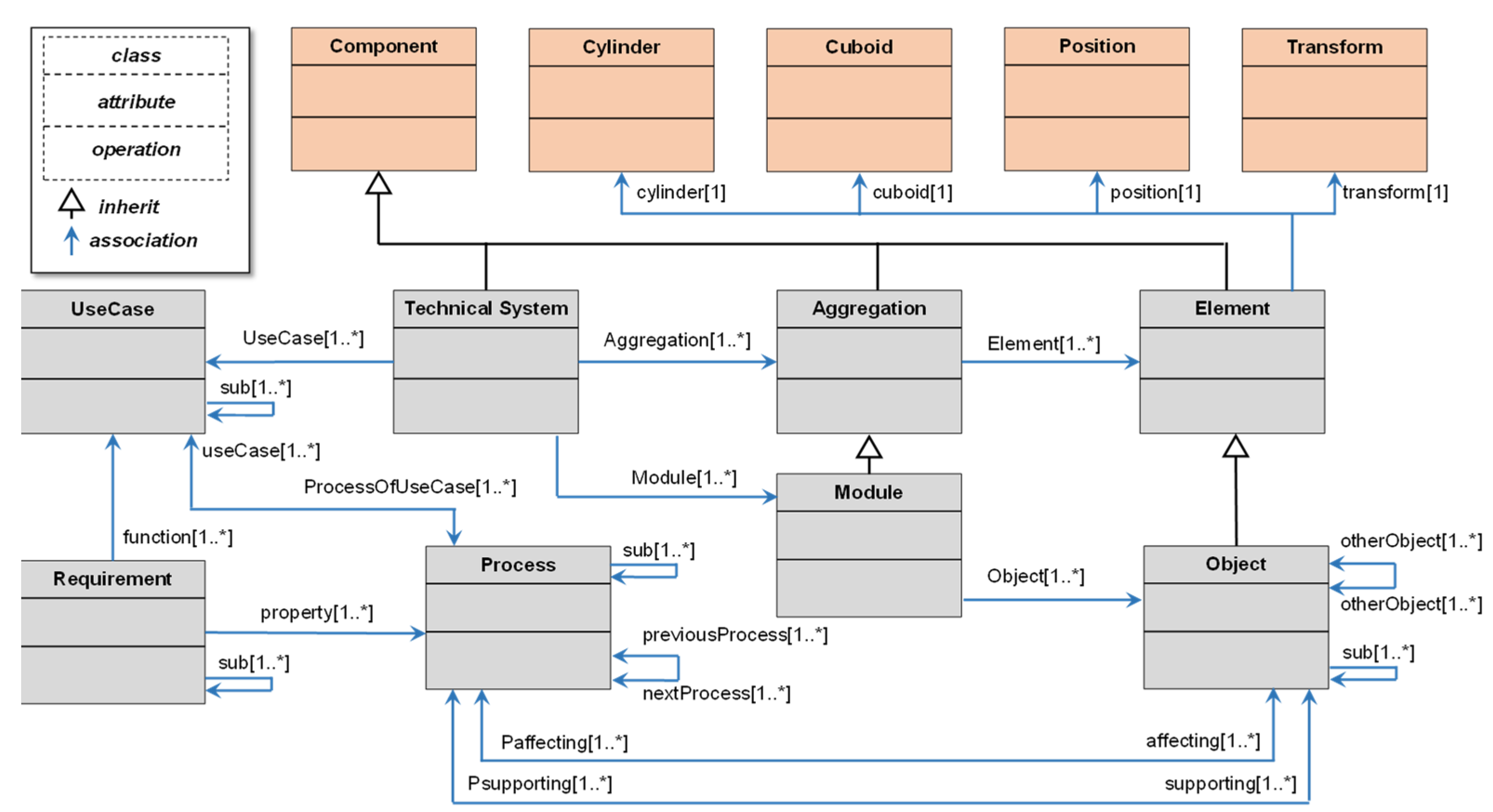
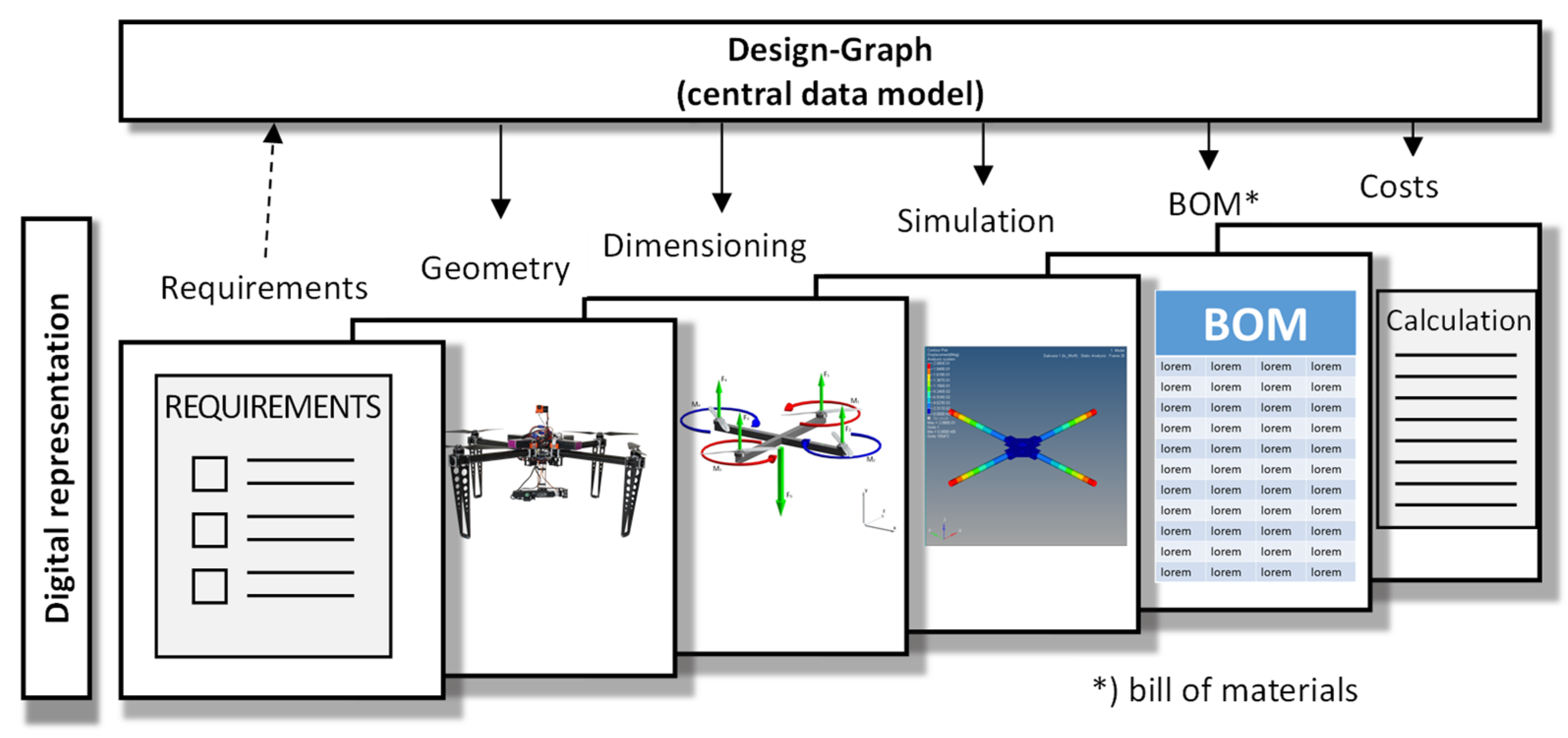
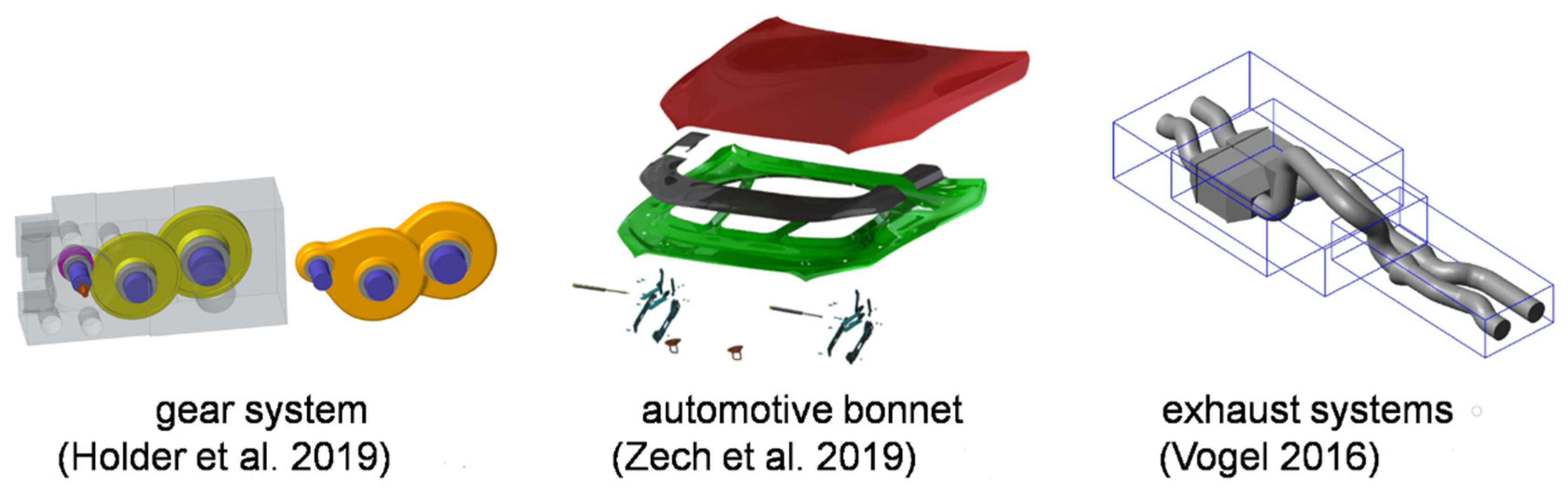
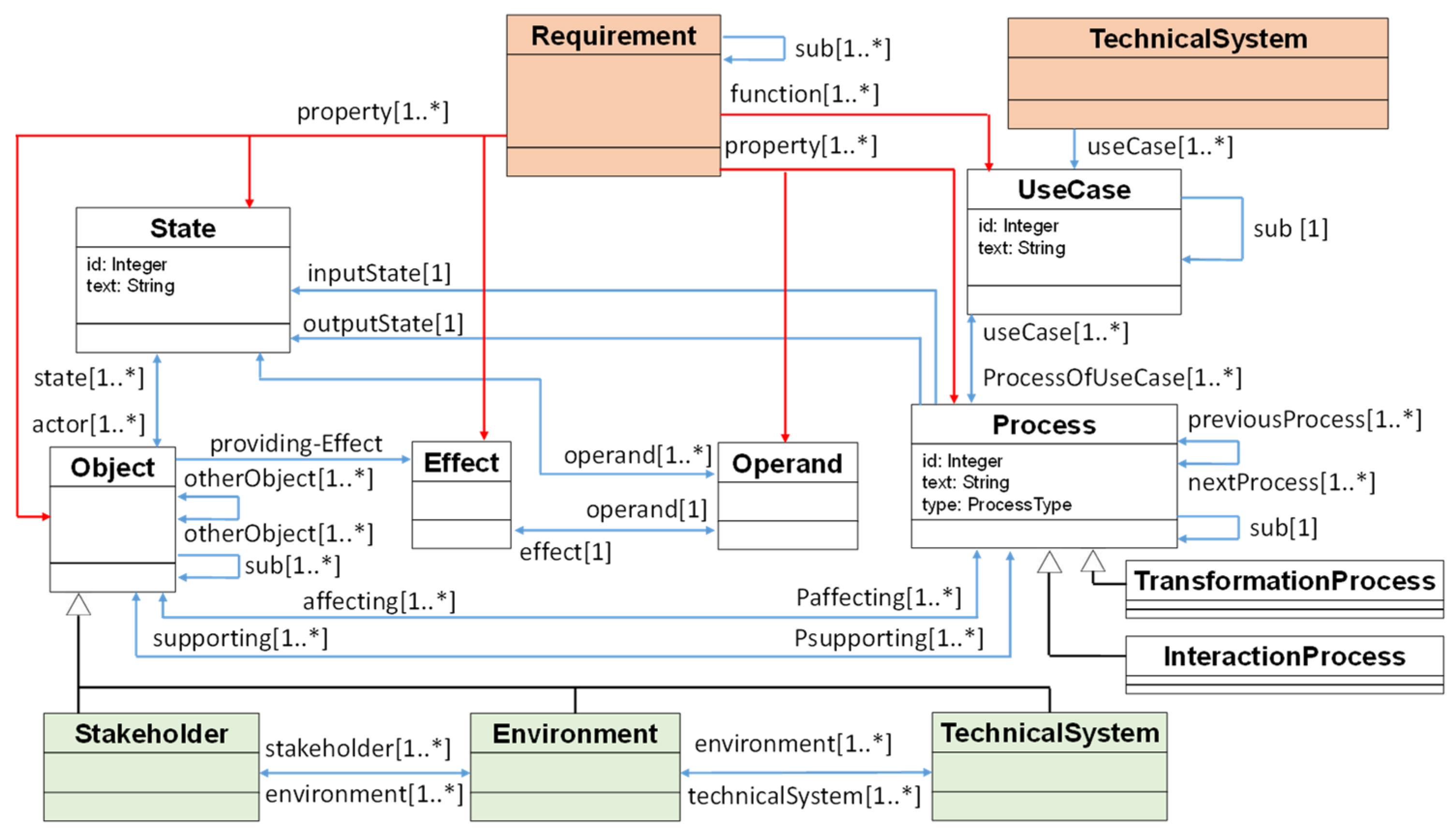
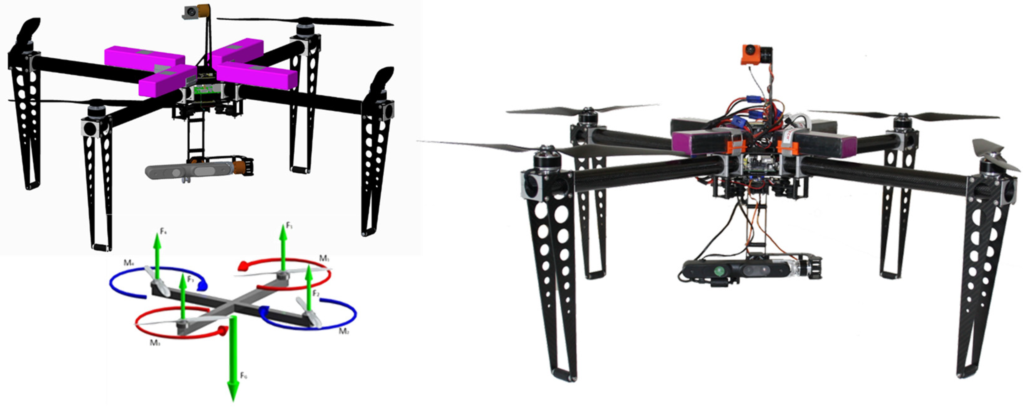
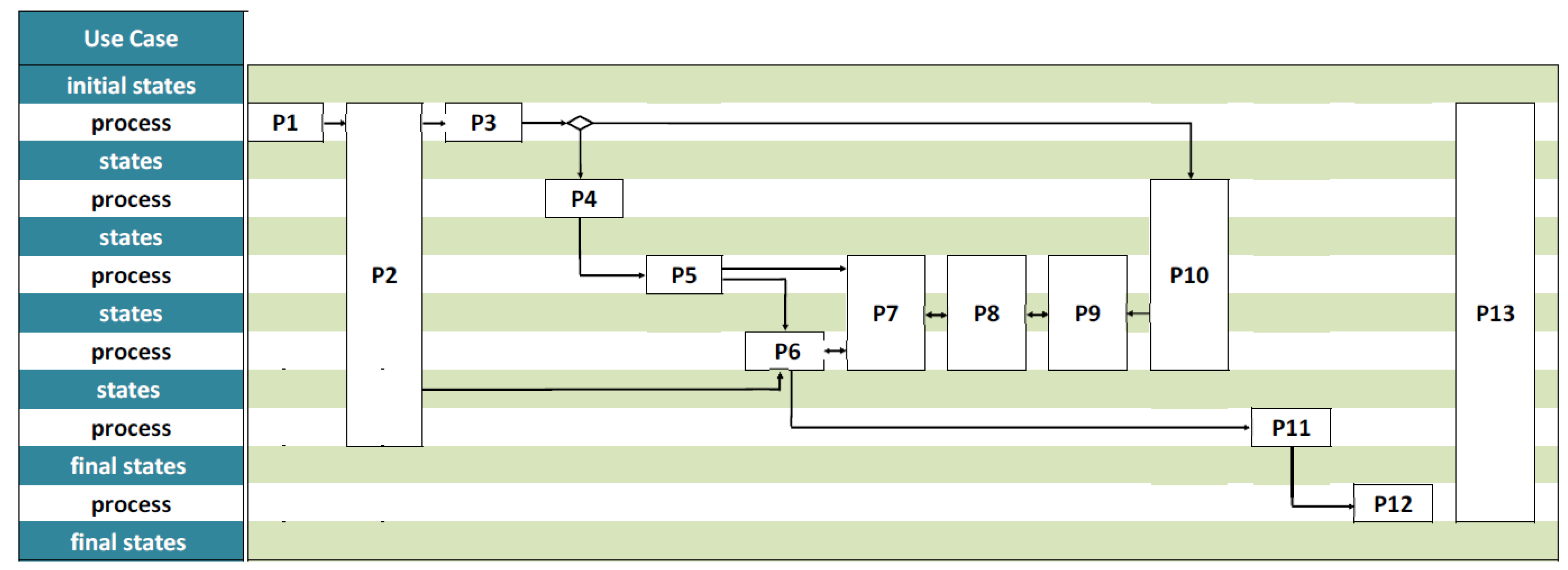
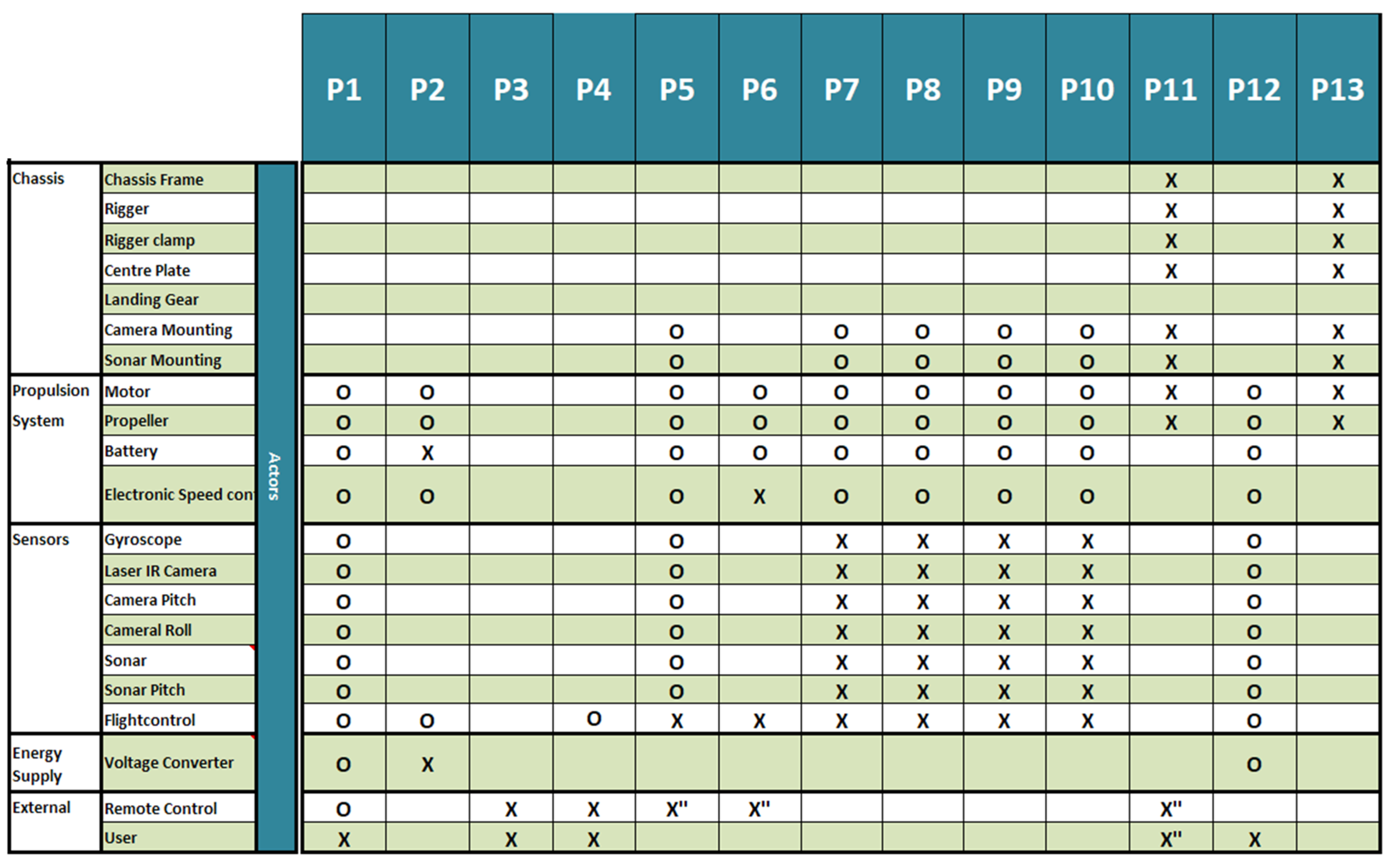
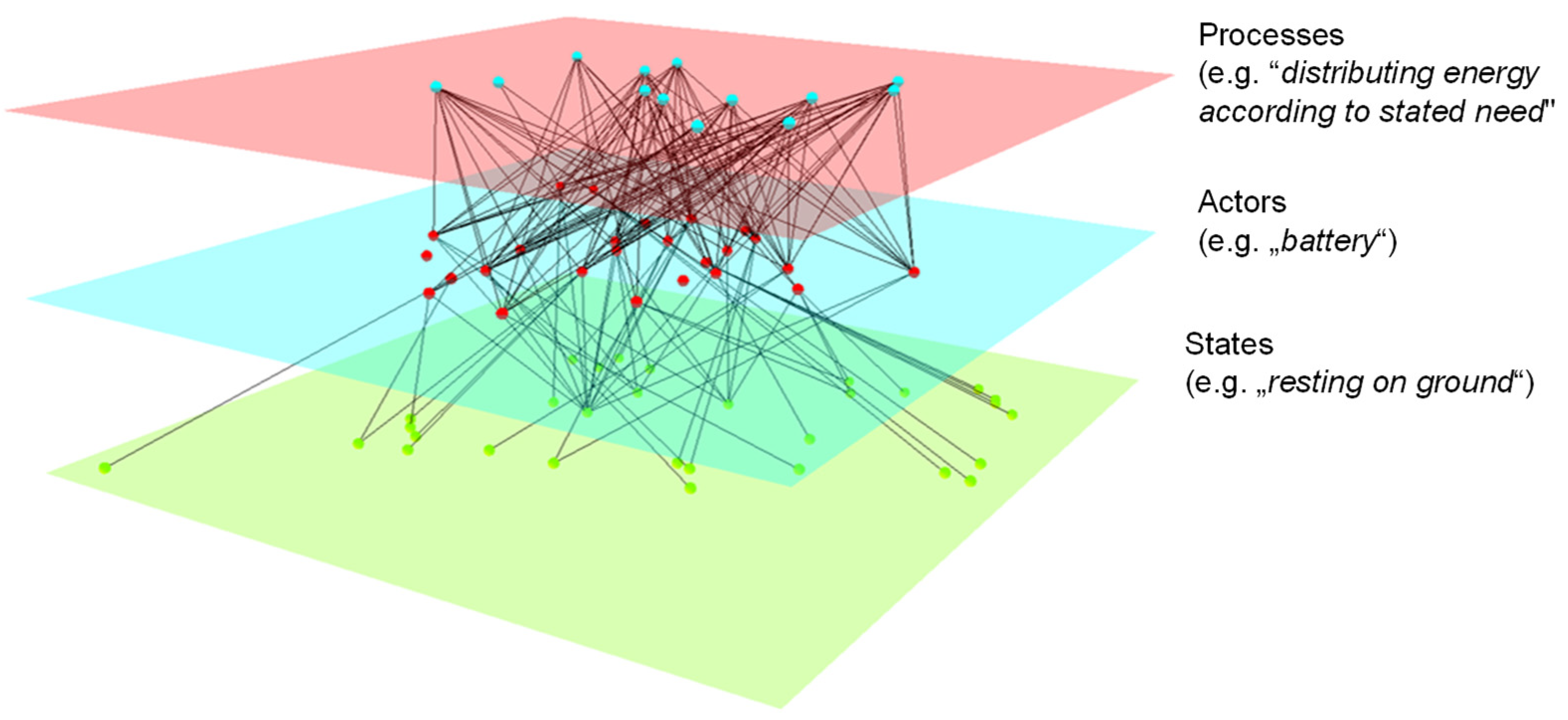
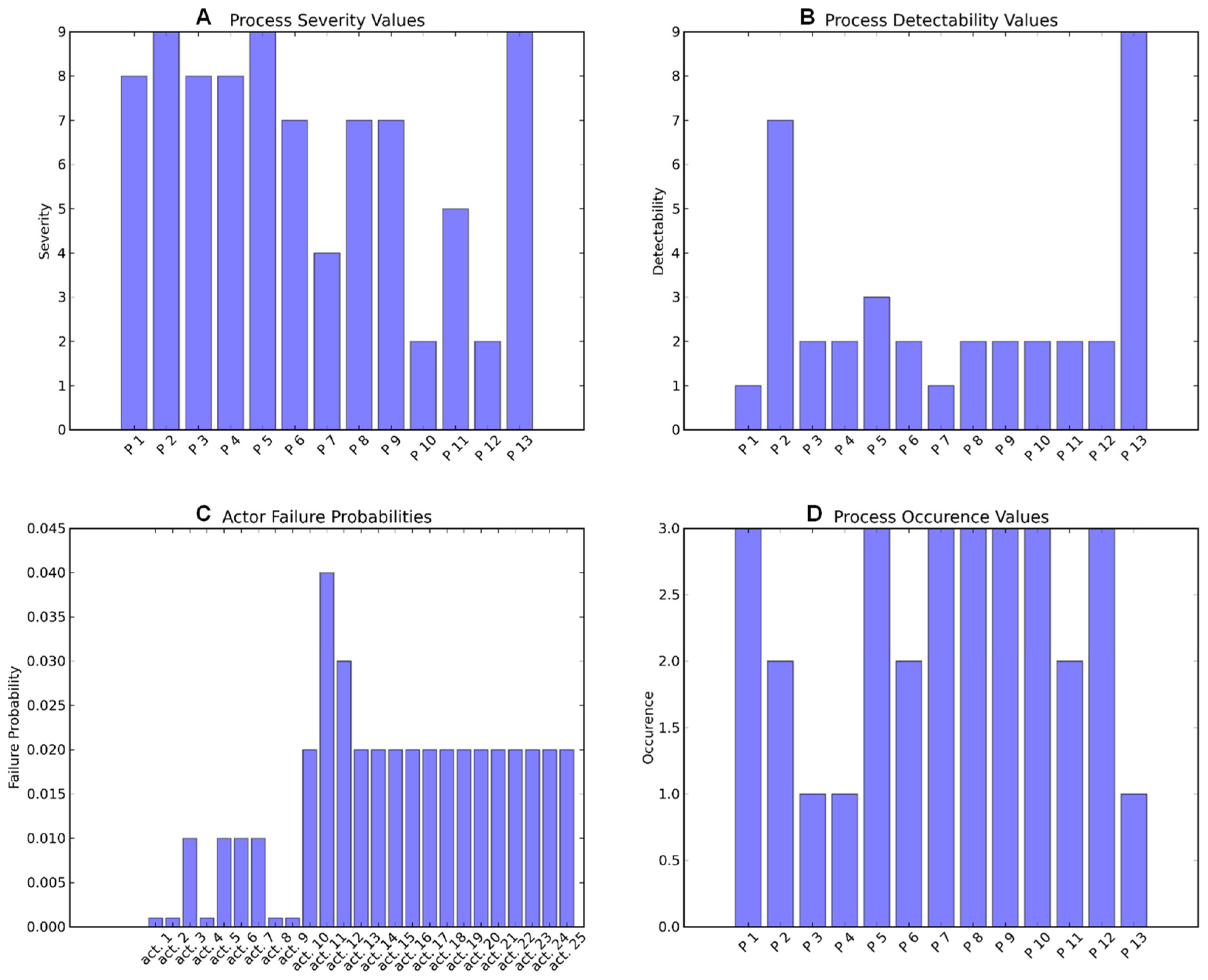
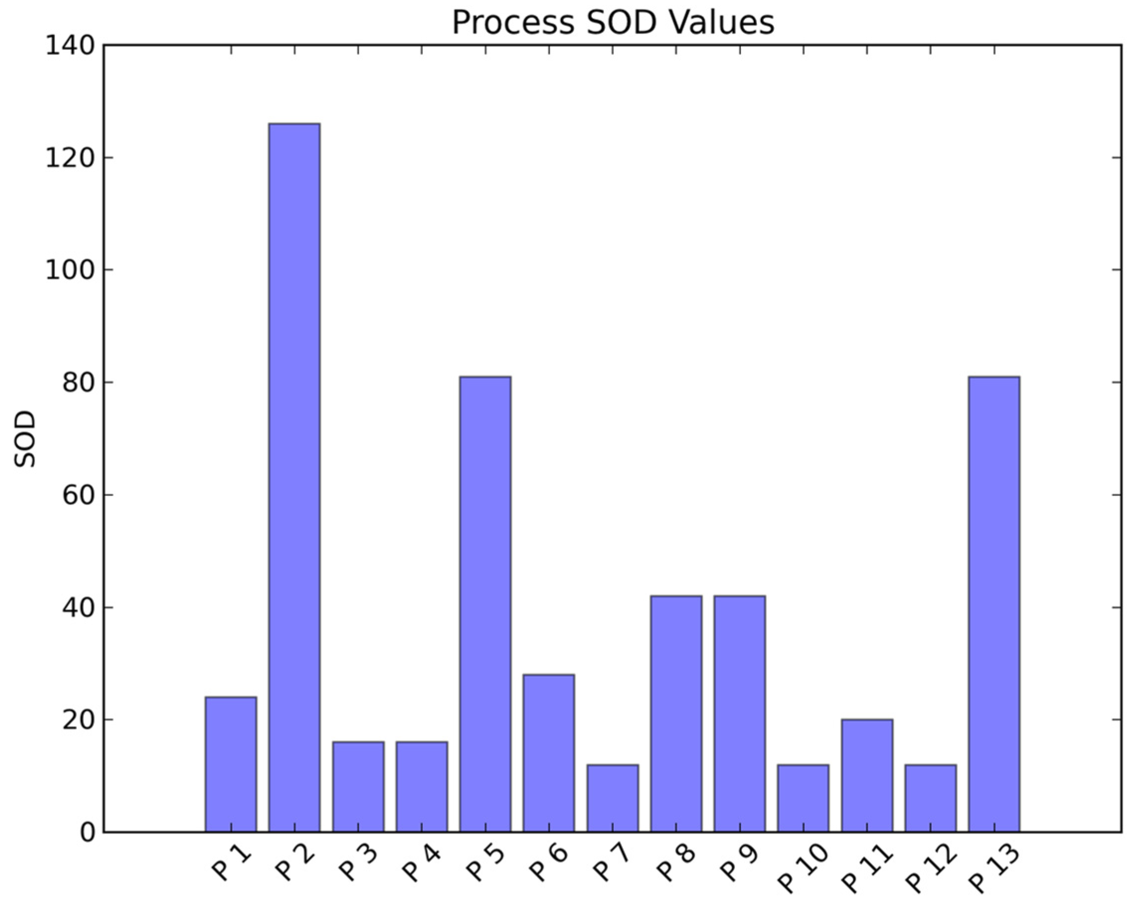
Table 1.
Associated views in the IFM Framework. Reprinted with permission from [17].
Table 1.
Associated views in the IFM Framework. Reprinted with permission from [17].
| View | Description |
|---|---|
| Process flow view | The main aim of the process flow view is to visualize the flow of sequential or parallel processes that are related to one specific use case in a qualitative manner. These processes may be interaction or transformation processes. For every use case, a set of views is generated, which is associated with the use case. In the horizontal direction, process blocks are arranged from left to right for enabling a direct link to the actor view below. Vertically, the process flow is visualized in relation to time; this corresponds to the gradual evolution of states in the associated state view. |
| State view | The main aim of the state view is to represent the states from the initial state to the final state of both operands and actors and also of the changes of states associated with the related processes. |
| Actor view | The main aim of the actor view is to indicate the involvement of one or more actors in the realization of processes. The involvement of these actors can be active or passive. The actors can be part of the system or can be in the surrounding of the system. |
| Use case view | The main aim of the use case view is to indicate the involvement or association of processes in the different use cases. |
| Effect view | The main aim of the effect view is to represent the effects that enable certain processes. The effects are provided by actors. For every process block included in the process flow view, a separate effect view can be generated. |
| Interaction view | The main aim of the interaction view is to map the bilateral impacts between actors and operands and also their complementary contributions or other kinds of dependency between them in the realization of use cases and associated processes. The interaction view represents the structure of the system. |
Table 2.
Entities in both approaches and their counterparts (state prior to linking activities).
| Entities in the IFM Framework | Entities in the Engineering Framework Based on UML, GBDL and DC43 |
|---|---|
| State (of operands) | Implicitly represented in attributes and operations |
| Operand | Implicitly represented in attributes and operations |
| Effect | Not yet represented |
| States (of actors) | Implicitly represented in attributes and operations |
| Actors (inheritance and hierarchy not expressed) | Object |
| Process | Process |
| Use case | UseCase |
| Not yet expressed | Requirement |
| System under consideration | TechnicalSystem |
| Transformation and interaction processes | Not yet represented |
| Stakeholders | Not yet represented |
| Environment | Implicitly represented in attributes and operations |
| Technical (Sub-)System | Module |
| Not yet represented | Aggregation |
| Not yet represented | Element |
| Not yet represented | Imported classes (e.g., from geometry diagram) |
Table 3.
IF model processes of the function model of the multicopter.
| Number | Process |
|---|---|
| 1 | Starting system |
| 2 | Distributing energy according to stated need |
| 3 | Sending steering command |
| 4 | Sending steering command via remote |
| 5 | Calculating flightpath and motor engagement |
| 6 | Increasing or decreasing rotation speed of drive motors |
| 7 | Tracking left |
| 8 | Tracking rate of ascent or descent |
| 9 | Tracking roll rate and roll angle |
| 10 | Holding position |
| 11 | Landing multicopter |
| 12 | Switching system off |
| 13 | Distributing forces |
Publisher’s Note: MDPI stays neutral with regard to jurisdictional claims in published maps and institutional affiliations. |
© 2022 by the authors. Licensee MDPI, Basel, Switzerland. This article is an open access article distributed under the terms and conditions of the Creative Commons Attribution (CC BY) license (https://creativecommons.org/licenses/by/4.0/).
Share and Cite
MDPI and ACS Style
Elwert, M.; Ramsaier, M.; Eisenbart, B.; Stetter, R.; Till, M.; Rudolph, S. Digital Function Modeling in Graph-Based Design Languages. Appl. Sci. 2022, 12, 5301. https://0-doi-org.brum.beds.ac.uk/10.3390/app12115301
AMA Style
Elwert M, Ramsaier M, Eisenbart B, Stetter R, Till M, Rudolph S. Digital Function Modeling in Graph-Based Design Languages. Applied Sciences. 2022; 12(11):5301. https://0-doi-org.brum.beds.ac.uk/10.3390/app12115301
Chicago/Turabian StyleElwert, Michael, Manuel Ramsaier, Boris Eisenbart, Ralf Stetter, Markus Till, and Stephan Rudolph. 2022. "Digital Function Modeling in Graph-Based Design Languages" Applied Sciences 12, no. 11: 5301. https://0-doi-org.brum.beds.ac.uk/10.3390/app12115301
Note that from the first issue of 2016, this journal uses article numbers instead of page numbers. See further details here.