Article

Failure Mechanism Analysis and Optimization Analysis of Tunnel Joint Waterstop Considering Bonding and Extrusion

1
School of Civil Engineering, Central South University, Changsha 410075, China
2
China Railway 21st Bureau Group the 3rd Engineering Co., Ltd., Xianyang 712023, China
3
Hubei Provincial Communications Planning and Design Institute Co., Ltd., Wuhan 430050, China
4
Hubei Provincial Communications Investment West Hubei Expressway Construction Management Co., Ltd., Wuhan 430000, China
*
Author to whom correspondence should be addressed.
Submission received: 13 May 2022 / Revised: 3 June 2022 / Accepted: 4 June 2022 / Published: 5 June 2022
(This article belongs to the Special Issue Advanced Underground Space Technology)

Abstract

:
In waterproofing mountain tunnels, the tunnel joint is the weak link. To explore the waterproof failure mechanism of the tunnel joint waterstop belt and to propose an optimization method for the waterstop belt, this paper combines tests and numerical simulations, summarizes the waterproofing mechanism of the waterstop belt, establishes a finite element model of the waterstop belt considering bonding and extrusion, and studies the waterproofing ability and mechanical properties of the waterstop. The main conclusions are as follows: (1) The waterproofing capacity of the water stop belt depends on its surface contact pressure and bonding force. (2) Waterstop deformation will partially destroy the bonding between the waterstop and concrete, reducing the reliability of the waterproofing mechanism. (3) When the deformation of the waterstop belt reaches a certain degree, its stress value is too large to meet the requirements of its service life. (4) The design can be optimized from two aspects: the bond between the waterstop and concrete, and the size of the waterstop.

1. Introduction

With the continuous increase in traffic in China, the scale of tunnels continues to increase and a large number of technical problems have been encountered during the construction and operation of tunnels. Most tunnels have varying degrees of issues, among which tunnel leakage is one of the most common, affecting the normal service use of tunnels [1,2]. Although railway and highway mountain tunnels use a special anti-drainage system [3], quite a few tunnels face serious leakage soon after they are built, and in China, there is even a saying: “ten tunnels and nine leaks”. An anti-drainage system may be damaged during construction and service, in which case, when the groundwater pressure is great, the water will penetrate the waterproof layer [4]. In this case, the waterproofing of the concrete lining becomes the key to the waterproofing of the entire tunnel project. Lining joints are undoubtedly the weak link in the waterproofing of lining structures [5]. To avoid water leakage through these joints, waterstops are generally used.
However, in actual projects, it is often difficult to achieve the desired effect through waterstop waterproofing. To meet the requirements of tunnel waterproofing, scholars at home and abroad have made a lot of optimizations. Some scholars [6,7,8] believe that the existing waterstop structure is not reasonable enough, based on which the structure of the waterstop has been optimized. Some studies [9,10,11,12,13] indicate that improving the adhesion of waterstops to concrete can effectively improve its waterproofing performance. On the basis of the contact between the waterstop and concrete, some scholars [14,15,16] have proposed inflatable waterstops, bituminous surface waterstops, and flexible waterstops as options. According to Kudritz [17], a proper waterstop profile is critical. The above analysis of the causes of failure of a waterstop is based on engineering experience, and there is no theoretical analysis of this, which makes it difficult to explain the rationality of its optimization measures.
Some scholars [18,19,20,21] have simulated the waterstop zone through finite element analysis, analyzing its stress and deformation characteristics. Lin [22] simulated the deformation of the waterstop of the deformed seam of the pipe gallery, analyzed the stress characteristics of the waterstop under different working conditions, and optimized the structure of the existing waterstop. Meng and Li [23,24] simulated the drawing of rubber strips and the deformation of the optimized waterstop, and analyzed the stress characteristics of the waterstop. They adopted the method of binding or applying tangential friction to the contact between the waterstop and the concrete, but did not consider the adhesion of the waterstop and the concrete, which is more limited. At the same time, the extrusion effect of concrete on the waterstop was considered, nor was the failure mechanism of the waterstop waterproofing studied. Only the deformation stress characteristics of the waterstop were analyzed.
In this paper, the buried rubber waterstop commonly used in the project is the research object, and the waterproofing principle of the waterstop, the bonding of the waterstop and concrete, the extrusion effect of the concrete pouring, etc., are taken into account to carry out the finite element analysis, study the failure characteristics, and propose the relevant optimization scheme to provide a reference for the optimization of the waterproof measures of the mountain tunnel joint.

2. Analysis of the Working Mechanism of the Buried Waterstop

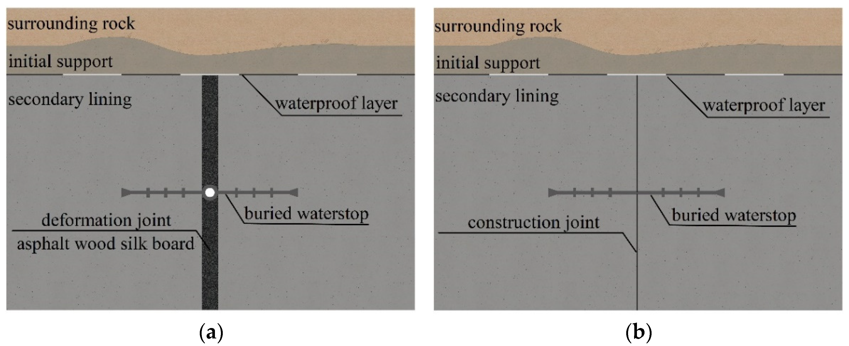
2.1. The Working State of the Buried Waterstop

The ring joints of mountain tunnels are generally divided into two categories: deformation joints and construction joints, and the buried waterstop belt is set along the ring in the middle of the lining thickness, as shown in Figure 1. The following two kinds of deformation often occur in the tunnel: (1) longitudinal uneven settlement due to uneven distribution of the stratum and surrounding load changes and (2) longitudinal telescopic settlement due to the temperature difference, concrete shrinkage and creep, and vehicle load.
The deformation joint is set mainly to improve the uneven force deformation of the tunnel, which is generally divided into settlement joints and telescopic joints, and the width should be 20 to 30 mm. The specification stipulates that the maximum allowable settlement difference of the deformation joint for settlement shall not be greater than 30 mm [25]. There is no clear provision on the maximum allowable telescopic value of the deformation joint, which can be calculated by referring to the available literature [26,27] and taking into consideration unfavorable conditions and a certain safety factor. The maximum elongation amount of the deformation joint after rounding is 20 mm, and the maximum shortening amount is 10 mm.
In summary, when working normally, the buried waterstop at the deformation joint will be in an uneven settlement or telescopic state with the lining deformation. The maximum settlement value is 30 mm, the maximum elongation value is 20 mm, and the maximum compression value is 10 mm.

2.2. Waterproof Mechanism of a Buried Waterstop
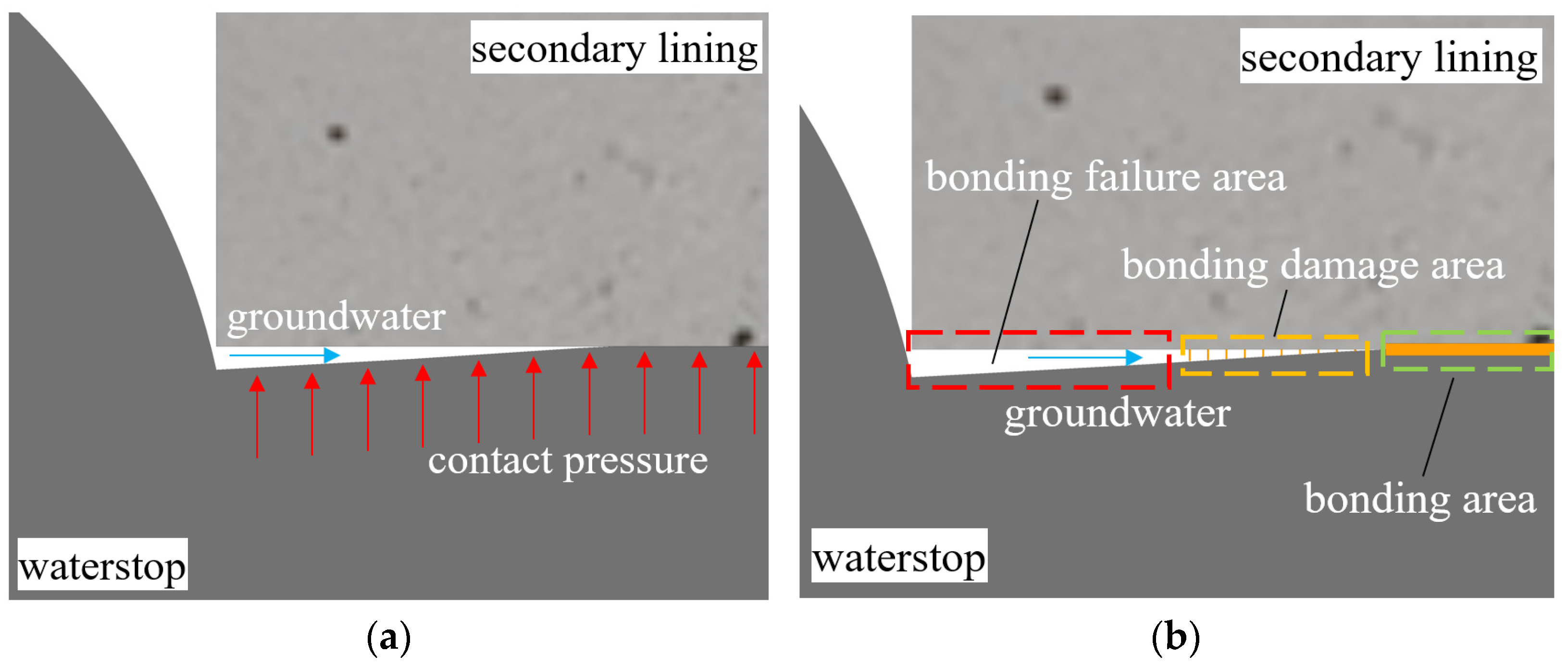
The waterproofing principle of a buried waterstop mainly includes the following two aspects:
(1)
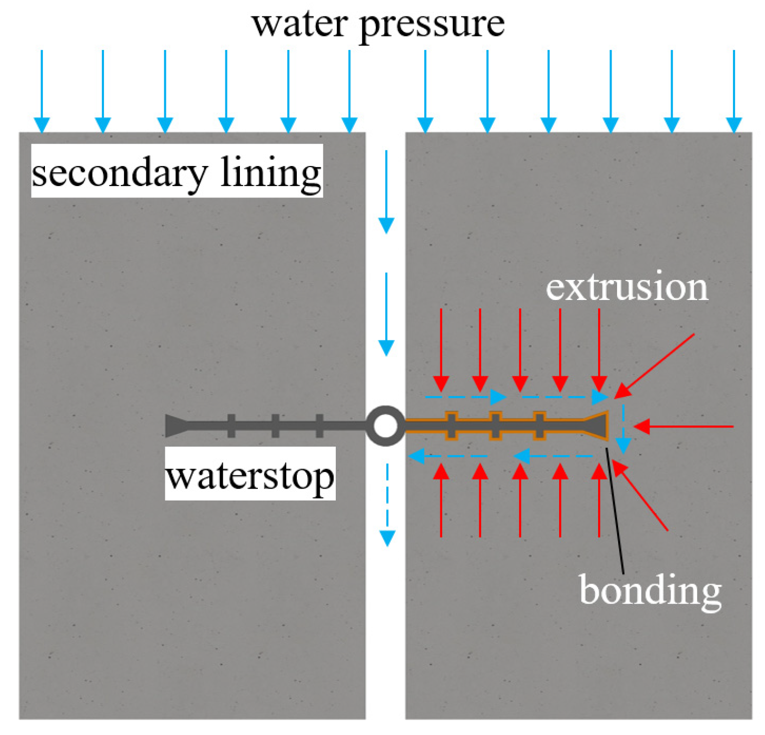
Extrusion sealing: in a similar way to the sealing principle of the shield tunnel rubber gasket [28,29], the rubber sealing belt transfers pressure to its contact surface. When extrusion occurs between the waterstop and the concrete lining, contact pressure is generated. Without considering the bonding force between the waterstop belt and concrete, leakage occurs when the water pressure is greater than the contact pressure (Figure 2a).
(2)
Bonding water plugging: There is a bond between the contact surface of the buried waterstop and the concrete lining. Without considering the sealing of the waterstop belt, when the water pressure is greater than the bond force, the bond area experiences “intact–damage–failure” and then leakage occurs (Figure 2b).
Figure 2. Waterproofing mechanism of a waterstop. (a) Extrusion sealing, (b) Bonding water plugging.
Applsci 12 05737 g002
If the extrusion seal and bonding of the waterstop are simultaneously considered, when the water pressure is greater than the contact pressure, the contact pressure will fail. The bonded area then begins to be stressed, and the magnitude of the force is the water pressure minus the contact pressure. As the water pressure increases, the bonded area enters the damage stage, and then completely fails, at which point the waterstop belt fails to block the water, and the tunnel joints leak.
The force of the waterstop preventing groundwater from passing through the seepage channel is called water infiltration resistance (Figure 3). The waterproofing ability of the waterstop depends on its water infiltration resistance, involving contact pressure and adhesion force. When water infiltration resistance is greater than water pressure, the waterstop can play a waterproofing role, that is:
Pwl ≥ γPw
Pwl = F + C
where Pwl is the water infiltration resistance, Pw is the theoretical water pressure, γ is the safety factor, F is the contact pressure, and C is the adhesion force. At the same time, the long seepage path formed by the complex cross-sectional form of the waterstop can improve the waterproof reliability of the joint, remove the head pressure, and increase the difficulty for groundwater to seep through the tunnel joint.
As can be seen from the preceding discussion, tunnel joint deformation constantly changes with temperature, load, etc., and with the development of deformation, the contact pressure between the waterstop and the concrete may change (Figure 4). The bonding of the waterstop to the concrete may also break with deformation, and the resistance of the waterstop to water seepage will also change. The water infiltration resistance after waterstop deformation can be regarded as short-term, P wl st , and the water infiltration resistance when the waterstop is not deformed can be regarded as long-term, P wl lt .
At the same time, according to relevant research reports, the service life of artificial rubber and other polymers can reach more than 100 years when the stress level does not exceed 20% of their tensile strength at fracture [30]. According to the specification, the tensile strength of the rubber waterstop is not less than 10 MPa, so the dangerous stress value is 2 MPa. In the following section, using test and finite element analysis, the failure characteristics of a waterstop will be studied from two aspects: water infiltration resistance and forced deformation of the waterstop.

3. Analysis of Failure Characteristics of a Buried Waterstop

3.1. Bonding Strength Test and Initial Contact Pressure Calculation

The waterproofing ability of tunnel joints depends on their resistance to seepage, which is composed of bonding force and contact pressure. To obtain resistance of the waterstop to seepage and provide parameters for finite element analysis, the adhesive force of rubber and concrete is tested and the initial contact pressure of the waterstop belt is calculated when the joint is not deformed.

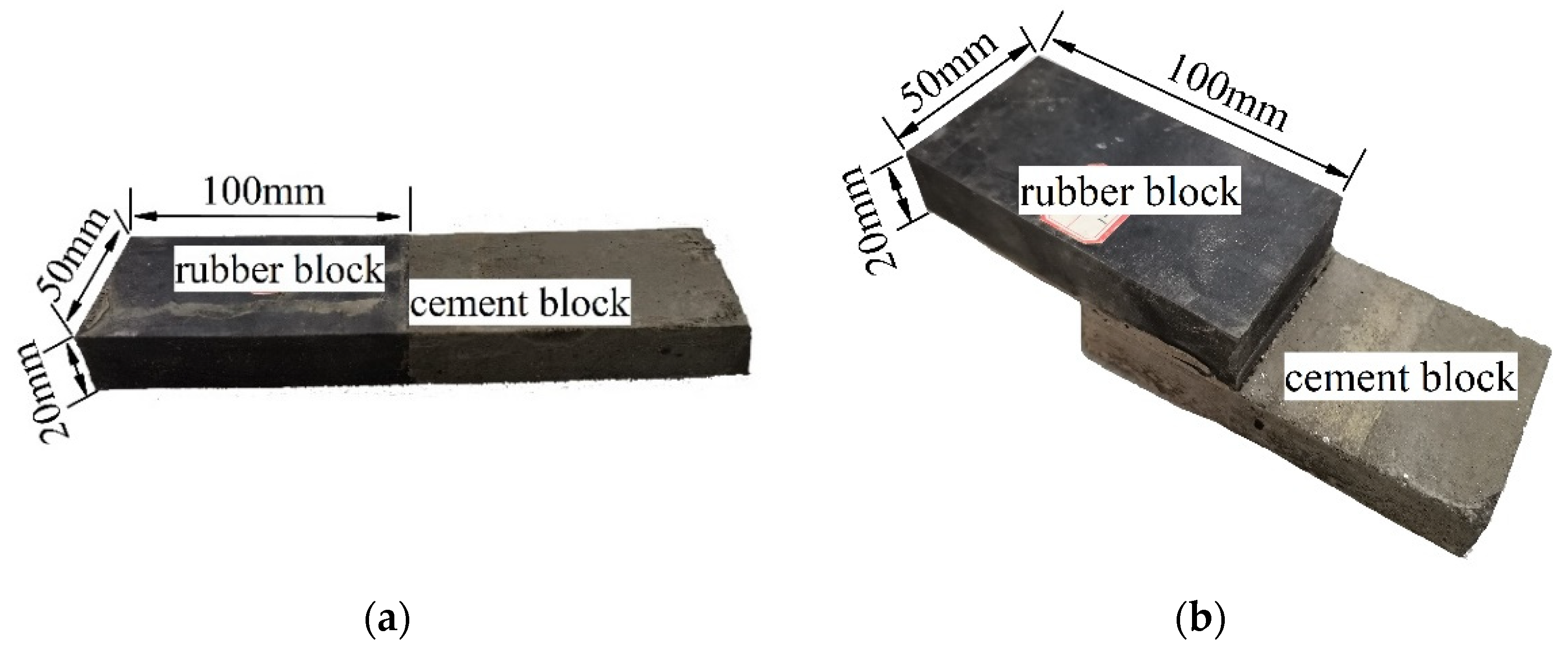
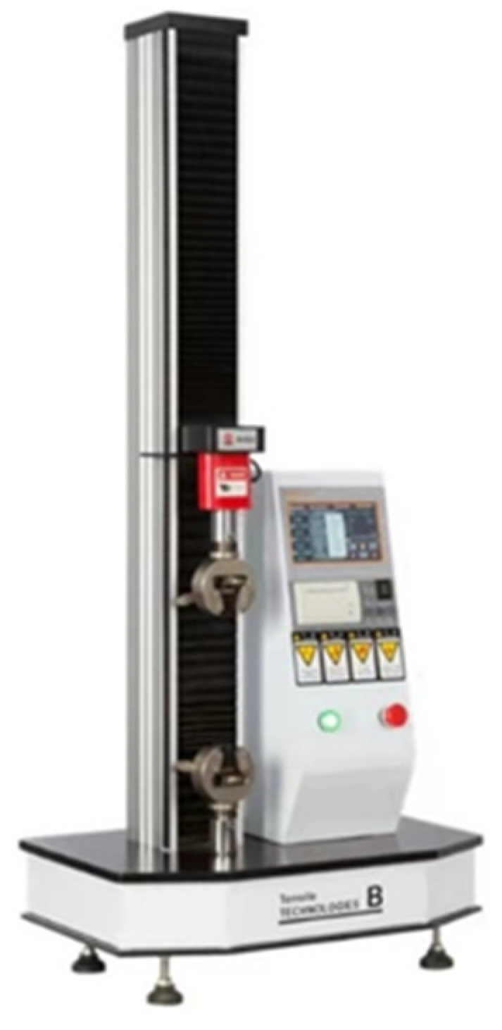
3.1.1. Adhesive Strength Test of Rubber and Concrete

Since the test specimens in this test were small, and the bond between concrete and rubber is mainly the bond between cement mortar and rubber, cement test blocks were used instead of concrete in this test. The cement used was ordinary Portland cement, with a compressive strength of 42.5 MPa (28 d). The tensile bond strength and the shear bond strength of rubber–cement were used as evaluation indexes.
The rubber was cut into rectangular blocks of 100 mm × 50 mm × 20 mm. The size of the cement test block was the same as that of the rubber block. The better of the two ends of the rubber block was selected for pouring. After pouring, the specimen was left for curing for 28 days at a temperature of 20 ± 2 °C and a relative humidity of more than 95%. The specimens were divided into tensile and shear groups, with three in each group. The tensile bond strength test surface was a rectangle surface of 50 mm × 20 mm, and the shear bond strength test surface was a square surface of 50 mm × 50 mm (Figure 5).
A tension machine (0–1000 N) was used as test equipment (Figure 6). Since the specimen was rectangular, the bonding force between rubber and concrete was small, and the bonding interface brittle. So, the selected tensile speed was 0.1 mm/min.
The tensile or shear strength is the maximum stress that the test piece bears in the process of bond failure caused by an external force. The average strength of the three specimens in each group was taken as the test result (Table 1).

3.1.2. Initial Contact Pressure

When the tunnel joint is not deformed, the contact pressure between the waterstop belt and concrete is regarded as the initial contact pressure, and the initial contact pressure is formed by the extrusion of concrete pouring on the waterstop belt. The effect of concrete shrinkage on extrusion was ignored, extrusion simplification was regarded as the result of concrete self-weight, and the self-weight height was the vertical distance from the pouring surface to the initial setting of concrete. The tunnel lining of the project was analyzed. The casting time of the lining of a mold is 7 h, and the initial setting time of concrete is 2 h, so the extrusion pressure at each point of the tunnel can be known. The initial contact pressure at the vault was the smallest, with a size of 0.005 MPa (Figure 7). It increased continuously along the lining contour and then remained unchanged, with a maximum value of 0.048 MPa (Figure 7).

3.2. Finite Element Analysis of Force and Deformation of Waterstop

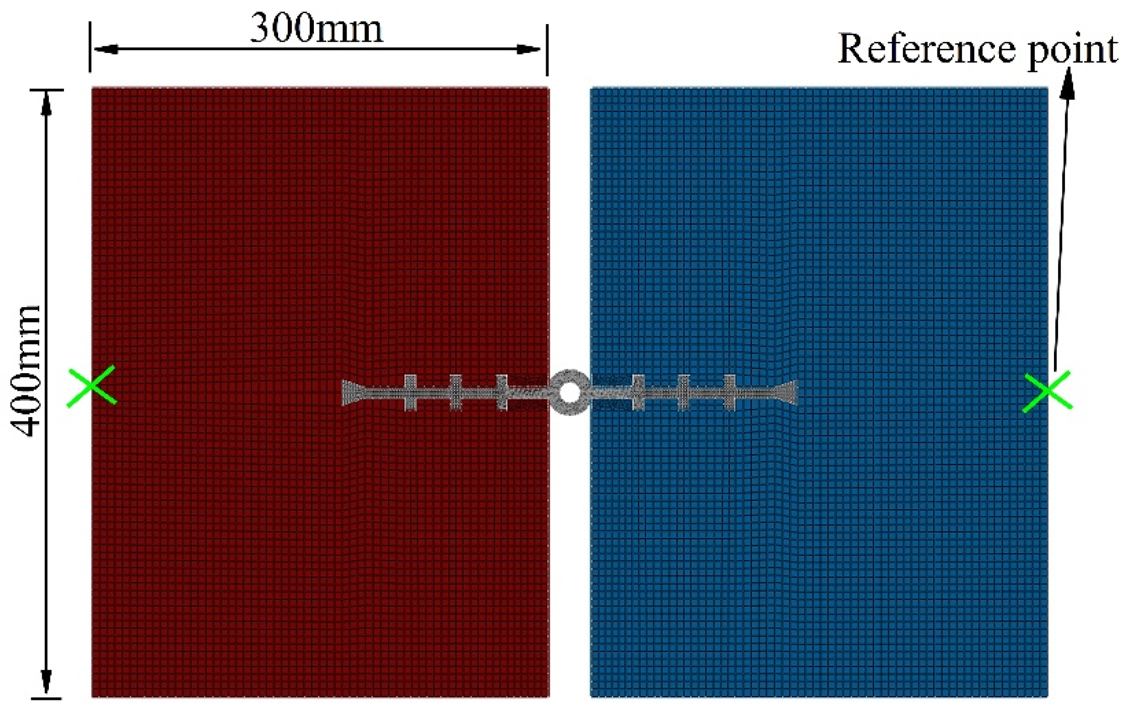
3.2.1. Finite Element Model

To analyze the impact of waterstop deformation on its waterproofing ability, ABAQUS/Standard is used to establish the plane strain finite element model of the buried waterstop in the concrete lining. The buried rubber waterstop is simulated by the Mooney–Rivlin model. The size is shown in Figure 8, and to distinguish it from the following, it is named waterstop I. The concrete damage-plastic model is used to simulate the tunnel lining, with a width of 300 mm and a height of 400 mm. The bonding of the waterstop and concrete is simulated by cohesive force contact. The construction quality of the waterstop is assumed to be good, and the finite element model is shown in Figure 9.
The strength grade of concrete lining is considered as C30, the elastic modulus Ec is 30 GPa, and Poisson’s ratio νc is 0.2. Lining failure is simulated in ABAQUS using the concrete damage plastic model [31]. Among the damage plasticity parameters, the eccentricity ef, the ratio of biaxial to uniaxial compressive strength fb0/fc0, and the coefficient k use default values of 0.1, 1.16, and 0.667, respectively; and the viscosity parameter μc is set to 0.005 based on ABAQUS implicit solution; the expansion angle ψ is set to 30°; and the stress–strain curves of concrete uniaxial compression and tension are selected for the concrete design code [32], as shown in Table 2, where σc and σt are compressive stress and tensile stress and ε c in , and ε t in are inelastic strain and cracking strain, respectively.
In the study of rubber material, strain energy function can be used to simulate its constitutive model, such as the Mooney–Rivlin model, the Ogden model, the Yeoh model, and the Arruda–Boyce model. Among them, the Mooney–Rivlin model is widely used. The rubber waterstop is simulated by the dual coefficient Mooney–Rivlin in ABAQUS, and the strain energy function relationship is:
W = C10(l1 − 3) + C01(l2 − 3)
where W is strain energy density, l1 and l2 are invariants of the strain tensor, and C10 and C01 are mechanical properties constants of materials. The relationship between elastic modulus E0 and material constant can be obtained from the incompressibility of rubber:
E0 = 6(C10 + C01)
Rubber elastic modulus E0 can be determined by rubber hardness HA, and its relationship is as follows:
E0 = (15.75 + 2.15HA)/(100 − HA)
It can be seen from the specification that the hardness of the rubber waterstop of the tunnel joint is 60 ± 5. In this simulation, the median hardness value of 60 is used for calculation. From experience, it is known that C10/C01 generally takes 0.25 for better fitting [33]. It can be calculated that C10 = 0.484 MPa and C01 = 0.121 MPa.
The contact between the waterstop and the concrete is set as the normal hard contact, the tangential direction adopts the penalty function method, and the friction coefficient is 0.3. The bond between the waterstop and the concrete is set as cohesive contact, the normal stiffness is 1.96 × 10⁶ MPa, the tangential stiffness is 4.33 × 10⁶ MPa, the normal bonding force is 0.095 MPa, the tangential bonding force is 0.211 MPa, and the plastic displacement is 0.001 mm. Self-contact is set in the middle hole of the waterstop, and the friction coefficient is 0.8.
To analyze the impact of deformation on the waterproof effect of the waterstop belt and study the difference of the waterstop under different initial contact pressure conditions, the type, magnitude, and initial contact pressure of deformation described above as well as the working condition were established as shown in Table 3.

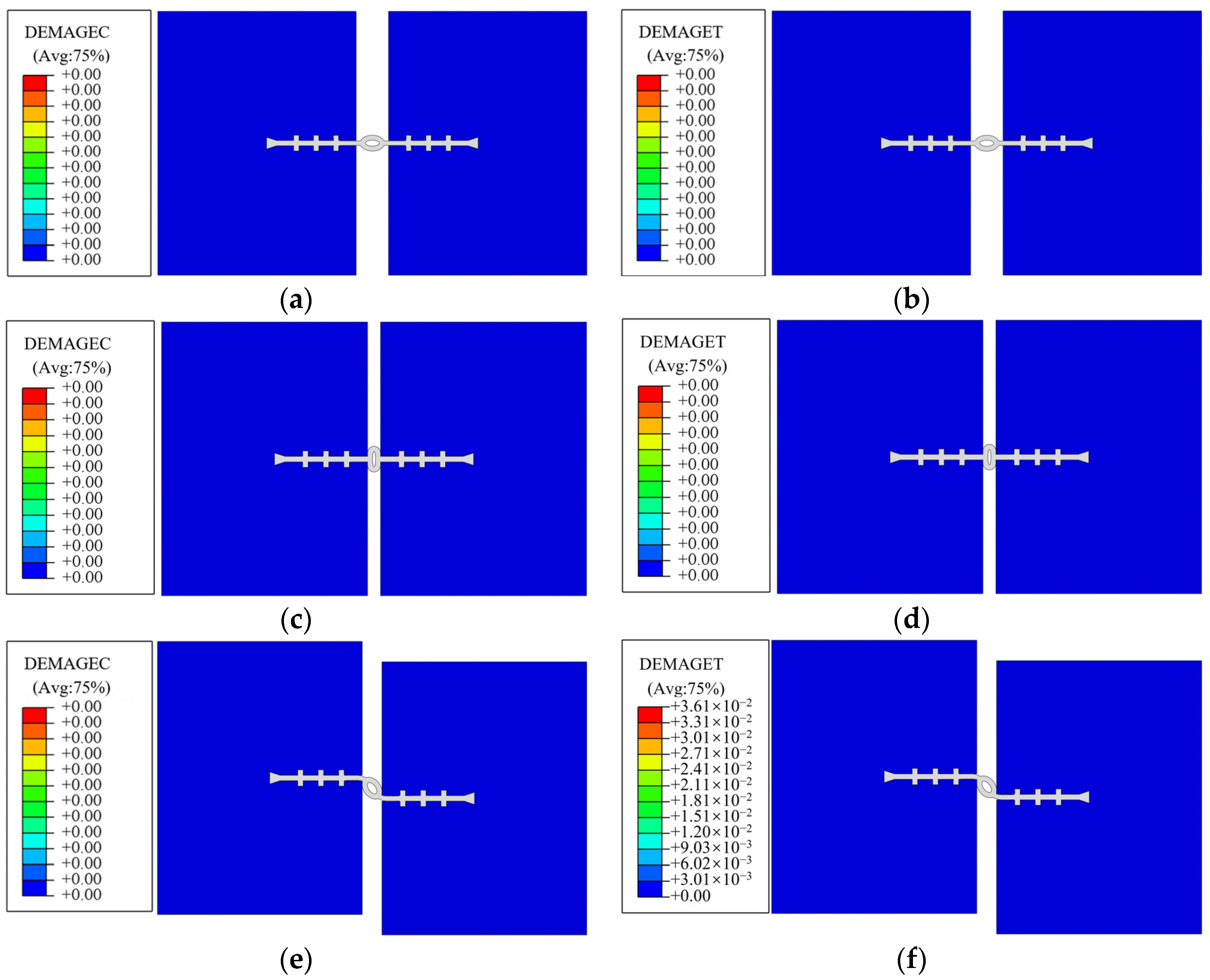
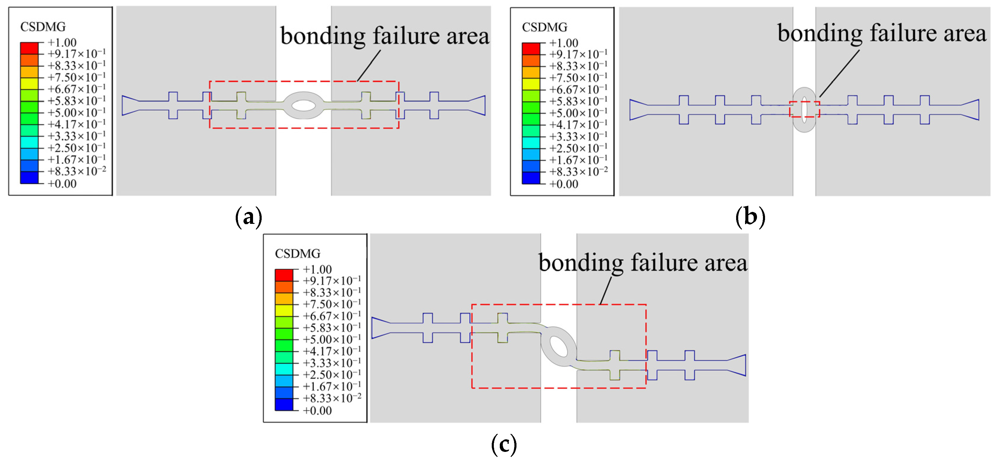
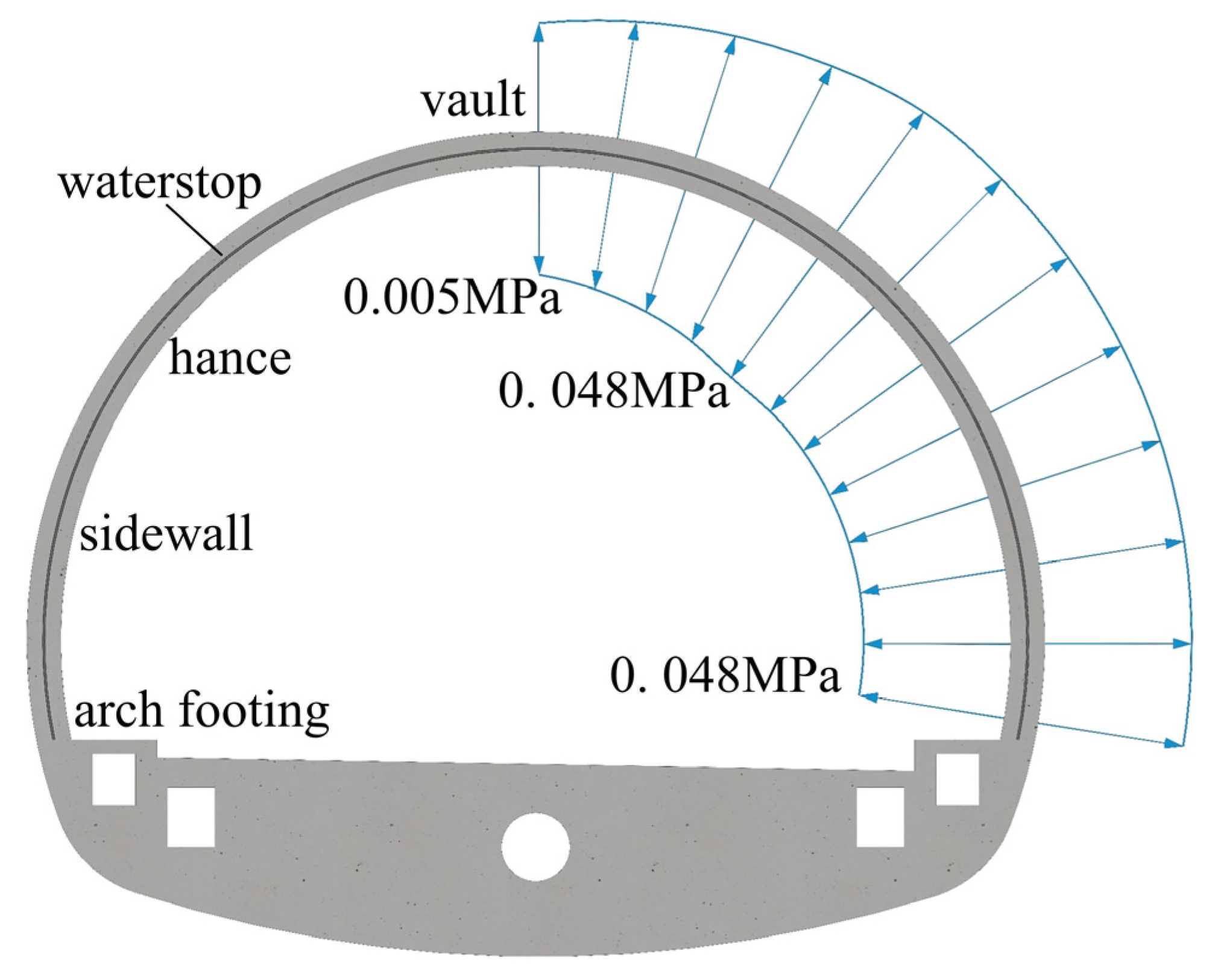
3.2.2. Damage Failure Analysis of Concrete Lining

Taking working condition 1 as an example, Figure 10 shows concrete compression and tensile damage when lining tension, compression, and uneven settlement deformation reach the maximum. DAMAGEC is the concrete compression damage value, and DAMAGET is the concrete tensile damage value. The results show that the damage value of concrete lining in tensile and compressive deformation is 0, the compressive damage value of concrete lining in settlement deformation is 0, and the tensile damage value is approximately equal to 0. It can be considered that the concrete has no plastic damage, which will not be considered in the following.

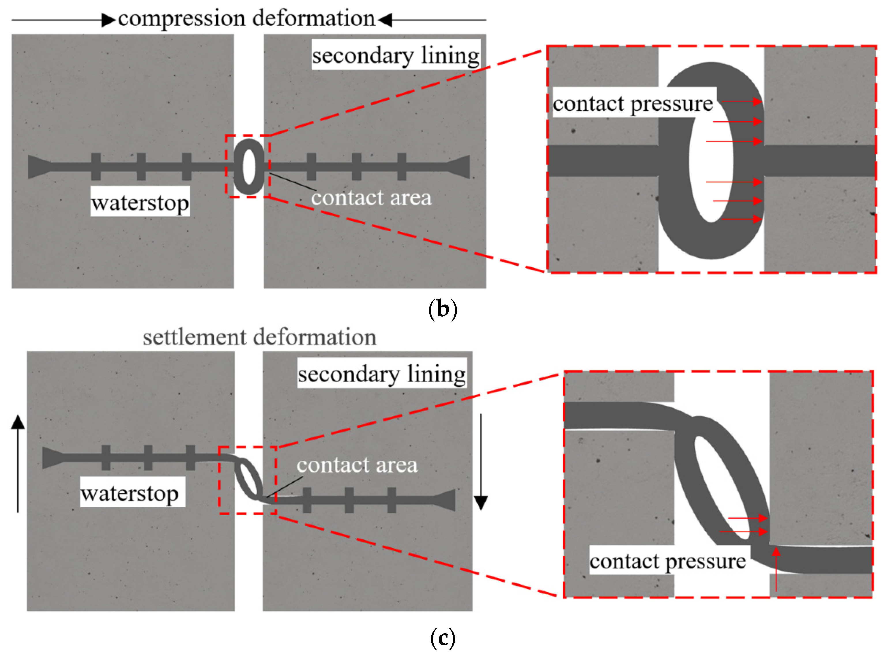
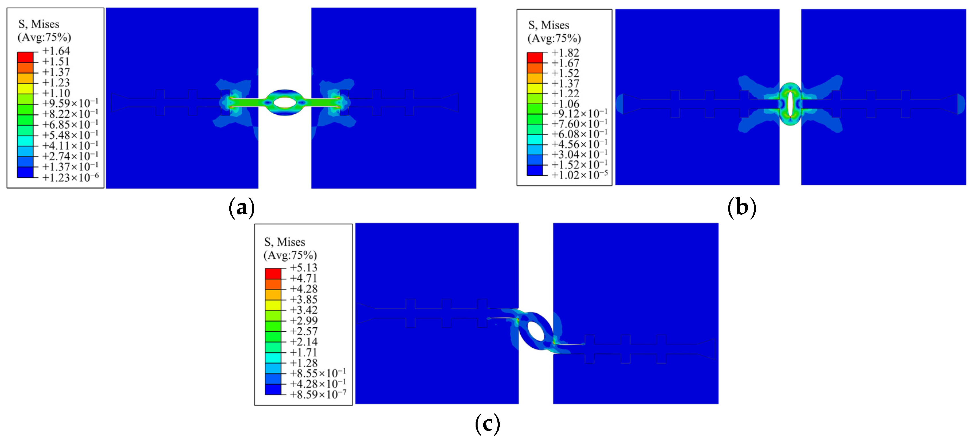
3.2.3. Deformation Stress Characteristics of the Waterstop

Taking operating condition 1 as an example, Figure 11 shows the von Mises stress distribution when the tensile, compressive, and uneven settlement deformation of the lining reaches the maximum. The stress on the waterstop is mainly concentrated between the first rib on the left and right sides during tensile deformation, and the stress on the waterstop during compression deformation and settlement deformation is mainly concentrated in the middle hole of the waterstop, whilst the farther side of the waterstop faces almost no force.
The bond damage between the waterstop and the concrete when the deformation of the lining reaches the maximum is shown in Figure 12, where CSDMG is the bond stiffness damage value. Tensile deformation and settlement deformation inflict greater damage on the bond between the waterstop and the concrete, and the bond failure area is between the second ribs on both sides of the waterstop. However, the damage to the bond by compression deformation is small, and only the bond near the middle hole fails.
It can be seen that: (1) due to the failure of the bonding part after deformation, the short-term resistance of the waterstop belt to seepage is only provided by the deformation contact pressure; (2) deformation will not completely destroy the bond between the waterstop belt and concrete, and joint deformation is uncertainty, so the waterproofing ability of the waterstop belt depends on its resistance to water seepage in the long term; (3) after deformation, the effective seepage path of the waterstop becomes shorter and the reliability of the waterstop as a barrier to leakage decreases. Once the joint is restored from a large deformation to a small deformation, compared with the joint without deformation, the waterproof is more likely to fail.

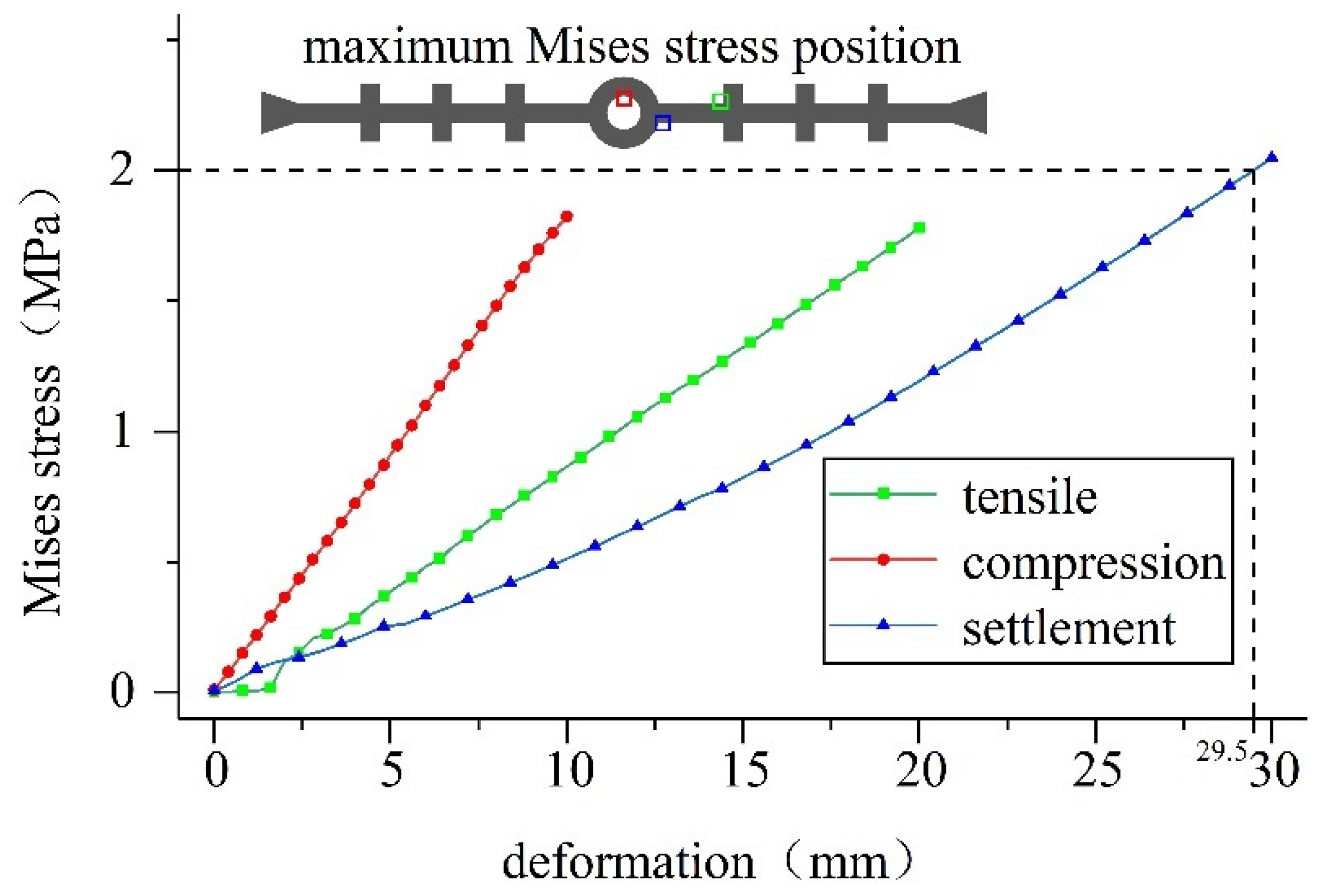
3.2.4. Deformation Stress on the Waterstop

Taking working condition 1 as an example, the development of the maximum von Mises stress on the waterstop with the increase in the deformation is plotted in Figure 13. It can be seen that the overall von Mises stress value on the waterstop increases with the increase in deformation, and is approximately linearly related to the amount of deformation. With different types of deformation, different parts of the waterstop belt become dangerous. Under tensile deformation, the joint between the first rib and the side of the waterstop belt is the most stressed part. Under compression deformation, the upper and lower positions of the inner holes of the waterstop belt are the most stressed parts. Under settlement deformation, the joint between the side wing of the waterstop and the middle hole, and the position not in contact with the lining is the most stressed part.
As can be seen from the figure, under compression deformation, the stress on the waterstop grows the fastest, followed by tensile deformation and settlement deformation. However, due to the difference in deformation, the waterstop is under the maximum stress when the settlement deformation reaches the maximum value. During tensile and compressive deformation, the von Mises stress value of the waterstop is always within the level of 2 MPa. When settlement deformation occurs, once the deformation becomes greater than 29.5 mm, the von Mises stress exceeds the dangerous level, and it is difficult to meet the service life requirements.

3.3. Waterproof Capacity Analysis of the Waterstop

3.3.1. Long-Term Resistance of the Waterstop to Seepage

As shown in Figure 14, the maximum nominal stress criterion is regarded as the damage initiation criterion for the bonding between the waterstop belt and concrete, and the bonding stress is 0.096 MPa according to the test results.
The initial contact pressure can be calculated according to the discussion in the preceding section. According to Equation (2), the long-term resistance of tunnel joints to water seepage is the minimum at the vault, which is 0.101 MPa. Initially, it increases along the lining contour and then remains unchanged, and the maximum value is 0.144 MPa (Figure 15).
Tunnel leakage occurs in the vault, hance, sidewall, and arch footing [34,35]. According to the distribution of the long-term resistance of the waterstop to seepage, the reasons for leakage are as follows: (1) the long-term resistance to seepage at the vault is the smallest in all parts of the tunnel lining. (2) The water pressure increases downward along the lining contour, and the long-term resistance of the waterstop to seepage is the same from the hance to the arch footing. When the water pressure after the lining increases, the water pressure at the sidewall and arch footing will reach the maximum water pressure that the joint can bear first, and then leakage occurs.

3.3.2. Short-Term Resistance of the Waterstop to Seepage

Taking working condition 1 as an example, the development and change of the maximum value of contact pressure of the waterstop with the increase in the deformation are plotted in Figure 16.
Figure 16 shows that the overall contact pressure between the waterstop and the concrete increases with the increase in deformation. During tensile deformation, the connection between the first rib of the waterstop and the flank is the part with the highest contact pressure; during compression deformation, the contact position around the middle hole and the lining is the position with the highest contact pressure; when the settlement is deformed, the contact position between the flanks of the waterstop and the lining is the position with the highest contact pressure.
It can be seen from above that short-term resistance to seepage is offered by the deformation contact pressure. Figure 16 shows that when the tensile deformation is greater than 2.7 mm, the compression deformation is greater than 4.7 mm, and the settlement deformation is greater than 2 mm, the short-term resistance to water seepage is greater than the long-term resistance. Subsequently, with increasing deformation, the short-term resistance to water seepage also continues to increase.
The related results of working conditions 1 and 2 are shown in Table 4, where P wl st is the long-term seepage resistance, the critical deformation tc is the deformation when the short-term seepage resistance is equal to the long-term seepage resistance, Misesmax is the maximum von Mises stress on the waterstop, the allowable deformation ta is the maximum deformation when the hose can meet the service life requirements, and P wl lt max is the maximum short-term seepage resistance within the allowable deformation.
In summary, the following conclusions can be drawn:
(1)
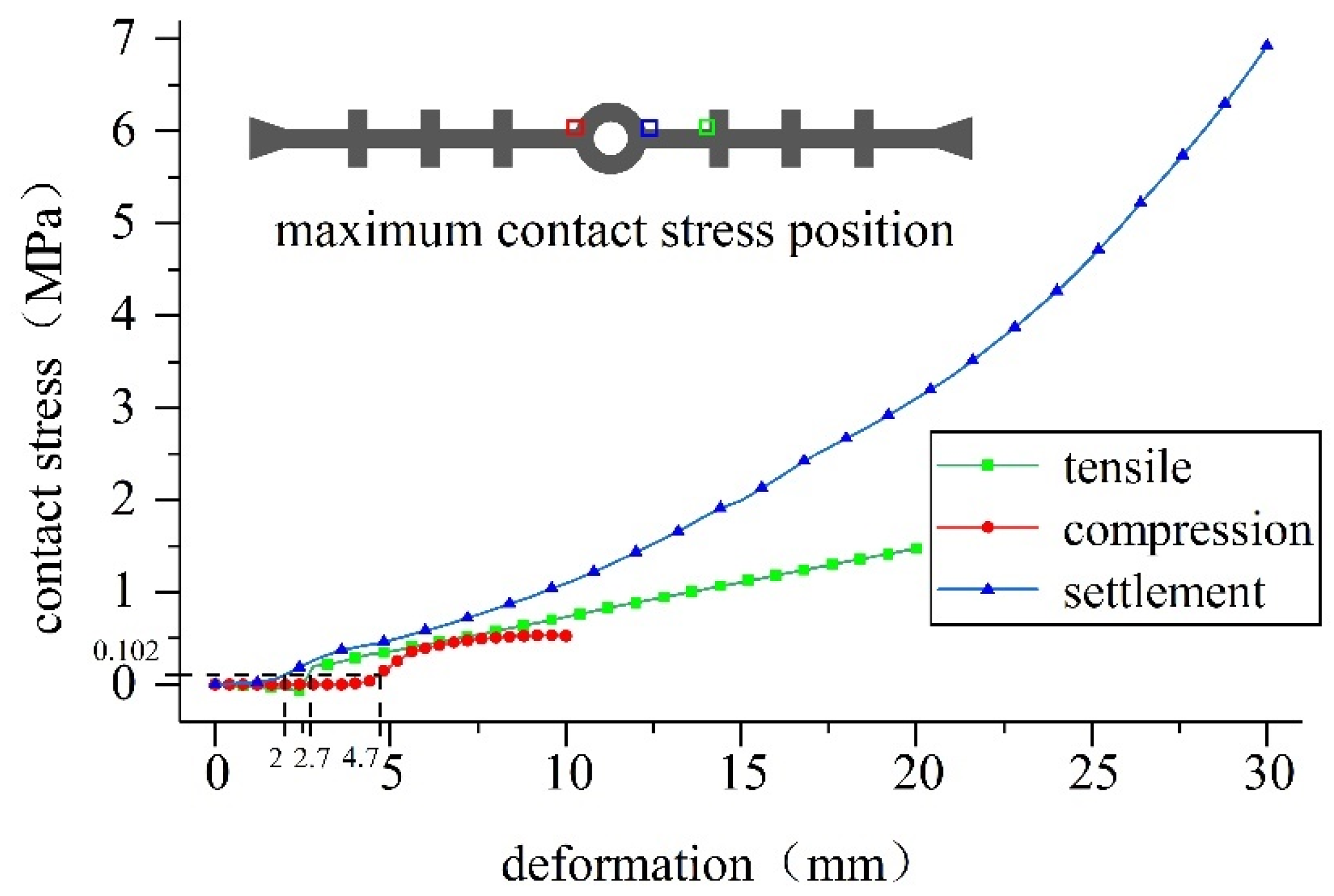
The stress on waterstop I at the maximum tensile and compressive deformation does not reach the dangerous level. After the settlement deformation reaches 29 mm, the stress exceeds the dangerous level, which may make it difficult for the tunnel joint to meet the service life requirements.
(2)
When the deformation of the tunnel joint is greater than the critical deformation, the short-term resistance to water seepage is greater than the long-term resistance to water seepage. Therefore, if the waterstop can maintain a certain amount of deformation for a long time, it may be more conducive to the waterproofing of the tunnel joint.
(3)
Except for the long-term water seepage resistance, the difference between working conditions 1 and 2 is small, which means that the initial contact pressure has little effect on the waterproofing ability of the waterstop after deformation.

4. Optimization Analysis of the Waterproof Performance of the Waterstop

According to the above analysis: (1) The deformation of the waterstop may lead to such a massive increase in stress that it becomes difficult for the tunnel joint to meet the service life requirements. (2) The deformation will cause local damage to the bond between the waterstop and the concrete, reducing its waterproof reliability. (3) The waterproofing of tunnel joints mainly depends on the long-term resistance of the waterstop to water seepage. Therefore, for the waterstop to be effectively waterproof for a long time, it is necessary to improve the stress and deformation state of the waterstop by ensuring good construction quality, and to improve the long-term resistance of the waterstop to water seepage.

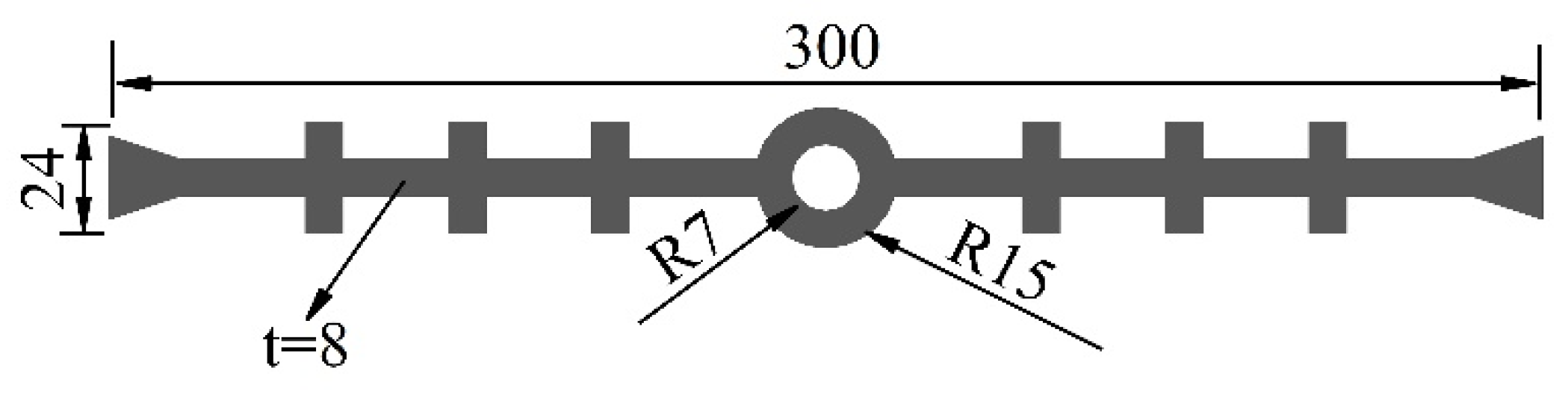
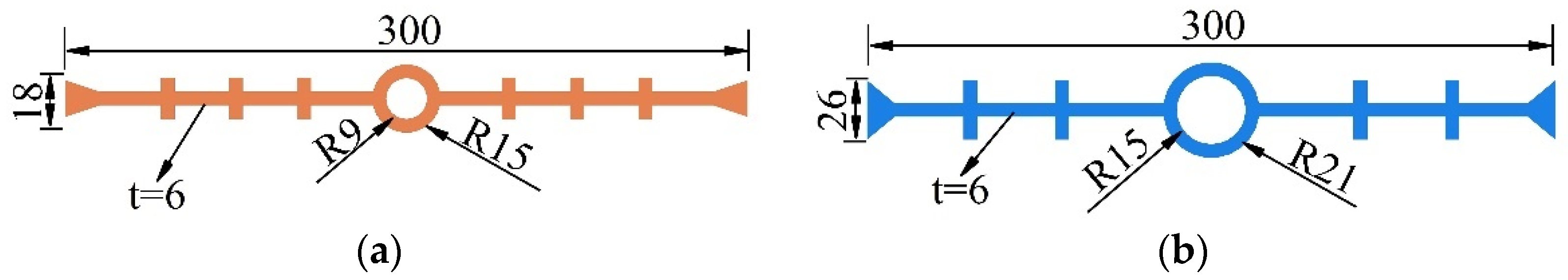
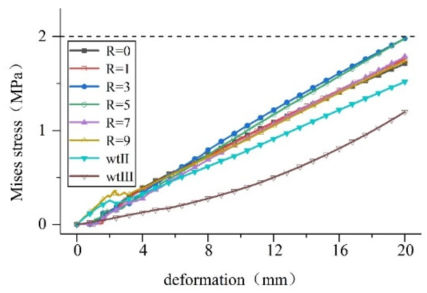
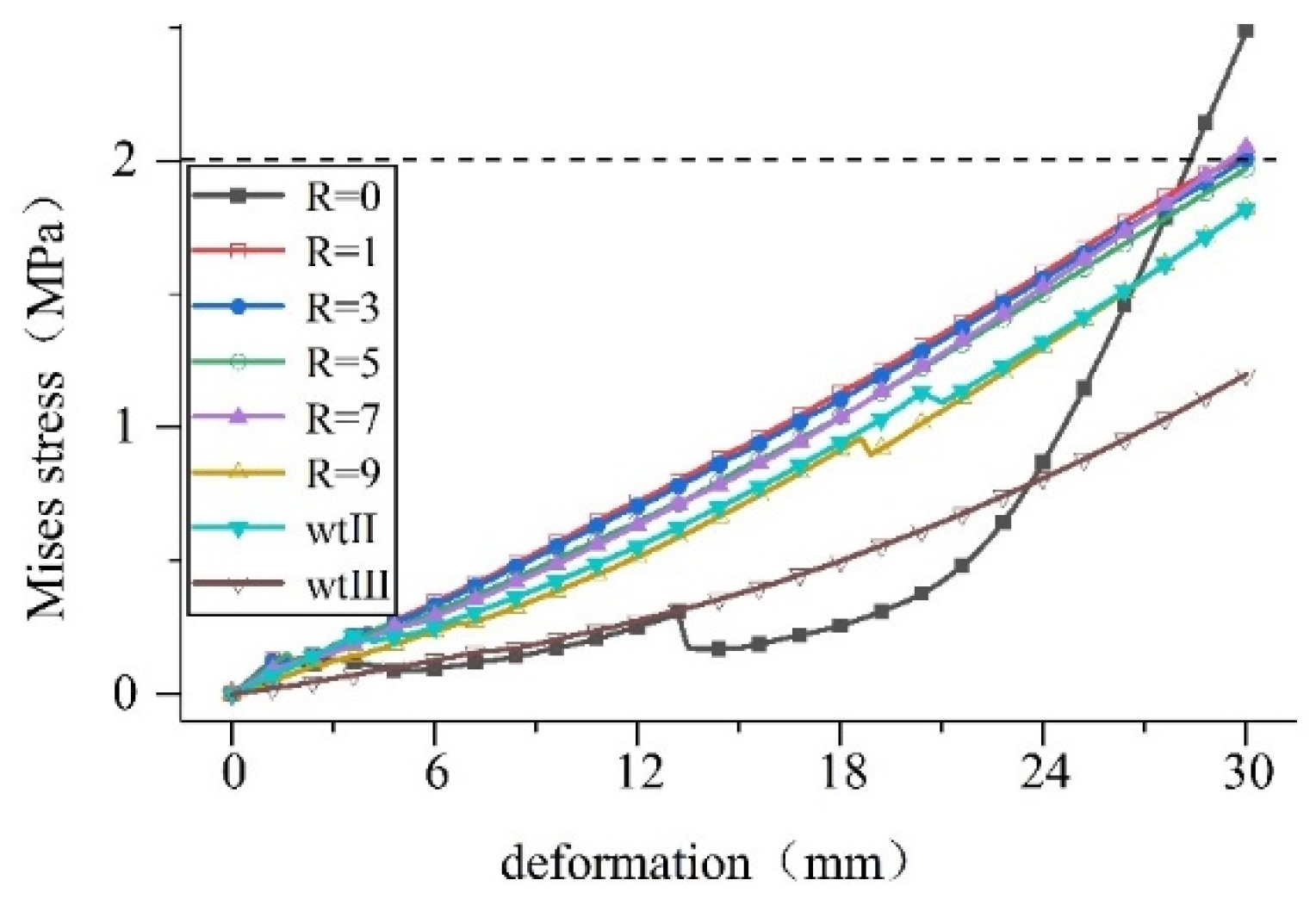
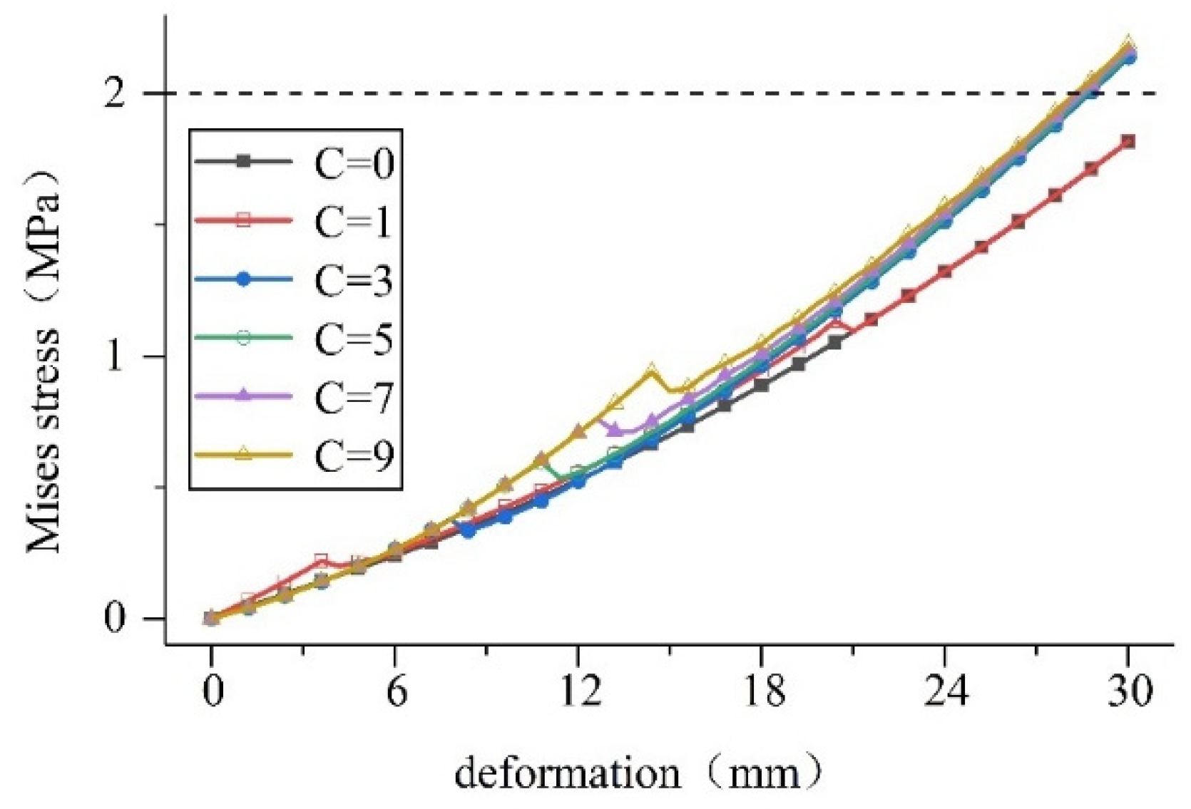
4.1. Dimensional Optimization of the Waterstop

The deformation state of the waterstop can be improved by optimizing the size of the waterstop. At present, there are many specifications for buried waterstops used in tunnels. To compare the influence of the size of the middle hole of the waterstop and the thickness of the waterstop on its deformation, various inner diameters of the middle hole are used for waterstop I. At the same time, specifications and engineering cases are referred to in order to select two types of waterstops. As shown in Figure 17 and Figure 18, waterstop II is thinner than waterstop I, the thickness of waterstop III is the same as that of waterstop II, and the size of the mesopore of waterstop III is larger than that of waterstops I and II. The plane strain finite element models are established.
As can be seen, the concrete has no plastic damage, so it can be treated as a rigid body, and the deformation applied is the same as above. The calculation results obtained are shown in Figure 19, Figure 20 and Figure 21.
Calculations show that: (1) When the middle hole has a specific outer diameter, increasing its inner diameter can improve the stress state during the deformation of the waterstop belt. The compression deformation is more obvious, and the maximum stress value is reduced by 71% when R = 9 compared to that when R = 1. (2) When the middle hole is a specific size, reducing the thickness of the waterstop belt can improve the stress state of the tensile deformation of the waterstop belt. At R = 9, the maximum stress value of waterstop II decreased by 13% compared with waterstop I. (3) Increasing the size of the hole in the waterstop belt can obviously improve the stress state during the deformation of the waterstop belt. Taking the settlement deformation as an example, the maximum stress value of waterstop III decreased by 34% compared with waterstop II.
A waterstop is made of rubber, and if it is too thin, it will increase the risk of damage such as tearing and puncturing. The tunnel deformation joint has as designated width. On the premise of satisfying these two conditions, the above analysis shows that stress deformation can be improved by reducing the thickness of the waterstop and increasing the inner diameter and size of the hole in the waterstop. This will also reduce the damage to the bond between the waterstop and the concrete due to deformation, and reduce the risk of waterstop failure caused by excessive deformation.

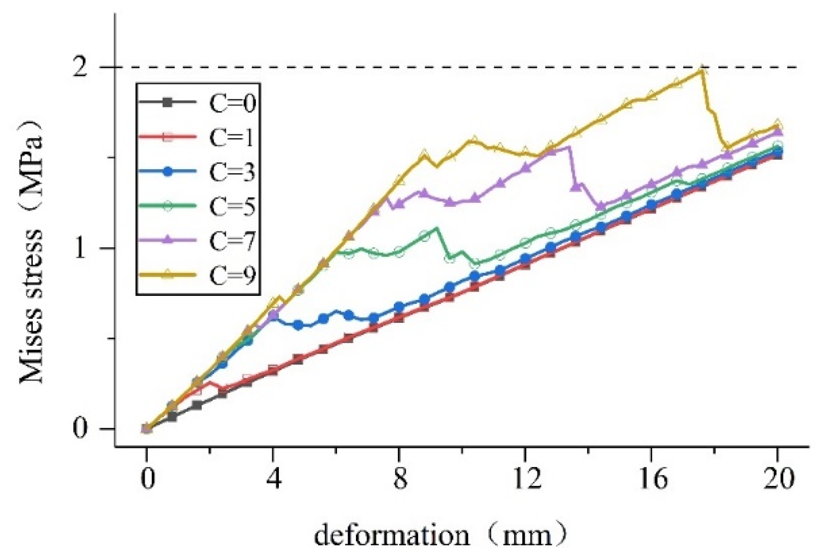
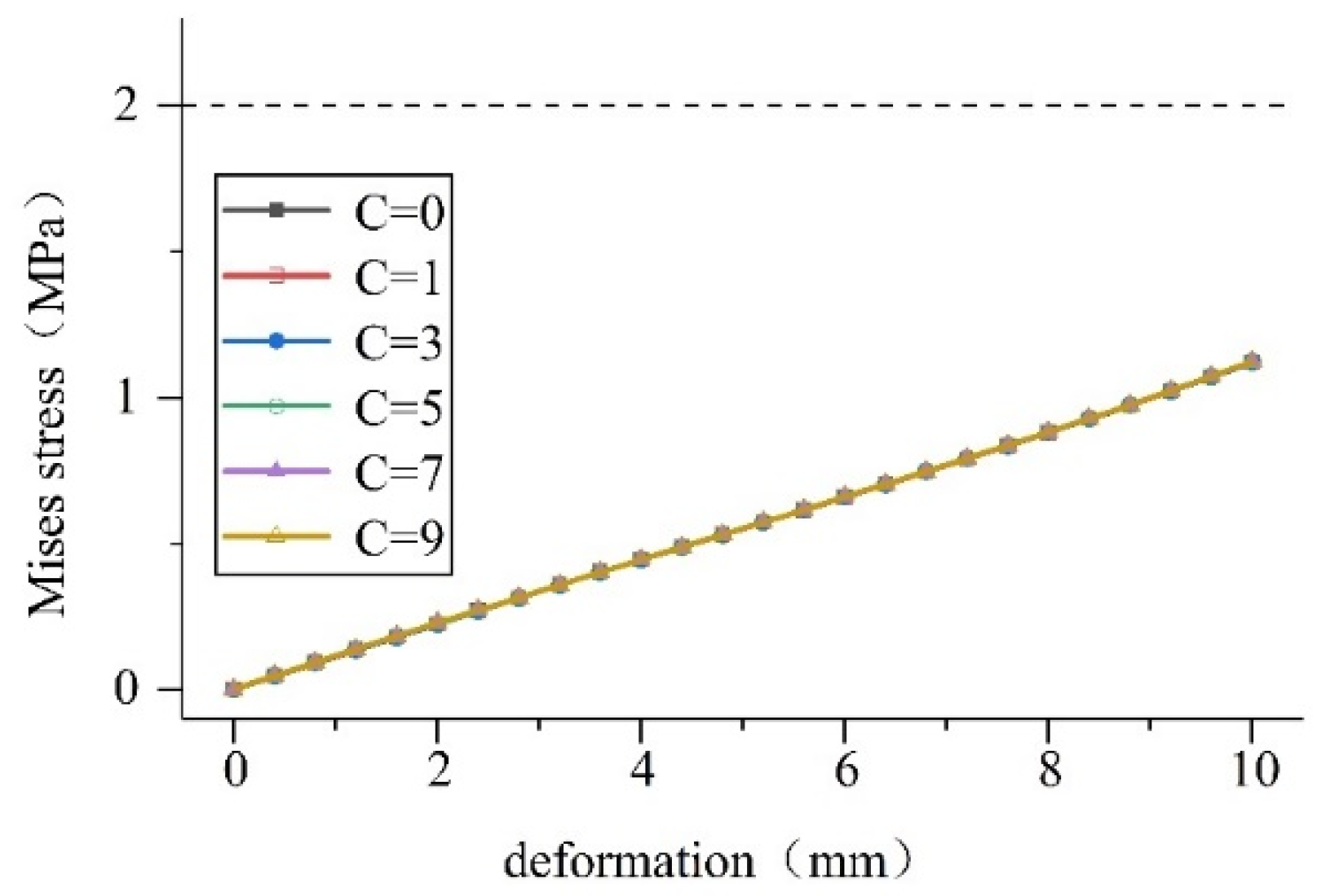
4.2. Optimal Analysis of the Adhesion between the Waterstop and Concrete

The waterproof capacity of the waterstop depends on its surface contact pressure and adhesive force. Because the contact pressure is difficult to change, the waterproof capacity can be optimized by increasing the adhesive force of the waterstop as follows: (1) the surface of the waterstop a double-sided adhesive layer can be affixed, (2) the surface of the waterstop can be coated with strong adhesive coatings, such as epoxy-quartz sand, and (3) by beating or setting grooves in the waterstop surface. There are also different ways to improve the adhesive force of the waterstop. To analyze the deformation state of the waterstop under different bonding forces, the finite element model was established by taking the waterstop II as an example. This can be accomplished by setting the bond force C = 1 between rubber and concrete obtained in the test, setting different bond forces, and applying the same deformation as above. The calculated results are shown in Figure 22, Figure 23 and Figure 24.
The calculation results show that: (1) the size of the adhesive force does not affect the compression deformation stress on the waterstop, and (2) in the case of tensile and settlement deformation, the greater the bond force, the greater the deformation stress on the waterstop and when the bond force reaches a certain degree, the deformation stress exceeds the dangerous level.
To sum up, the bonding optimization of the waterstop and concrete should be limited to a certain range, combined with size optimization, to increase the long-term resistance of the waterstop to water seepage and meet the requirements of service life.

5. Conclusions

Given the current situation with frequent instances of water leakage in mountain tunnels, this paper summarizes the waterproofing mechanism of the middle-buried waterstop, establishes a finite element model considering the bonding and extrusion of the waterstop, and simulates the waterstop. Taking waterstops I, II, and III as examples, the influences of the size, specification, and deformation of the waterstop belt on the waterproof effect is analyzed, and optimization measures for the waterstop belt are put forward. The specific conclusions are as follows:
(1)
The waterproofing ability of the buried waterstop mainly depends on its resistance to seepage, and the resistance involves contact pressure and bonding force between the waterstop and concrete. According to whether the tunnel joint is deformed or not, it can be classified as short-term or long-term seepage resistance.
(2)
The deformation force of the waterstop is mainly concentrated between the first ribs on the left and right sides. The deformation does not completely destroy the bond between the waterstop belt and concrete, but only reduces the waterproofing reliability of the waterstop. Therefore, the waterproofing ability of the waterstop depends on its long-term resistance to water seepage.
(3)
The stress on the waterstop may exceed the dangerous level when the deformation is large, making it difficult for the tunnel joints to meet the service life requirements. For example, the stress on the waterstop I in this paper will exceed the dangerous level after the settlement deformation reaches 29 mm.
(4)
The long-term resistance of the waterstop to water seepage is the smallest at the vault, first increases continuously along with the lining profile and then remains unchanged. When the deformation of the tunnel joint is greater than the critical deformation, the short-term resistance to water seepage is greater than the long-term resistance to it.
(5)
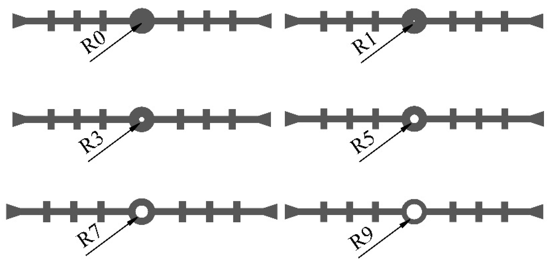
Reducing the thickness of the waterstop and increasing the size of the hole in the waterstop are beneficial to improving the deformation and stress state of the waterstop and to reducing the damage to the bond between the waterstop and the concrete. Increasing the adhesion between the waterstop and the concrete can significantly improve the long-term resistance of the waterstop to water seepage, but at the same time, the deformation stress on the waterstop will increase.

Author Contributions

Conceptualization, Y.W.; methodology, Y.W.; validation, H.W. (Haiping Wu); investigation, H.W. (Haoran Wu); resources, S.F.; data curation, D.C.; writing—original draft preparation, H.W. (Haiping Wu); writing—review and editing, S.F.; visualization, J.Z.; project administration, J.Z. and D.C. All authors have read and agreed to the published version of the manuscript.

Funding

This research was funded by the Department of Transport of Hubei Province Science and Technology Project, grant number 2020-186-2-5.

Institutional Review Board Statement

Not applicable.

Informed Consent Statement

Not applicable.

Data Availability Statement

All data are available from the author.

Conflicts of Interest

The authors declare no conflict of interest.

References

  1. Muhammad, N.Z.; Keyvanfar, A.; Majid, M.Z.A.; Shafaghat, A.; Mirza, J. Waterproof Performance of Concrete: A Critical Review on Implemented Approaches. Constr. Build. Mater. 2015, 101, 80–90. [Google Scholar] [CrossRef] [Green Version]
  2. Sañudo, R.; Miranda, M.; García, C.; García-Sanchez, D. Drainage in Railways. Constr. Build. Mater. 2019, 210, 391–412. [Google Scholar] [CrossRef]
  3. Li, P.; Liu, H.; Zhao, Y.; Li, Z. A Bottom-to-up Drainage and Water Pressure Reduction System for Railway Tunnels. Tunn. Undergr. Space Technol. 2018, 81, 296–305. [Google Scholar] [CrossRef]
  4. Hohmann, R. Fugenausbildung und -Abdichtung Bei Wasserundurchlässigen Bauwerken Aus Beton: Neue Regelwerke Setzen Maßstäbe. Beton-Stahlbetonbau 2004, 99, 938–948. [Google Scholar] [CrossRef]
  5. Song, J.; Oh, K.; Kim, B.; Oh, S. Performance Evaluation of Waterproofing Membrane Systems Subject to the Concrete Joint Load Behavior of Below-Grade Concrete Structures. Appl. Sci. 2017, 7, 1147. [Google Scholar] [CrossRef] [Green Version]
  6. Lv, K.; Ma, C.; Ji, Z.; Xu, P. Development of Butterfly Drainage Waterstop for Tunnel Lining Construction Joint. Mod. Tunn. Technol. 2011, 48, 23–26+37. [Google Scholar] [CrossRef]
  7. Lv, K.; Ji, Z.; Ma, C. Tunnel Construction Joints Back Stick Type Waterstop Technology Several Improvements. Mod. Tunn. Technol. 2012, 49, 39–43. [Google Scholar] [CrossRef]
  8. Liu, Q.; Tan, Z.; Ren, H.; Wang, X.; Xu, R. Study on New Water Stop of New Sea Tunnel. China J. Highw. Transp. 2016, 29, 116–123. [Google Scholar] [CrossRef]
  9. Cho, B.H.; Nam, B.H.; Seo, S.; Kim, J.; An, J.; Youn, H. Waterproofing Performance of Waterstop with Adhesive Bonding Used at Joints of Underground Concrete Structures. Constr. Build. Mater. 2019, 221, 491–500. [Google Scholar] [CrossRef]
  10. Cho, B.H.; Nam, B.H.; Seo, S.; Kim, J.; An, J.; Youn, H. Preliminary Study of Waterstop with Adhesive Bonding Technique for Diaphragm Wall Construction. In Proceedings of the Transportation Research Board 98th Annual Meeting, Washington, DC, USA, 13–17 January 2019. [Google Scholar]
  11. Ma, W.; Guo, X.; Ma, C.; Guo, Y.; Jin, J.; Li, P. Structure Design and Performance Test of Self-Adhesive Waterstop. China Railw. 2015, 30–33. [Google Scholar] [CrossRef]
  12. Guo, X.; Ma, W.; Ma, C.; Guo, Y.; Jin, J.; Chen, S. Model Test Study on Comprehensive Drainage Effect of Self-Adhesive Waterstop. Railw. Eng. 2016, 25–28. [Google Scholar]
  13. Guo, X. Experimental Study on Anchorage Performance of Rubber Waterstop in Railway Tunnel. Railw. Eng. 2017, 57, 49–51. [Google Scholar]
  14. Association of State Dam Safety Officials (Ed.) Association of State Dam Safety Officials Annual Conference 2010, [ASDSO Annual Conference]: Seattle, WA, USA, 19–23 September 2010; Curran: Red Hook, NY, USA, 2011; ISBN 978-1-61782-979-6. [Google Scholar]
  15. Popchenko, S.N.; Stabnikov, N.V. Bituminous Surface Waterstops for Joints of Hydraulic Structures. Gidrotekhnicheskoe Stroit. 1973, 15–18. [Google Scholar]
  16. Laning, A. Flexible Waterstops. Aberd. Concr. Constr. 1993, 38. [Google Scholar]
  17. Kudritz, J.; Adams, R.; Davis, C. Putting the STOP in Waterstops. In Proceedings of the 2017 ASDSO Annual Dam Safety Conference, San Antonio, TX, USA, 10–14 September 2017; Association of State Dam Safety Officials: San Antonio, TX, USA, 2017; pp. 493–501. [Google Scholar]
  18. Wang, W.; Luo, Y.; Kong, L.; Zhang, Y.; Chen, Y. Numerical Simulation and Experimental Study on Mechanical Properties of GINA Waterstop. Mod. Tunn. Technol. 2021, 58, 237–243. [Google Scholar] [CrossRef]
  19. Luo, Y.; Feng, Z.; Liu, J.; He, B.; Guo, H. Research on Structure and Performance of Internal Rubber Waterstop. Railw. Eng. 2013, 93–96. [Google Scholar]
  20. Liu, S.; Xu, Y.; Guo, L.; Wang, Y. Numerical Analysis of Corrugated Waterstop of High CFRDs. Water Power 2019, 45, 28–31. [Google Scholar]
  21. Chen, E.; Chen, K.; Ma, C.; Xin, Y. Finite Element Analysis of Rubber Waterstop Belt under Stress State. World Rubber Ind. 2010, 37, 15–19. [Google Scholar]
  22. Lin, P.; Zhao, Z.; Fan, B.; Han, S.; Liu, G. Analysis of the Deformation Capacity and Size Optimization of Rubber Waterstop in the Deformation Joint of Utility Tunnel. Bull. Sci. Technol. 2020, 36, 57–63. [Google Scholar] [CrossRef]
  23. Meng, C.; Li, R.; Liu, J.; Xu, Y.; Li, J.; Hao, J. Research on Internally-Side Attached Rubber Waterstop Belt: Part I Pull-out Tests of Rubber Strip and Its Numerical Simulation. Water Power 2021, 47, 69–72+95. [Google Scholar]
  24. Li, R.; Meng, C.; Zhou, J.; Xu, Y.; Li, J.; Hao, J. Research on Interally-Side Attached Rubber Waterstop Belt: Part II Numerical Simulation on Waterstop Belt and Its Model Test. Water Power 2021, 47, 42–45. [Google Scholar]
  25. TZ 331-2009; Technical Guide for Construction of Railway Tunnel Drainage. China Railway Publishing Institute: Beijing, China, 2009.
  26. Wang, T. Control of Cracking in Engineering Structure, 2nd ed.; China Building Industry Press: Beijing, China, 2017; ISBN 978-7-112-20690-2. [Google Scholar]
  27. Pu, C.; Xia, C.; Li, Y.; Weng, X. Study of Thermo-Stress of Highway Tunnel and the Law of Line-f Issure Development Caused by the Thermo-Stress. China J. Highw. Transp. 2000, 78–81. [Google Scholar] [CrossRef]
  28. Xue, S. Waterproof Technology of Underground Construction Engineering; China Building Industry Press: Beijing, China, 2003; ISBN 7-112-05904-6. [Google Scholar]
  29. Dong, L.; Jiang, Y.; Yang, Z.; Cheng, J.; Liu, C.; Zhang, J. Experimental Study and Water-Resistant Mechanism of Gaskets in Joints of Tunnel Segments. Chin. J. Geotech. Eng. 2017, 39, 469–474. [Google Scholar]
  30. Gu, G. Mechanical Analysis of Rubber Waterstop Belt and Plastic Waterstop Belt; Chinese Society of Hydroelectric Engineering: Beijing, China, 2004; pp. 399–406. [Google Scholar]
  31. Lee, J.; Fenves, G.L. Plastic-Damage Model for Cyclic Loading of Concrete Structures. J. Eng. Mech. 1998, 124, 892–900. [Google Scholar] [CrossRef]
  32. GB 50010-2010; Code for Design of Concrete Structures. China Building Industry Press: Beijing, China, 2015.
  33. Gent, A.N. (Ed.) Engineering with Rubber: How to Design Rubber Components, 3rd ed.; Hanser Publishers: Munich, Germany; Cincinnati, OH, USA, 2012; ISBN 978-3-446-42764-8. [Google Scholar]
  34. Zou, Y.; He, C.; Zhou, Y.; Zhang, Z.; Fu, J. Statistics and Cause Analysis of Leakage Diseases in Operating Expressway Tunnels in Chongqing. J. Highw. Transp. Res. Dev. 2013, 30, 86–93+101. [Google Scholar]
  35. Chen, J.; Liu, X.; Zhang, W.; Zhang, J. Investigation and Statistical Analysis of Water Leakage in Highway Tunnel in Guizhou Province. Mod. Tunn. Technol. 2011, 48, 7–11. [Google Scholar]
Figure 1. Schematic diagram of the waterproof structure of the mountain tunnel joints. (a) Deformation joint, (b) Construction joint.
Applsci 12 05737 g001
Figure 3. Water infiltration resistance of tunnel joints.
Applsci 12 05737 g003
Figure 4. The deformation contact pressure of the waterstop. (a) Tensile contact pressure. (b) Compressive contact pressure. (c) Settling contact pressure.
Applsci 12 05737 g004aApplsci 12 05737 g004b
Figure 5. Waterproofing mechanism of the waterstop. (a) Tensile specimen. (b) Shear specimen.
Applsci 12 05737 g005
Figure 6. The tension machine.
Applsci 12 05737 g006
Figure 7. The initial contact pressure of the waterstop.
Applsci 12 05737 g007
Figure 8. Waterstop I (unit: mm).
Applsci 12 05737 g008
Figure 9. Finite element analysis model.
Applsci 12 05737 g009
Figure 10. Damage cloud diagram of concrete stiffness in working condition 1. (a) 1-1 concrete compression damage. (b) 1-1 concrete tensile damage. (c) 1-2 concrete compression damage. (d) 1-2 concrete tensile damage. (e) 1-3 concrete compression damage. (f) 1-3 concrete tensile damage.
Applsci 12 05737 g010
Figure 11. Condition 1 von Mises stress cloud diagram (unit: MPa). (a) 1-1 stress cloud diagram. (b) 1-2 stress cloud diagram. (c) 1-3 stress cloud diagram.
Applsci 12 05737 g011
Figure 12. Damage cloud diagram of bonding stiffness in working condition 1. (a) 1-1 bonding stiffness damage. (b) 1-2 bonding stiffness damage. (c) 1-3 bonding stiffness damage.
Applsci 12 05737 g012
Figure 13. Maximum Mises stress on the waterstop in working condition 1.
Applsci 12 05737 g013
Figure 14. The adhesive force of the waterstop.
Applsci 12 05737 g014
Figure 15. Long-term resistance of the waterstop to seepage.
Applsci 12 05737 g015
Figure 16. The maximum contact pressure of the waterstop in working condition 1.
Applsci 12 05737 g016
Figure 17. Waterstops I with different inner diameters of the middle hole (unit: mm).
Applsci 12 05737 g017
Figure 18. Dimensions of waterstops II and III (unit: mm). (a) waterstop II. (b) waterstop III.
Applsci 12 05737 g018
Figure 19. Tensile deformation stress on waterstops of various sizes.
Applsci 12 05737 g019
Figure 20. Compression deformation stress on waterstops of various size.
Applsci 12 05737 g020
Figure 21. Settlement deformation stress on waterstops of various size.
Applsci 12 05737 g021
Figure 22. Tensile deformation stress on the waterstop under different bonding force conditions.
Applsci 12 05737 g022
Figure 23. Compression deformation stress on the waterstop under different bonding force conditions.
Applsci 12 05737 g023
Figure 24. Settlement deformation stress on the waterstop under different bonding force conditions.
Applsci 12 05737 g024
Table 1. The bonding strength of rubber to concrete.
Conditions123Bonding Strength/MPa
Tensile specimen0.0910.1010.0970.096
Shear specimen0.2150.2080.2110.211
Table 2. Uniaxial stress–strain relationship of concrete.
σc ε c i n σt ε t i n
14.07002.0300
20.1000.0008022.0100.000028
14.6370.0024561.2320.000149
10.0730.0040800.8490.000257
7.5010.0056380.6610.000359
5.9310.0071620.5480.000458
4.8900.0086680.4730.000556
4.1530.0101650.4190.000653
3.6070.0116550.3780.000749
3.1860.0131410.3460.000846
Table 3. Working conditions of finite element analysis.
Working ConditionsInitial Contact Pressure (MPa)Deformation TypesDeformation (mm)
1-1 Tensile20
1-20.005Compression10
1-3 Settlement30
2-1 Tensile20
2-20.048Compression10
2-3 Settlement30
Table 4. Waterstop I waterproof capability parameters.
Conditions P w l s t (MPa)tc (mm)Misesmax (MPa)ta (mm) P w l l t max (MPa)
1-1 2.71.7820.01.48
1-20.1014.71.8210.00.53
1-3 2.02.0529.56.92
2-1 3.11.7520.01.45
2-20.1444.71.8910.00.51
2-3 1.42.0029.96.61
Publisher’s Note: MDPI stays neutral with regard to jurisdictional claims in published maps and institutional affiliations.

