1. Introduction
Electroencephalography (EEG) is a technique used to track the electrical activity of the brain by placing electrodes on the scalp. Clinically, EEGs are often used to identify seizures, but the same technology can also be used by scientists to discover different functions of the brain and how those functions relate to human cognition and behavior. The scalp electrodes used during an EEG are only used to record the brain’s natural electrical activity. Consequently, there is no greater risk associated with this completely non-invasive brain monitoring technique. Most of the signals recorded are likely to come from neurons that are affected by a lot of bioelectric phenomena, such as action potentials, post-synaptic potentials (PSP) and the phenomenon of long-term depolarization of the neuron. Action potentials are associated with a short-term (10 ms or less) local current flow in the axon and a very limited potential field. This makes them unlikely to underlie electroencephalographic phenomena. PSPs last much longer (50–200 ms) and have a much larger electric field. Thus, they are more likely to become major EEG generators. In a healthy brain, the activation potential of a neuron is conducted along the axon to the end of the nerve, where neurotransmitters are released. However, it is the synaptic potential that is the most important source of the electroencephalogram [
1,
2,
3,
4,
5,
6,
7].
EEG is widely used in research involving biomedical engineering, neuroscience and others (e.g., BCI), as well as in sleep analysis and detecting brain abnormalities. The reasons for this are, among others, it is non-invasive and incurs relatively low financial costs. In view of the above facts, the classification of these signals is an important step towards making the use of EEG more practical in use and less dependent on trained professionals [
6,
8,
9,
10].
Electromyography (EMG) is a type of electrophysiological test that records the electrical impulses that are generated by muscle activity. In neuromodulation studies, EMG is often used to measure the various effects of stimulation in the motor regions of the brain. In clinical settings, EMG is often used to diagnose nervous and muscular disorders. Thanks to this method, it is possible to assess where the pathologies are located and check their nature. In the clinics, EMG may involve inserting a small needle into the muscles to register electrical activity. In biomedical engineering, researchers more frequently use only surface electrodes, which are placed on the skin to record the electrical activity generated by the muscles under study. Thus, the EMG becomes completely non-invasive and does not pose any health risks [
6,
11,
12].
Myoelectric interfaces are also used in rehabilitation technology as an auxiliary device. The EMG signal is one of the biological signals that is commonly used to predict human motor intentions and can be used as part of human–robot collaboration systems. These signals, generated in muscle fibers, have also become the subject of much research because they provide a lot of information for the evaluation of neuromuscular diseases, in particular amyotrophic lateral sclerosis (ALS) [
10,
13,
14,
15,
16].
BCI is a technology that allows direct communication between the brain and an appropriate external device. The aim of research on the brain–computer interface is, inter alia, the improvement or repair of human senses or motor activities. EEG signal analysis contributes to the research of BCI technology, which has been successfully covered in various scientific articles [
17,
18].
BCI solutions could revolutionize the way people communicate with computers and other devices in the future. They currently have particular application and practical value in systems that use EEG as a means of communication and control for people with physical disabilities. More and more often we can create algorithms by which it is possible to convert the image of movement into a control or executive signal, which a computer or other microprocessor system gives to various types of devices, such as robots or neurogaming programs [
5,
15,
18,
19,
20,
21,
22].
In [
23,
24], the authors reviewed various types of classification algorithms, used in the design of BCI systems. They are mostly based on the measurements of EEG signals. According to the knowledge conveyed in the works, such algorithms can be divided into four main categories: adaptive classifiers, matrix and tensor classifiers, transfer learning and deep learning, and other classifiers.
This article presents research that was based on the analysis of not only the EEG signal but also the EMG. The literature contains research on the subject of simultaneous use of the properties of measurements of these signals.
The article [
10] presents a rehabilitation technique based on the exoskeleton of the lower extremities integrated with the human–machine interface (HMI). It was used to record and process multimodal signals collected using the brain–machine interface (BMI) based on foot motor imagery (MI) and multichannel electromyographic (EMG) signals recorded from the leg muscles. The investigated system was tested on healthy people operating the exoskeleton under various conditions. The tests show that it is possible to analyze up to 15 signals simultaneously in real time during the movement. The MI of the foot is extracted from the EEG signals (seven channels) using the event-related (de)synchronization effect. The whole is complemented by the cooperation of the aforementioned EEG signal with EMG measurements. They represent the intention to move, the control system can initiate and differentiate right and left leg movement with a high degree of reliability.
The analysis of the coupling of electroencephalogram signals with electromyography in stroke has been successfully presented in [
25]. Taking advantage of the knowledge that the couplings between EEG and EMG signals during motion control reflect the interaction between the cerebral motor cortex and muscles, an approach named variable scale symbolic transfer entropy (VS-STE) analysis was proposed. Post-stroke patients and healthy volunteers participated in studies involving motor skills (e.g., grasping with the hands). The proposed VS-STE was used to evaluate the strength of the cortical–muscular coupling. This coupling therefore occurred between the EEG signal measured from the motor cortex and the EMG signal measured from the upper limb in both the time and frequency domains. The results of the studies showed a greater potency of the bidirectional (EEG-to-EMG and EMG-to-EEG) VS-STE in stroke patients compared to healthy controls.
In [
26], the possibility of using EMG to detect the intention to extend the arm/wrist was tested. This was to launch robot-assisted training for people without residual movements. Detection of movement intent with the EMG detector was compared to the EEG-BCI sensorimotor rhythm using only the ipsilesional activity. The achieved results have shown that it is possible to use EMG to detect the intention to move with a serious impairment of motor abilities. The probability of detecting EMG when the patients tried to move was higher than at rest. Many patients had strong EMGs in the finger/wrist extensors. It can be seen in the conclusions that some severely affected patients may benefit from EMG-based assisted therapy. Compared to the EEG, the EMG interface requires less preparation time, which is easier to use and maintain, and has a more compact size.
In [
27], authors investigated hybrid BCIs, coupling joystick data, EEG and EMG in the case of severe motor disabilities. The method of data processing and classification to detect right and left hand movements is presented. The EMG modality is well suited to patients with Duchenne Muscular Dystrophy (DMD). The reason for this is that less force is needed to detect movements, unlike in the case of conventional interfaces (e.g., joysticks).
In [
28], authors proposed a Recurrent Neural Network (RNN) for performing trajectory control of redundant robot manipulators, using Remote Center of Motion (RCM) constraints. The proposed solution was based on artificial intelligence algorithms. They can be used, for example, in surgical operations. Demonstration experiments, the purpose of which were to verify the correct functioning of the project, were carried out in a laboratory environment using the KUKA LWR4+ robot.
Systems identifying and classifying various conditions, diseases, elements of nature and even those responsible for automatic control of objects have been used successfully for many years. Many of them are increasingly based on artificial intelligence encompassing neural network algorithms.
An effective review of research on the use of convolutional neural networks as a skin cancer classification system is presented in [
29]. In turn, [
30] contains a broad description of the system in which the deep hybrid neural network is used in the task of classifying the histopathological images of breast cancer. In [
31], a new hybrid, convolutional and recurrent deep neural network was designed for classification purposes. The deep plexus network was also used in the classification system to diagnose various disease states. Neural networks are also widely used in the regulation of automation systems, and an example can be seen in [
32,
33], which proposed an artificial intelligence algorithm based on neural nets in the task of controlling a magnetic levitation object, and a robot. These, and many other applications, encourage further research and the expansion of applications of this type of project.
As in [
5], the Emotiv EPOC Flex Gel set was again chosen. It is a comfortable, wireless BCI headset, which provides many possibilities of use and wide application in numerous projects [
34]. It has 32 electrodes, but only some of them were used for the purposes of the study. Research and projects using this kit are very rare, despite its advanced design. The use of Emotiv EPOC Flex took place, among others, in the work on comparing the effect of smoothing filters on the quality of data recorded with the Emotiv EPOC Flex BCI headset during sound stimulation [
35]. It was also used in a pilot article that precedes this study and is less advanced [
5]. Other kit-based research is included in the article on a Brain Computing Training System for Motor Imagery [
36] and a publication on EEG-based eye movement recognition [
37,
38,
39,
40].
Currently, the nomenclature presents the following EEG frequency determination, where the Greek letters are used: Alpha (8–12 Hz), Beta (13–30 Hz), Delta (<4 Hz), Gamma (>30 Hz), Theta (4–7 Hz) and Mu (8–12 Hz). The latter are closely related to brain activity and performance, and are also somewhat similar to alpha waves [
35,
41,
42,
43,
44].
The aim of the conducted research was to design an EEG signal classification system in controlling a mobile robot with simultaneous verification of pure mental commands using a sensor measuring the EMG signal. This is absolutely crucial, as paralyzed people can control objects only with their thoughts, without the additional support of limb muscle movements. After analyzing the literature, it can be concluded that the proposed approach is original.
Building on the previous [
5] pilot study and its successful results, a method of filtering the raw signal followed by periodic signal integration was designed and tested. The data obtained in this way was classified by an artificial neural network. In the current approach, it is only part of the entire expert system. This is to make the algorithm more noise-resistant and simplify its handling. In the current approach, the user only controls the robot by imagining the movement of the arm. Switching the control command to the right and left is done by causing the artifact in the EEG signal in the form of a blink of the right and left eye, respectively. After inducing this state, each subsequent mental command to move will go in the chosen direction. We will return to moving forward (the initial state) by blinking both eyelids at the same time.
The obtained data allowed to control the constructed LEGO Mindstorms EV3 robot. The conducted research can find many applications, because their use is possible in the design of wheelchair assist systems. The next chapter contains a detailed description of the designed system with its individual components.
2. Presentation of Components and Methodology
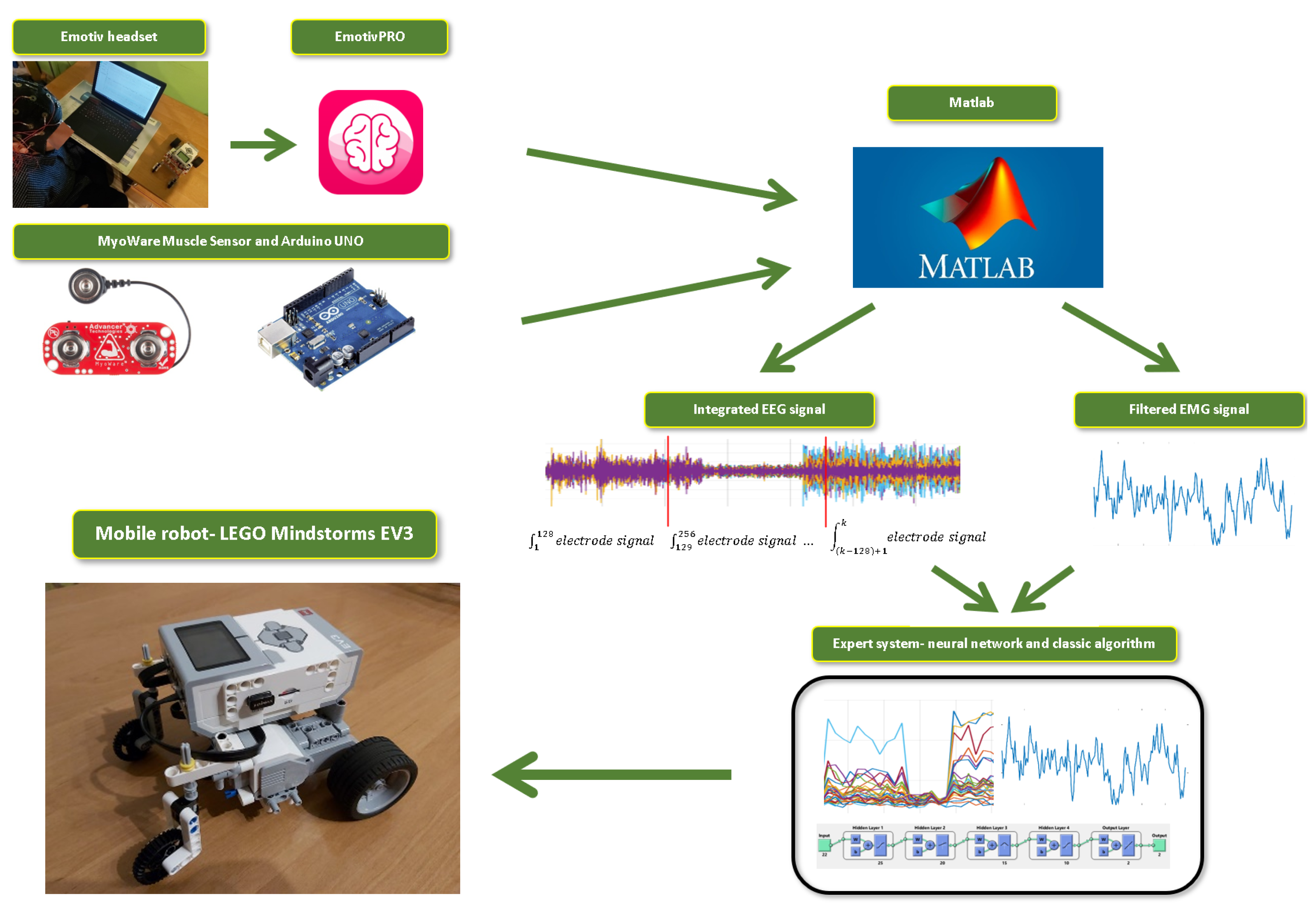
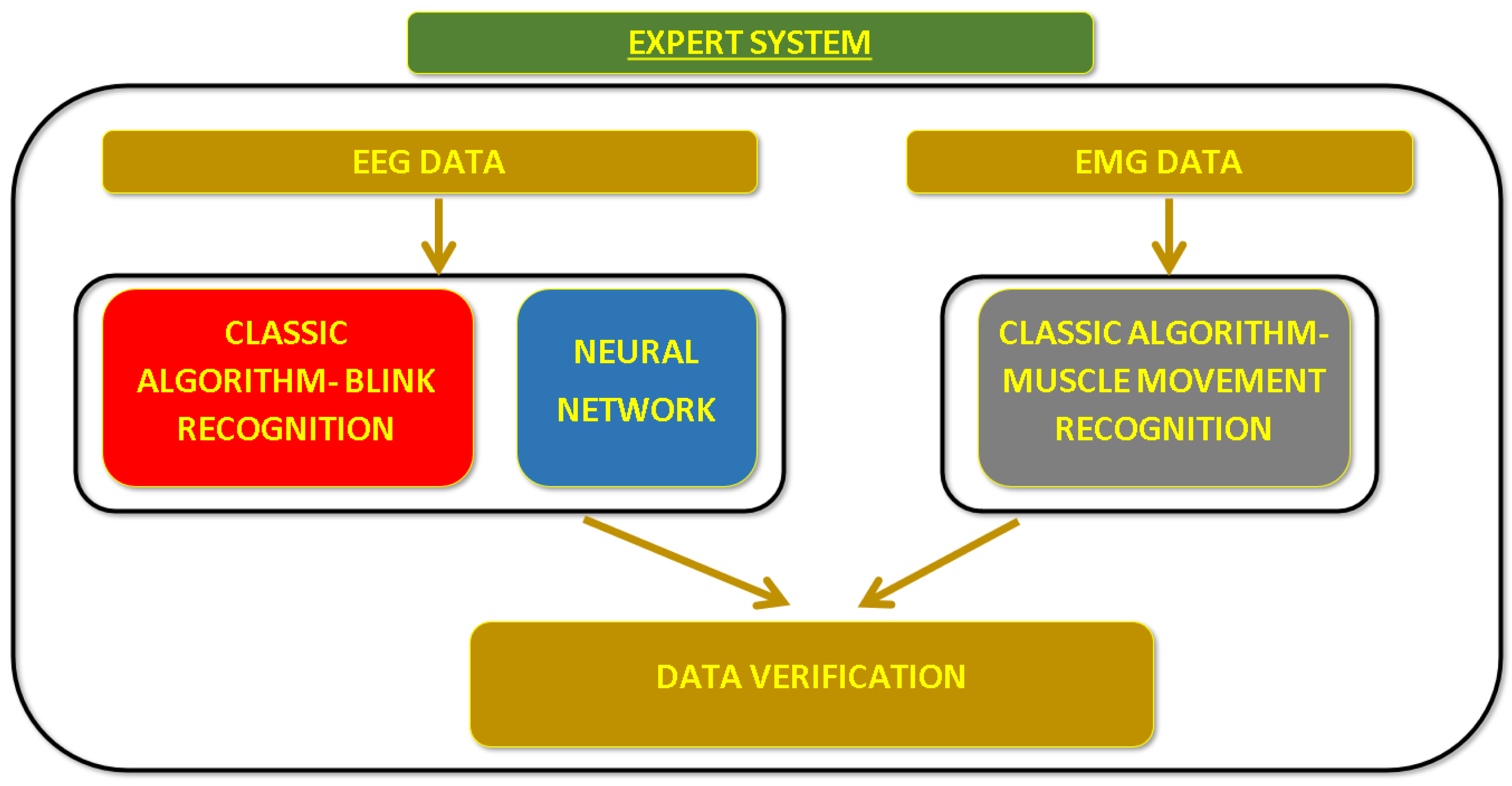
The structure of the analysis and classification system of EEG and EMG signals presented in this paper consists of many elements. The raw EEG signal was recorded with Emotiv EPOC Flex Gel. The acquisition of measurements was performed with the dedicated EmotivPRO software. The EMG signal, in turn, is acquired using the MyoWare Muscle Sensor device, which is connected to the Arduino UNO. This set was in turn synchronized with the Matlab program, in which the measured data was collected and stored.
Both signals (EEG, EMG) are analyzed by an expert system consisting of artificial intelligence algorithms in the form of a neural network and a classic algorithm for detecting artifacts and stimulating the arm muscles. The form of the discussed system is shown in
Figure 1.
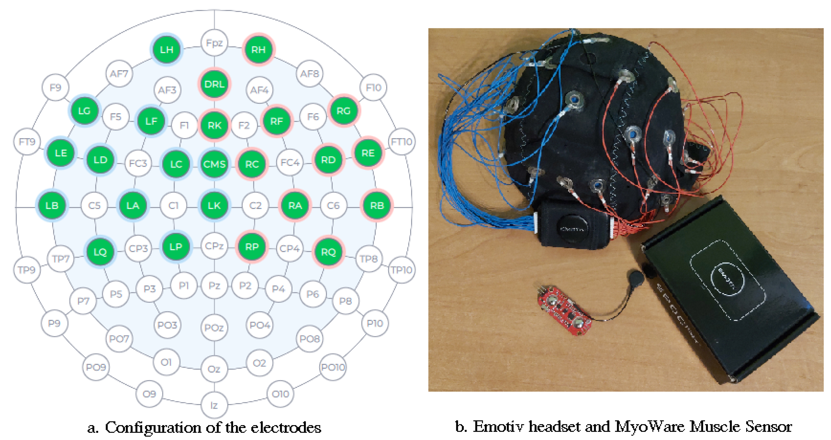
Figure 2 shows the electrode configuration in the Emotiv EPOC Flex Gel headset. Due to the fact that the purpose of the research is to test signals from the area of the motor cortex, it was decided to use only 22 electrodes. The remaining ones were omitted in the EmotivPRO software and thus the EEG signal transmitted to the Matlab environment came from only 22 channels.
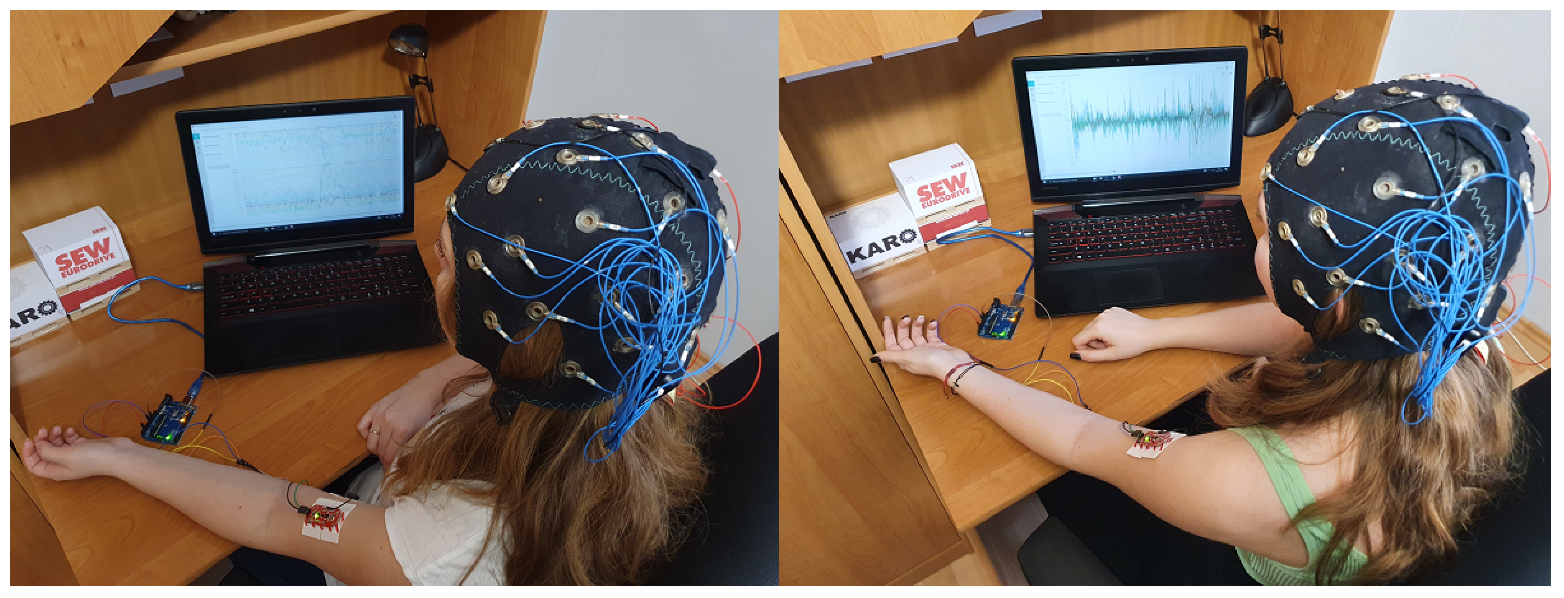
An exemplary form of the conducted research is shown in
Figure 3, which shows the moment of EEG and EMG signal measurements by two study participants. The total number of people surveyed was 10. This number of participants surveyed allows us to efficiently assess the effectiveness of the algorithm and, above all, to design it with a specific resistance to fluctuations in measurement values that depend on people.
The 22 electrodes in the Emotiv EPOC Flex Gel device are named according to the following channel names: Cz-LK, Fz-RK, Fp1-LH, F7-LG, F3-LF, FC1-LC, C3-LA, FC5-LD, FT7-LE, T7-LB, CP5-LQ, CP1-LP, CP2-RP, CP6-RQ, FT8-RE, FC6-RD, C4-RA, T8-RB, FC2-RC, F4-RF, F8-RG and Fp2-RH. The sequence of the mentioned electrodes with the names of the channels in a graphic form is presented in the
Figure 2. The remaining 10 electrodes remained physically connected to the device, but were not used in the manufacturer’s software.
Each of the test members took 15 measurements of the repetitive sequences of mental commands contained. The measurement consisted of the following sequences, each lasting a few seconds: neutral state, imagining the arm movement (mental command—moving the mobile robot), blinking the right eye (from now on, any movement command will result in the robot moving to the right), imagining the arm movement, blinking the left eye (from now on, any movement command will result in the movement of the robot to the left), image of the arm movement, blink both eyes (return to the initial state, each next image of the arm movement is to mean the order to move the robot forward), image of the arm movement. Due to this sequence of actions, the signals collected as a result of the measurements lasted about 45 s.
At the same time as the EEG measurement was taken, the participant in the study had the MyoWare Muscle Sensor device applied to their bicep muscle. This allowed for the efficient collection of the EMG signal, which later gave the possibility of verification regarding pure mental commands without the support of additional muscle movements. Paralyzed people do not have the possibility of such movements, so research into a system that uses only real mental commands based on the image of arm movement is extremely important and worth developing.
The test participants were also asked to maintain the highest possible level of concentration. Its absence would disrupt the course of the research, and thus incorrect results would be achieved. After collecting an appropriate number of measurements, it was possible to further process and classify them using artificial intelligence and classic algorithms, which is described in detail in
Section 5.
5. Presentation of Expert System Based on the Various Algorithms
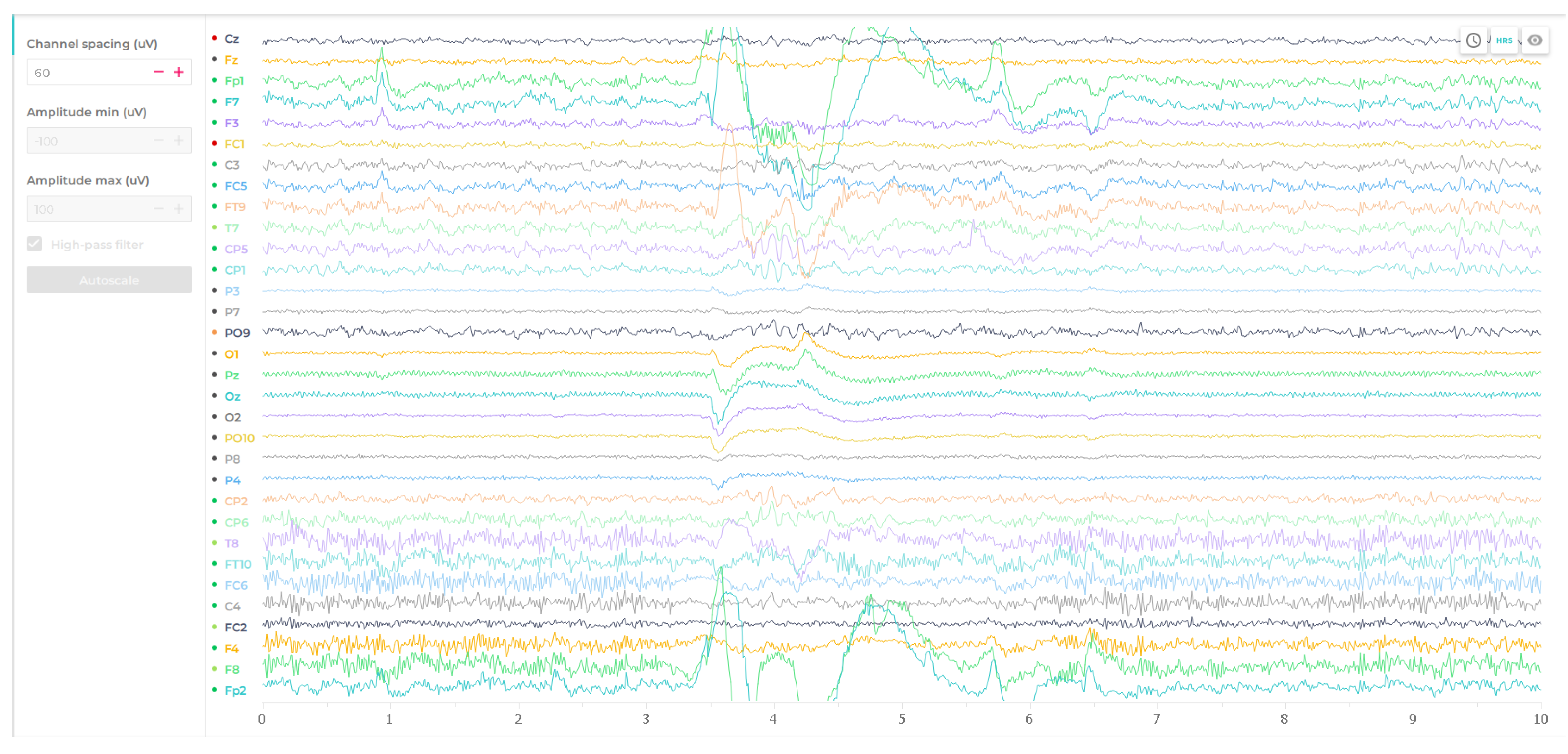
EmotivPRO offers highly advanced solutions for the archiving of raw EEG signal. The user can easily export it and check its features and properties with any other software.
Figure 16 shows the appearance of the desktop offered by the dedicated software EmotivPRO for the Emotiv kit.
In the case of continuation of the research proposed in this approach, all analyses and classification methods were again performed on a programming and numerical computing platform, which is Matlab. An expert system was also designed there, including classic algorithms and an artificial neural network. The scheme of the system’s operation is presented in
Figure 1.
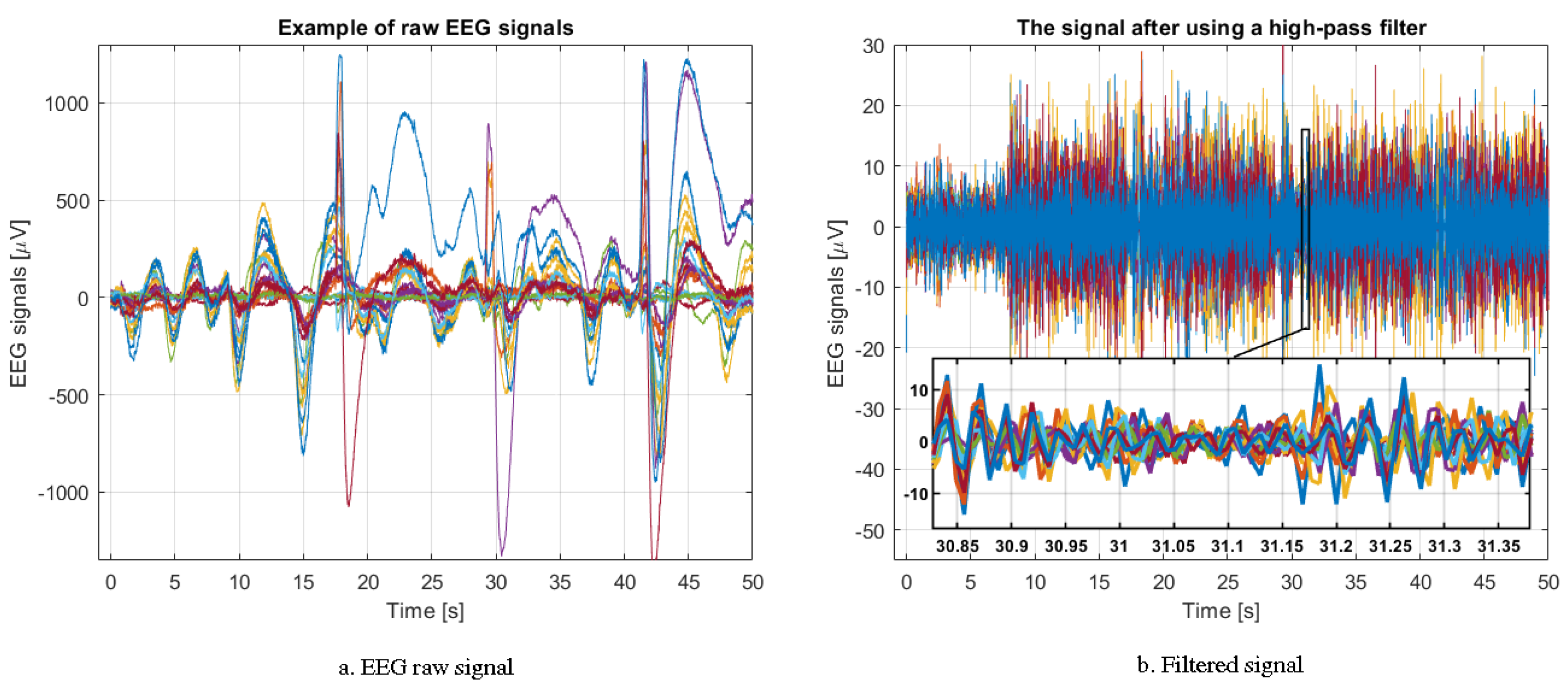
The designed system is composed of several components. The signal collected by the Emotiv EPOC Flex device goes to the computer connected with the set. The raw signal should be properly filtered (see
Section 3.1) as such data is difficult to qualitatively evaluate and classify.
The same applies to the EMG signal, which is filtered using a moving average of 5 voltage measurements. Such a procedure is necessary in order to smooth the signal and make it easier to read by the user, and with the intention of removing of various types of interference.
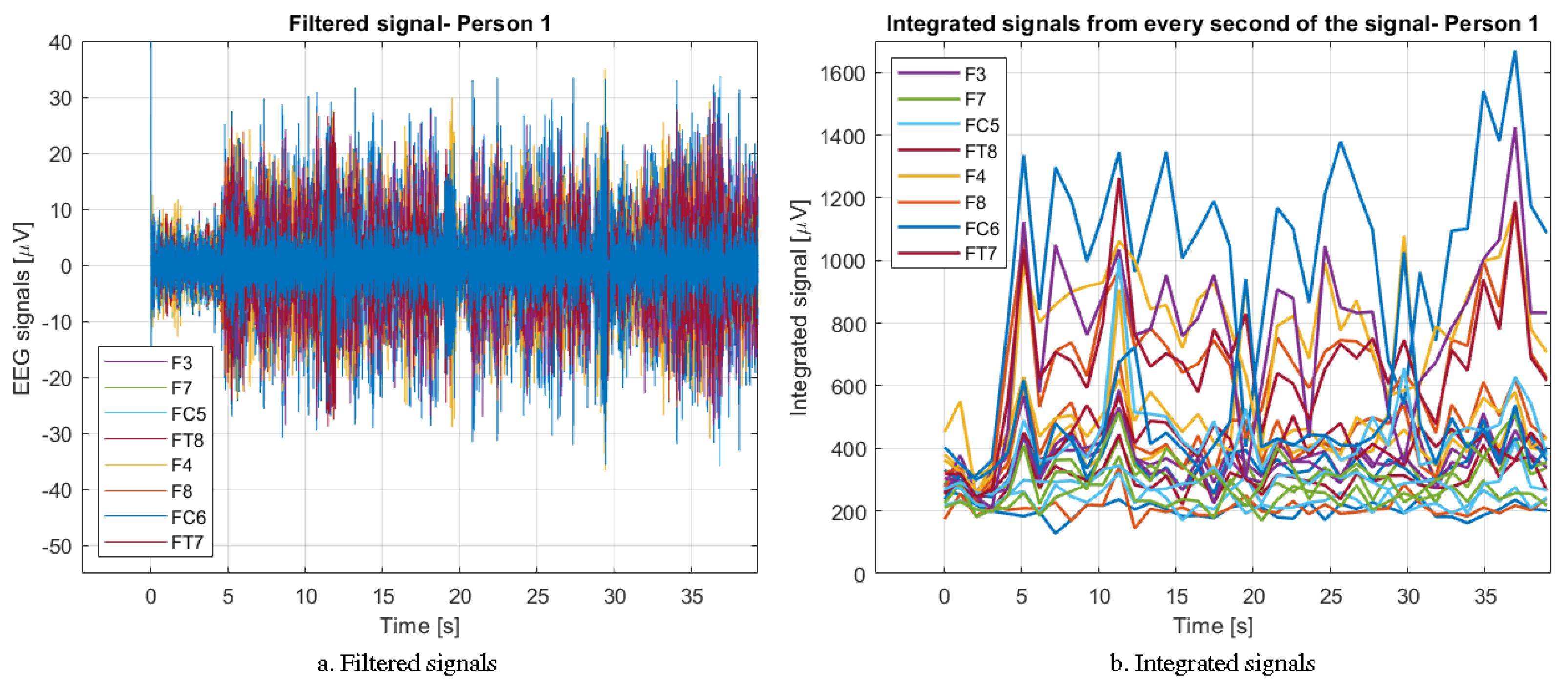
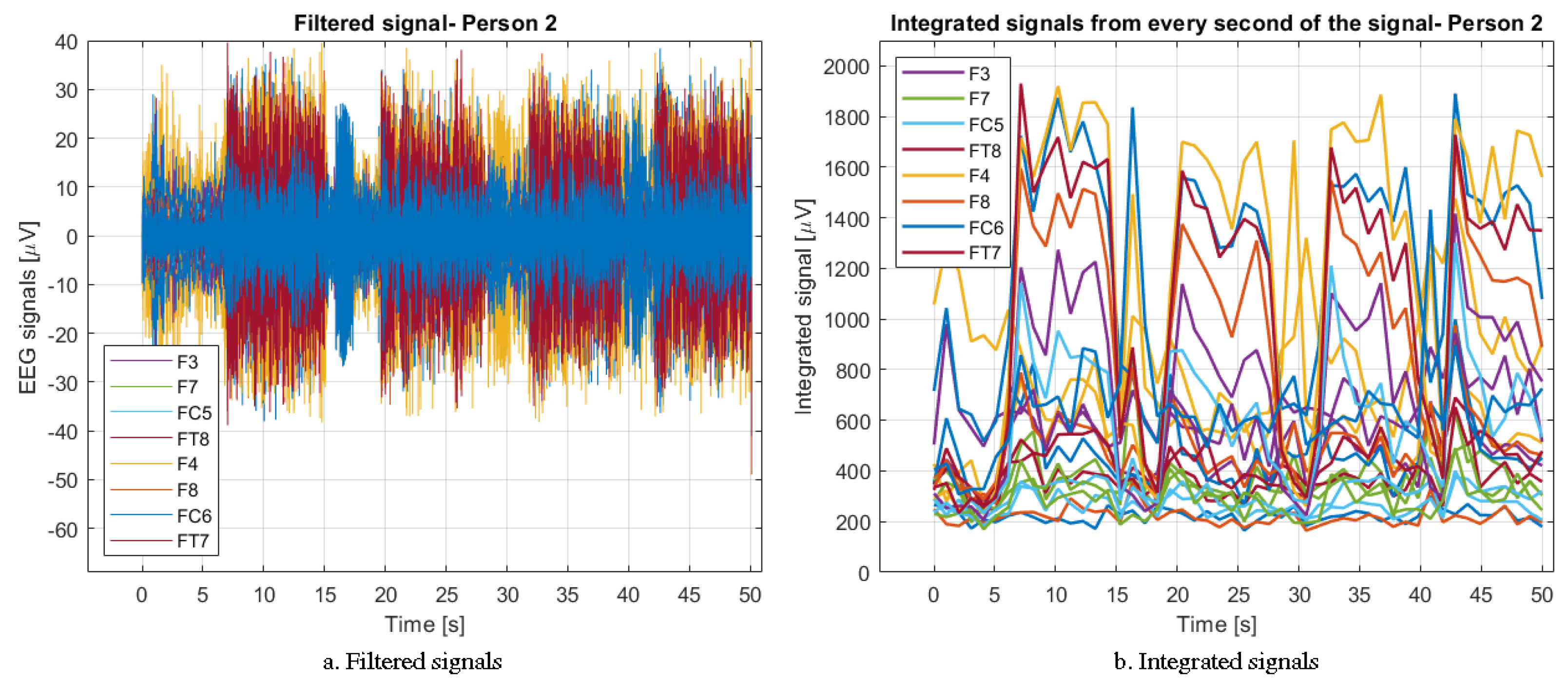
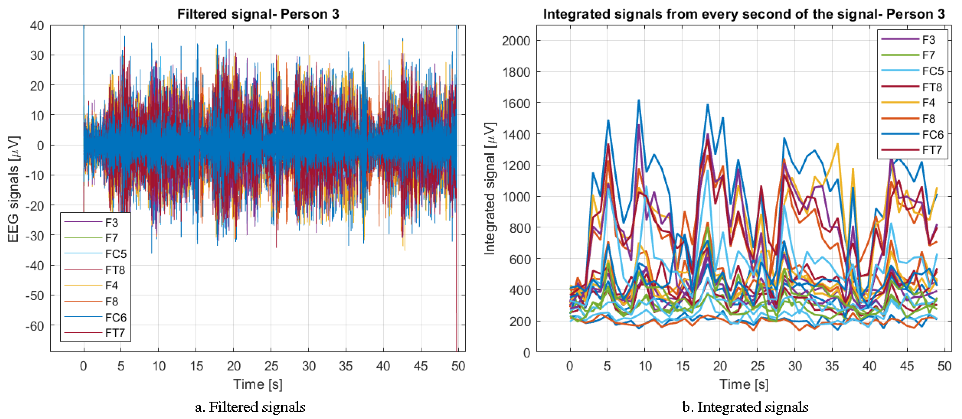
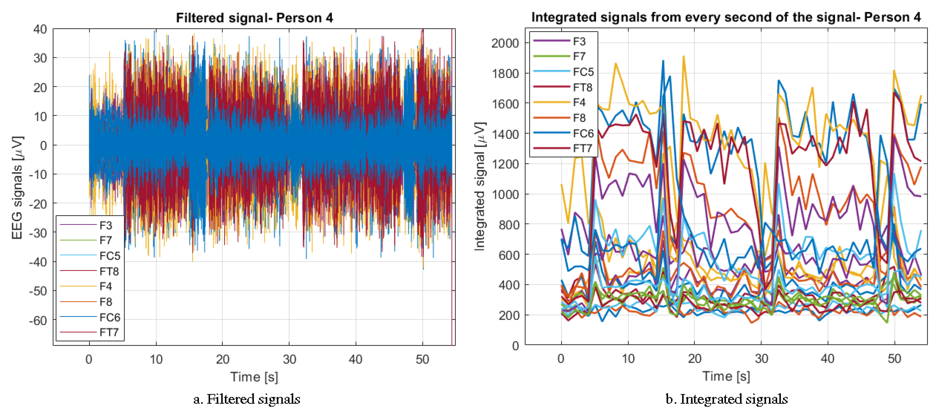
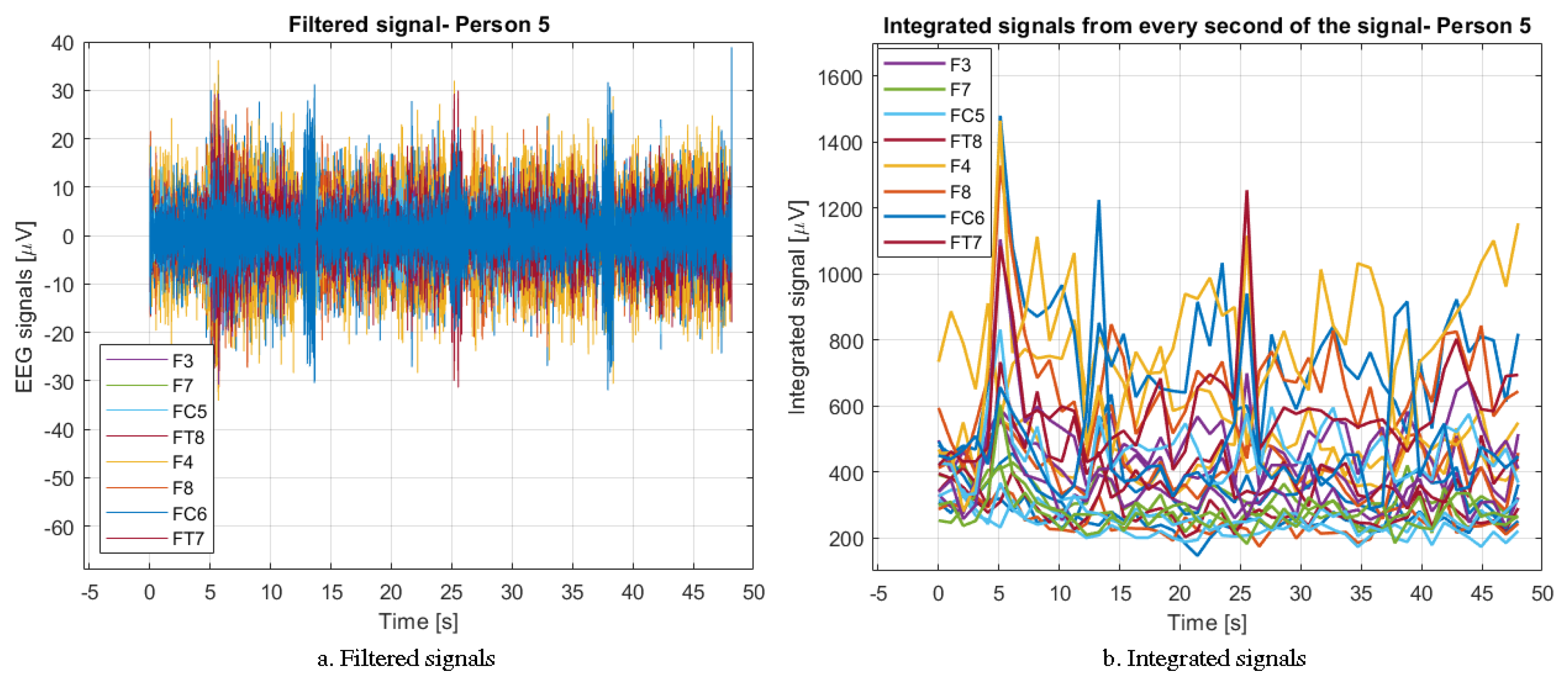
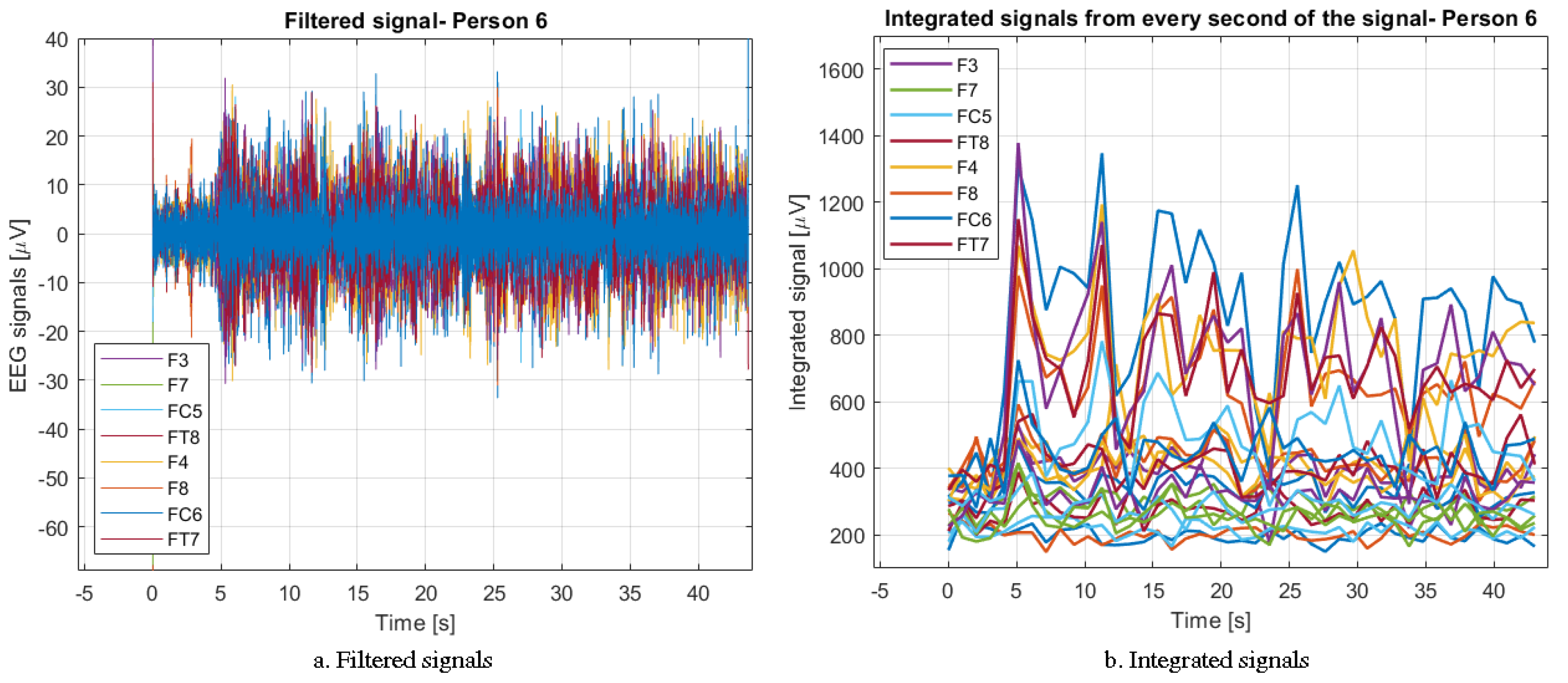
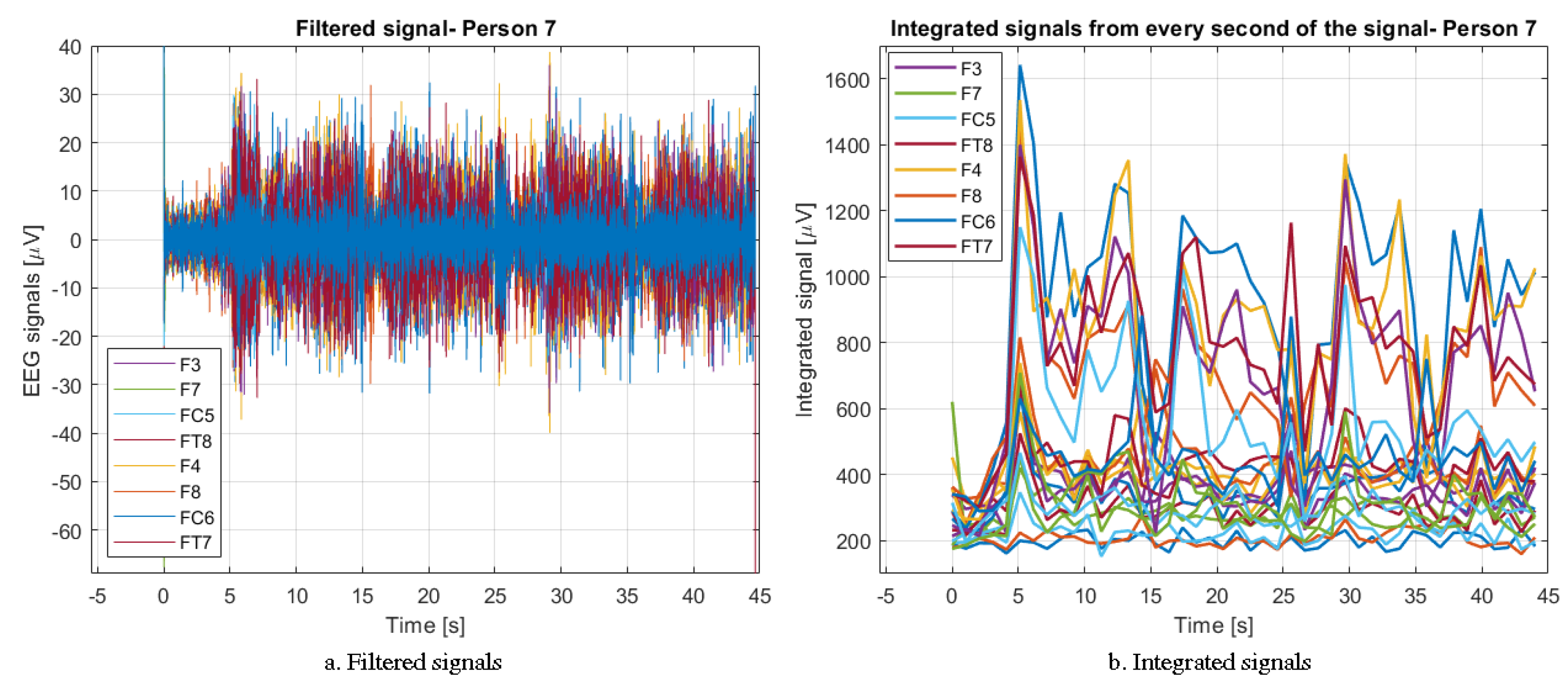
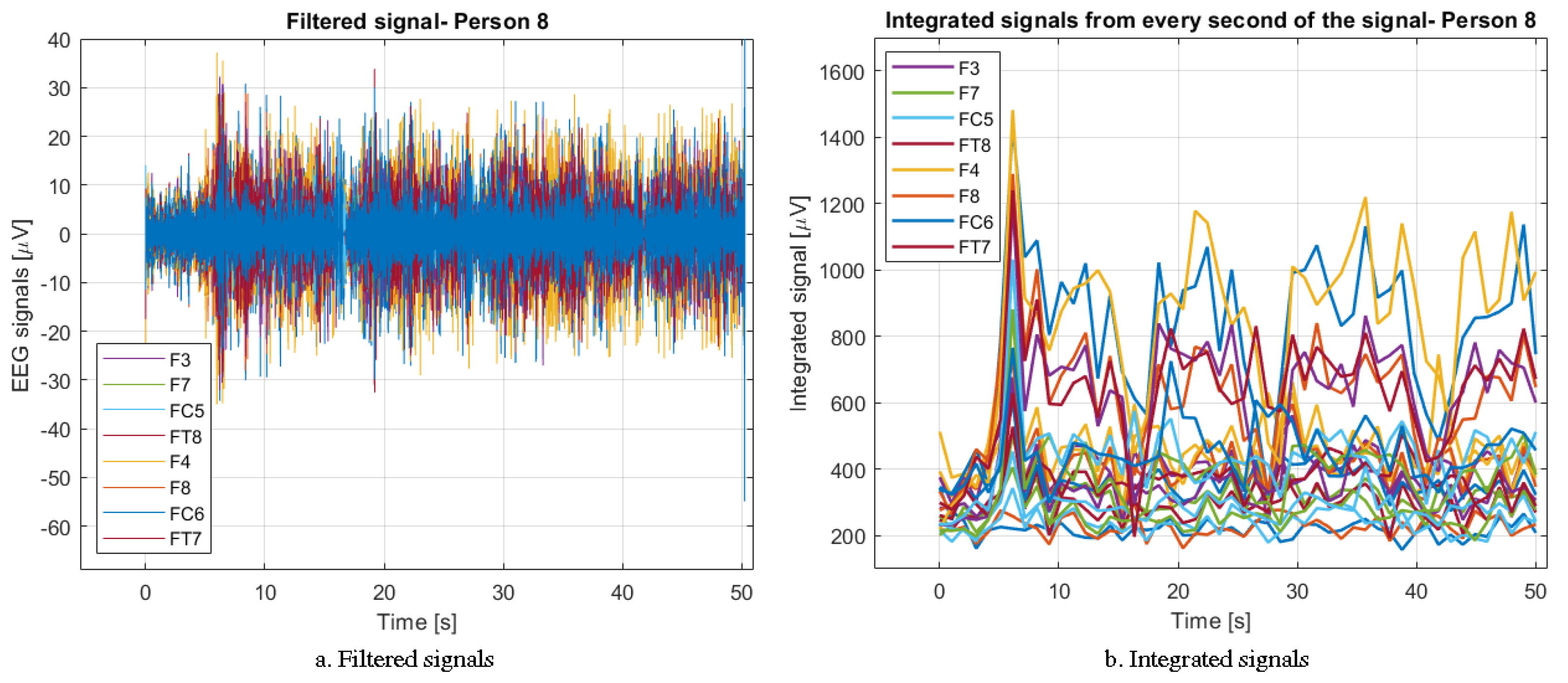
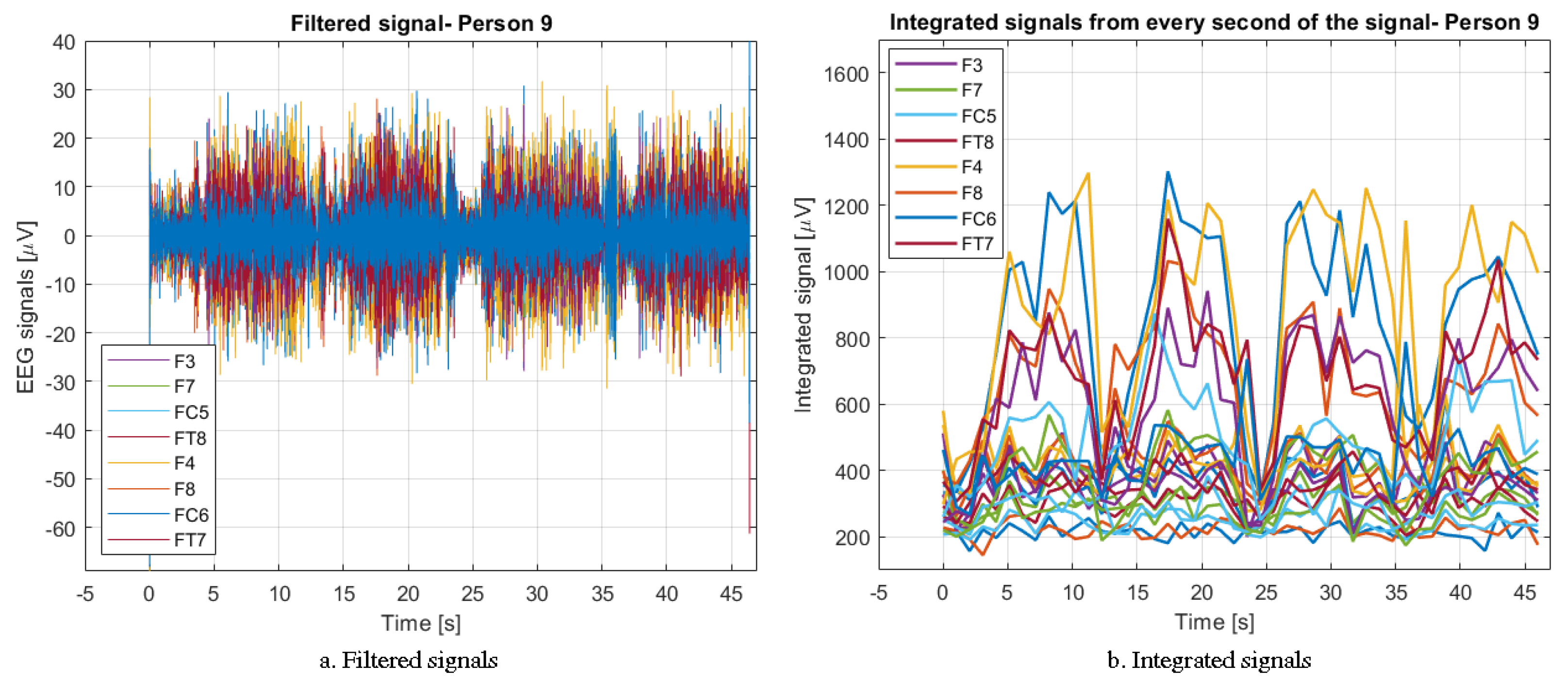
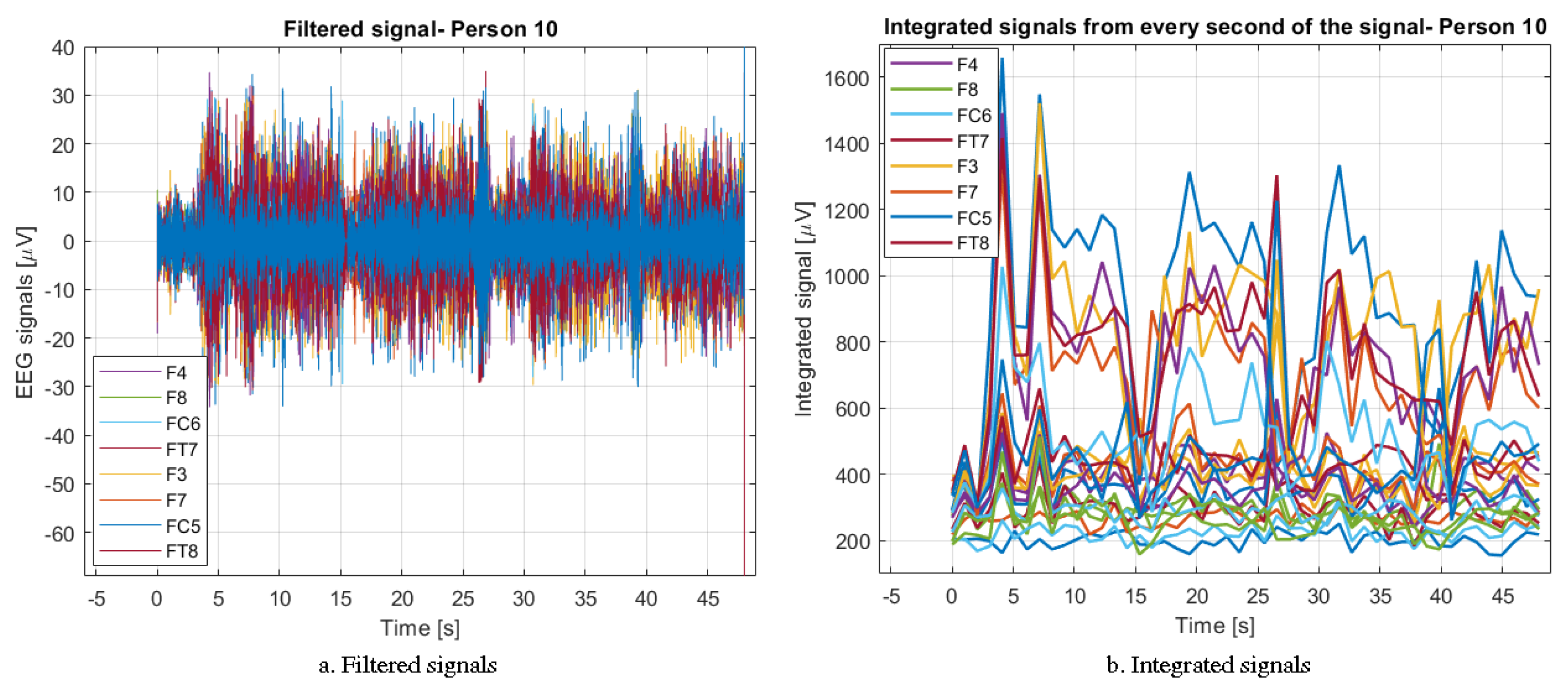
The EEG signal after the filtering operation is subjected to time-integration for each of the 22 electrodes separately. It is therefore a reuse of this method that took place in the [
5] pilot test preceding this study. The signal integration is performed for one second during the entire duration of the signal. The result is one-second integrated samples. This approach is simple but effective, because thanks to it the system is able to efficiently classify two states of interest to researchers, i.e., the image of movement and the lack of it. Details on the integration method and filtering of the EEG signal are provided in
Section 3.1.
The modified EEG and EMG signals (see
Figure 1) are assessed by an expert system. This program is used to classify them accordingly (see
Figure 1 and
Figure 5). Its structure is composed of several cooperating algorithms. The most crucial element of the classification system is the feed-forward neural network. The use of this method related to artificial intelligence is quite simple and effective at the same time, so it was decided to choose it again. In the current approach, the multilayer neural network has 22 inputs and 2 outputs, as it classifies only two signal states, i.e., arm movement selection and no arm movement. The second algorithm cooperating with the neural network is a classic algorithm that classifies three selected states, i.e., blinking the right and left eyes, as well as blinking both eyes at the same time. Both parts of the system have an appropriate set of data at the output, which then goes to the verification algorithm (see
Figure 5).
Moreover, the classified EMG signal is fed to the same algorithm. The program that analyzes this signal outputs a binary value, where the zero value means no muscle stimulation, and the binary one means shortening the muscles by the examined person. (see
Figure 5).
The recognized EEG and EMG signals checked by the verification algorithm trigger a forward and right or left command. It can be passed to the robot to execute requested commands (see
Figure 1). The robot is controlled only when the arm muscles are not moving. If the verification of the EMG signal indicates the activation of this part of the muscles, the command of movement to the motors of the LEGO Mindstorms EV3 mobile robot is interrupted.
6. Explanation of the Functioning of the Artificial Neural Network: Classification Part
In the present part of the article, a description and properties of the approach using the feed-forward neural network are presented. As part of the [
5] research, the results were obtained comparing the aforementioned network with the recursive Jordan network. In line with the results achieved, it was decided to continue to use the simple, reliable, yet effective feed-forward neural network.
The network was trained based on the
I(input) training dataset and
O(output). The first of them was the input training set, consisting of 22 network inputs representing the measurement channels of the EEG signal. They are marked as a matrix of patterns
i with the number of rows
a = 22. The input values were the integrated 1-second periods of the EEG signal, which are shown in
Figure 6,
Figure 7,
Figure 8,
Figure 9,
Figure 10,
Figure 11,
Figure 12,
Figure 13,
Figure 14 and
Figure 15.
The initial training data set was included as
o with the number of lines
b = 2. This state of affairs is naturally dictated by the requirements of the network used. It is the recognition of a 0–1 signal, i.e., imagining the movement of the arm or not. The issues discussed are presented in Formulas (
5) and (
6) [
5].
The discussed matrix of output patterns is presented in the following order:
The input and output training patterns included the same number of input and output elements by trial and error. It was found that the satisfactory results are obtained from the set consisting of n = 450.
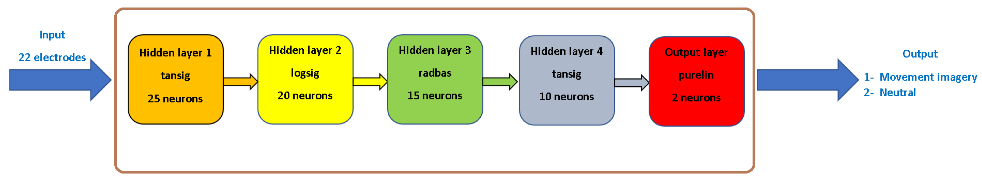
Figure 17 shows the neural network used to classify the periodically integrated EEG signal.
The Feed-Forward Network that was used in the conducted research consists of four hidden layers and one output layer. The first layer includes the tangesoid function
with the number of 25 neurons. The second function is
with 20 neurons. The third layer, consisting of 15 neurons, is the radial function (
). The penultimate, fourth activation function, consisting of 10 neurons, is
, while the output layer is represented by a linear activation function
composed of 2 neurons. It is closely related to the number of outputs of the neural network. It is responsible for summing up the nonlinear activation functions of neurons.
Figure 17 shows a simplified diagram of the designed feed-forward neural network.
Section 7 will present the results of the classification of the integrated EEG signal periods. The results of robot control based on various signals, i.e., waveforms with mental commands and positive verification by the collected EMG signal, will also be presented, as well as the influence of arm muscle stimulation on the signal controlling the mobile robot.
7. The Results of a Classification of a Motion Imaging from the EEG Signal with a Verifier in the Form of the EMG Signal
This section describes the effects of the designed classification system. The classification and verification of EEG and EMG signals were tested by an expert system consisting of classical algorithms, as well as those involving artificial intelligence.
Section 6 describes the neural network algorithm, while
Figure 18,
Figure 19,
Figure 20,
Figure 21,
Figure 22,
Figure 23,
Figure 24,
Figure 25,
Figure 26 and
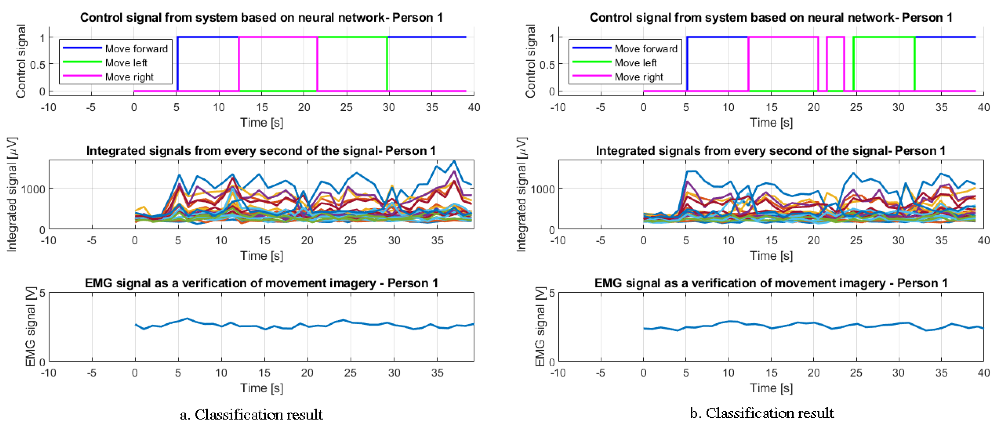
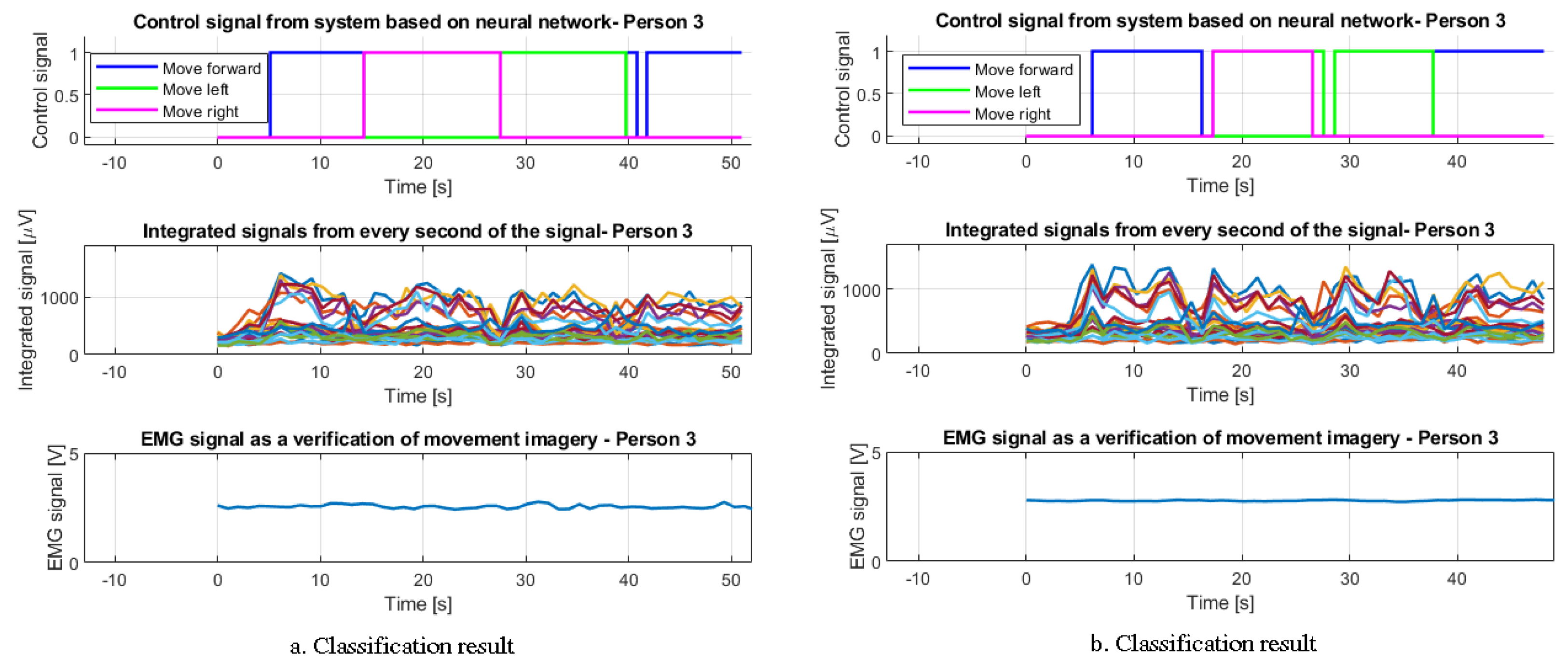
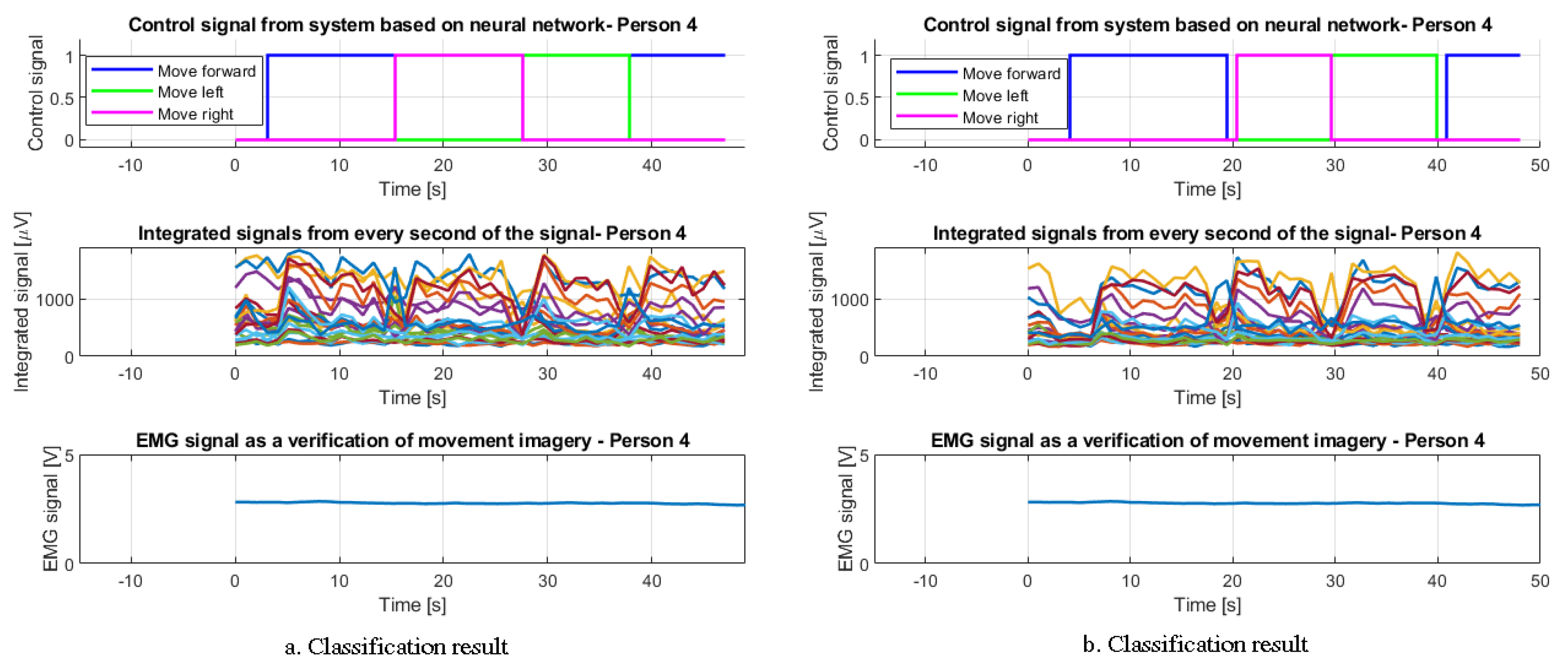
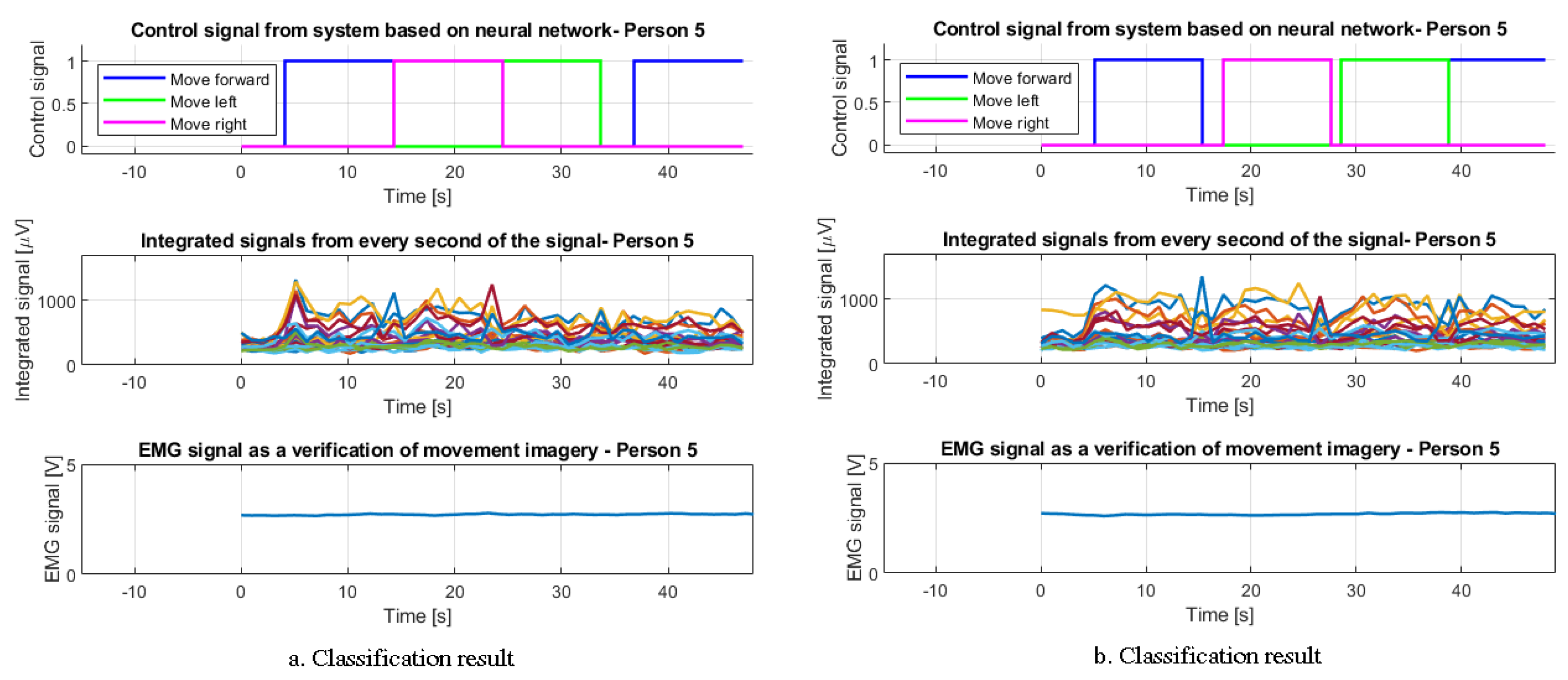
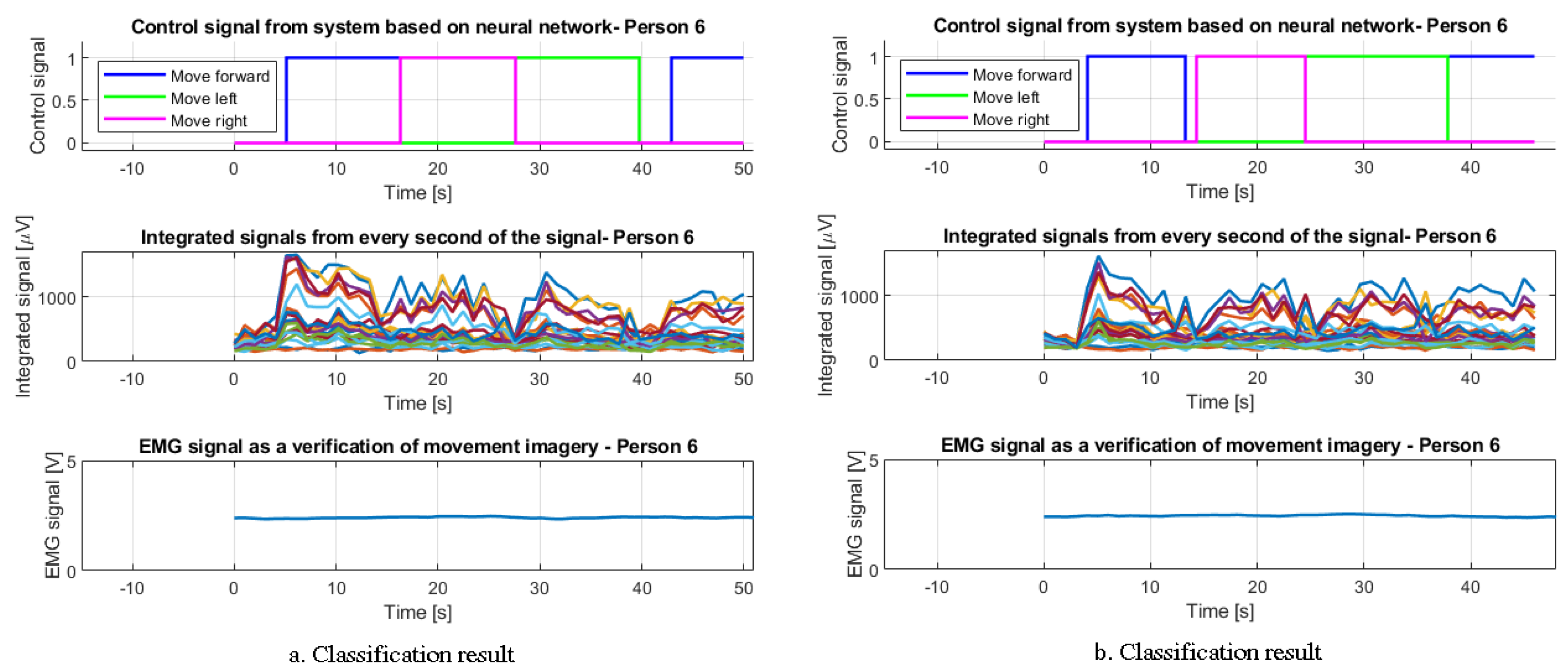
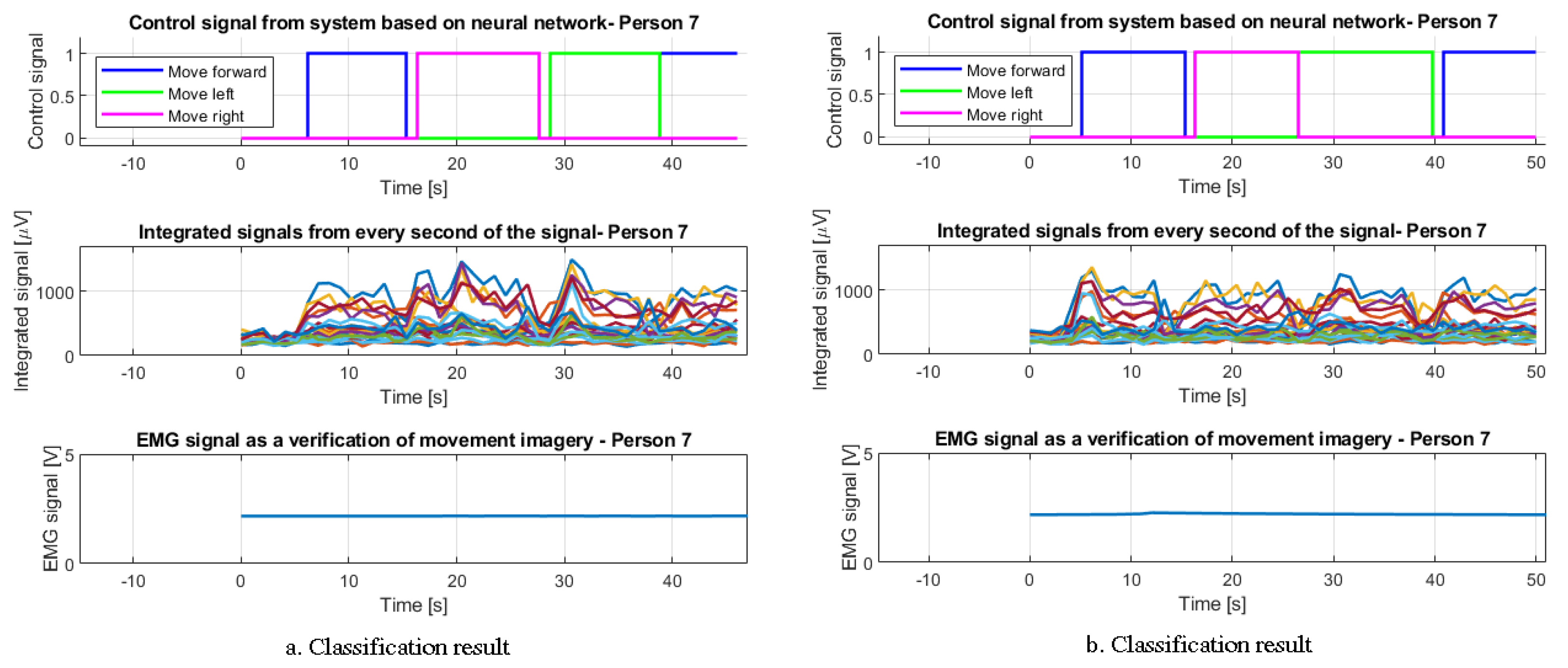
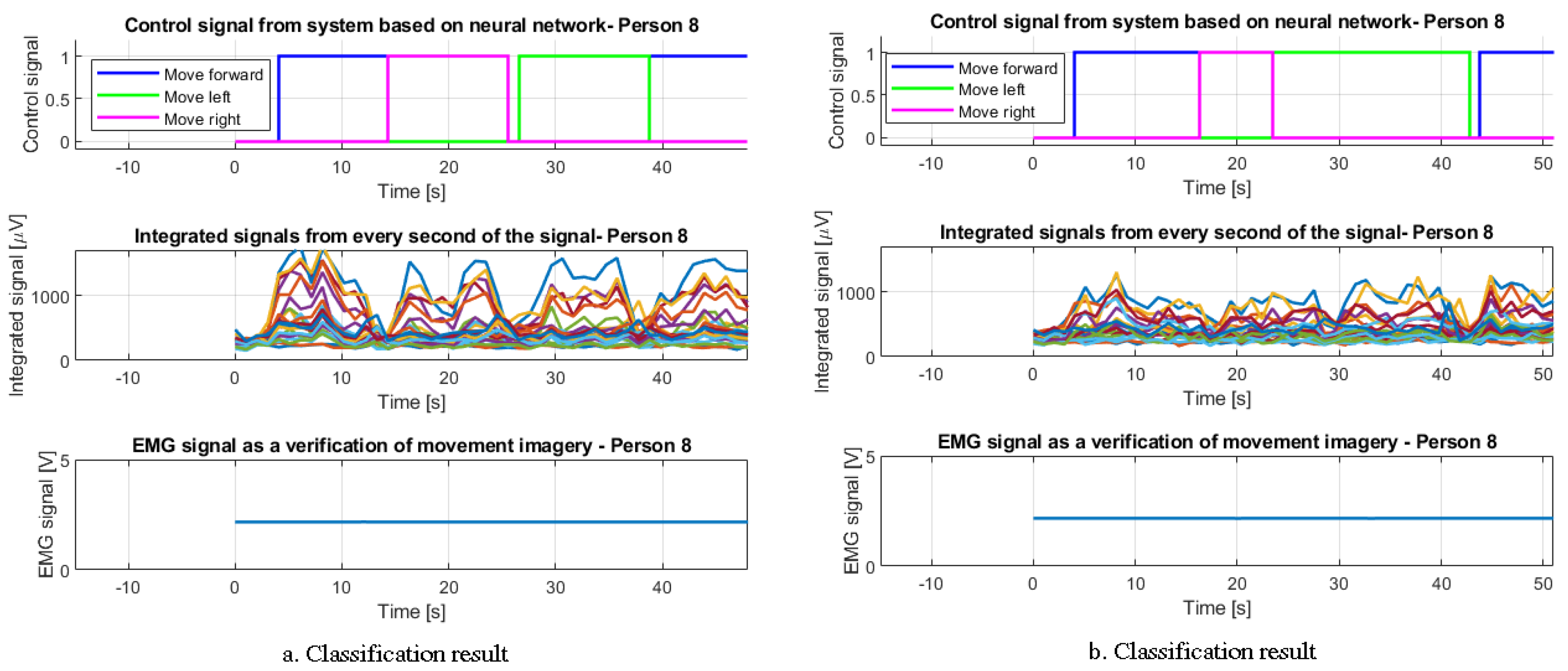
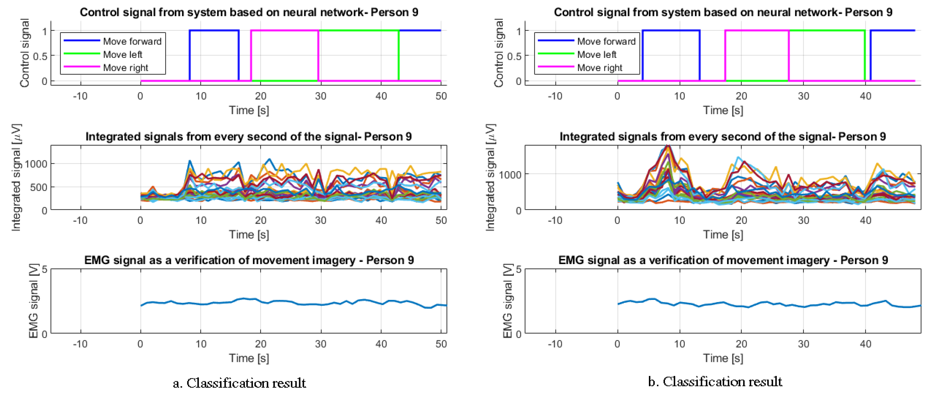
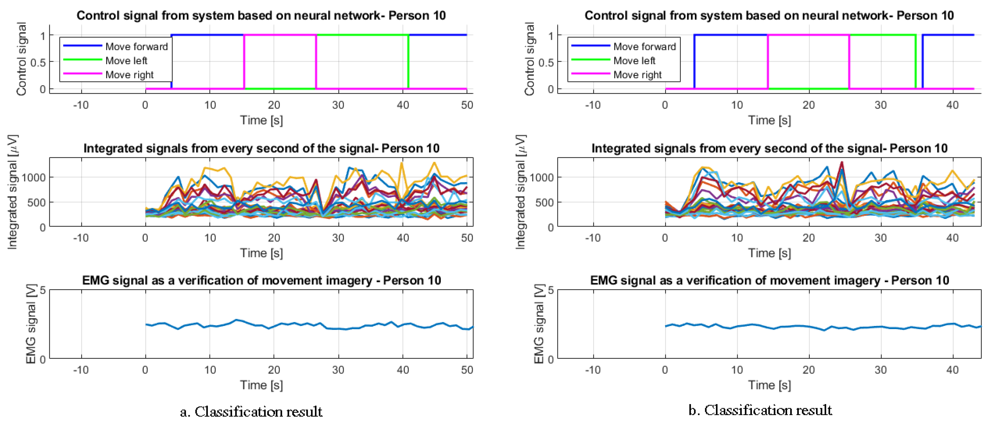
Figure 27 present exemplary classification results along with the resulting control signals. It was decided to present only two exemplary results for each of the 10 respondents due to the consistency of this article. Each drawing contains the integrated signal of each second of the EEG measurement run for all channels. In addition, we can observe the classification result in the form of a control signal for a mobile robot (move forward, move left, move right). The course of the EMG signal is closely connected with the classification result. Its purpose is to verify the lack of movement of the arm muscles. The following part of the article presents an example of robot control using a classified signal and the influence of muscle movement on robot control.
The forward, left, and right control signals are not fully continuous. The reason for this is the fact that in the moments when the EEG signal showed an artifact in the form of eyelid blinking, a significant disturbance of the correct classification of the signal occurred (about 2 s). An additional reason is also the lack of focus by the test participants, who, after blinking, took a few moments to return to focus and visualize the arm movements.
Figure 28 and
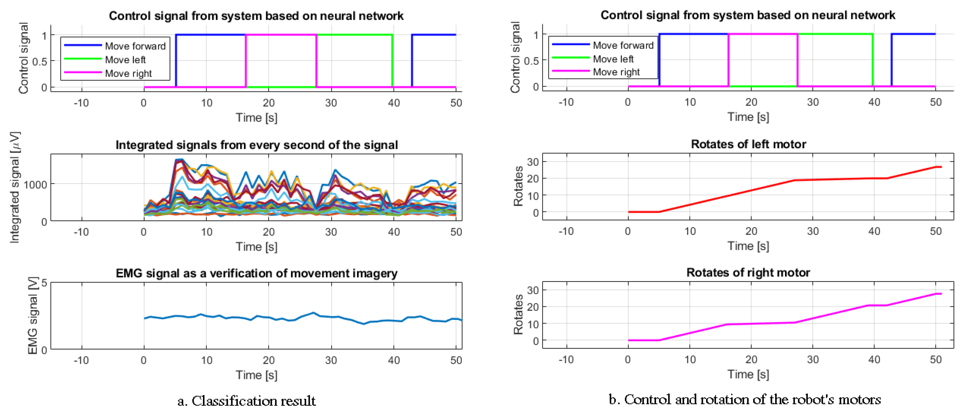
Figure 29 show an example of collecting signals from encoders of a mobile robot, which was controlled by signals classified by the system.
Figure 28 and
Figure 29 show that both wheels move forward during the control signal, and that only the right motor moves for the left movement, while the right movement is possible due to the rotation of the left motor.
One of the results (see
Figure 28) shows an example of the classification of EEG and EMG signals. The resulting control signal is fed to the mobile robot. The result is the measurement of the rotation of the drives of both wheels.
Moreover, an example of the influence of negative verification of signals by the system due to the detection of arm-muscle movement based on the evaluation of the EMG signal is also presented (see
Figure 29). This is reflected in the movements of the LEGO Mindstorms EV3 robot.
8. Discussion of Obtained Results
In order to discuss the obtained results, attention should be paid to the originality of the proposed system in terms of EEG signal classification, along with the verification of mental commands without muscle movements performed using the EMG signal.
The project describes the structure and components of an expert system composed of several key elements. Algorithms that include artificial intelligence and the classic approach to classification work together in it. The applied division of tasks is not pointless, as such a solution enables efficient classification and effectiveness of the proposed system. A system based solely on a neural network could have some drawbacks and face many difficulties in distinguishing the three key aspects. They are: forearm movement image recognition, artifact recognition and EMG signal verification in terms of finding arm muscle movements. The main goal of the system was its effectiveness and reliability when tested by different participants.
By observing the results shown in
Figure 18,
Figure 19,
Figure 20,
Figure 21,
Figure 22,
Figure 23,
Figure 24,
Figure 25,
Figure 26 and
Figure 27, we can see that the classification of signals is correct. The system recognizes the user’s mental commands very well. Correct recognition of artifacts in the signal is also worth noting. Their presence is used as a “switch” for further control commands of the mobile robot. Thus, blinking the right eye is characterized by the activity of the FC6 and F4 channels, while blinking the left eye causes an increase in the potential on the FC5 and F3 electrodes. Of course, the movement of both eyelids will make all four channels active. This solution is very effective and unambiguous for the classification system. However, its drawback should be noted. It cannot be used for completely paralyzed people, in whom it is impossible to move the eyelids of the eyes.
First of all, we need to consider the results presented in
Figure 18,
Figure 19,
Figure 20,
Figure 21,
Figure 22,
Figure 23,
Figure 24,
Figure 25,
Figure 26 and
Figure 27. They are the most crucial as they show the nature of the functioning of the classification system. The 10 participants who took part in the tests were people of different ages, of different sex, and differed in other factors, which could, to a greater or lesser extent, influence the results.
The results obtained in the
Table 1 allow us to work out many conclusions. Their essence is crucial in assessing the entire designed system.
First, it should be noted how diverse the mean value of the integrated EEG signal is for 10 people. It is important to note that the raw characterization would be even more difficult to classify. Each of the study participants made it possible to obtain completely different results obtained in the measurements. The authors emphasize that this is the average measurement of the integrated signal from all 15 trials for each participant and should not be directly related to the results obtained in
Figure 6,
Figure 7,
Figure 8,
Figure 9,
Figure 10,
Figure 11,
Figure 12,
Figure 13,
Figure 14 and
Figure 15. From
Table 1, it can be clearly seen that the course of the measured value for each person was completely different and its average range oscillated up to: 886 μV for the electrodes
/
, 785 μV for
/
electrodes, 795 μV for
/
electrodes, and 856 μV for
/
electrodes. As part of the research, it was decided to use pairwise recording of channels (e.g.,
/
), because depending on the participant, his brain activity during visualization of movement was variable depending on the activity of a given part of the cerebral cortex.
The second point that should be noted is the wide scope of operation and classification of the integrated signals by the designed expert system. The used neural network should correctly classify the motion selection using different signals with varying amplitudes. Care was taken to ensure that its functioning allowed for the correct interpretation of the EEG waveforms. This state of affairs shows that the algorithm is resistant to signal variability, which depends on the measurements obtained on the participants of the study.
The EMG signal measured in all tested people has very similar values, oscillating around 2V, and the movement of muscles has a very characteristic effect on the measurement result; hence, the system detects this phenomenon very quickly.
It is worth comparing the designed algorithm with other systems that can be found in the literature review. In [
45], two data sets were assessed, i.e., the Open BCI data set and EEG signals obtained by Emotiv EPOC. The proposed system shows an overall accuracy of
and
for both datasets, respectively. In [
46], the authors propose densely feature fusion convolutional neural networks (DFFN). The simulation results resulted in a
rating improvement in the BCI IV-2a dataset compared to regular CNN. Citing the above-mentioned studies only shows that the interest in classification and generally understood improvement of bioelectric signal processing is still popular and developed.
The unquestionable advantage of the artificial neural network is its resistance to artifact interference, as the
F3 and
F4 channels are also one of the most important when detecting the mental arm movement command. Training of the feed-forward neural network was performed using 450 input and output training patterns, where the inputs were integrated EEG signals, and the outputs were a signal representing an image of movement, or lack thereof. Such a simple solution allowed us to make the system more reliable. The applied solutions turned out to be effective, as shown in
Figure 6,
Figure 7,
Figure 8,
Figure 9,
Figure 10,
Figure 11,
Figure 12,
Figure 13,
Figure 14 and
Figure 15 and
Section 4, presenting the results of signal pre-classification, as well as the characteristics
Figure 18,
Figure 19,
Figure 20,
Figure 21,
Figure 22,
Figure 23,
Figure 24,
Figure 25,
Figure 26 and
Figure 27 in
Section 7, which contain sample results of signal classification.
Importantly, negative EMG verification successfully interrupted the LEGO robot’s movement commands when muscle movements were detected (see
Figure 29). In its absence, the device was controlled directly on the basis of the EEG waveforms classification. The discussed facts confirm the results obtained from the robot’s encoders, which show the variable movement of its drives over time.
9. Conclusions and Future Work
The system presented in this article offers many opportunities for development and is adapted to further research in terms of its use by people with disabilities. The verification of the EMG signal made it possible to check how the algorithm would work in the case of mental commands without additional muscle stimulation, as would be the case with paralyzed people. This is very important as such participants cannot move their limbs.
It should also be noted that the level research work with the use of the Emotiv EPOC Flex Gel (EEG) headset in this type of project is very small. It is a simple device that provides satisfactory accuracy. In addition to this, regarding the use of MyoWare Muscle Sensor (EMG), it turns out that their combination is an original solution, which further confirms the uniqueness of the project. Further research may provide a better understanding of other uses for one or both of the devices. Therefore, it is possible to emphasize the originality of the research carried out in the context of the lack of cooperation between the Emotiv and MyoWare devices. The literature review confirms this state of affairs.
Summarizing the results obtained in the experiment, it is possible to conclude that the tasks set for the system classifying integrated EEG signals and verifying muscle movements have been fulfilled. An undoubted advantage is the possibility of further research leading to the development of the system, especially in terms of deep learning. It would be good to test the system on people with disabilities. This would probably make it possible to better adapt it to their needs in such a way that in the future it could serve them and improve their functioning. The further development of artificial intelligence will certainly make it possible to classify biomedical signals even more effectively. The authors hope that the proposed approaches to the problem of classification and verification of mental commands will be developed, improved, and resistant to various disturbances occurring in the signal waveforms.


