Article

Numerical Investigation of the Temporal Contrast in ps-OPCPA with Compact Double BBO Arrangement

1
State Key Laboratory of High Field Laser Physics and CAS Center for Excellence in Ultra-Intense Laser Science, Shanghai Institute of Optics and Fine Mechanics (SIOM), Chinese Academy of Sciences (CAS), Shanghai 201800, China
2
Center of Materials Science and Optoelectronics Engineering, University of Chinese Academy of Sciences, Beijing 100049, China
*
Authors to whom correspondence should be addressed.
Submission received: 16 December 2021 / Revised: 12 January 2022 / Accepted: 14 January 2022 / Published: 17 January 2022
(This article belongs to the Section Optics and Lasers)

Abstract

:
The picosecond optical parametric chirped pulse amplifier (ps-OPCPA) with double BBO arrangement can support the ultrabroad spectrum even under a relatively long pump pulse duration (∼100 ps). In this work, five-wave-coupled equations taking into consideration different phase matching conditions between the parametric superfluorescence (PSF) and the signal are proposed to investigate the temporal contrast in ps-OPCPA schemes. Both the temporal contrast and the amplified spectrum are numerically analyzed in double BBO arrangements with four phase matching conditions. Numerical results show that the high temporal contrast and ultrabroad spectrum can be simultaneously realized by choosing the proper phase matching geometry in a double BBO arrangement. The numerical investigation here relaxes the requirement of very short pump pulses in ps-OPCPA, which can provide beneficial guidance for the design and construction of ps-OPCPA.

1. Introduction

Optical parametric chirped pulse amplifiers pumped by picosecond pulses (ps-OPCPA) have provided effective approaches for generating intense few-cycle laser pulses, which can be widely applied to investigations of high-order harmonic generation (HHG) [1,2,3] and particle acceleration [4,5,6].
There are two main types of ps-OPCPA schemes in terms of the duration of pump lasers. On the one hand, OPCPAs pumped by very short pulses (<10 ps) are favorable for three advantages [7]: (i) a small stretching and compression factor for seed pulses is needed so that simple systems, such as bulk material and chirp mirrors, can be used for stretching and compression; (ii) the amplification bandwidth can be very broad because of its high pump intensity; (iii) the time window of temporal contrast is well controlled due to the instantaneous interaction of the short-pulse OPCPA systems. A representative system pumped by 0.8 ps Yb:YAG lasers [8] supported a Fourier-limited pulse duration below 6 fs, but 42 mJ, 7 fs pulses were finally obtained due to the high order dispersion. Besides, a number of stringent requirements also need to be satisfied in the short-ps-pumped systems. First of all, starting from the pump compressor, all parts of the systems have to be located in a vacuum to reduce nonlinear distortions [8], which greatly increases the cost. Although the slight increase of pump duration to 5ps mitigated this disadvantage [9], short-pulse OPCPA is still difficult to design and construct because the CPA geometry is necessary for pump lasers to achieve high energy [10,11]. What is more, it poses challenges to the synchronization technique in the parametric amplifying process because the timing jitter between the pump and seed becomes more sensitive in short-ps-pumped systems.
On the other hand, multi-TW-level few-cycle systems pumped by long pulses (60–120 ps) have also been demonstrated [12,13,14,15]. In these systems, grisms [16,17] are usually used to stretch few-cycle lasers to several tens of picoseconds, and bulk material and chirp mirrors are used for compression [18]. In addition, acousto-optic programmable dispersive filter (AOPDF) [19] are used to control the high order dispersion, so that almost Fourier-limited pulses could be obtained. However, grisms and AOPDF have a low transmission of around 10% which leads to the lower energy of input pulses. Therefore, seed pulses with large energy and high contrast are generally required to overcome the energy loss mentioned above. Regarding the amplification bandwidth, it can be improved by using some techniques. For instance, as reported in [13], the seed pulses were stretched only 1/5th of the pump pulse duration, which suppressed the spectrum narrowing and produced 15.5 mJ, 7.6 fs (<3 cycles) pulses. However, the small signal-pump ratio leads to a low conversion efficiency. A two-color scheme with 355 nm and 532 nm pumps supported the spectrum ranging from VIS to NIR range, and 75 mJ, 4.5 fs (<2 cycles) pulses were obtained [14]. However, this approach might limit the repetition rate of the system because of the UV pumping process. The SYLOS2 in the extreme light infrastructure attosecond light pulse source (ELI-ALPS) adopted a compact double BBO arrangement, and 32 mJ, 6.6 fs (<2.3 cycles) pulses were generated [15]. In this arrangement, two cascaded BBO crystals with different phase matching angle amplifies different parts of spectrum and thus supporting broader spectrum. The similar arrangement was reported in [20,21]. It is very attractive, but parametric superfluorescence (PSF) in this spectral multiplexing method is likely to be amplified to a much higher level due to the longer interaction length, which has not been studied in detail. For this reason, we theoretically investigate the temporal contrast degraded by the incoherent PSF in double BBO arrangement. The remainder of this paper is organized as follows.
Firstly, the numerical model is presented to investigate the broadband amplification of signal pulses and PSF in Section 2. Secondly, based on this model, a 100-ps-pumped OPCPA with traditional configuration is simulated in Section 3.1. PSF with different phase-matching conditions is also compared conveniently. Thirdly, in Section 3.2 the temporal contrast in the compact double BBO arrangement is mainly calculated to look into the possibility of expanding the output bandwidth while keeping the high temporal contrast. Besides, the optimal arrangement of two crystals is discussed.

2. Numerical Method

PSF originates from a quantum fluctuation effect first predicted by Louisell with the quantum mechanical model [22]. It can be understood as the spontaneous splitting of pump photons to signal and idler photons and then being amplified along the nonlinear crystal together with seed pulses. As one main type of noise in OPCPA, PSF delivered to the target before the arrival of the main pulse may radically change the conditions of the interactions, so it has gained much attention in past decades [23,24,25,26,27,28].
In some work [28,29], PSF is assumed to propagate along the direction of the smallest phase mismatch because in this case it is amplified most efficiently and becomes considerable noise in OPCPA. Compared to the common non-collinear OPCPA, which eliminates the group velocity dispersion only at the specific wavelength—as depicted in Figure 1a—PSF under the perfect phase-matching assumption ( k = 0 ) has the feature of angular dispersion—as depicted in Figure 1b. Specifically, the frequency-dependent angle α f between signal fluorescence and pump pulses, and the angle Ω f between signal fluorescence and idler fluorescence can be determined by solving the momentum conservation relationships in non-collinear OPCPA geometry [30]:
α f ( ω s , ω i ) = arccos k p 2 + k s 2 k i 2 2 k p k s ,
Ω f ( ω s , ω i ) = π arccos k i 2 + k s 2 k p 2 2 k i k s ,
where k p , k i , k s are the wave numbers of the pump, signal and idler, respectively.
In addition, as shown in Figure 1b, α f is the angle between signal fluorescence and signal pulses and Ω f is the angle between idler fluorescence and signal pulses, which can be denoted by:
α f ( ω s , ω i ) = α α f ( ω s , ω i ) ,
Ω f ( ω s , ω i ) = Ω f ( ω s , ω i ) + α f ( ω s , ω i ) .
It is worth mentioning that actually PSF may have more complicated spatial structures as a result of its spontaneous generation. The assumptions that PSF has other phase-matching conditions could be investigated by choosing the proper α f and Ω f . For example, when α f equals to zero and Ω f equals to Ω , it corresponds to the case that PSF has the same phase mismatch with the signal. This condition and the perfect phase-matching condition of PSF will both be considered in Section 3.1. This angle information is necessary for simulating broadband parametric amplification in the frequency domain where the full dispersion is taken into account [31]. Besides, based on the model in [31], we develop the five-wave-coupled equations to include the amplification of PSF:
E ˜ p z + i k p cos ( α ) E ˜ p = i χ ( 2 ) ω p n p c cos ( α ) 1 cos 2 ( ρ α ) F E i ( t ) E s ( t ) , E ˜ s z + i k s E ˜ s = i χ ( 2 ) ω s n s c F { E p ( t ) E i * ( t ) } , E ˜ i z + i k i cos [ Ω ( ω s , ω i ) ] E ˜ i = i χ ( 2 ) ω i n i c cos [ Ω ( ω s , ω i ) ] F { E p ( t ) E s * ( t ) } , E ˜ s f z + i k s cos [ α f ( ω s , ω i ) ] E ˜ s f = i χ ( 2 ) ω s n s c cos [ α f ( ω s , ω i ) ] F { E p ( t ) E i f * ( t ) } , E ˜ i f z + i k i cos [ Ω f ( ω s , ω i ) ] E ˜ i f = i χ ( 2 ) ω i n i c cos [ Ω f ( ω s , ω i ) ] F { E p ( t ) E s f * ( t ) } ,
where F { …} denotes the Fourier transform; ρ accounts for the pump walk-off; l = p , s , i , s f , i f stands for the signal, idler, pump, signal fluorescence and idler fluorescence. E l ( z , t ) are their electric fields in the temporal domain; E ˜ l ( z , ω ) are the Fourier transform of E l ( z , t ) . E ˜ s f ( z = 0 , ω ) and E ˜ i f ( z = 0 , ω ) represent the independent fluctuations of the field [24]. The real and imaginary components of E ˜ s f ( z = 0 , ω ) and E ˜ i f ( z = 0 , ω ) are taken as uncorrelated Gaussian distributions with a zero mean value [24,32] and their variance is determined by the effective number of seed photons [33]:
N e f f = n 3 2 π ω τ .
This estimation is quite reliable because of the consistency with the latest experimental research [34]. Thus, the initial energy of PSF is estimated to be about 2 × 10 14 J for the temporal width of 100 ps and the spectrum ranging from 700 nm to 1250 nm. It is very small compared to the seed pulse, so it is assumed that PSF does not contribute to the depletion of the pump. However, the depletion of the pump due to the increase of signal energy will influence the gain of PSF. The above five-wave-coupled equations can be solved by the frequently used split-step Fourier-transform algorithm.

3. Results and Discussion

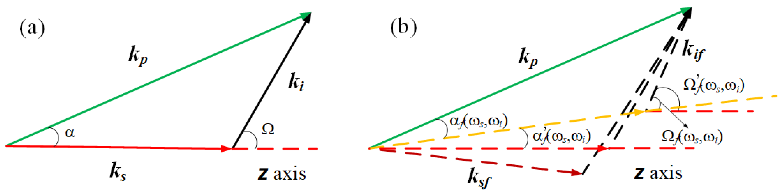
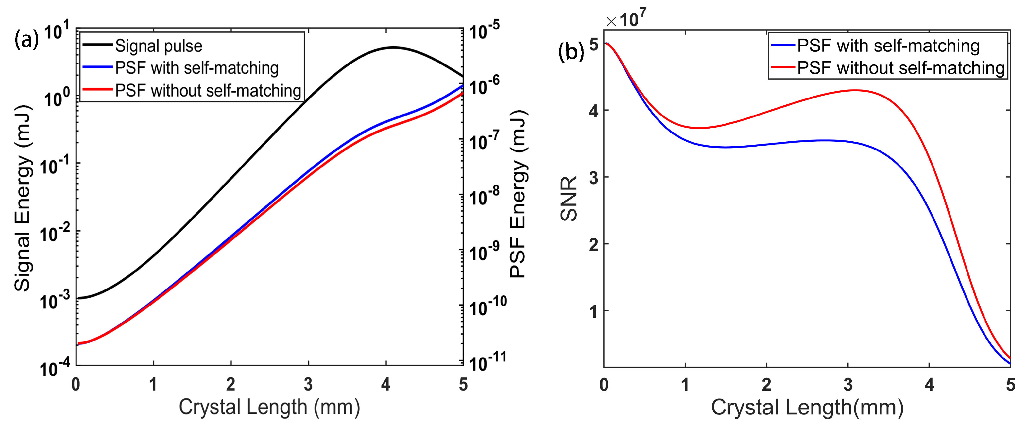
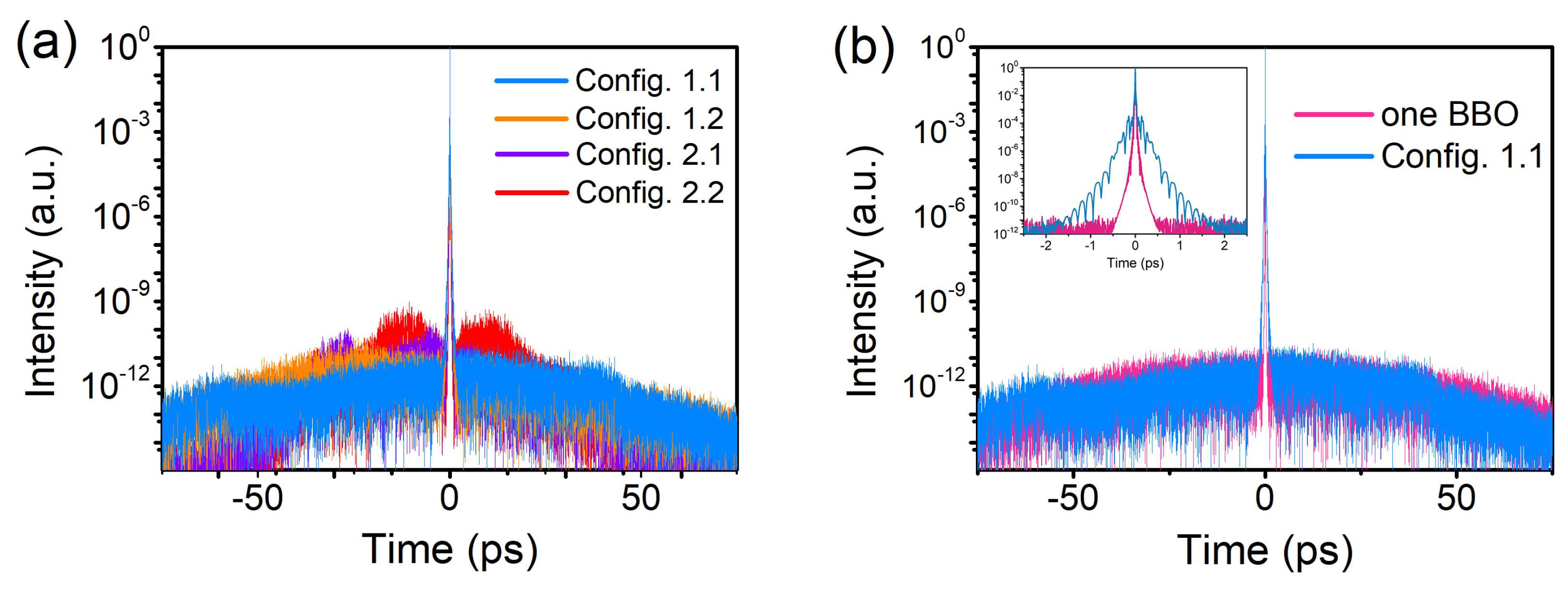
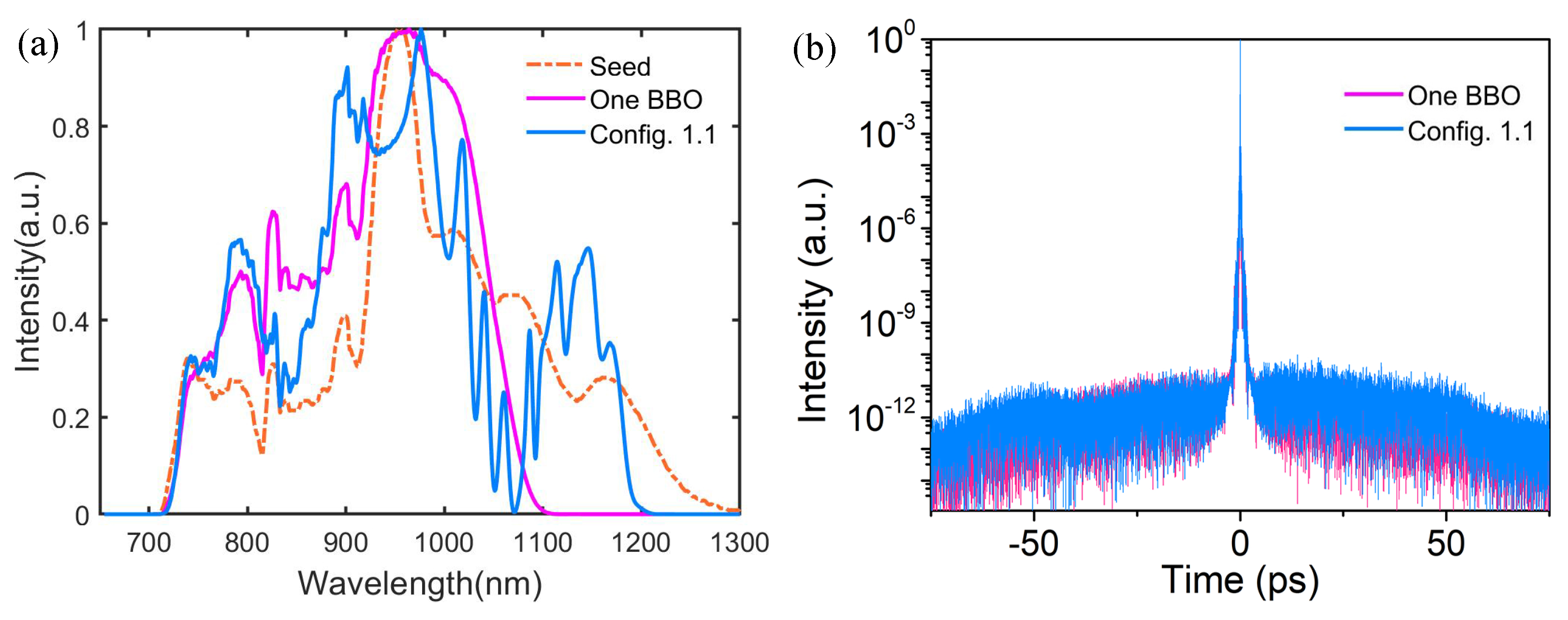
3.1. Temporal Contrast in the Traditional OPCPA Arrangement

The parametric amplification of signal pulses and PSF in a BBO crystal (type I, α = 2.274°, phase matching angle θ = 23.664°, pump wavelength λ p = 532 nm) is simulated here. The case in which PSF has a perfect phase-matching condition and the case in which PSF has the same phase mismatch with the signal are also compared. In our simulation, the pump pulse has a Gaussian temporal profile with a duration of 100 ps and pulse energy of 20 mJ, focused to a pump intensity of about 10 GW/cm 2 . The seed pulse has a super-Gaussian spectral profile with the energy of 1 μ J and it is stretched to 60 ps with the second-order negative chirp.
Figure 2a describes the signal energy and PSF energy versus the crystal length. Figure 2b describes the signal to noise energy ratio (SNR) versus the crystal length and the initial SNR is 5 × 10 7 (50 times on average). For both cases, the signal to noise ratio (SNR) decreases in the beginning of the amplification process because the idler grows from a zero electric field, which slows the efficient amplification of the signal. After propagating a short distance, the idler energy approaches the signal energy, and a slow increase of SNR is seen due to the much higher signal energy than the PSF energy. At the crystal length of 3.5 mm corresponding to the signal energy of 3.3 mJ, the saturation effect shows up and the SNR starts decreasing dramatically. When operated at this position, SNR is reduced to 3.3 × 10 7 and 4.1 × 10 7 for the cases in which PSF has the perfect phase-matching condition and the same phase-matching condition with the signal, respectively. The highest achievable signal energy is 5 mJ at the crystal length of 4 mm. At the crystal length of 5 mm, OPCPA moves into the oversaturated region, and the signal energy converts back to 2 mJ. The corresponding SNR is 2.1 × 10 6 and 2.9 × 10 6 for the two phase-matching conditions of PSF. The result shows that, although phase-matching properties have impacts on the parametric amplification, the difference of the PSF energy between two phase-matching cases is not significant in our simulation. The difference could be bigger for a longer crystal length. In the following simulation, only PSF with perfect phase matching is considered. The temporal profile of the signal and PSF is depicted in Figure 3a and the background level is observed to be 3 × 10 11 , 4 × 10 11 and 5 × 10 10 relative to the main pulse at the crystal length of 3.5 mm, 4 mm and 5 mm, respectively. As expected, the temporal contrast becomes worse as the crystal length increases. To ensure a better temporal contrast, the crystal length of 3.5 mm is recommended and the corresponding output spectrum expanding from 700 nm to 1100 nm is illustrated in Figure 3b for the comparison with the spectrum in a double BBO arrangement as will be discussed in Section 3.2.

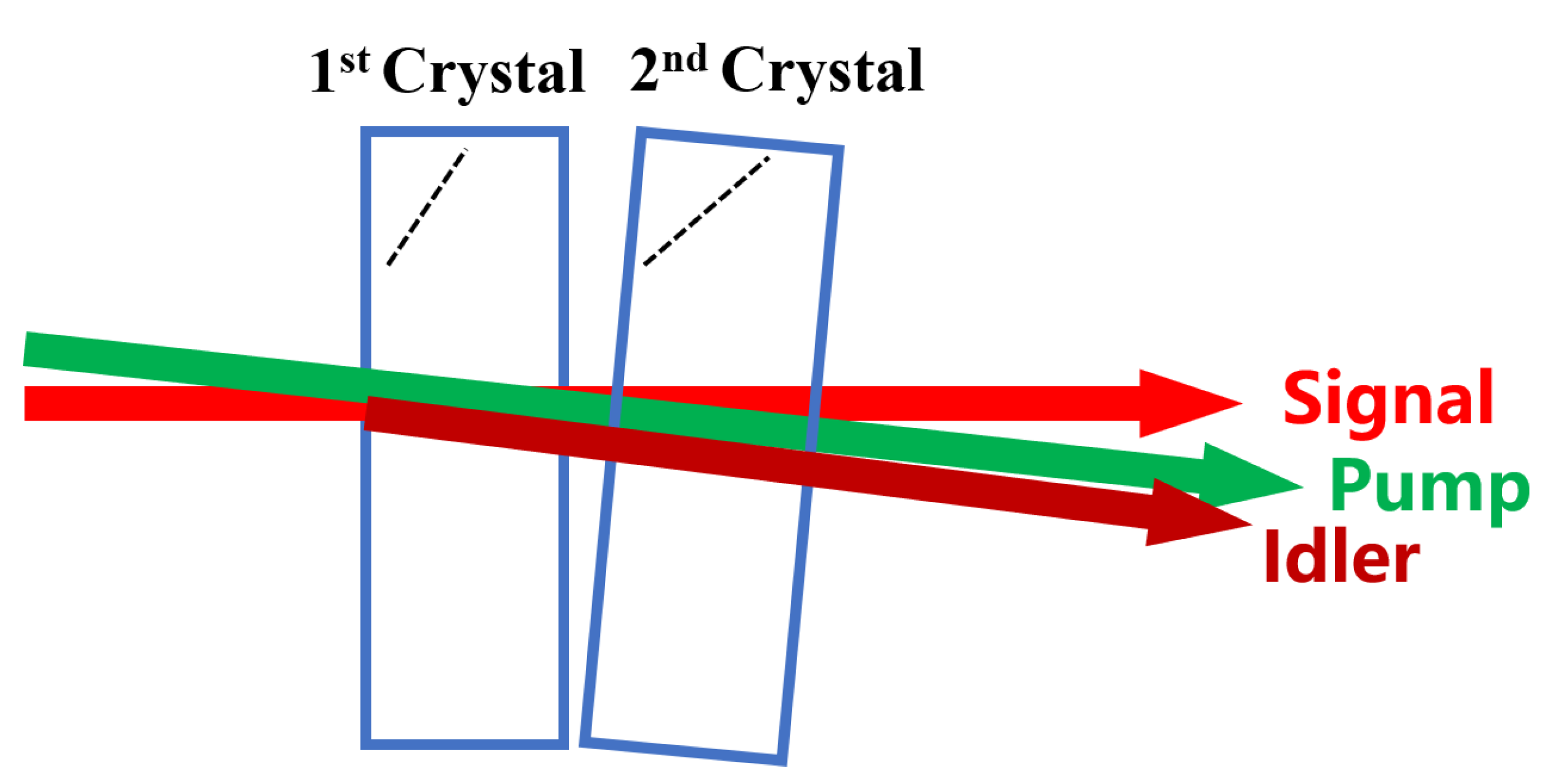
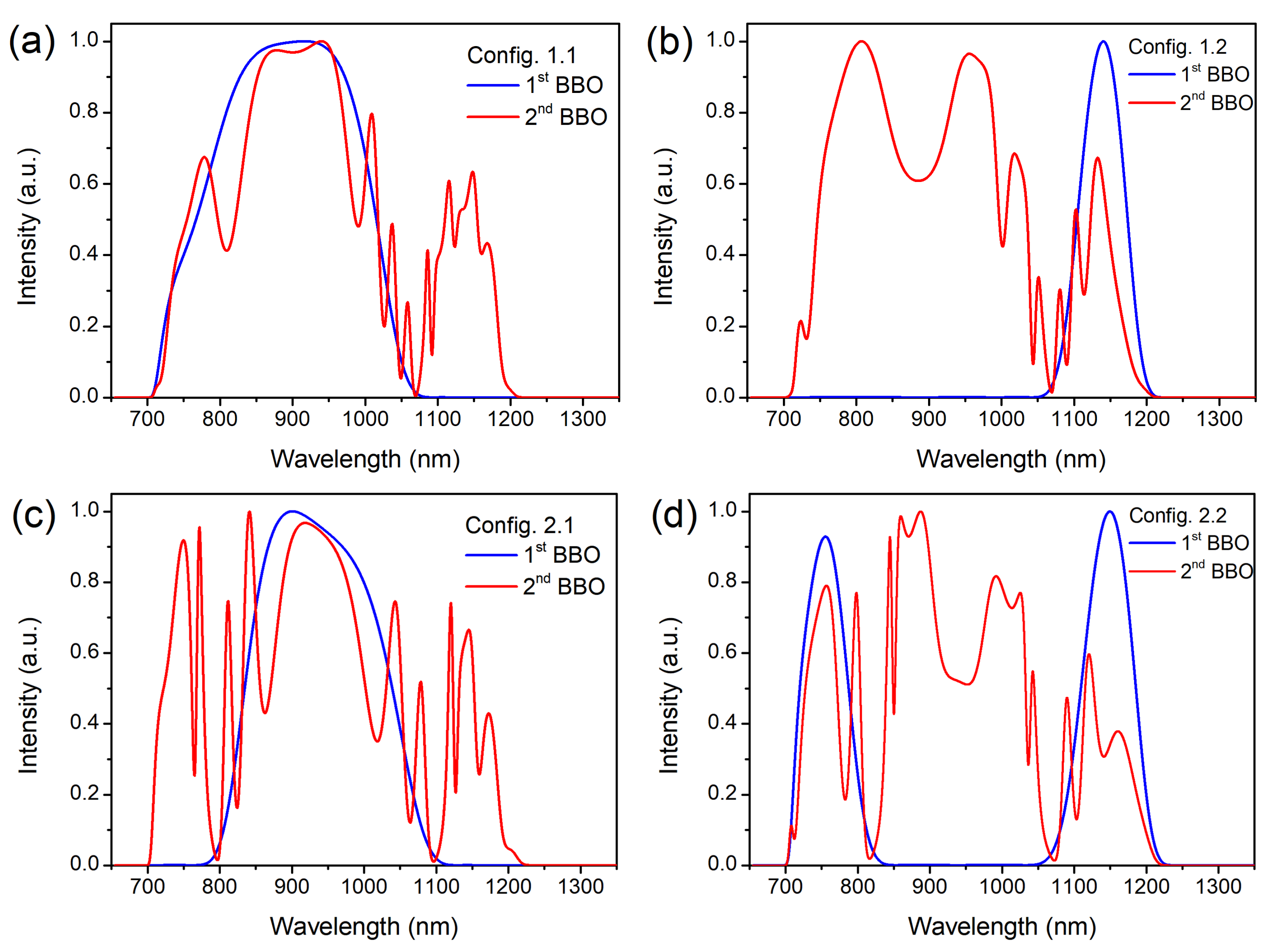
3.2. Temporal Contrast in the Compact Double BBO Arrangement

The compact double BBO arrangement is depicted in Figure 4. In this arrangement, two same-cut crystals are placed closely and the idler will not be depleted in the process of amplification. The pump and signal facilitate the same non-collinear angle in two crystals but the phase matching angles are different by adjusting the orientation of crystals. Consequently, different spectral components are amplified in series thereby supporting a broader overall bandwidth. It would be particularly useful if it also maintains the high temporal contrast of OPCPA as shown in Section 3.1.
In this section, we will calculate the temporal contrast in four types of double BBO arrangements. Our goal is to achieve ultrabroad spectrum and high temporal contrast simultaneously and look for the optimal design. For demonstration, the typical parameters of the crystals in four schemes are listed in the Table 1. As we will see, Config 1.1 and Config 1.2 amplify the short and long wavelength part of the signal spectrum separately in the cascaded crystals. The difference of these two configurations is that the short wavelength part is firstly amplified in Config 1.1, while the long wavelength part is firstly amplified in Config 1.2. In Config 2.1 and Config 2.2, the central and outer part of the spectrum is amplified respectively in two crystals. These two schemes also differ only with respect to the amplification order of the spectrum. The parameters of the pump and seed are the same as those used in Section 3.1.
Figure 5a,b illustrates the amplified spectrum in Config 1.1 and Config 1.2. In both schemes, the bandwidth is successfully increased by 100 nm in the long wavelength region than the bandwidth under the traditional configuration as shown in Figure 3. The spectral oscillations in Figure 5 are caused by the recombination of the signal and idler [15]. The idler generated in the first BBO would interact with the signal in the second BBO and produce pump photons. In addition, this interaction is related to the huge phase mismatch, so the spectral oscillations are produced. These oscillations can be reduced by lowering the gain over the whole spectrum. What matters is that, even with a large gain, the temporal contrast better than 2 × 10 11 before the main pulse is preserved in Config 1.1, as shown in Figure 6a. It indicates that the ultrabroad spectrum ranging from 700 nm to 1200 nm and high temporal contrast can be simultaneously realized in Config 1.1. In addition, the temporal contrast of 9 × 10 11 at approximately 20 ps before the main pulse is achieved in Config 1.2. The deterioration of the temporal contrast in Config 1.2 could be understood as below. In order to avoid the deep dip of the overall spectrum, the little overlap of the two phase-matching spectrum in two crystals is inevitable. It follows that the PSF in the overlapped spectral region (i.e., the region around 1060 nm in Config 1.1 and Config 1.2) could gain much more energy after being amplified in the two crystals. This phenomenon is more evident for the central temporal part of PSF because in this temporal part the corresponding pump pulses have the highest pump intensity. In Config 1.1 the central temporal region of pump has been consumed in the first BBO, while in Config 1.2 this part of the pump has not been consumed in the first BBO but in the second BBO. As a result, PSF in Config 1.2 will be amplified efficiently in both crystals, and thus PSF in Config 1.2 would have a larger gain.
The spectrum ranging from 700 nm to 1200 nm is also achieved in Config 2.1 and Config 2.2, as illustrated in Figure 5c,d. As shown in Figure 6a, Config 2.1 has a better temporal contrast of 2 × 10 10 at 45 ps before the main pulse than Config 2.2 with the temporal contrast of 1 × 10 9 at 30 ps before the main pulse. Similar to the comparison between Config 1.1 and Config 1.2, the difference of the temporal contrast between Config 2.1 and Config 2.2 is because the former alignment consumes the central part of the pump in the first crystal, while the latter alignment consumes the outer part of the pump in the first crystal. However, although Config 2.1 is more preferred than Config 2.2, its level of the pedestal is still one order of magnitude higher than the level in Config 1.1. It is possibly due to the difference of two configurations. There are two spectral interacting regions between the cascade crystals in Config.2.1 and only one spectral interacting region in Config 1.1. As a result, the respective phase-matching spectrum of cascaded crystals in Config 2.1 needs to be closer to maintain the similar output energy compared with Config 1.1. It enables PSF around 800 nm and 1100 nm has more potential to be amplified efficiently after the two crystals in Config 2.1, which leads to the deterioration of the temporal contrast.
Among the above four discussed schemes, Config 1.1 performs best with the spectrum ranging from 700 nm to 1200 nm and the background level of 2 × 10 11 to the main pulse. The advantage of Config 1.1 is to consume the pump region with higher intensity in the first BBO and avoid too much spectral overlap in two cascaded crystals. As shown in Figure 6b, there is a negligible difference between the traditional single BBO arrangement and the double BBO arrangement in terms of the incoherent background. However, the inset of Figure 6b shows that Config 1.1 has a worse temporal contrast in the time window of −1.7 ps to 1.7 ps, which may be caused by the spectral modulation in the double BBO configuration.
A more realistic spectrum that is similar to the frontend output in [15] is also simulated for the single crystal configuration and Config 1.1 while keeping other parameters unchanged, as depicted in Figure 7. The result shows that the output temporal contrast seeded by a more realistic spectrum does not have obvious change compared with seeding an ideal spectrum discussed above.

4. Conclusions

Motivated by the promising applications of intense few-cycle laser pulses with high temporal contrast, we are devoted to studying the ps-OPCPA schemes. Among the current systems, short-pulse OPCPA has particular advantages especially for the ultrabroad bandwidth and the high temporal contrast. However, it does pose great challenges for designing and constructing pump lasers with the duration of approximately 1 ps. The compact double BBO arrangement attracts us most because of its relative simplicity and potential high-performance output ability. In this paper, we present the five-wave-coupled equations to simulate the broadband amplification of signal and PSF. This numerical method is very convenient for investigating the amplification of PSF with different phase-matching conditions. It is found that the amplified energy of PSF with perfect phase-matching is little higher than the case of PSF having the same phase mismatch with the signal. In addition, much attention is paid to the calculation of the temporal contrast in the double BBO arrangement. According to our simulation, it can be concluded that the temporal contrast as high as 2 × 10 11 and the ultrabroad spectrum ranging from 700 nm to 1200 nm can be simultaneously realized in the compact double BBO arrangement pumped by 100 ps pulses. Numerical investigation in this work provides the theoretical guide for designing ps-OPCPA with the double BBO arrangement.

Author Contributions

Conceptualization, H.C. and Y.X.; Data curation, X.C., X.Y. (Xihang Yang), F.W., X.Y. (Xiaojun Yang), J.G., J.Q. and Y.X.; Funding acquisition, Y.X. and Y.L. (Yuxin Leng); Investigation, H.C. and Y.X.; Methodology, H.C., J.H., X.W., P.B., Z.Z. and Y.L. (Yaqi Liu); Project administration, Y.X. and Y.L. (Yuxin Leng); Software, H.C. and J.H.; Supervision, Y.L. (Yuxin Leng); Validation, Y.X. and Y.L. (Yuxin Leng); Visualization, H.C.; Writing—original draft, H.C.; Writing—review and editing, Y.X. All authors have read and agreed to the published version of the manuscript.

Funding

This research was funded by the National Key Research and Development Program of China (2017YFE0123700); The Strategic Priority Research Program of the Chinese Academy of Sciences (XDB1603); National Natural Science Foundation of China (61925507); Program of Shanghai Academic Research Leader (18XD1404200); Shanghai Municipal Science and Technology Major Project (2017SHZDZX02); Shanghai Sailing Program (19YF1453100); Natural Science Foundation of Shanghai (20ZR1464600);Youth Innovation Promotion Association of the Chinese Academy of Sciences; International Partnership Program of Chinese Academy of Sciences (181231KYSB20200040).

Institutional Review Board Statement

Not applicable.

Informed Consent Statement

Not applicable.

Data Availability Statement

All of the data reported in the paper are presented in the main text. Any other data will be provided on request.

Conflicts of Interest

The authors declare no conflict of interest. The funders had no role in the design of the study; in the collection, analyses, or interpretation of data; in the writing of the manuscript, or in the decision to publish the results.

References

  1. Chini, M.; Zhao, K.; Chang, Z. The generation, characterization and applications of broadband isolated attosecond pulses. Nat. Photonics 2014, 8, 178–186. [Google Scholar]
  2. Mondal, S.; Shirozhan, M.; Ahmed, N.; Bocoum, M.; Boehle, F.; Vernier, A.; Haessler, S.; Lopez-Martens, R.; Sylla, F.; Sire, C.; et al. Surface plasma attosource beamlines at ELI-ALPS. J. Opt. Soc. Am.-Opt. Phys. 2018, 35, A93–A102. [Google Scholar] [CrossRef]
  3. Gilbertson, S.; Wu, Y.; Khan, S.D.; Chini, M.; Zhao, K.; Feng, X.; Chang, Z. Isolated attosecond pulse generation using multicycle pulses directly from a laser amplifier. Phys. Rev. A 2010, 81, 43810. [Google Scholar] [CrossRef] [Green Version]
  4. Yavuz, I.; Altun, Z.; Topcu, T. Wavelength scaling of high-order-harmonic-generation efficiency by few-cycle laser pulses: Influence of carrier-envelope phase. Phys. Rev. A 2012, 86, 43836. [Google Scholar] [CrossRef]
  5. Nerush, E.N.; Kostyukov, I.Y. Carrier-Envelope Phase Effects in Plasma-Based Electron Acceleration with Few-Cycle Laser Pulses. Phys. Rev. Lett. 2009, 103, 35001. [Google Scholar] [CrossRef] [PubMed]
  6. Rácz, P.; Irvine, S.E.; Lenner, M.; Mitrofanov, A.; Baltuška, A.; Elezzabi, A.Y.; Dombi, P. Strong-field plasmonic electron acceleration with few-cycle, phase-stabilized laser pulses. Appl. Phys. Lett. 2011, 98, 111116. [Google Scholar] [CrossRef]
  7. Fülöp, J.A.; Major, Z.; Henig, A.; Kruber, S.; Weingartner, R.; Clausnitzer, T.; Kley, E.B.; Tunnermann, A.; Pervak, V.; Apolonskiy, A.; et al. Short-pulse optical parametric chirped-pulse amplification for the generation of high-power few-cycle pulses. New J. Phys. 2007, 9, 438. [Google Scholar] [CrossRef] [Green Version]
  8. Kessel, A.; Leshchenko, V.E.; Jahn, O.; Krüger, M.; Münzer, A.; Schwarz, A.; Pervak, V.; Trubetskov, M.; Trushin, S.A.; Krausz, F.; et al. Relativistic few-cycle pulses with high contrast from picosecond-pumped OPCPA. Optica 2018, 5, 434–442. [Google Scholar] [CrossRef]
  9. Kretschmar, M.; Tuemmler, J.; Schütte, B.; Hoffmann, A.; Senfftleben, B.; Mero, M.; Sauppe, M.; Rupp, D.; Vrakking, M.J.J.; Will, I.; et al. Thin-disk laser-pumped OPCPA system delivering 4.4 TW few-cycle pulses. Opt. Express 2020, 28, 34574–34585. [Google Scholar] [CrossRef]
  10. Fattahi, H.; Alismail, A.; Wang, H.; Brons, J.; Pronin, O.; Buberl, T.; Vamos, L.; Arisholm, G.; Azzeer, A.M.; Krausz, F. High-power, 1-ps, all-Yb:YAG thin-disk regenerative amplifier. Opt. Lett. 2016, 41, 1126–1129. [Google Scholar] [CrossRef]
  11. Jung, R.; Tümmler, J.; Will, I. Regenerative thin-disk amplifier for 300 mJ pulse energy. Opt. Express 2016, 24, 883–887. [Google Scholar] [CrossRef]
  12. Herrmann, D.; Veisz, L.; Tautz, R.; Tavella, F.; Schmid, K.; Pervak, V.; Krausz, F. Generation of sub-three-cycle, 16 TW light pulses by using noncollinear optical parametric chirped-pulse amplification. Opt. Lett. 2009, 34, 2459–2461. [Google Scholar] [CrossRef]
  13. Witte, S.; Zinkstok, R.; Wolf, A.; Hogervorst, W.; Ubachs, W.; Eikema, K. A source of 2 terawatt, 2.7 cycle laser pulses based on noncollinear optical parametric chirped pulse amplification. Opt. Express 2006, 14, 8168–8177. [Google Scholar] [CrossRef] [Green Version]
  14. Rivas, D.E.; Borot, A.; Cardenas, D.; Marcus, G.; Gu, X.; Herrmann, D.; Xu, J.; Tan, J.; Kormin, D.; Ma, G.; et al. Next Generation Driver for Attosecond and Laser-plasma Physics. Sci. Rep. 2017, 7, 5224. [Google Scholar] [CrossRef] [PubMed] [Green Version]
  15. Toth, S.; Stanislauskas, T.; Balciunas, I.; Budriunas, R.; Adamonis, J.; Danilevicius, R.; Viskontas, K.; Lengvinas, D.; Veitas, G.; Gadonas, D.; et al. SYLOS lasers–The frontier of few-cycle, multi-TW, kHz lasers for ultrafast applications at extreme light infrastructure attosecond light pulse source. J. Phys. Photonics 2020, 2, 45003. [Google Scholar] [CrossRef]
  16. Zheng, J.; Zacharias, H. Design considerations for a compact grism stretcher for non-collinear optical parametric chirped-pulse amplification. Appl. Phys. B 2009, 96, 445–452. [Google Scholar] [CrossRef]
  17. Dou, T.H.; Tautz, R.; Gu, X.; Marcus, G.; Feurer, T.; Krausz, F.; Veisz, L. Dispersion control with reflection grisms of an ultra-broadband spectrum approaching a full octave. Opt. Express 2010, 18, 27900–27909. [Google Scholar] [CrossRef] [PubMed] [Green Version]
  18. Tavella, F.; Nomura, Y.; Veisz, L.; Pervak, V.; Marcinkevicius, A.; Krausz, F. Dispersion management for a sub-10-fs, 10 TW optical parametric chirped-pulse amplifier. Opt. Lett. 2007, 32, 2227–2229. [Google Scholar] [CrossRef]
  19. Verluise, F.; Laude, V.; Cheng, Z.; Spielmann, C.; Tournois, P. Amplitude and phase control of ultrashort pulses by use of an acousto-optic programmable dispersive filter: Pulse compression and shaping. Opt. Lett. 2000, 25, 575–577. [Google Scholar] [CrossRef] [PubMed]
  20. Baudisch, M.; Pires, H.; Ishizuki, H.; Taira, T.; Hemmer, M.; Biegert, J. Sub-4-optical-cycle, 340 MW peak power, high stability mid-IR source at 160 kHz. J. Opt. 2015, 17, 94002. [Google Scholar] [CrossRef]
  21. Sosnowski, T.S.; Stephens, P.B.; Norris, T.B. Production of 30-fs pulses tunable throughout the visible spectral region by a new technique in optical parametric amplification. Opt. Lett. 1996, 21, 140–142. [Google Scholar] [CrossRef]
  22. Louisell, W.H.; Yariv, A.; Siegman, A.E. Quantum Fluctuations and Noise in Parametric Processes. I. Phys. Rev. 1961, 124, 1646–1654. [Google Scholar] [CrossRef] [Green Version]
  23. Mikhailova, J.M.; Buck, A.; Borot, A.; Schmid, K.; Sears, C.; Tsakiris, G.D.; Krausz, F.; Veisz, L. Ultra-high-contrast few-cycle pulses for multipetawatt-class laser technology. Opt. Lett. 2011, 36, 3145–3147. [Google Scholar] [CrossRef]
  24. Manzoni, C.; Moses, J.; Kärtner, F.X.; Cerullo, G. Excess quantum noise in optical parametric chirped-pulse amplification. Opt. Express 2011, 19, 8357–8366. [Google Scholar] [CrossRef] [PubMed] [Green Version]
  25. Li, Z.; Tsubakimoto, K.; Yoshida, H.; Uesu, T.; Tsuji, K.; Miyanaga, N. Spatial asymmetry of optical parametric fluorescence with a divergent pump beam and potential applications. Opt. Express 2017, 25, 7465–7474. [Google Scholar] [CrossRef]
  26. Stanislauskas, T.; Balčiūnas, I.; Tamuliene, V.; Budriūnas, R.; Varanavičius, A. Analysis of parametric fluorescence amplified in a noncollinear optical parametric amplifier pumped by the second harmonic of a femtosecond Yb:KGW laser. Lith. J. Phys. 2016, 56. [Google Scholar] [CrossRef]
  27. Wang, B.; Zou, X.; Jing, F. Quantum analysis of optical parametric fluorescence in the optical parametric amplification process. J. Opt. 2015, 17, 75503. [Google Scholar] [CrossRef]
  28. Tavella, F.; Marcinkevicius, A.; Krausz, F. Investigation of the superfluorescence and signal amplification in an ultrabroadband multiterawatt optical parametric chirped pulse amplifier system. New J. Phys. 2006, 8, 219. [Google Scholar]
  29. Moses, J.; Huang, S.; Hong, K.; Mücke, O.D.; Falcão-Filho, E.L.; Benedick, A.; Ilday, F.O.; Dergachev, A.; Bolger, J.A.; Eggleton, B.J.; et al. Highly stable ultrabroadband mid-IR optical parametric chirped-pulse amplifier optimized for superfluorescence suppression. Opt. Lett. 2009, 34, 1639–1641. [Google Scholar] [CrossRef] [Green Version]
  30. Cerullo, G.; Silvestri, S.D. Ultrafast optical parametric amplifiers. Rev. Sci. Instrum. 2003, 74, 1–18. [Google Scholar] [CrossRef]
  31. Zheng, J.; Zacharias, H. Non-collinear optical parametric chirped-pulse amplifier for few-cycle pulses. Appl. Phys. B 2009, 97, 765–779. [Google Scholar] [CrossRef]
  32. Gatti, A.; Wiedemann, H.; Lugiato, L.A.; Marzoli, I.; Oppo, G.L.; Barnett, S.M. Langevin treatment of quantum fluctuations and optical patterns in optical parametric oscillators below threshold. Phys. Rev. A 1997, 56, 877–897. [Google Scholar] [CrossRef]
  33. Homann, C.; Riedle, E. Direct measurement of the effective input noise power of an optical parametric amplifier. Laser Photonics Rev. 2013, 7, 580–588. [Google Scholar] [CrossRef]
  34. Stuart, N.; Bigourd, D.; Hill, R.; Robinson, T.; Mecseki, K.; Patankar, S.; New, G.; Smith, R. Direct fluorescence characterisation of a picosecond seeded optical parametric amplifier. Opt. Commun. 2015, 336, 319–325. [Google Scholar] [CrossRef] [Green Version]
Figure 1. (a) Phase-matching geometry of signal and (b) PSF. Signal can only be phase matched perfectly at the specific wavelength due to the fixed α . Fluorescence represented by the dashed line could have the feature of angular dispersion to meet the perfect phase-matching condition. We assume that the signal propagates along the z axis, and only fluorescence in the diffraction limit of signal is considered.
Applsci 12 00934 g001
Figure 2. (a) The signal energy and PSF energy versus the crystal length. The black line represents the signal energy. The blue line represents the PSF energy assuming that it has the perfect phase-matching condition. The red line represents the PSF energy assuming that it has the same phase mismatch with signal. (b) The signal-to-noise energy ratio (SNR) versus the crystal length. The blue line represents the case that PSF has perfect phase-matching condition. The red line represents the case that PSF has the same phase mismatch with signal.
Applsci 12 00934 g002
Figure 3. (a) Temporal contrast by compressing the signal to the Fourier transform limited duration at the crystal length of 3.5 mm, 4 mm and 5 mm; (b) Seed spectrum and the amplified signal spectrum at the crystal length of 3.5 mm.
Applsci 12 00934 g003
Figure 4. Compact double BBO arrangement.
Applsci 12 00934 g004
Figure 5. (a) Cascaded spectrum in Config 1.1, (b) in Config 1.2, (c) in Config 2.1 and (d) in Config 2.2. The blue and red line represent the spectrum at the exit of the first and the second BBO crystal respectively.
Applsci 12 00934 g005
Figure 6. (a) Temporal contrast in Config 1.1 (blue), Config 1.2 (orange), Config 2.1 (purple) and Config 2.2 (red). (b) Temporal contrast in traditional one BBO arrangement (pink) and Config 1.1 (blue).
Applsci 12 00934 g006
Figure 7. (a) A more realistic input spectrum (orange) and the amplified spectrum in the traditional single BBO configuration (pink) and in Config 1.1 (blue); (b) Temporal contrast in the traditional single BBO arrangement (pink) and Config 1.1 (blue) with a more realistic input spectrum.
Applsci 12 00934 g007
Table 1. Parameters of cascaded configurations.
ParametersConfig 1.1Config 1.1Config 2.1Config 2.2
Noncollinear angle ( )2.3042.3042.0792.079
Phase-matching angle of the 1 st BBO ( )23.7323.4623.5323.31
Length of the 1 st BBO (mm)3.53.73.53.7
Phase-matching angle of the 2 nd BBO ( )23.4623.7323.3123.53
Length of the 2 nd BBO (mm)4.13.63.63.6
Output energy (mJ)4.44.24.33.9
Publisher’s Note: MDPI stays neutral with regard to jurisdictional claims in published maps and institutional affiliations.

