
Eye-Tracking in Interactive Virtual Environments: Implementation and Evaluation


1
Department of Geography, Faculty of Science, Masaryk University, Kotlářská 267/2, 611 37 Brno, Czech Republic
2
Department of Educational Sciences, Faculty of Arts, Masaryk University, Arna Nováka 1, 602 00 Brno, Czech Republic
3
Department of Information and Library Studies, Faculty of Arts, Masaryk University, Arna Nováka 1, 602 00 Brno, Czech Republic
4
Institute of Psychology, Freie Universität Berlin, Kaiserswerther Straße 16-18, 14195 Berlin, Germany
*
Author to whom correspondence should be addressed.
Appl. Sci. 2022, 12(3), 1027; https://0-doi-org.brum.beds.ac.uk/10.3390/app12031027
Submission received: 4 December 2021
/
Revised: 10 January 2022
/
Accepted: 17 January 2022
/
Published: 19 January 2022
(This article belongs to the Topic Virtual Reality, Digital Twins, the Metaverse)
Abstract
:Not all eye-tracking methodology and data processing are equal. While the use of eye-tracking is intricate because of its grounding in visual physiology, traditional 2D eye-tracking methods are supported by software, tools, and reference studies. This is not so true for eye-tracking methods applied in virtual reality (imaginary 3D environments). Previous research regarded the domain of eye-tracking in 3D virtual reality as an untamed realm with unaddressed issues. The present paper explores these issues, discusses possible solutions at a theoretical level, and offers example implementations. The paper also proposes a workflow and software architecture that encompasses an entire experimental scenario, including virtual scene preparation and operationalization of visual stimuli, experimental data collection and considerations for ambiguous visual stimuli, post-hoc data correction, data aggregation, and visualization. The paper is accompanied by examples of eye-tracking data collection and evaluation based on ongoing research of indoor evacuation behavior.
1. Introduction
Researchers are generally fond of valid, reliable measurement methods and tools that allow the capture of variables containing rich information and high interpretative value. Eye-tracking may be considered such a profitable method because it captures eye movements and their derived patterns and finds application in the analysis of many types of spatial and visual compositions.
1.1. The Argument for Eye-Tracking
One could argue that the measurement variables acquired by eye-tracking have broad applicability, especially in cognitive science and its applications. The argument defines two types of variables: extrinsic and intrinsic variables [1]. Extrinsic variables (e.g., size) can be measured straightforwardly without the need for expert knowledge in constructing or operating the measuring instrument, whereas intrinsic variables are more challenging to access and measure, as their measurement tools make use of other variables or physics-based conversions to acquire the intrinsic value (e.g., measurement of blood pressure). In addition, not all phenomena can be measured by a device situated in the physical realm; for example, stress levels are not only expressed physically by blood pressure, heartbeat, pupil dilation, etc., but also by high-level cognitive and neurological factors such as stimulus habituation, nervous system excitability, etc. These are called constructs [2] and generally involve cognitive processing, and unlike variables, are not necessarily expressed by a singular quantitative value.
Therein lies the utility of eye-tracking: not only can it measure eye movements indirectly (non-invasively), i.e., intrinsically, it also lies at the threshold between variables and constructs. A raw data set of gaze coordinate entries (i.e., where a person looks at through a series of time segments) can be extrapolated into visual focus on stimuli (fixations), sequences of such focus (fixation scanpath and fixation revisits), and, subsequently, to provide an understanding of cognitive processing of a given visual scenery [3]. In general, the length of eye-tracking fixations, the objects that are fixated, the scanpath, and the frequency of fixation revisits all provide an insight into a person’s cognitive processing (e.g., task difficulty and task-solving strategy). In specific eye-tracking tasks (e.g., scene perception, visual search, reading, and task-driven action), eye patterns exhibited by users can be analyzed in further detail depending on the task methodology. In some instances, other findings can be extracted from eye movements and eye physiology—e.g., different cognitive styles or abnormal personalities [4,5,6]. Given that the eyes are an outward extension of the brain [7], and that many nonverbal [8] and physiological signals [9] are communicated through them and different processing patterns are used for different visual stimuli [10,11], they are useful data to obtain. These data can also be built on in future and in emerging technologies such as artificial intelligence [12], computer graphics, and virtual reality [13].
1.2. Eye-Tracking in VR
The present paper explores the possible interpretative value provided by eye-tracking in combination with VR technology. To describe the utility and potential of this combination of methods, an insight into their respective technologies follows.
While research into eye-tracking has a history of around a hundred years, it has only gained traction over the last four decades because the technology has matured into relatively simple to use, and easily interpretable, tools. The very first eye-tracking solutions were crude, painful extrinsic measures, which attached direct pen-like transcribers to the eyeball. In 1935, Buswell published a major eye-tracking study based on manual transcription of eye movements captured on film [14,15]. Indirect eye-tracking based on tracking light reflections in the eye, also known as Purkinje images [16], was first implemented in the 1970s and 1980s [17]. This technology uses the infrared light spectrum to obtain pupil center corneal reflections (PCCR), and is the most used eye-tracking method to this day.
Mobile eye-trackers also have a history, albeit a significantly shorter one. Given the technical requirements for processing corneal reflection video feeds and video encoding in such a small mobile device, the technology first had to miniaturize and improve power and performance [18,19] before it became a feasible tool. Mobile eye-trackers have therefore emerged only in the last decade or so; although, they are still less accurate and have less performance in frames per second captured compared to their stationary counterparts.
Along with its application in video-capturing mobile glasses [20], mobile eye-tracking technology has also been implemented in VR headsets. This coincides with the so-called “virtual reality revolution” of the current generation of VR headsets [21,22]. The first viable VR headsets of this generation appeared in 2013–2016 (Oculus Rift DK1 and DK2, and the first HTC Vive), and the first VR eye-trackers followed in 2016 (SMI VR ET addon to the abovementioned headsets). Currently, several vendors offer either inbuilt eye-trackers in VR headsets of their own production or eye-tracking add-ons intended as extensions to existing VR headsets. Advancements in 3D graphics rendering and VR display technology [23] allow the visual quality of VR displays to approach the physiological limits of human visual perception.
What is the practical utility in combining VR and eye-tracking? Perhaps it is the synergy of this combination. VR is known for its ability to render visuals of projected, proposed, or imaginary spaces [24,25], and facilitate interactivity with these imaginary worlds [26] and other people [27]. VR can thus transcend the limitations of time and space. Once the VR visuals are rendered, they can be combined with eye-tracking for numerous purposes, for example, validation of the spatial arrangement of a virtual environment [28] or user behavior in a virtual scene [29], reduction in graphics performance requirements by applying foveated rendering [30], or the use of eye-tracking as an interactive interface [31].
This can be effected at a fraction of the cost of preparing a real scenario. The software and application program interfaces (APIs), which facilitate graphics processing, and rendering and spatial algorithms are also computed relatively quickly, some even in real-time. Real spatial data, pre-made 3D objects, and graphics pipeline workflows [32] can be employed to create plausible virtual spatial compositions that can be supplemented with spatial data visualizations and evaluations [33,34].
1.3. Current State of the Research Field
The topic of eye-tracking data processing and interpretation is complex. Eye physiology must be considered, and algorithms must be built around it [35]. When eye-tracking is applied in virtual 3D space, new layers of complexity are introduced. Virtual space itself is accessible through interaction metaphors executed in real-world user interfaces. In the virtual world, the eye-tracked gaze is non-deterministically projected from the real world into the virtual world as the user moves about. Dynamic and interactive objects in a virtual scene can further complicate the interpretability of the given visuals. Suitable designs of VR experimental scenes that employ eye-tracking should therefore be considered, and the resulting eye-tracking challenges in evaluating the gaze in VR require a solution.
Prior research [36] and 3D industry implementations have considered some of these issues. Lappi discusses the problems of eye-tracking in VR at a theoretical level [37]. Clay et al. demonstrated the basic use of eye-tracking in experimental VR settings; however, the study lacks an in-depth perspective of processing data in the 3D environment [38]. Tobii XR SDK enables eye-tracking in basic scenarios [31]. A unifying approach to solving the problems related to eye-tracking in 3D VR, however, is currently unavailable.
2. Methodological Issues
2.1. Eye-Tracking Technology Applied in VR
To establish the common ground in all video-based eye-tracking technology, whether VR or otherwise, the similarities in the hardware and software of most eye-trackers must first be examined.
The commonalities in the hardware include the type of technology used and the metrics for sampling rate, field of view, accuracy, and precision. Given the limited space of the interior of a VR headset, the eye-trackers used in VR employ tiny cameras that implement infrared PCCR, which is the most used eye-tracking technology today. The sampling rate, accuracy, and precision of all non-stationary eye-trackers, whether VR or mobile, is limited by the size, layout, and performance constraints of the hardware, resulting in worse parameters than stationary eye-trackers (eye-trackers used in VR sample at 75–120 Hz, at about 3–5 degrees of accuracy, whereas stationary eye-trackers are superior, sampling at, for example, 2000 Hz at 0.15 degrees of accuracy [39]). Most VR headsets use an LED display behind an optical lens to cover a visual field of 100–110 degrees to accommodate most of the clearly perceived human vision; the range covered by eye-trackers used in VR has greater limits due to the optical limits of the system [40].
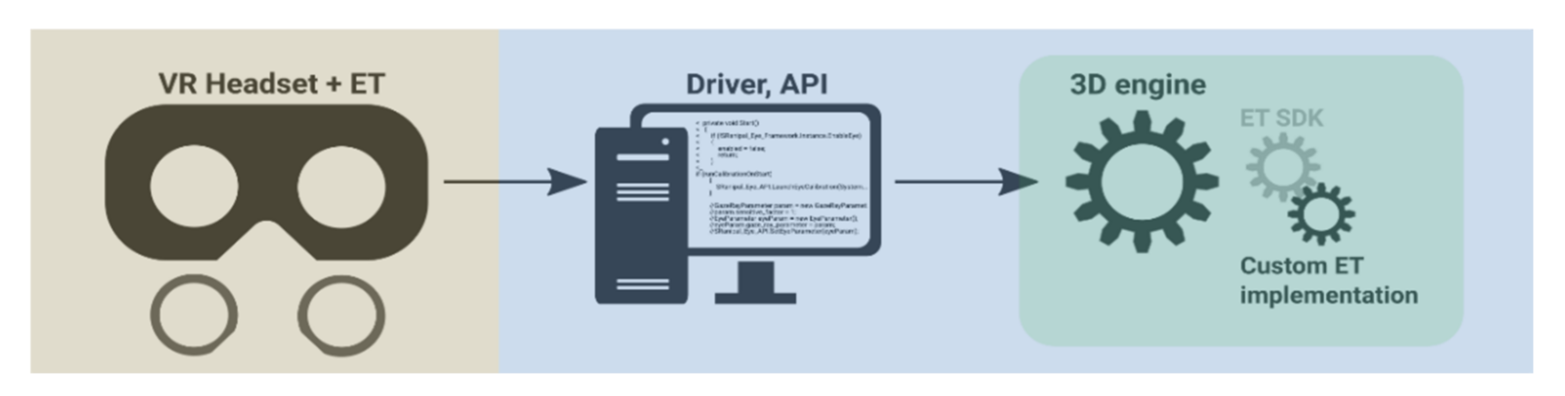
Eye-tracking software for VR (APIs, calibration procedures, and 3D engine extensions) is tailored to the virtual 3D world. The captured data contain two levels: the raw X/Y coordinate data, as captured through the eye-tracking cameras, and the transformed 3D data, as projected into the virtual world. Whether the raw data are accessible or correctible, and how it interfaces with third-party applications such as 3D engines, depends on the implementation of an eye-tracker API for VR or a 3D engine-specific software development kit (SDK) that draws functionality from the API. At the level of the 3D engine, it would be beneficial if the VR eye-tracking vendor provided an engine-specific SDK or a preconfigured extension (plugin) so that the API link between the eye-tracker and the engine would be well established, out of the box, with official support. This would allow the hardware-capable features to be utilized in the engine without the need for deep understanding of hardware and low-level programming to access the functionality. All Tobii XR eye-trackers (HTC Vive Pro Eye, Pico Neo 2/3 Eye, HP Reverb G2 Omnicept Edition) [31] and enterprise solutions such as VRgineers [41] and Varjo [42] provide engine-specific plugins for eye-tracking in VR. Behavioral data inputs, such as eye-tracking gaze, fixations, dwell time, and object-to-object transitions, can thus be both logged and used as a means of interacting with the objects in a virtual world. Custom programming functionality in 3D engines can expand on the eye-tracker’s extensions and functionality. All this, as depicted in Figure 1, provides a full picture of how an eye-tracking solution integrates with a 3D engine and a virtual world. The industry is even showing an inclination to develop standardized eye-tracking interfaces for VR [31] and SDKs [43].
2.2. Levels of Interpretation
Traditional 2D eye-tracking has two distinct levels of interpretation, one through eye-tracking coordinates (point of regard) and the other through defined areas of interest (AoI). As with eye-tracking in 2D, eye-tracking in 3D VR can observe coordinates in virtual 3D space (point of fixation (PoF)—a positional vector coordinate) and virtual 3D objects (as visually defined by 3D meshes). The informational value obtained from eye-tracking in 3D is similar to its 2D counterparts; although, differences exist because of the three-dimensionality of the virtual coordinates and the predefined surface area of the in-engine 3D meshes. Since the virtual 3D space is defined in exact mathematical coordinates, this allows for executing spatial algorithms on top of it.
A virtual 3D world is composed of virtual objects (3D objects and 3D meshes, depending on the terminology and technology of the 3D engine). The eye-trackable 3D objects have physics boundaries (collision geometry) attached to them. At a detailed interpretation level, the 3D gaze coordinate can be obtained when the user’s eye-tracking raycast hits the object collision geometry at a particular positional vector. At the simplified interpretation level, the information that a user is looking at the object, is aggregated.
The problem with 3D coordinate tracking is that the subsequent data filtering and analysis is demanding on the required implementation, algorithmization, and processing time. Similarly, the problem with 3D object tracking is loss in measurement accuracy and the inherent issues of object-based geometry, for example, the non-uniform sizes and scales of objects, their frequently illogical segmentation/separation, or their partial visibility in a scene.
Nevertheless, processing eye-tracking data from 3D VR at either the coordinate level or object level does not need to be antagonistic. One approach can complement the other, and hybrids can be implemented. This is discussed in the implementation section (e.g., fixation magnetism, distance-based object segmentation, and fixation algorithms).
2.3. The Complex World behind the Projection
The virtual world presented to a user through the VR headset display does not have any physical dimensionality. It is instead rendered onto the two-dimensional plane of a VR LED display. Depth perception of a virtual 3D world is maintained by simulating some of the visual cues present in the real world. Monocular visual cues that can be applied in 3D graphics include perspective, 3D lighting, and postprocessing filters for recomputing light occlusion and atmospheric perspective [44]. At this level, pseudo 3D level of depth perception is produced (e.g., as achieved by 3D graphics projected onto an LCD screen). By adding the binocular disparity visual cue, i.e., by shifting near object positions to the side for left/right display (as would be naturally perceived by the left/right eye in physical space), real 3D depth perception is attained.
Regardless of whether eye-tracking is stationary, mobile, or VR, or whether the stimulus is presented in 2D, pseudo 3D, or real 3D, eye-tracking device will always internally capture eye coordinates as 2D X/Y coordinates of the normalized projection plane where the capture commences (point of regard, PoR). The VR headset display is one such projection plane, and it serves as a portal between the real and the virtual world:
- Head movement is tracked by the VR headset (or a motion capture setup for whole body movement). Unless otherwise limited, its six degrees of freedom (6DoF) [45] allows direct rotation (3DoF) and movement (3DoF) in real space. User kinetic movement is translated directly into the virtual space, altering the camera’s rotation and position.
- Locomotion user interfaces allow translating movement into the virtual world—be it through abstraction, movement metaphors, or actual movement tracking. Up to six degrees of freedom are also possible, depending on the complexity and usability of the physical user interface (e.g., keyboard and mouse vs. a VR controller, treadmill, or other (experimental) devices [46]). There is a trade-off between the complexity of a locomotion user interface and the quality of sensory input it offers (e.g., keyboard facilitates on/off movement along one axis at a constant pace—it is a simple interface, but the lack of bodily kinesthetic feedback makes it susceptible to motion sickness [26]; a complex interface such as full-body motion capture allows for realistic, precise movement sensation—at a cost of setting up the interface, physical space demands, and significant purchasing costs). Locomotion user interfaces influence users’ perceived ease of movement and distance estimation [47]; they can even facilitate new ways of working with digital content [48,49]. They may also influence viewing behavior—this, however, has not been addressed in any research to date.
- Eye gaze coordinates are transformed into raycasts, which extend into the virtual world, i.e., by using the point of regard eye coordinate and camera position/rotation in the virtual world. As the ray is cast, it lands onto a spatial coordinate in the virtual world (point of fixation, PoF), provided something is in the ray’s path to land on (3D objects or surfaces).
In geometry and 3D engine terminology, a raycast is a beam with a positional vector origin and a directional vector angle [50]. In eye-tracking in VR, the origin is the virtual camera’s position and rotation as aligned by real-world user movement or the locomotion user interface, and the directional vector is the eye-tracking coordinate angle relative to the camera’s position/rotation. The specificity of processing and evaluating eye-tracking in 3D VR is dependent on the applied device(s), algorithm(s), and virtual environment(s). The transition to a virtual world is an extra calculation that traditional 2D eye-trackers need not be concerned about.
The validity and feasibility of eye-tracking analysis in 3D VR therefore becomes complicated (a greater number of measured and intervening variables, and variable transition rules). This complexity has various degrees, however, and was first described by Lappi [37]: while a stationary eye-tracker needs only to observe eye movements, such movements in VR may be occurring in addition to or counter to the user’s head or body movements (performed either directly, kinesthetically, or indirectly through a user interface), hand movements, user controller movements, interactions with other objects/users/entities in dynamic virtual scenes, and so on.
A stationary eye-tracker with a chinrest only tracks the user’s eyeballs, which move along two axes and have a limited angular range of rotation and can only be projected against a fixed observed plane. Mobile eye-trackers may have to account for changing surroundings while the user moves about. Beyond the physical dimension, if a subject is rendered in VR, the projection must be converted, for example, by translation of the virtual coordinates into seemingly physical ones. Some stationary VR experiences have limited or no degrees of freedom, for example, 360 video or driving simulators [51]. Many VR devices, however, make full use of the mobility aspect to utilize the full potential of VR as a medium [52]. Eye-tracking in VR scenarios is therefore interpretation-heavy. Below is a description of the interpretation complexity in scenes when considering two control variables:
- Static camera, static scene. The VR user observes the virtual world through a stationary, immovable virtual camera with zero degrees of freedom, and the only registered physical movement is eye movement. The user’s eye movements have no dynamic or interactive function attached, effectively equating this interpretation level to that of traditional 2D eye-tracking with static stimuli and the user resting on a chinrest. This is the simplest eye-tracking interpretation level, as the point of regard is the only relevant variable. The point of fixation transition is unnecessary since all the virtual coordinates seen on the screen are the only coordinates there are. Even if the presented scene is a 3D visualization with varying depth, the point of regard data set will always be transformed to the same point of fixation data set, with 1:1 projection. The acquired data can therefore be reduced to point of regard or worked with as if the stimulus were a static 2D image.Level of interpretation complexity: eye coordinates over time.
- Static camera, dynamic scene. The user has no control over the virtual camera position or rotation, giving them no possibility to change the perspective from which the presented stimuli are seen. The experimental scene can, however, dynamically change in front of the user’s eyes. In 3D, this would involve a predefined animation or other actors (AI, or other users with dynamic movement enabled). In classic eye-tracking studies, this can be equated to presenting a video. The majority of experimental control is still retained, i.e., the camera’s rotation/position is shown through the virtual camera, but knowing which content is shown, and the order in which it is shown, depends on whether the dynamics are deterministic (e.g., predefined animation vs. another user with dynamic controls). Regardless, this type of scene must be evaluated frame-by-frame. In these types of continuous scene, the positions of objects and their AoI coordinates change in time.Level of interpretation complexity: eye coordinates over time with scene movement.
- Dynamic camera, static scene. All interaction occurring in this type of scene is movement interaction [52], i.e., the user manipulates the virtual camera. The degree of complexity in recording and evaluating such movement increases significantly since the researcher abdicates control of the camera to the user, and thereby loses control of what is shown to the user, when it is shown, the order in which it is shown, from what angle and distance it is shown, and the overall scene composition. The user’s ability to navigate through the virtual scene depends on the physical controller and how the physical controller translates into the virtual scene (in-engine character controller [53]), and how many degrees of freedom such a controller provides, i.e., whether the camera can be rotated and moved and the extent of this movement. Even with simple camera dynamics, the three-dimensionality of a scene, i.e., the virtual space coordinates at and from which the user looks, and the distance between the user camera and the point of regard, must be considered for eye-tracking evaluation purposes. Free movement of the camera may cause 3D objects to occlude other objects, creating difficulties in interpretation [54]. Given the rather low precision of VR eye-trackers, measurement artifacts can originate at the border of multiple neighboring objects. The depth irregularity of a 3D scene and the potential measurement error is also projected irregularly onto objects in the 3D scene (objects at greater/varying distances accumulate more absolute-distance measurement errors than near objects of similar size since the eye-tracking precision error is based on angles, and the absolute distances between angle-based raycasts increase with depth). This level of eye-tracking complexity in 3D VR has no parallel in traditional eye-tracking in 2D.Level of interpretation complexity: eye movements over time with user movement and scene movement (synchronously).
- Dynamic camera, dynamic scene. All the interpretation issues mentioned above apply to this classification. In this case, other actors besides the user can also manipulate the projection and composition of the scene. At the user interaction level, these may be other (concurrent) user interfaces, controllers, or interaction metaphors, which allow selection, manipulation, systemic control, or symbolic input. Scene manipulation may occur at the level of individual objects, groups of objects [52], or the entire virtual scene [55]. At the execution level, events happening in the scene may be user-driven (interaction) or autonomous (AI or script-based), with or without feedback (visible, audible, or unregistrable), with or without affordances [56], (communicating or not communicating to the user that events or objects are potentially (inter)actible). Other users (multiplayer), AI, or interactive scripts may also instill changes within the scene. All these factors raise a new set of computational and visualization questions in the interpretation and visualization of a series of point of regard coordinates that target moving objects (especially when the user is concurrently moving in a different direction, or using a different controller).Level of interpretation complexity: eye movements over time with user movement and scene movement (asynchronously or a multitude of concurrent movements).
The examples as described above of a static, fixed user and a dynamic, moving user who observes a complex virtual scene, are depicted below in Figure 2, sourced from Lappi [37]. These examples do not consider the dynamics of the stimulus, regardless of whether it is a flat 2D video or an interactive multi-actor 3D scene. The movement diagram depicted by Lappi does not include other devices (e.g., motion controllers) with their own fields of reference.
Beyond research interests and theoretical approaches, the potential and limitations of eye-tracking in VR are also applicable in practical implementation, i.e., in algorithms and the optimization, evaluation, and visualization of VR eye-tracking data in virtual 3D scenarios. Previous studies and implementations have considered this only to an extent. The present paper regards implementation as its principal contribution. A discussion and demonstration are given in the following sections.
2.4. The State of Other Implementations
Other studies and implementations of eye-tracking in VR should also be considered to determine their links with the theory described above, and whether they are able to solve the aforementioned issues. Unfortunately, only a few solutions exist for comparison, and we are reluctant to apply these existing implementations because they interpret eye-tracking data at a rather shallow level or in specific, easy-to-interpret scenarios, only.
A 2018 study [57] employs eye-tracking in VR but reduces all evaluated eye-tracking data to those observed on a flat orthogonal wall in front of a user (effectively staying in the realm of traditional 2D eye-tracking). A 2019 study [37] goes further by visualizing the raycastHit.hit coordinate returned by a basic projection function in the Unity engine API. This is the 3D coordinate where the raycast hits an object collision geometry. The authors visualized this with a sphere, and then colored the sphere according to the distance from which it was gazed upon (the raycastHit.distance numeric value according to the Unity API). The remainder of the article discussed working with this basic eye-tracking data using external statistics, visualization software, and user movement parameters. The in-engine eye-tracking data itself were not processed or corrected into derived variables, and therefore the specifics of eye-tracking methodology in VR, such as data filtering, scene complexity, or fixation processing, remained unaddressed.
The Tobii XR SDK, which is an extension of the SRanipal API used by some VR eye-trackers, implements some eye-tracking logging and visualization functionality [58], such as standard object-level data logging metrics (first dwell time, dwell time, and dwell count) and heatmap-based visualization projected onto supported objects using a dynamic graphics shader [59] to draw the gaze heatmap as an additive texture over already fixated objects/textures. While the solution behind this implementation does provide some value and ingenuity, it is only applicable to qualitative scenes with a low complexity in the 3D geometric variance, such as gazing at a static car object situated in the simple scene of a showroom. If eye-tracking is performed in an environment where, for example, a vast, dynamic cityscape with varying distances and overlapping vistas is present, using a heatmap-based eye-tracking visualization would not be practical or acceptable. Similar issues would arise when qualitative evaluation of the acquired eye-tracking data is intended.
The Vizard virtual reality software extension for researchers from WorldViz, SightLab VR [60] offers features similar to the aforementioned solutions (gaze intersections, fixations, fixations per object, average time of fixation, etc.), which are automatically logged to a text file. It also features a record function that lets the user replay certain sessions with graphical overlays of the gaze paths, fixations, fixation spheres, heatmaps, or intersect points. Vizard and SightLab VR, however, are developed as proprietary software, and hence the functions in the free version of Vizard are strictly limited, or in case of the SightLab VR, must be purchased.
The aim of the present paper is therefore to develop algorithms for eye-tracking in VR that facilitate data logging, filtering, correction, analysis, and visualization. This solution is to function with scenarios of high complexity, providing better methods of managing eye-tracking data in complex scenes, all while respecting the methodology.
3. Implementation
To give some context to VR eye-tracking algorithms that aid in dealing with the interpretative difficulties of virtual 3D environments, their unifying technological foundations should first be explained. This section therefore describes the technology we worked with, the software architecture and design of the proposed implementation, the process of obtaining and working with eye-tracking data, and the desired 3D scene setup for use in an eye-tracking experiment. Based on this foundation, the algorithms that can eliminate some of the issues with 3D VR eye-tracking data are described and implemented. Together with visualizations of the processed data, the solution is able to offer clearer interpretative value.
Partial software implementation of the VR eye-tracking solutions mentioned throughout this section are available at the following GitHub repository: https://github.com/VGE-lab-MUNI/vr-et, accessed on 16 January 2022. This is a demonstration implementation for the Unity engine version 2019 LTS and newer, using the HTC Vive Pro Eye VR headset and SRanipal API (the technology is explained in Section 3.1).
3.1. The Technology That Is Available and the Technology That Is Used
The technology applied in eye-tracking and VR forms a layered architecture consisting of VR and eye-tracking hardware and low-level drivers (firmware) to facilitate the hardware’s basic functionality. This translates into an operating system level driver and API used in a 3D engine. Additional work over the API can be tailored into a premade 3D engine extension to cut implementation costs for the users of the engine. In the end, a set of eye-tracking-related in-engine functions are made available for use.
Due to the current market fragmentation (many vendors of VR headsets, many third party vendors of VR eye-trackers, and multiple 3D engines), the future will likely include a standard for extended/virtual/mixed/augmented reality devices, i.e., multiple APIs under a single SDK [43] that interconnects the hardware with 3D engines and other applications. Standardization of eye-tracking for VR is also expected [61].
The inter-compatibility of devices under a single SDK is significant because it eliminates researcher dependence on a single hardware vendor or device. This is relevant, as hardware dependence could become an issue in ongoing research. For example, in long-term research design, the original vendor-centric hardware could become obsolete or unusable over time (lack of support, feature-breaking update, or hardware error). API/SDK standardization also enables designing and programming of eye-tracking evaluation scripts in a manner that allows their re-use, either immediately or with minor tweaks only, with different VR eye-trackers (within the constraints of the programming language of the selected 3D engine).
The present paper demonstrates an implementation and interpretation of eye-tracking for VR in a virtual indoor evacuation behavior experiment (to observe user decision-making and navigation strategies based on locomotion and eye-tracking). The experiment employed an HTC Vive Pro Eye headset with an integrated eye-tracker (Tobii). VR and eye-tracking functionality was enabled in the engine with the SteamVR application (as required for all HTC or Valve headsets) and applied with the SRanipal API for Tobii eye-trackers [62]. Upon importing the SRanipal API into Unity, the 3D engine of our choice, basic eye-tracking functionality, such as positional tracking and a calibration procedure, was available out of the box. The remainder was implemented using algorithms of our own design.
The currently most used 3D engines are Unreal engine [63] and Unity [64]. We selected Unity for the experiment. The criteria to determine the suitability of an engine to one’s (experimental) needs include the programming language and the range of functionality of the provided programming API, the customizability, scalability and extensibility of the engine and its scene editor, available extensions, supported 3D formats and available 3D model repositories, platform compatibility, and graphics fidelity. In other words, a 3D engine is a middleware with various functionalities and quality of life additions, and the end-product software (whether a research application or otherwise) should make the best use of the 3D engine’s features to reduce the potential implementation costs (man-hours, budget, workflows, or technical knowledge). Unity provides a C# programming language API, along with its own repository, Asset Store (to obtain editor extensions and 3D models). Comprehensive documentation is available, and it has the support of a strong community. However, the level of its graphics fidelity is lacking, in direct contrast with Unreal engine, which is written in C++, has a less widespread community, yet state-of-the-art graphics. It is noteworthy that Unreal engine has been driving advances in the 3D industry by providing feature additions and improvements such as a photogrammetric 3D object library [65], virtualized geometry [66], and a visual scripting language [67]. As such, the engine is well-established for excellence in the future.
Although we used Unity throughout the implementation phase of our paper, the examples are described in a manner so that they can be applied or implemented in other 3D engines.
3.2. The Program Architecture
The core of the proposed solution, as implemented partially in the Unity engine and partially by applying external scripts and applications (data log file processing and statistical analysis), is straightforward and in accordance with the intended program architecture. Most of the provided programming language classes are instantiated in engine run-time either as single instances (singletons) or script components attached to 3D objects existing in the virtual world. This is acceptable, since only one eye-tracking raycaster script, one data logger script, one data processing script, one data visualization script, etc., are required at a time. This also enables extensibility and interchangeability in the provided algorithms, and if the need arises, their reimplementation in other 3D engines.
The complexity of the implementation is evident from the eye-tracking algorithms. These must be optimized for efficiency, i.e., reasonable processing time and memory allocation. This applies especially to algorithms executed in real time, i.e., with a severely limited processing budget (a few milliseconds). Each algorithm must also follow the eye-tracking methodology and apply workarounds to its (and the engine’s) limitations.
Figure 3 illustrates the proposed program logic: experimental runtime and evaluation runtime. The program architecture of the proposed solution follows this logic because the two runtimes frequently apply algorithms that are oftentimes mutually exclusive.
Experimental runtime should be included in any experimental scenario purposed for data acquisition. The scenario should contain fully realized visuals in the virtual scene, a user controller logic allowing users to move around the environment or interact with their surroundings as intended, and a data logger script that produces the desired data outputs. The user experience here is critical: the user should perceive the experimental scenario as it was intended. Scene interactivity scripts and data logging should therefore be performed in the background, without disrupting the flow of the experience.
Evaluation runtime is an ex-post set of tools for researchers: i.e., for processing, visualizing, and verifying the movement, interaction, and eye-tracking data produced by the user. The runtime still contains the virtual experimental scenario (allowing the researchers to move through it), but data logging or user experience is not the intent. The user behavior data produced in experimental runtime are then loaded by the evaluation runtime for visualization or processing into aggregated values (then visualized or sent for statistical analysis). In addition, algorithms that are either inefficient for implementation in the experimental phase, too visually intrusive, non-relevant, or experiment-tampering, are applied and used here. These include eye-tracking fixation calculations in 3D space, eye-tracking correction algorithms, visualizations and projections of user behavior, visualization filtration, and user behavior replays.
3.3. Levels of Working with Eye-Tracking Data
Eye-tracking data can be acquired and reprocessed (recomputed and aggregated). This can be performed either non-destructively, by retaining the full information provided by the eye-tracker hardware, or destructively, by reducing the information resolution. This relies on obtaining data from the eye-tracking hardware, the ability to access the data through the eye-tracking API, and the in-engine implementation and virtual scene definition (explained in the following subsections).
What is the minimum required level of distinction in the acquired data for it to be fully useful for evaluation? That depends on the degrees of freedom of the provided VR hardware (the headset and controllers, if any). Generally, it requires:
- Eye-tracking calibration data (success/failure, or more detailed accuracy value);
- Timestamp for each log entry (time, up to milliseconds);
- User coordinates (positional Vector3 in the virtual world);
- User camera rotation (rotational Vector3 in the virtual world);
- Eye-tracking rotation relative to the user camera rotation or the point of fixation (Vector3).
This could be considered the bare minimum set of variables to be acquired during experimental runtime. Other derived variables may also be obtained. The question is whether it is better to acquire the derived variables during runtime (for convenience) or to recompute them later, outside experimental runtime (to conserve computational power during the runtime). At a minimum, these derived variables include:
- Eye-tracking rotation relative to the user camera rotation and point of fixation—both;
- Gazed 3D object name (object.name value);
- Gaze distance from the user camera to the point of fixation (in meters);
- Data loss metric, i.e., a check for missing eye inputs;
- Fixation metric, i.e., a check for whether eye-tracking fixation is occurring, based on the eye-tracker movement velocity and its near-time history, all relative to camera movement;
- Other potential physiological measurements of the eyes, if supported by the API (e.g., pupil dilation size or measurement accuracy);
- Other potential derived variables.
Beyond eye-tracking, experimental runtime can also process other algorithms. To measure user behavior, other logs can be produced, such as user movement logs, interface usage logs, interaction logs, etc. Such interaction logs (event logs) are important, as their execution (based on a temporal event, spatial event, etc.) allows segmentation of the eye-tracking data. An event log is a demarcation that states that from this event here until another event there, an experimental phase occurs, and, therefore, this eye-tracking data section is suitable for further extraction and processing.
3.4. Setting Up the 3D Environment for Eye-Tracking
Depending on the hardware, software, visual art direction/stylization, and intended scene use, various types of scenes can originate from a number of graphics pipelines and workflows [68]. A graphics pipeline takes into consideration the available rendering technology, for example, the rendering library, 3D modeling software, external sources like photogrammetry, AI-assisted pattern generation, and 3D engine scripting extensions. A graphics workflow is a set of agreed rules and best practices of working with the 3D sources and technologies in the context of a specific project, incorporating the 3D content into a scene in a (semi) streamlined fashion. Namely, a scene can be generated fully from the author’s imagination, while the opposite approach is the generation of a virtual scene strictly based on existing geometry (e.g., a replica of an existing real environment). An example of an approach situated between these two is the use of pre-generated 3D objects acquired from real geometry to produce layouts of new spatial compositions. Given the possibilities in graphics shaders and graphics post-processing [69], it is possible to visualize a scene in various styles, for example, realistic, semi-realistic, surrealistic, simplistic, and cartoonish. Depending on the artistic or research intentions of the creator, all these approaches and stylizations have some merit.
For the present paper, we created a digital substitute of an existing building based on its floor plan. The scene was then digitized into a 3D standard used in the construction industry, followed by porting into a 3D engine. The scene was originally created to serve as a digital copy of a real environment with the intent that an experiment could be run simultaneously in VR/real counterparts.
The virtual scene was created based on BIM (Building Information Modeling) documentation presented in the IFC data format. BIM is a commonly used digital representation of the physical and functional characteristics of a building’s entire life cycle, with a focus on large-scale details that are relevant in architecture, civil engineering, construction, and project management [70,71]. At the level of implementation, BIM is a container for five-dimensional data, which describes space, material type, and building changes through time. For 3D engine use, the format is excessive and requires simplification.
Because we initiated the conversion process from BIM to the Unity engine, the building’s model was converted from the IFC format to the Unity compatible DAE format using the Tridify Convert service [72]. The Unity editor was extended with the Tridify BIM Tools extension [73], which allowed conversion of the DAE data into standard 3D objects native to the Unity ecosystem. However, the imported 3D objects of the building did not satisfy the requirements for graphics fidelity, model organization, and model optimization. Many more manual optimizations were required before the 3D scene was usable in the subsequent eye-tracking experiment.
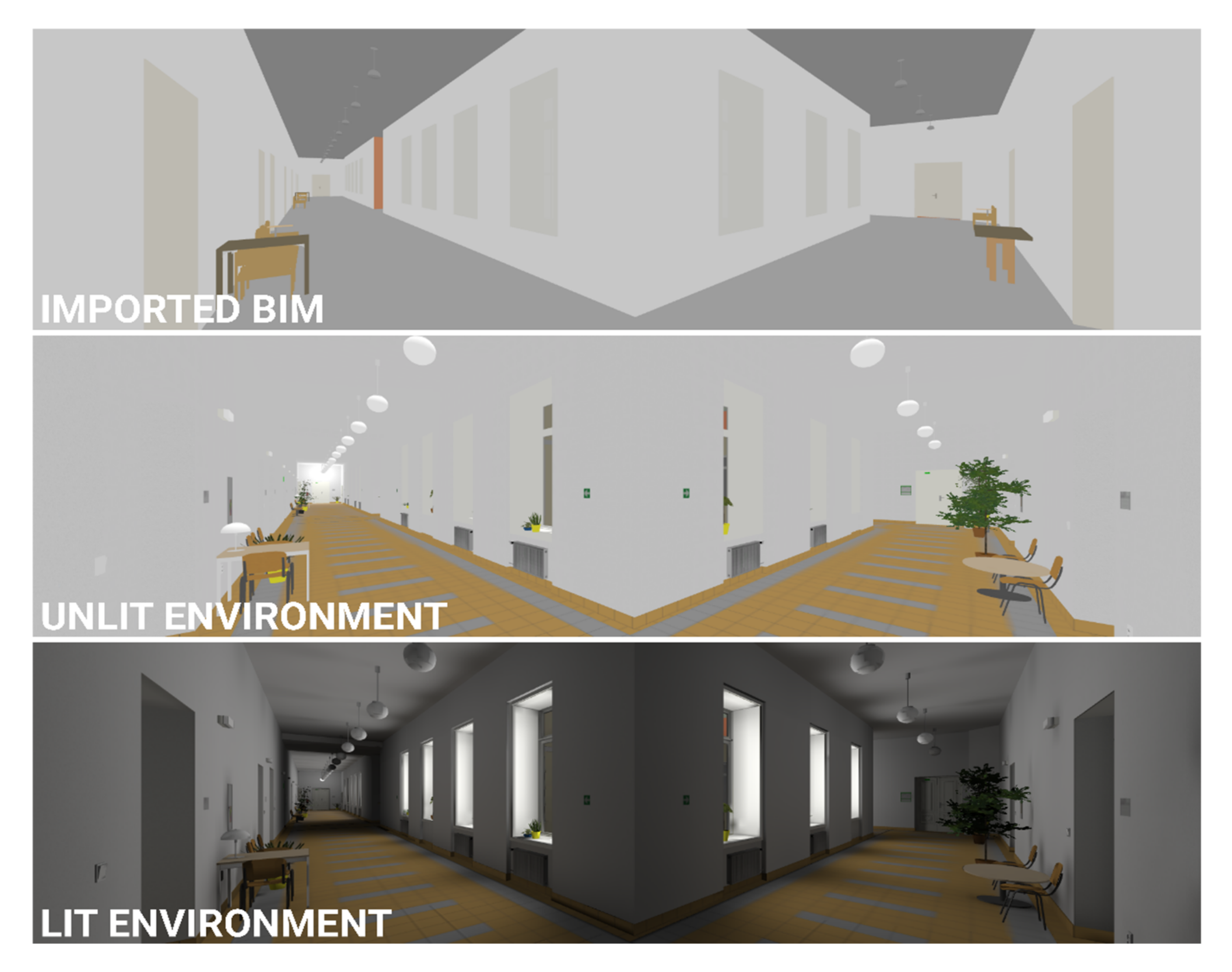
To objectively recreate the environment in high fidelity, we visited the physical site and acquired reference photos, textures and a 360° spherical video for modeling and texturing the building’s environment (a four-story interior with an exterior entry) accordingly. We focused on capturing the physical and visual characteristics (e.g., approximate dimensions, shapes, materials, and colors) and the overall layout of indoor objects so that we could suitably recreate them. The overall physical dimensions (without the textures and optimizations) had already been incorporated in the imported BIM data. Small, decorative objects not included in the BIM data (e.g., furniture and indoor plants) were created from scratch. The general steps in producing a realistic visualization (from establishing dimensions, to detailing and texturing geometry, to lighting) is depicted in Figure 4.
The imported BIM objects required extensive rework and optimization. The hierarchical structure and naming convention of the individual floor objects and construction elements were in disarray after importing, and required rearrangement into a more orderly, logical structure in which objects were grouped according to their affiliation to a certain floor and object type. Not only did this aid in working with the structures of the virtual environment in the Unity editor, it also assisted in the subsequent eye-tracking evaluation (i.e., having unique, structured object names as AoIs that could later be interpreted according to the acquired eye-tracking gaze log). For easier interpretation, the interior space was also partitioned into logical spatial polygons (as shown in Figure 5). An object naming convention (e.g., 4A_Plant_3) thus developed; the example mentioned, representing the third small plant object contained in the “A” spatial polygon on the fourth floor.
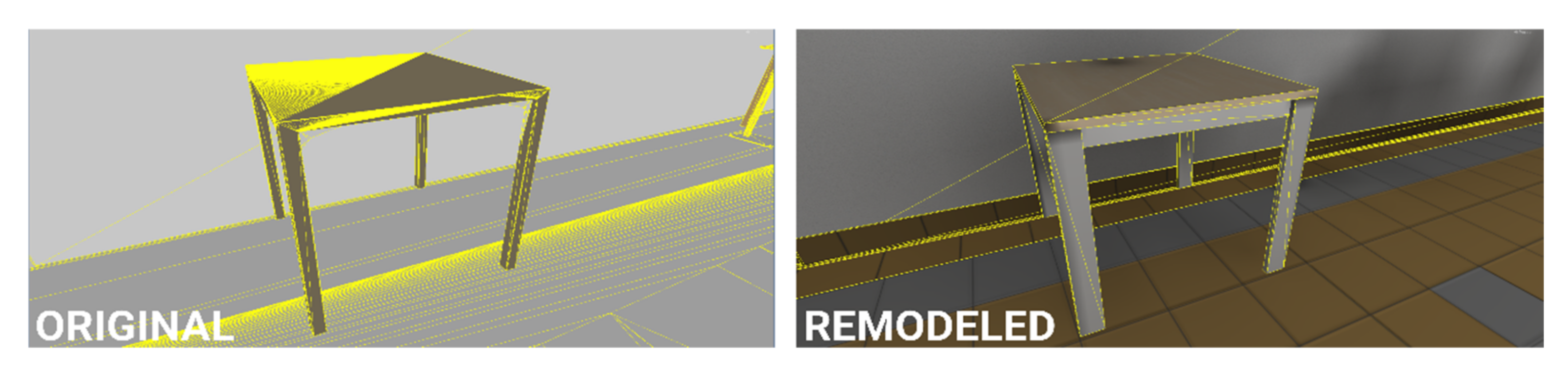
Many of the pre-existing objects and construction elements imported from the BIM model contained erroneous or somewhat complex geometry (consisting of too many polygons or individual parts). These had to be remodeled since they would cause performance issues in real-time 3D rendering (Figure 6). Other objects that were redundant in the final solution were discarded. Remodeling of unsuitable objects was performed either directly in Unity, using the ProBuilder extension [74] or externally, using the Blender modeling software [75]. ProBuilder’s integration with the Unity engine was useful in remodeling the building’s construction elements, whereas Blender was superior in maintaining good practices in creating 3D model topology (i.e., detailed objects). Some 3D models were created with two levels of detail (LoD) [76] to reduce the rendering load on the GPU. The result was a reasonable polycount (i.e., the total number of triangles present in the user viewport of the scene at any one time), which ensured stable performance with no visual frame drops (given the performance of the GPU). Frame drops would adversely affect the user’s overall perception of the scene. A high level of in-scene object detail (i.e., high polycount) also reaches a point of diminishing return (there is a significant difference in visual fidelity in observing a 3D model of a detailed object composed of a hundred polygons versus the same object composed of a thousand polygons; the visual difference between a thousand polygons and ten thousand polygons is nowhere as prominent, yet the increased rendering demands are much more significant).
Regarding the suitability of the final virtual scene for eye-tracking, the important components are not the models and 3D meshes themselves, but rather their physical collision (interaction) with the user’s gaze. These physical collisions between objects are mediated by colliders, which are invisible, simplified representations of the actual 3D models. Correct definition of such colliders is important for two reasons: (i) to register the user’s eye-tracking gaze (since colliders are the 3D equivalents of eye-tracking AoIs); (ii) to block the user from walking through objects that were not intended to be walked through (e.g., walls or furniture). Inspecting and testing the 3D scene at this point in development is crucial, because we want to ensure the virtual 3D scene retains the features of a controlled experiment with no unexpected issues. We check whether eye-tracking registers object colliders as intended, and that users can only move around within the bounds of a defined area while experiencing no walk-through glitches, fall-through glitches, or other, incorrect 3D geometry-related visual/interaction glitches (gaps or holes in 3D object models, flickering textures, objects defying reality by hanging in space or being unnaturally crammed together, etc.).
Implementing custom scripts into a virtual 3D scene (to provide user interactivity with objects and their surroundings, facilitate events, visuals, or animations, etc., between interactable actors in a scene) has its own challenges. While this paper focuses mainly on scripts related to eye-tracking, some comments about scripting in general should be offered.
Any 3D engine should have an analytics tool for logging and reporting the performance of a 3D scene, i.e., for both visual rendering and script execution. A badly written script that slows down the entire scene can therefore be discovered. In the case of Unity, analytics is provided through the Unity Profiler [77]. There are two kinds of scripts according to their execution time: on-event or loop-based. An on-event script is generally not a problem since the script is executed only once or sporadically (e.g., upon user-object collision). A loop-based script is executed frequently, up to once per every rendered frame. A heavy, poorly programmed script such as this can degrade the performance of the entire application. General script optimization recommendations [77] suggest (re)implementing as many scripts into the on-event category as possible and refraining from using execution-time heavy functions, such as hard drive read/write operations. While some scripts are execution-heavy by design (e.g., continuous user eye-tracking and other activity logging), there are still good and bad ways of implementing them. This is discussed in the next section. The overall performance budget of real-time rendering is always limited: if VR scene visualization and eye-tracking data renders and processes on a common VR device at 90 frames per second, it means we have a real time budget of 11 ms for each frame (1000 ms/90 = 11 ms). The scene geometry rendering and script processing must be performed below this time budget to ensure a smooth, continuous experience and valid data logging.
Because visuals, scripting implementations, and analytics are all combined, a standardized and automated performance test can verify the performance targets of the scene (as in software integration testing). To test the performance demands of a 3D scene, a user camera can be animated to fly through the scene. When the frame rate is logged during the fly-through, weak areas in the scene with frame rate drops can be discovered. The weak points can then be fixed by adjusting the 3D model polycount and then verified using the same camera fly-through. Standardized performance testing is achieved in this manner.
3.5. Data Acquisition and Related Algorithms
These implementations occur in experimental runtime and involve the capture of mainly raw eye-tracking data. While corrective eye-tracking measures can be employed (described in the following sections), it is economical to acquire the best possible measurements immediately from the experiment as opposed to correcting them later, provided the measurements can be corrected at that point.
An in-engine eye-tracking data acquisition script must execute continuously, producing a stream of dozens of entries per second. The frame rate for logging eye-tracking can be set according to either the VR headset display refresh rate or the sampling rate of the eye-tracker’s hardware. Logging eye-tracking in VR with a sampling rate that differs from the VR display refresh rate may need to be handled separately. In Unity, this is solved by the update and fixedUpdate functions. The update function executes scripts at the speed of the framerate (i.e., while visuals are rendered), and the fixedUpdate function can be used to process physics, engine program logic, and script extensions at a different rate [78]. With different display/eye-tracker frequencies, it is prudent to employ the fixedUpdate function. When this function is used, however, a new visual frame does not always render each time an eye-tracking measurement is taken (or vice versa). This is a minor problem for visual cognition, as these logging/rendering frequencies are sufficiently high to begin with [79]. Regardless, for the ease of the methodology, implementation, and data evaluation, it is preferable to use hardware in which the display/eye-tracker frequencies match and synchronize.
Implementation of user behavior logging is based on a generic logging script with public functions (i.e., functions accessible by any other script). This generic logging functionality can then be used by specific scripts, for example, eye-tracking logging scripts, user movement logging scripts, custom event logging scripts, etc. Once a VR application is launched, the generic logging script waits for other scripts to subscribe to it and specify their own logging formats, i.e., the VR eye-tracking logger calls the generic logger to create a dedicated CSV data file for the eye-tracking log output, along with specifying the log header (the variables). When the VR application is running, the subscribed scripts can pass their own data to the generic logging script whenever required. In the case of VR eye-tracking, this occurs at a pre-specified rate in the fixedUpdate loop. The generic logging script handles writing of the passed-on data into CSV files, along with implementing a writing cache for each of the subscribed loggers to reduce the overall demand on hard drive write performance.
This is the basis behind single-user logging. Implementations with multiple users in a scene (see Section 2.3, dynamic camera, dynamic scene variable level), may require an extra network layer to ensure correct logging functionality, i.e., the generic logging script must be implemented on a server, and all the user logging scripts of all involved users (separate devices—clients) must subscribe to the server. This ensures synchronization of all the user logs under a single, server-side time. A stable, low-latency and low packet loss local network is also a critical requirement, especially if eye-tracking is logged. For a related issue, refer to Section 3.7 discussing implementation challenges of a robust replay script.
For a solid, operationalized understanding of where a user’s eye-tracking gaze dwells in uncertain situations in real time during the experimental runtime, we propose two algorithmic workarounds: dual raycaster and multi-level collider segmentation.
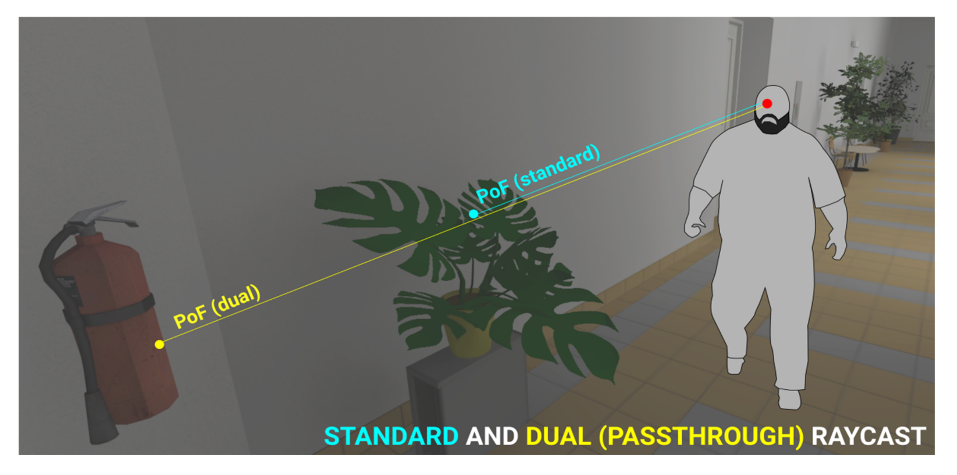
Dual raycaster—Regarding the fidelity of graphics in modern 3D rendering, an issue with transparent objects arises. Is the user looking at the transparent object or is the user looking through it and focusing on something more distant? In any 3D scene, this type of ambiguity in interpretation can arise in two forms: the object is either area-transparent, i.e., not convex, containing gaps/holes (e.g., plants, segmented mesh structures, etc.), or the object is surface-transparent, i.e., see-through texture (glass, liquids, etc.). While it can be difficult to nearly impossible to determine the actual object a user is looking at from a purely algorithmic decision (since the physical cue of eye accommodation present in perceiving near/far objects in the real world is non-existent in VR), it can at least be beneficial to log both cases of the ambiguity, i.e., simultaneously register both the transparent object and what is behind it (Figure 7). This is solved by assigning all transparent objects/colliders into a separate semi-pass-through object layer, followed by implementing a dual eye-tracking raycaster: one raycast is permitted to pass through the transparent layer while the other is not, and both are logged simultaneously.
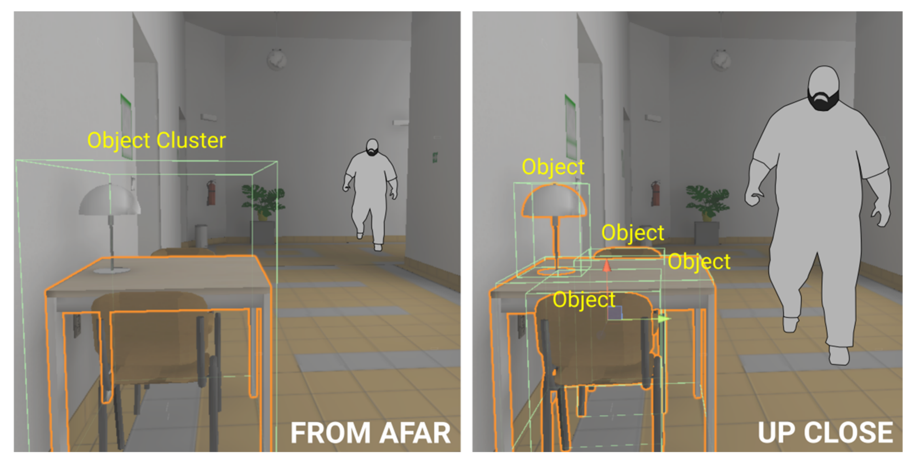
Multi-level collider segmentation—The interpretation of dwelling on distant objects can be challenging. The resolution of even the most advanced VR headsets of 2021 is noticeably less than the resolution provided by the fovea of the eye [23], and therefore distant and sufficiently small objects or a combination of these (i.e., objects of a low relative size) will be represented by just a few pixels when the virtual image is rendered. The issue may concern entire objects or only subsections of objects, provided the division of objects into segments is desired. A researcher interpreting such problematic data may ask whether they represent a valid eye-tracking gaze upon a relatively small object or just noise in the data. The inherent inaccuracy in all current eye-tracking technology also represents a problem in interpretation. A superior method of handling this is operationalization, i.e., defining the distances from which an object is relevant as a potential gaze target. At a global level, this can be defined by a maximum permitted eye-tracking raycast distance (calculated as the distance of a straight line from the user’s virtual camera position to the potential point of fixation on a 3D object). The global maximum raycast distance does not, however, take into account relative object size. Any 3D object in a scene relevant to eye-tracking can therefore be segmented according to a custom-distance multi-level collider distinction; for example, non-registered distance (sufficiently far-away to be disregarded by the eye-tracker), standard distance (standard eye-tracking collider (AoI) registration), detailed distance(s) (sufficiently close for the single object collider to be broken into segmented parts). Established in this manner according to each relevant object of interest in the scene, the setup checks for user-object distance, and upon crossing a threshold distance, the colliders assigned to the object are interchanged or enabled/disabled (Figure 8). This can be implemented in two ways: the simple implementation works with predefined threshold distances (specified manually for each object), whereas the advanced implementation uses algorithmic detection of relative object size, as seen by the user, to set/disable object colliders dynamically.
A specialized collider adjustment scenario arises when objects of significance are tracked in a scene where the surrounding objects can be disregarded. In this type of scenario, the collider can be enlarged or shrunk continuously and linearly (as opposed to the aforementioned discrete collider level transitions) to adjust to the user distance and eye-tracker accuracy threshold. This, however, is a computationally intensive operation, one that should be used only for a select few objects, if at all.
Both the dual raycaster and multi-level collider algorithms require some manual input and testing from the researcher before application in a 3D eye-tracking experimental scene. The algorithms can, however, contribute to more intelligible data output. A hybrid of the two algorithms can also be implemented, incorporating a dual raycaster solution in which objects of a virtual environment are tracked in higher/lower detail/segmentation simultaneously. This approach can offer multiple levels of interpretation.
3.6. Data Cleaning, Curation, and Related Algorithms
The data obtained in experimental runtime may contain some inaccuracies introduced either by user physiology (brief sudden eye-movements and data loss caused by blinking, or miscalibration) or the eye-tracker (inaccuracy). Some of these inaccuracies can be corrected, while some should be discarded. The algorithms proposed for this purpose adopt two possible data curation paths: (i) clean the data and send them to an external application for statistical processing; (ii) clean/correct the data and reload them into the 3D engine for more processing or visualization (i.e., evaluation runtime).
Some eye-tracker APIs inherently report data loss, i.e., moments when no eye-tracking pupil or corneal signal could be registered. If reported by the API, it is best to implement this into the logger so that the data loss value (Boolean true/false) is included in the log. If data loss is already present, the data cleaning process may simply erase the data entries flagged for data loss. If, however, no data loss is present in the log (whether due to a missing implementation or API feature), data loss events can be recomputed using an external data processing script. A data loss event may manifest as the eye-tracking raycast angle not moving relative to the user camera rotation. In this case, detection and removal of the data loss is accomplished by computing the difference between the user’s camera angle and the user’s eye-tracking raycast angle. If the difference remains static across a time period (i.e., subsequent logs), this can be considered data loss and removed.
A similar data cleaning procedure entails identifying eye-tracking artifacts (eye saccade movements so unnatural that they would be physically impossible to perform), for example, a measurement error caused by blinking, in which the eye-tracker measures an incorrect eye-position while the eyelid is partially closed and in motion and where the assumed eye coordinate is projected into a radically different direction in a very short period of time (this would be physiologically impossible). Such incorrectly measured data can be erased simply by computing the differences in angles between subsequent logs and removing the instances that contain large, outlier numbers.
These types of correction are rather primitive since they rely on deleting incorrect data. However, corrective approaches can also be considered and implemented by repairing, interpolating, or reinterpreting data. This is often feasible, as one of the advantages of eye-tracking in VR is that the virtual world is geometrically defined and therefore fully measurable and computable using linear algebra [80].
Recaster loads an existing eye-tracking log acquired in experimental runtime into the 3D engine and once again raycasts the data onto the environment, i.e., by accessing each subsequent eye-tracking log entry, user camera position (raycast origin) and raycast angle to reproduce each raycast hit or point of fixation. This is useful when the naming convention or atomicity of the objects in the scene is redefined after data collection, for example, to obtain more accurate data resolution or for corrective reasons. Recasting the raycast does not alter the time, user position, head rotation, or eye-tracking gaze angle data in the eye-tracking log, only the information concerning the raycast-hit object’s name. Coordinate and distance may also be overwritten if objects or colliders in a scene are altered. However, it must be emphasized that while redefining invisible object colliders or their names seems logical, the act of significantly rearranging the visual layout of the 3D models that constitute the scene would be scientifically incorrect, producing either skewed data, or representing a process similar to statistical data tampering.
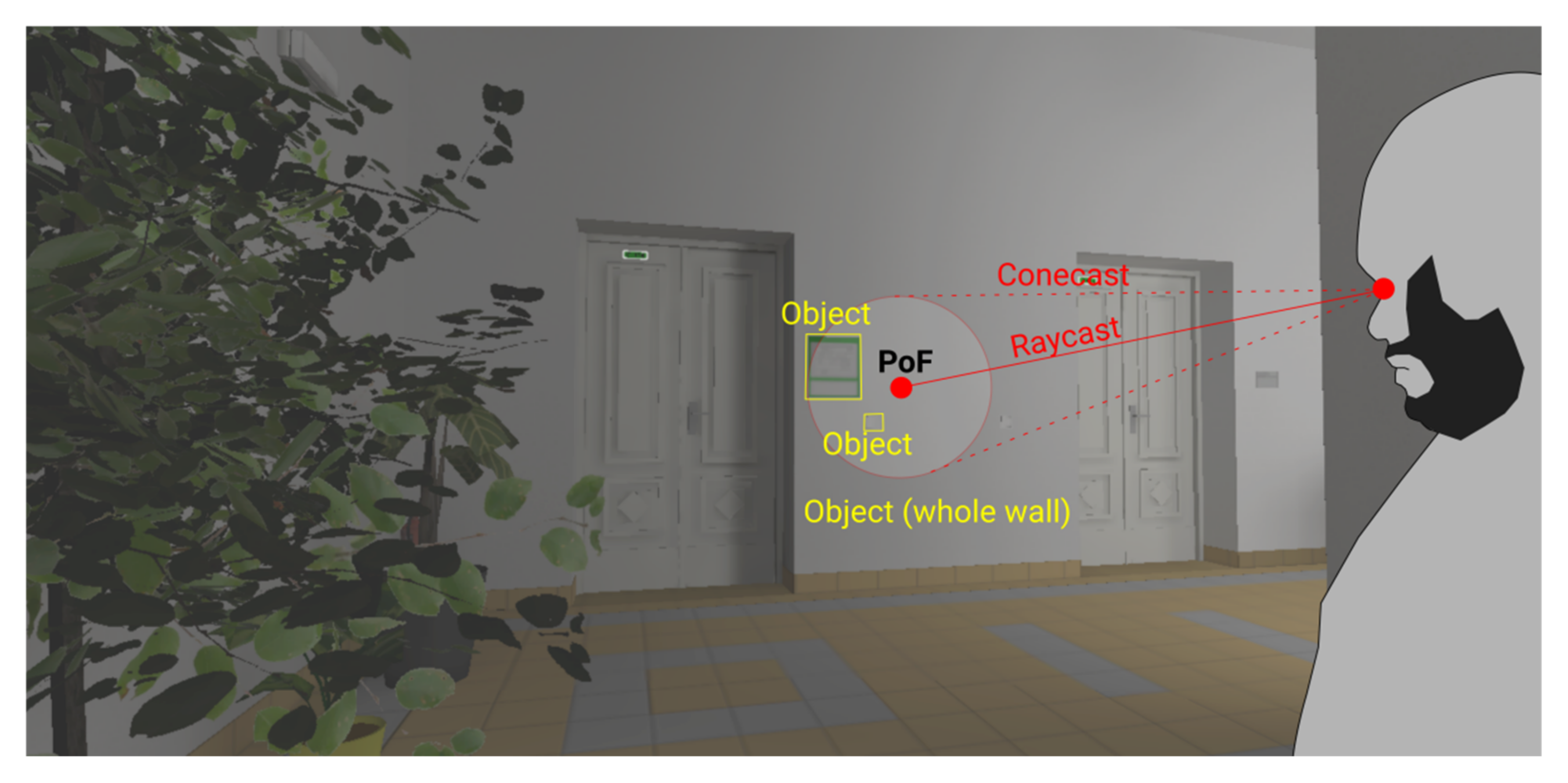
Eye-tracking magnetism is an implementation for correcting eye-tracker inaccuracies based on machine-estimation of the importance of objects in the focal area. It takes into account a predefined level of potential inaccuracy, depending on the hardware and user eyesight (often a circular spread of five to ten degrees is considered a potential focal area [81]). Then, instead of only a raycast, the algorithm considers a conecast (a conical projection with a diameter equivalent to the specified range). On initialization, the script loads user data that have already been collected, as with the recaster implementation, but now the raycast angle is the central point of the conecast. The algorithm then considers all the objects captured within the cone’s diameter (Figure 9). Depending on the setup and the algorithm, the magnetism feature can estimate and attempt to correct what the user is looking at. The magnetism principle specifies that if a user’s gaze dwells on an insignificant area near a significant object, the algorithm will snap-correct the gaze onto the important object. However, what determines an object’s importance is a matter of context and manual setting-up. For example, if the conecast catches the user gazing at a bland-looking white wall with a sufficiently nearby contextual object of importance (e.g., a navigation sign), the algorithm will assume this is a measurement error and snap-correct the gaze onto the object of importance. The object, however, must be manually pre-set as important (or a complex prediction algorithm capable of spontaneously determining the object’s importance can be employed).
Nevertheless, correcting the user’s gaze onto a single important object in close vicinity is a simple example. The eye-tracking magnetism evaluation process becomes more complicated as multiple objects of importance are captured within the conecast. When this occurs, the question arises as to what type of heuristic the algorithm should employ. Does it consider the object whose prominence is closest to the cone’s center? Does it consider the object with the highest percentage of its volume within the conecast? Does it consider the object with the highest significance rating (as defined by the object’s shape and texture, relative to its surroundings)? Or does it consider a combination of all these factors, and if so, what significance do individual factors play in this combination? As seen from this line of thought, the conecast algorithm is only a proof-of-concept at this point, with full implementation depending on other algorithms or heuristic processing.
3.7. Data Visualization and Related Algorithms
Reimporting CSV data logs into a 3D engine for visualization purposes can be achieved by programming language data structures that efficiently load and work with database-like logs (e.g., List, Dictionary, and HashTable). A challenge is the amount of data that are loaded and the engine’s capacity to process and visualize these data. A 3D engine is ill-equipped to deal with thousands of atomic log entries, each represented as a single coordinate object, a point of fixation (as acquired according to the eye-tracker’s logging rate). Additionally, visualizing raw data brings about less clairvoyant interpretative value compared to the value processed data offers. Some analytics may therefore require pre-computing the raw CSV data by using external or in-engine scripts (which apply spatial computations).
Regardless, processing the data in evaluation runtime implies that some evaluation slowdowns are acceptable (since a substantial loss in framerate or an algorithm-induced lag due to instantiating and handling thousands of small objects is a likelihood). It is therefore acceptable to first instantiate all the data log entries in the engine, process them while considering the existing 3D geometry, and cut out and simplify them afterwards, provided sufficient computer memory is available to manage all the log entries and computations.
Before algorithmic data processing commences, another method of comparing the data is useful, for example, manual verification facilitated by dynamic replay functionality. For this purpose, a replay script can be implemented. This contains two perspectives for consideration: the programmer’s perspective (i.e., the format of the input data, and what the script can do with such data), and the user’s perspective (i.e., the user interface, presentation of the data in a comprehensible manner, researcher control, and convenience of the data and related visualizations, and the utility of this).
Given the list of minimum content required in eye-tracking data logs (Section 3.3), a data source such as this is sufficient. The replay script should, however, be designed and implemented so that different data logs (if produced by different eye-tracking logging scripts) can be loaded, i.e., the replay script should not rely on hard-coded, unspecifiable naming of variables. Ideally, it should also include algorithms for recomputing a missing variable from an included variable, in which the former can be derived from the latter.
In the user interface, the basic implementation is a temporal one: the replay script takes control of the user’s camera and uses the loaded CSV positional and rotational data to replay the user’s movements, and gazes exactly as the user moved about in the experimental environment. Visualization of the eye-tracking data can also be added to the replay. The eye-tracking coordinate is visualized as a small object (e.g., a sphere) and rendered at the point of fixation coordinates that were acquired at a specific time, according to the existing CSV log entries.
Beyond the basics, the replay script’s functionality and presented visual information can also be extended. To glimpse the cognitive processes behind the user who is observing the environment, a trailing fade-out of the last few previous eye-tracking coordinates can be rendered. The replay functionality can be slowed down, accelerated, rewound, or paused. To control this feature, basic GUI (graphics user interface) or keyboard shortcuts can be implemented. The GUI can also display a spontaneous overview of eye-tracking information, which includes the name of the currently fixated object, the amount of time spent dwelling on the currently fixated object, etc.
A robust replay script can also visualize multiple inputs from various perspectives, i.e., if data are collected during a multi-user (multiplayer) experiment, multiple sources of simultaneous user behavior will be available. Similarly, interactable or autonomous objects present in the virtual scene would need data logs of their own, as they may move about, change their properties or states, or be acted upon by a user. If such an enormous amount of interaction occurs in the experimental scene, replay functionality implemented by manipulating a single user’s camera would not suffice. It would then be necessary to supplement the replay GUI/shortcuts with another, free-to-move observer camera that the researcher can use to observe multiple users/objects from their own perspective or projection. Such a robust multi-actor replay script, however, is beyond the scope of this paper, but having such a utility developed and available would lead to further advancements in the research capability of VR interaction.
Eye-tracking data can be rendered as a static visualization. Upon loading a CSV eye-tracking data file into the 3D engine, the data are then portrayed in the scene. It can be portrayed either fully (raw, unprocessed data), or further processed by an external script or an in-engine eye-tracking aggregation algorithm. Other related eye-tracking data (e.g., user movement, interaction) can also be visualized.
When the individual log entries are loaded and instantiated into the 3D engine as 3D objects, it is good practice to attach a data container to each object. While a data container merely copies or recomputes the data in the CSV log entry from which the 3D object is created (e.g., log id, log time, and raycast distance), this procedure serves optimization purposes. Instead of searching the log table data structure for each 3D computation of the log-originated 3D objects, the data can now be accessed directly from each individual 3D object according to its spatial dimension. This also aids in linking the instantiated eye-tracking objects with other instantiated objects (e.g., eye-tracking coordinates to movement coordinates).
Another key aspect of processing static eye-tracking data is optimization of the algorithm. A comparison of the entire data set of coordinates, entry-to-entry, constitutes an exponentially growing computational difficulty (factorial). Some demanding algorithms may therefore encounter a limit in available memory or in the sheer computational time required for processing. Implementing spatial algorithm optimizations, such as spatial partitioning [82], or at least a basic form of data prefiltering to disregard the irrelevant entries, is recommended.
Heatmap algorithms (absolute distance) are a basic form of visualizing spatial attention. While the interpretative value of this method is already limited in traditional eye-tracking due to a lack of the temporal factor [83], the situation is worse with 3D eye-tracking, especially with differentiating depth in a highly varied 3D environment. The standard heatmap algorithm considers the absolute distance of all the eye-tracking point of fixation coordinates and determines how closely they are lumped together. Differences in spatial depth, however, introduce differences in absolute point-to-point distances. The standard heatmap algorithm is therefore not suitable since it must be corrected for relative distance and (optionally) also the temporal factor. We mention this algorithm because it serves as the basis for all other static visualization algorithms in eye-tracking. The algorithm checks for the distances of other points and how close they are to the point of fixation currently being processed. Based on the number or proximity of neighboring points deemed close enough to the current point, the current point is assigned a heatmap index value. Then, as all the individual points are processed, they are colored with a color gradient according to their assigned values (e.g., gray/invisible = below the threshold of consideration; light gray = minimum amount of gaze concentration; red = maximum amount of gaze concentration).
The heatmap visualization can take the form of colored geometric primitives (e.g., a small sphere for each point of fixation, as depicted in Figure 10), which is a simple, albeit crude implementation. A more challenging implementation entails visualizing the heatmap as an overlay texture or as a custom graphics shader (i.e., decal system or decal shader [84]). This, however, requires a complex and constrained implementation, because most 3D scenes are composed of multiple objects that contain multiple overlapping textures, some of which use complex texture shaders (the object heatmap overlay is a shader that can interfere with other shaders). Since designing a 3D scene for use with a heatmap overlay texture requires adapting the scene creation process to the heatmap’s constraints and involves increasing implementation costs, the present paper disregards the use of overlay heatmap textures.
Corrected heatmap algorithms (relative distance) are more suitable for obtaining spatial information in VR eye-tracking data with user movement in the virtual space. This is a valid correction in which point-to-point distances are determined according to an observed angular distance rather than an absolute metric distance.
Interpreting absolute point-to-point distances projected onto varying spatial depth in a non-corrected heatmap algorithm can be alleviated, to an extent, by a simple implementation of cut-out distances. Computing an absolute-distance, uncorrected heatmap while including only the points of fixation that were observed within a specified distance interval will discard the remainder of the points from processing and visualization. While this procedure is simple, it does not solve the root cause of the problem—the need to interpret sequences of PoF data with a high variety of absolute distances (e.g., just like looking down the corridor in Figure 10). Thus, environments with high spatial variance (or with user-induced movement causing such variance) are not fit to be interpreted by the uncorrected (absolute distance) algorithm.
The corrected heatmap works well for all distances since it uses conecast. Cone projection from the user’s position covers the eye-tracking point of fixation coordinate and its surroundings. The angular width of this conecast can be specified according to the algorithm’s parameters. Only the surrounding points captured within the cone are then considered for the corrected heatmap computation (this also helps tremendously with the issue of optimizing the otherwise exponentially rising difficulty for the algorithm, where each point would require measurement of its distance from all the other points). However, because the points are compared to each other in relative distances, it implies that the difference in user movement will lead to different results. For example, comparing points A–B may determine that they are within a sufficiently close distance, whereas comparing points B–A may yield the opposite, especially when the gaze produced to generate log entry B was taken from a shorter distance, where the cone’s angular distance would not protrude sufficiently far from point B to include point A. Another issue is that of occlusion, in which a varying camera angle/position conecast may not register some points previously looked at. Hence, this may introduce variation in the heatmap’s visualization intensity/coloring, which can be either kept as is, or the algorithm can be expanded to smoothen such A–B/B–A differences.
Corrected fixation algorithms (relative distance–time) are an extension of the previous algorithm, with the ability to compute eye-tracking fixations in virtual 3D space. The angular distances between subsequent points can effectively distinguish between eye-tracking fixations and saccades; the minimum or maximum duration of a fixation can be set and visualized (the algorithm is now a sequential pass-through on the eye-tracking data log). Similar algorithm (including discussing suitable time and angle thresholds) is proposed and experimentally verified by an existing study [85].
Depicting eye-tracking fixations, saccades, and scan paths is also a visualization issue. The output visualization can produce many fixations that overlay each other, as a user may observe a virtual 3D object of interest from many different angles and distances (we can argue that not only do 3D visual stimuli offer more information than their 2D counterparts [86], they also require more cognitive processing [87], i.e., dwell time). It is also relevant that the user moves about in the 3D environment. Subsequently, the following must be visualized: eye-tracking scan path with fixations, user movement path, and associated eye positions at any given time. While this is easily implementable in a 3D engine (using a series of geometric primitives to depict the points of fixation and basic geometric lines (e.g., Unity’s LineRenderer class) to connect the subsequent points into a path), the comprehensibility of the resulting visualization may be worth further consideration, filtering, or simplification, etc., especially for cases of prolonged interaction or multi-user visualizations.
4. Discussion and Conclusions
The paper discussed the processes and challenges of eye-tracking in spatially complex or interactive VR environments with high degrees of user freedom. The paper explored and applied these challenges at a theoretical level to define a desired level of interpretation in eye-tracking for the design and production of virtual environments that adhere to this level, to clarify the data processing requirements and partially automate data processing, and to explore methods for applying corrective actions to the acquired data (facilitated by the proposed algorithms).
4.1. Contributions to Eye-Tracking in VR
The paper provided an overview of working with eye-tracking data for experiments or applied scenarios built around the theory and proposed algorithms—all the processes and data flow related to eye-tracking in virtual environments are proposed to be regarded as a software architecture and a structured approach (Section 3.2, Figure 3). Specifics of designing and building 3D virtual environments optimized for eye-tracking research are covered (Section 3.4). During data collection, a raw eye-tracking data stream (Section 3.3) is projected against the virtual environment and saved into a CSV file (Section 3.5). The raw data are then processed through an external script and cleaned of noise. The data can then be further processed externally to obtain basic statistical metrics, or the data can be imported back into the 3D engine for the 3D/in-engine algorithms to execute spatial corrective processing (Section 3.6). The reloaded or reprocessed data can be visualized and interpreted in-engine, over the experimental environment (Section 3.7).
Given the breadth of the subject, the paper is not exhaustive. Future research will address the paper’s shortcomings and extend its potential—mainly by extending the provided algorithm examples into polished solutions that are applicable in experimental settings and verifiable for their algorithm and interpretation efficacy. While the linked GitHub repository is documented in both its readme file and source code comments, future work predetermines the repository to become a living text with updates and additions. Regardless, the GitHub algorithm source code examples published along with this paper will serve as a basis for future implementations. The algorithms were implemented as complements to the algorithm proposals described in Section 3.5, Section 3.6 and Section 3.7. The included algorithms are listed and described as follows:
- experiment\PathScript.cs is our custom-built logger. On its own, it implements generic logging functionality (i.e., user movement, user interface usage, and user collision with other objects (e.g., spatial polygons depicted in Figure 5)). Moreover, custom logs to be passed to it, to be written into CSV files. Eye-tracking data can be one of such custom inputs.
- experiment\DualRaycaster.cs is an extended implementation of the raycaster function provided by the SRanipal API [62]. The second raycaster can be specified to pass through some virtual environment object layer(s) (Section 3.5, Dual Raycaster). It utilizes the PathScript logger to produce eye-tracking CSV logs. The logged variables are derived from the variable listing needed for further eye-tracking data processing (Section 3.3).
- experiment\MultiLevelColliderClient.cs and experiment\MultiLevelColliderServer.cs is a server-client solution for segmenting eye-tracking colliders (AoI) according to the user-object distance (Section 3.5, Multi-level collider segmentation). The server-client separation is intended so that the collider switching logic can be customized regardless of the collider-switchable objects present in a 3D scene—meaning that multiple clients subscribe to one server. Depending on server implementation and set-up (performance and evaluation heuristics), multi-level eye-tracking colliders are switched through the experimental runtime.
- verification\CSVReader.cs is an auxiliary script that loads CSV files back into the evaluation runtime (Section 3.2), to be converted into a List<Dictionary<>> data structure. Such data structures can be processed further by data cleaning (Section 3.6) and data visualization (Section 3.7) algorithms.
- verification\Recaster.cs is a re-raycasting script intended to reprocess existing eye-tracking data onto a scene with post-hoc altered 3D object and 3D object collider naming/structuring (Section 3.6, Recaster). The script utilizes CSVReader to load existing data; the 3D coordinates (user positional, user camera rotation, and eye-tracking angle) are used to re-raycast eye-tracking gaze onto the altered virtual environment, and the acquired results are saved, again, using PathScript.
- verification\et_recalculation.pde is an external script written in Processing programming language. The script processes eye-tracking CSV files produced by the raycaster/logger, to filter out junk data, data loss, and gaze segments too brief to be considered fixations. The provided verification\et_recalculation_sample\ directory also contains example input data and their reprocessed counterparts.
- visualization\ReplayScript.cs provides replays on acquired user behavior data including eye-tracking data, if existent (Section 3.7, Replay script). As the script loads a user’s CSV log using CSVReader, it takes control of the evaluation runtime camera to move and rotate through the virtual scene in real-time in a same way as the user (as specified by the positional and rotational vectors included in the CSV file). Eye-tracking data can be visualized, e.g., as a small white sphere rendered at the PoF positional vector, as hit by the eye-tracking raycast back in the experimental runtime.
- visualization\HeatmapVisualizer.cs and visualization\PathVisualizer.cs are two examples of visualizing existing CSV data (Section 3.7, Heatmap algorithms). PathVisualizer uses Unity LineRenderer class to show user movement trajectory through the virtual environment. HeatmapVisualizer processes eye-tracking data (Figure 10). Given the computational difficulty of processing large quantities of eye-tracking data, the example HeatmapVisualizer already contains some optimizations: a setting to process only interval subsets of eye-tracking data, and another setting to process only area subsets of eye-tracking data (the area can be defined by assigning a spatial polygon).
DualRaycaster.cs is an extension of an existing raycasting script included in the SRanipal API [62]. CSVReader.cs is a generic data file processing script adopted from an external source [88]. Original authors of both scripts are mentioned in their respective source codes. All other source code is a work of our own. As for algorithms that were merely proposed in the paper and not implemented (due to their complexity and the need for further work), this concerns Section 3.6, Eye-tracking magnetism, Section 3.7, Corrected heatmap algorithms, and Section 3.7, Corrected fixation algorithms.
The main point this paper drives is that while virtual 3D environments prove to be a challenge in collecting and evaluating eye-tracking data using existing conventional 2D eye-tracking methodics (especially if said 3D environments are highly spatially and structurally complex, dynamic, and interactive), virtual 3D environments also are explicitly defined in their 3D vectors and structures. As such, virtual 3D environments are mathematically computable, and a good-enough spatial algorithm should then be able to make sense of the complications arising from introducing the third dimension into eye-tracking. Therein lies the utility of the provided and proposed algorithms. This is not to say that the existing body of knowledge in traditional 2D eye-tracking (or mobile eye-tracking, for that matter) is of no use here—it is, in cases where spatial 3D computations are not relevant (e.g., when dealing with PoR or aggregated data). When filtering out junk data from the eye-tracking stream or working with eye-tracking colliders (AoIs), existing 2D methodics [89] can be used. However, when data are interpreted at 3D projection heatmap/fixation level (PoF), the computations have to be executed in a 3D-specific way.
Throughout the paper, data structures are mentioned (from CSV files to Lists and HashTables), to carry eye-tracking data in and out of a 3D engine. Computer graphics raytracing [90] classes (Raycast and Conecast) are used as part of the available API. 3D engine-specific components like Layers or Colliders are utilized. All this is nothing new in graphics programming. However, the value added by this paper lies in the ingenuity of combining these classes to obtain viable 3D eye-tracking concepts or working solutions per methodological arguments laid out in Section 1 and Section 2.
4.2. Future Prospects
The provided example algorithms leave room for improvement—to be expanded further to alleviate some of the issues of eye-tracking in 3D space (per Section 2.3). Some other related issues (e.g., visual evaluation and operationalization of space, 4D visualization in 3D space, and external application use) are merely glanced over in the paper. This concluding section is to elaborate on both the subsets of issues.
Evaluating virtual scene visuals can be achieved algorithmically, to prepare and optimize a scene for experimental purposes (Section 3.5). If spatial and visual properties (e.g., visual saliency, scene variety/complexity, or view distance) can be evaluated by image processing and spatial computation algorithms [91] prior to, or in addition to, user eye-tracking feedback, this can validate virtual experimental conditions. There is the problem of specifying fitting eye-tracking object colliders (AoI); since 3D objects acquired by means like photogrammetry [32,92] or procedural 3D asset generation do not have clearly defined AoI separations, segmenting objects into eye-tracking colliders is an open question. In static 2D imagery, saliency algorithms can be used for machine AoI detection [93,94]. If such algorithms can be used with 3D environments (e.g., by averaging multiple pictures taken from multiple virtual positions/angles), 3D AoI segmentation can be achieved.
Beyond mere passive logging of gazed-upon coordinates, eye-tracking can also be used to trigger interactive elements in virtual scenes. Compared to passive eye-tracking logging, eye-tracking user-controllable interfaces can leave feedback for the user in visual or auditory cues, interface-changing rules, etc. This can range from very simplistic solutions, such as an object lighting up when it is gazed upon, to complex, composite interactions of multiple interfaces or in-scene actors. Such interactions, by their own design, make the scene a dynamic one, thereby increasing the complexity of evaluating user behavior around them (described in Section 2.3). While interactive eye-tracking applications involve user experience and cognitive processing of interactive tasks, which is beyond the scope of the present paper, it is worth emphasizing that eye-tracking need not always be used merely for passive data-acquisition, and that the technology can be tailored to fit interactive needs [95] and scenarios [96].
Presenting multi-dimensional data, or a large quantity of data, is a computer visualization/design challenge [97]. Eye-tracking in VR may demand either four-dimensional or five-dimensional visualizations (i.e., a three-dimensional visualization extended with factor(s) for user/object movement in time and user/object state/property changes). When user camera(s), user-to-user interaction, user-to-object interaction, or object placement/properties change through time, the number of variables and values that require tracking expands and must be managed with operationalization, implementation, logging, rendering, and replaying. The included replay script is only a simple prototype solution with a basic visualization feature. Similarly, the provided heatmap visualization script can become an illegible depiction, should long-enough eye-tracking logs of complex-enough spaces be processed. Existing studies [38] or solutions [31] have also not addressed this issue; the complexity of the issue may need to be solved through software suites with GUI and layered approach to viewing, filtering, and processing different kinds or segments of data. Thus, proposing a classification system of virtual environment behavioral data may be needed; similarly, implementing VR user interfaces to work with viewing and processing these data may also be of value.
Processing and visualizing all the user behavior data in a 3D engine may seem clumsy and computationally intensive on resources, but existing external visualization applications may be considered in balance, with both advantages and disadvantages. The utility of a 3D engine lies in its accessibility to programming language and the API used in the experiment, to the point of accessing object behavior and object components related to that experiment. However, spatial data algorithms such as movement heatmaps or path averages are not implemented in a 3D engine by default. Instead of reimplementing them, they can be visualized by external GIS software [98] (which, in turn, only accepts a graphically and functionally simplified version of an experimental scene).
On a general note, VR scenarios offer high interpretative value, provided the constraints of the platform are taken into account in preparing an experiment and implementing an environment. The implementation and evaluation difficulty of dynamic scenes with many degrees of freedom of movement is balanced by the inherent advantage of VR as a medium, i.e., by its ability to present complex stimuli while maintaining (some) experimental control over the scene and isolating users from the types of unwanted, disruptive, and intervening variables that tend to plague real-world scenarios. As mentioned in a previous overview study [37], experiments in eye-tracking in VR have both advantages and disadvantages compared to traditional eye-tracking research. These manifest at the level of experimental stimuli, experimental tasks, and measured behavior. Freedom in user movement and action can facilitate the emergence of individual differences in cognitive processing of scenes, interaction with objects, user controller use, and their overarching strategies [99,100]. Applied experimental settings of different types, which implement various, often customized user controllers, can make use of this in simulators for engineering [101], military [102], medical purposes [103], experimental cartography [104], collective learning [105], etc. Furthermore, the principles and the algorithms of eye-tracking in VR can be used in the aforementioned fields to add to the interpretation value of the overall acquired data.
In closing, any implemented corrective eye-tracking and related algorithms must be considered critically. If they are employed for interpreting complex environments, a key question is the extent of such corrections. Is there such a thing as an experimental eye-tracking scene so complex that it is not worth interpreting? And where exactly does that threshold lie? Future research can take this direction and verify the efficiency of corrective eye-tracking algorithms, and possibly also provide newer, improved versions, pushing the efficiency of the corrective solutions further. In parallel, eye-tracking in VR environments re-created from their real counterparts can be compared with eye-tracking in the original (i.e., by comparing eye-tracking in VR with mobile eye-tracking [106] or 2D eye-tracking studies [107]), to test for the ecological validity of the virtual method and visualization.
Author Contributions
Conceptualization, Z.J., S.T. and P.U.; methodology, S.T., P.U. and Z.J.; software, P.U. and O.K.; data curation, P.U.; writing—original draft preparation, P.U. and O.K.; writing—review and editing, Z.J. and S.T.; visualization, P.U. and O.K.; supervision, Č.Š. and S.T.; funding acquisition, Č.Š. All authors have read and agreed to the published version of the manuscript.
Funding
This research was funded by a grant from the Technology Agency of the Czech Republic No. TL02000103 called “Cognitive psychology and space syntax in virtual environments for agent modeling”, and Pavel Ugwitz was also supported by a grant of the Masaryk University No. MUNI/A/1576/2018 called “Complex research of the geographical environment of the planet Earth”.
Institutional Review Board Statement
Not applicable.
Informed Consent Statement
Not applicable.
Data Availability Statement
Not applicable.
Acknowledgments
This work was supported by the research infrastructure HUME Lab Experimental Humanities Laboratory, Faculty of Arts, Masaryk University. Our thanks also go to proof readers and reviewers.
Conflicts of Interest
The authors declare no conflict of interest.
References
- Gliner, J.A.; Morgan, G.A.; Leech, N.L. Research Methods in Applied Settings: An Integrated Approach to Design and Analysis; Routledge: London, UK, 2017. [Google Scholar]
- Strube, M.J. Psychometric principles: From physiological data to psychological constructs. In Principles of Psychophysiology: Physical, Social, and Inferential Elements; Cacioppo, J.T., Tassinary, L.G., Eds.; Cambridge University Press: Cambridge, UK, 1990; pp. 34–57. [Google Scholar]
- Rayner, K. The 35th Sir Frederick Bartlett Lecture: Eye Movements and Attention in Reading, Scene Perception, and Visual Search. Q. J. Exp. Psychol. 2009, 62, 1457–1506. [Google Scholar] [CrossRef] [PubMed]
- Hooft, E.A.J.V.; Born, M.P. Intentional response distortion on personality tests: Using eye-tracking to understand response processes when faking. J. Appl. Psychol. 2012, 97, 301–316. [Google Scholar] [CrossRef] [PubMed]
- Tsianos, N.; Germanakos, P.; Lekkas, Z.; Mourlas, C.; Samaras, G. Eye-tracking users’ behavior in relation to cognitive style with inane-learning environment. In Proceedings of the Ninth IEEE International Conference on Advanced Learning Technologies, Riga, Latvia, 15–17 July 2009. [Google Scholar] [CrossRef]
- Sasson, N.J.; Elison, J.T. Eye tracking young children with autism. J. Vis. Exp. 2012, 61, 3675. [Google Scholar] [CrossRef] [PubMed] [Green Version]
- Coetzee, R.; Regel, S. Eye movement desensitisation and reprocessing: An update. Adv. Psychiatr. Treat. 2015, 11, 347–354. [Google Scholar] [CrossRef]
- Ekman, P. Emotion in the Human Face; Malor Books: San Jose, CA, USA, 2015. [Google Scholar]
- Changing Minds. Eyes: Body Language. 2012. Available online: http://changingminds.org/techniques/body/parts_body_language/eyes_body_language.htm (accessed on 31 July 2021).
- Yarbus, A.L. Eye Movements and Vision; Plenum Press: New York, NY, USA, 1967. [Google Scholar]
- Falck-Ytter, T. Gaze performance during face-to-face communication: A live eye tracking study of typical children and children with autism. Res. Autism Spectr. Disord. 2015, 17, 78–85. [Google Scholar] [CrossRef]
- Sharma, K.; Giannakos, M.; Dillenbourg, P. Eye-tracking and artificial intelligence to enhance motivation and learning. Smart Learn. Environ. 2020, 7, 1–19. [Google Scholar] [CrossRef]
- Shipman, K. MetaHumans—A look past the Hype. Puget Systems. 2021. Available online: https://www.pugetsystems.com/labs/articles/MetaHumans---a-look-past-the-Hype-2139 (accessed on 31 July 2021).
- Buswell, G.T. How People Look at Pictures: A Study of the Psychology and Perception in Art; University of Chicago Press: Chicago, IL, USA, 1935. [Google Scholar]
- Wade, N.J. Pioneers of eye movement research. i-Perception 2010, 1, 33–68. [Google Scholar] [CrossRef] [Green Version]
- Cornsweet, T.N.; Crane, H.D. Accurate Two-Dimensional Eye Tracker Using First and Fourth Purkinje Images. J. Opt. Soc. Am. 1973, 63, 921–928. [Google Scholar] [CrossRef]
- Charlier, J.; Hache, J. New instrument for monitoring eye fixation and pupil size during the visual field examination. Med. Biol. Eng. Comput. 1982, 20, 23–28. [Google Scholar] [CrossRef]
- Van de Kerkhof, M.; Benschop, J.; Banine, V. Lithography for now and the future. Solid-State Electron. 2019, 155, 20–26. [Google Scholar] [CrossRef]
- Safin, R.; Garipova, E.; Lavrenov, R.; Li, H.; Svinin, M.; Magid, E. Hardware and software video encoding comparison. In Proceedings of the 59th Annual Conference of the Society of Instrument and Control Engineers of Japan (SICE), Chiang Mai, Thailand, 23–26 September 2020; pp. 924–929. [Google Scholar] [CrossRef]
- Cognolato, M.; Atzori, M.; Müller, H. Head-Mounted Eye Gaze Tracking Devices: An Overview of Modern Devices and Recent Advances. J. Rehabil. Assist. Technol. Eng. 2018, 5, 1–13. [Google Scholar] [CrossRef] [PubMed]
- Ewalt, D.M. Defying Reality: The inside Story of the Virtual Reality Revolution; Blue Rider Press: New York, NY, USA, 2018. [Google Scholar]
- Levy, R.M. The virtual reality revolution: The vision and the reality. In Virtual Reality—Human Computer Interaction; Xinxign, T., Ed.; InTech: Šid, Croatia, 2012; pp. 21–36. [Google Scholar]
- Zhan, T.; Yin, K.; Xiong, J.; He, Z.; Wu, S.-T. Augmented Reality and Virtual Reality Displays: Perspectives and Challenges. iScience 2020, 23, 101397. [Google Scholar] [CrossRef] [PubMed]
- Portman, M.E.; Natapov, A.; Fisher-Gewirtzman, D. To Go Where No Man Has Gone Before: Virtual Reality in Architecture, Landscape Architecture and Environmental Planning. Comput. Environ. Urban Syst. 2015, 54, 376–384. [Google Scholar] [CrossRef]
- Griliopoulos, D. The Virtual Reality of Virtual Worlds—Improbable. 2017. Available online: https://www.improbable.io/blog/the-virtual-reality-of-virtual-worlds (accessed on 21 September 2021).
- Mayor, J.; Raya, L.; Sanchez, A. A Comparative Study of Virtual Reality Methods of Interaction and Locomotion Based on Presence, Cybersickness and Usability. IEEE Trans. Emerg. Topics Comput. 2021, 9, 1542–1553. [Google Scholar] [CrossRef]
- Pan, X.; Hamilton, A.F. Why and How to Use Virtual Reality to Study Human Social Interaction: The Challenges of Exploring a New Research Landscape. Br. J. Psychol. 2018, 109, 395–417. [Google Scholar] [CrossRef] [Green Version]
- Sussman, A.; Hollander, J.B. Cognitive Architecture: Designing for How We Respond to the Built Environment; Routledge: London, UK, 2015. [Google Scholar]
- Kiefer, P.; Giannopoulos, I.; Raubal, M.; Duchowski, A. Eye Tracking for Spatial Research: Cognition, Computation, Challenges. Spat. Cogn. Comput. 2017, 17, 1–19. [Google Scholar] [CrossRef]
- Patney, A.; Kim, J.; Salvi, M.; Kaplanyan, A.; Wyman, C.; Benty, N.; Lefohn, A.; Luebke, D. Perceptually-Based Foveated Virtual Reality. In Proceedings of the ACM SIGGRAPH 2016 Emerging Technologies, Anaheim, CA, USA, 24–28 July 2016. [Google Scholar]
- Tobii. Tobii XR SDK, 2021a. Available online: https://vr.tobii.com/sdk/ (accessed on 25 August 2021).
- Statham, N. Use of Photogrammetry in Video Games: A Historical Overview. Games Cult. 2020, 15, 289–307. [Google Scholar] [CrossRef]
- Yan, J.; Kensek, K.; Konis, K.; Noble, D. CFD Visualization in a Virtual Reality Environment Using Building Information Modeling Tools. Buildings 2020, 10, 229. [Google Scholar] [CrossRef]
- Zhao, J.; Wallgrün, J.O.; LaFemina, P.C.; Normandeau, J.; Klippel, A. Harnessing the Power of Immersive Virtual Reality—Visualization and Analysis of 3D Earth Science Data Sets. Geo-Spat. Inf. Sci. 2019, 22, 237–250. [Google Scholar] [CrossRef]
- Krejtz, K.; Duchowski, A.T.; Niedzielska, A.; Biele, C.; Krejtz, I. Eye Tracking Cognitive Load Using Pupil Diameter and Microsaccades with Fixed Gaze. PLoS ONE 2018, 13, e0203629. [Google Scholar] [CrossRef]
- Duchowski, A. Eye Tracking Methodology: Theory and Practice, 3rd ed.; Springer International Publishing: Cham, Switzerland, 2017. [Google Scholar]
- Lappi, O. Eye Tracking in the Wild: The Good, the Bad and the Ugly. J. Eye Mov. Res. 2015, 8, 1–21. [Google Scholar] [CrossRef]
- Clay, V.; König, P.; König, S. Eye Tracking in Virtual Reality. J. Eye Mov. Res. 2019, 12. [Google Scholar] [CrossRef] [PubMed]
- SR Research. EyeLink 1000 Plus Technical Specifications. 2017. Available online: https://www.sr-research.com/wp-content/uploads/2017/11/eyelink-1000-plus-specifications.pdf (accessed on 18 October 2021).
- Sipatchin, A.; Wahl, S.; Rifai, K. Eye-Tracking for Clinical Ophthalmology with Virtual Reality (VR): A Case Study of the HTC Vive pro Eye’s Usability. Healthcare 2021, 9, 180. [Google Scholar] [CrossRef] [PubMed]
- VRgineers. XTAL Technical Specification. 2021. Available online: https://vrgineers.com/xtal/technical-specification/ (accessed on 25 October 2021).
- Varjo. Getting Started with Varjo Plugin for Unity. 2021. Available online: https://developer.varjo.com/docs/v2.1.0/unity/getting-started-with-varjo-plugin-for-unity (accessed on 25 October 2021).
- Khronos Group. The Open XR Specification. 2021. Available online: https://www.khronos.org/registry/OpenXR/specs/1.0/pdf/xrspec.pdf (accessed on 25 August 2021).
- Hornsey, R.L.; Hibbard, P.B. Contributions of Pictorial and Binocular Cues to the Perception of Distance in Virtual Reality. Virtual Real. 2021, 25, 1087–1103. [Google Scholar] [CrossRef]
- Chandrasekera, T.; Fernando, K.; Puig, L. Effect of Degrees of Freedom on the Sense of Presence Generated by Virtual Reality (VR) Head-Mounted Display Systems: A Case Study on the Use of VR in Early Design Studios. J. Educ. Technol. Syst. 2019, 47, 513–522. [Google Scholar] [CrossRef]
- Kitson, A.; Hashemian, A.M.; Stepanova, E.R.; Kruijff, E.; Riecke, B.E. Comparing leaning-based motion cueing interfaces for virtual reality locomotion. In Proceedings of the 2017 IEEE Symposium on 3D User Interfaces, Los Angeles, CA, USA, 18–19 March 2017; pp. 73–82. [Google Scholar]
- Keil, J.; Edler, D.; O’Meara, D.; Korte, A.; Dickmann, F. Effects of Virtual Reality Locomotion Techniques on Distance Estimations. ISPRS Int. J. Geo-Inf. 2021, 10, 150. [Google Scholar] [CrossRef]
- Berger, M. Exploring and Transforming Spaces through High-Dimensional Gestural Interactions. Adv. Cartogr. GIScience ICA 2021, 3, 1–8. [Google Scholar] [CrossRef]
- Adobe Inc. Medium. Top 3D Sculpting Tools for Virtual Reality Authoring. 2021. Available online: https://www.adobe.com/products/medium.html (accessed on 23 December 2021).
- Pietroszek, K. Raycasting in Virtual Reality. In Encyclopedia of Computer Graphics and Games; Lee, N., Ed.; Springer: Cham, Switzerland, 2018; pp. 1–3. [Google Scholar]
- Ihemedu-Steinke, Q.C.; Erbach, R.; Halady, P.; Meixner, G.; Weber, M. Virtual Reality Driving Simulator Based on Head-Mounted Displays. In Automotive User Interfaces; Meixner, G., Müller, C., Eds.; Springer: Berlin/Heidelberg, Germany, 2017; pp. 401–428. [Google Scholar]
- Gillies, M. What Is Movement Interaction in Virtual Reality For? In Proceedings of the 3rd International Symposium on Movement and Computing, Thessaloniki, Greece, 5–6 July 2016; pp. 1–4. [Google Scholar]
- Unity Technologies. Character Controller. 2021. Available online: https://docs.unity3d.com/Manual/class-CharacterController.html (accessed on 25 August 2021).
- Motamedi, A.; Wang, Z.; Yabuki, N.; Fukuda, T.; Michikawa, T. Signage Visibility Analysis and Optimization System Using BIM-Enabled Virtual Reality (VR) Environments. Adv. Eng. Inform. 2017, 32, 248–262. [Google Scholar] [CrossRef]
- Ugwitz, P.; Stachoň, Z.; Pospíšil, P. Rendering a series of 3D dynamic visualizations in (geographic) experimental tasks. In Proceedings of the 8th International Conference on Cartography and GIS, Nessebar, Bulgaria, 20–25 June 2020; pp. 628–634. [Google Scholar]
- Steffen, J.H.; Gaskin, J.E.; Meservy, T.O.; Jenkins, J.L.; Wolman, I. Framework of Affordances for Virtual Reality and Augmented Reality. J. Manag. Inf. Syst. 2019, 36, 683–729. [Google Scholar] [CrossRef]
- Pettersson, J.; Albo, A.; Eriksson, J.; Larsson, P.; Falkman, K.W.; Falkman, P. Cognitive Ability Evaluation Using Virtual Reality and Eye Tracking. In Proceedings of the 2018 IEEE International Conference on Computational Intelligence and Virtual Environments for Measurement Systems and Applications (CIVEMSA), Ottawa, ON, Canada, 12–13 June 2018. [Google Scholar]
- Tobii. Eye-Tracking Analytics. 2021. Available online: https://vr.tobii.com/sdk/learn/analytics/ (accessed on 18 October 2021).
- Halladay, K. Practical Shader Development: Vertex and Fragment Shaders for Game Developers; Apress: New York, NY, USA, 2019. [Google Scholar]
- WorldViz Inc. Sightlab VR. 2021. Available online: https://www.worldviz.com/virtual-reality-eye-tracking-for-research-solutions (accessed on 26 August 2021).
- Rönngren, D. OpenXR Announces the First Extension for Eye Tracking. 2020. Available online: https://blog.tobii.com/openxr-announces-the-first-extension-for-eye-tracking (accessed on 31 July 2021).
- Tobii. Get Started Developing with the HTC VIVE Pro Eye Using Tobii XR SDK. 2021. Available online: https://vr.tobii.com/sdk/develop/unity/getting-started/vive-pro-eye/ (accessed on 18 October 2021).
- Epic Games. The Most Powerful Real-Time 3D Creation Tool—Unreal Engine. 2021. Available online: https://www.unrealengine.com/ (accessed on 18 October 2021).
- Unity Technologies. Unity Real-Time Development Platform. 2021. Available online: https://unity.com/releases/release-overview (accessed on 18 October 2021).
- Bergsman Lind, T. Quixel Joins Forces with Epic Games. 2019. Available online: https://quixel.com/blog/2019/11/12/quixel-joins-forces-with-epic-games (accessed on 26 September 2021).
- Beardsall, R. Unreal Engine 5 And Nanite Virtualized Geometry—What Does It Mean For Content Creators? 2020. Available online: https://medium.com/xrlo-extended-reality-lowdown/unreal-engine-5-and-nanite-virtualized-geometry-what-does-it-mean-for-content-creators-b4106accd306 (accessed on 26 September 2021).
- Romero, M.F.; Sewell, B. Blueprints Visual Scripting for Unreal Engine: The Faster Way to Build Games Using UE4 Blueprints; Packt Publishing: Birmingham, UK, 2019. [Google Scholar]
- Ugwitz, P.; Herman, L.; Stachoň, Z. 3D Visualization of Historical Buildings: Methods, Their Utility in the Tourism Industry and Beyond. Regionální Rozvoj Mezi Teorií a Praxí 2021, 1, 43–62. [Google Scholar]
- Unity Technologies. Post-Processing. 2021. Available online: https://docs.unity3d.com/Manual/PostProcessingOverview.html (accessed on 25 August 2021).
- Volk, R.; Stengel, J.; Schultmann, F. Building Information Modeling (BIM) for existing buildings—Literature review and future needs. Autom. Constr. 2014, 38, 109–127. [Google Scholar] [CrossRef] [Green Version]
- Gu, N.; London, K. Understanding and facilitating BIM adoption in the AEC industry. Autom. Constr. 2010, 19, 988–999. [Google Scholar] [CrossRef]
- Tridify Ltd. Tridify Convert. 2021. Available online: https://www.tridify.com/ (accessed on 25 August 2021).
- Tridify Ltd. Tridify BIM Tools. 2021. Available online: https://assetstore.unity.com/packages/tools/utilities/tridify-bim-tools-125779 (accessed on 25 August 2021).
- Unity Technologies. ProBuilder. 2021. Available online: https://unity.com/features/probuilder (accessed on 25 August 2021).
- Blender Foundation. Blender—A 3D Modelling and Rendering Package. 2021. Available online: https://www.blender.org/ (accessed on 25 August 2021).
- Luebke, D.P. Level of Detail for 3D Graphics; Morgan Kaufmann: Amsterdam, The Netherlands, 2003. [Google Scholar]
- Aversa, D.; Dickinson, C. Unity Game Optimization: Enhance and Extend the Performance of All Aspects of Your Unity Games, 3rd ed.; Packt Publishing: Birmingham, UK, 2019. [Google Scholar]
- Austin, J. Fix your (Unity) Timestep. 2019. Available online: https://johnaustin.io/articles/2019/fix-your-unity-timestep (accessed on 29 September 2021).
- Farrell, J.E. Fitting Physical Screen Parameters to the Human Eye. In The Man-Machine Interface; Macmillan: Basingstoke, UK, 1991; pp. 7–23. [Google Scholar]
- Lengyel, E. Foundations of Game Engine Development; Terathon Software LLC: Lincoln, CA, USA, 2016; Volume 1. [Google Scholar]
- Guenter, B.; Finch, M.; Drucker, S.; Tan, D.; Snyder, J. Foveated 3D Graphics. ACM Trans. Graph. 2012, 31, 1–10. [Google Scholar] [CrossRef]
- Nystrom, R. Game Programming Patterns. Genever Benning. 2014, pp. 321–353. Available online: https://gameprogrammingpatterns.com/ (accessed on 16 January 2022).
- Kurzhals, K.; Weiskopf, D. Space-Time Visual Analytics of Eye-Tracking Data for Dynamic Stimuli. IEEE Trans. Vis. Comput. Graph. 2013, 19, 2129–2138. [Google Scholar] [CrossRef]
- Unreal Engine. Decals. An Overview of the Decals Example Level. 2022. Available online: https://docs.unrealengine.com/4.27/en-US/Resources/ContentExamples/Decals/ (accessed on 5 January 2022).
- Llanes-Jurado, J.; Marín-Morales, J.; Guixeres, J.; Alcañiz, M. Development and Calibration of an Eye-Tracking Fixation Identification Algorithm for Immersive Virtual Reality. Sensors 2020, 20, 4956. [Google Scholar] [CrossRef]
- Saleem, W.; Belyaev, A.; Wang, D.; Seidel, H.-P. On Visual Complexity of 3D Shapes. Comput. Graph. 2011, 35, 580–585. [Google Scholar] [CrossRef]
- Bulthoff, H.H.; Edelman, S.Y.; Tarr, M.J. How Are Three-Dimensional Objects Represented in the Brain? Cereb. Cortex 1995, 5, 247–260. [Google Scholar] [CrossRef]
- Ikonen, T. Lightweight CSV Reader for Unity. 2014. Available online: https://bravenewmethod.com/2014/09/13/lightweight-csv-reader-for-unity/ (accessed on 5 January 2022).
- SensoMotoric Instruments. Event Detection. In BeGaze Manual Version 3.4; SensoMotoric Instruments: Teltow, Germany, 2014; pp. 315–325. [Google Scholar]
- Hofmann, G.R. Who Invented Ray Tracing? Vis. Comput. 1990, 6, 120–124. [Google Scholar] [CrossRef]
- Yamu, C.; van Nes, A.; Garau, C. Bill Hillier’s Legacy: Space Syntax—A Synopsis of Basic Concepts, Measures, and Empirical Application. Sustainability 2021, 13, 3394. [Google Scholar] [CrossRef]
- Lachambre, S.; Lagarde, S.; Jover, C. Unity Photogrammetry Workflow; Unity Technologies: San Francisco, CA, USA, 2017. [Google Scholar]
- Fuhl, W.; Kuebler, T.; Santini, T.; Kasneci, E. Automatic Generation of Saliency-Based Areas of Interest for the Visualization and Analysis of Eye-Tracking Data. In Proceedings of the Conference on Vision, Modeling, and Visualization, Stuttgart, Germany, 10–12 October 2018; pp. 47–54. [Google Scholar]
- John, B.; Raiturkar, P.; Le Meur, O.; Jain, E. A Benchmark of Four Methods for Generating 360 Saliency Maps from Eye Tracking Data. Int. J. Semant. Comput. 2019, 13, 329–341. [Google Scholar] [CrossRef]
- Soler-Dominguez, J.L.; Camba, J.D.; Contero, M.; Alcañiz, M. A Proposal for the Selection of Eye-Tracking Metrics for the Implementation of Adaptive Gameplay in Virtual Reality Based Games. In International Conference on Virtual, Augmented and Mixed Reality; Springer: Cham, Switzerland, 2017; pp. 369–380. [Google Scholar]
- Ugwitz, P.; Šašinková, A.; Šašinka, Č.; Stachoň, Z.; Juřík, V. Toggle Toolkit: A Tool for Conducting Experiments in Unity Virtual Environments. Behav. Res. Methods 2021, 53, 1581–1591. [Google Scholar] [CrossRef]
- Ware, C. Information Visualization: Perception for Design; Morgan Kaufmann: Burlington, MA, USA, 2020. [Google Scholar]
- ESRI. ArcGIS 3D Analyst. 2022. Available online: https://www.esri.com/en-us/arcgis/products/arcgis-3d-analyst/overview (accessed on 5 January 2022).
- Parsons, T.D.; Rizzo, A.A. Initial Validation of a Virtual Environment for Assessment of Memory Functioning: Virtual Reality Cognitive Performance Assessment Test. CyberPsychology Behav. 2008, 11, 17–25. [Google Scholar] [CrossRef] [Green Version]
- Hanus, A.; Hoover, M.; Lim, A.; Miller, J. A Collaborative Virtual Reality Escape Room with Passive Haptics. In Proceedings of the 2019 IEEE Conference on Virtual Reality and 3D User Interfaces (VR), Osaka, Japan, 23–27 March 2019; pp. 1413–1414. [Google Scholar] [CrossRef]
- Delgado, J.M.D.; Oyedele, L.; Demian, P.; Beach, T. A Research Agenda for Augmented and Virtual Reality in Architecture, Engineering and Construction. Adv. Eng. Inform. 2020, 45, 101122. [Google Scholar] [CrossRef]
- Lele, A. Virtual Reality and Its Military Utility. J. Ambient. Intell. Humaniz. Comput. 2011, 4, 17–26. [Google Scholar] [CrossRef]
- Visser, H.; Watson, M.O.; Salvado, O.; Passenger, J.D. Progress in Virtual Reality Simulators for Surgical Training and Certification. Med. J. Aust. 2011, 194, S38–S40. [Google Scholar] [CrossRef]
- Herman, L.; Popelka, S.; Hejlová, V. Eye-Tracking Analysis of Interactive 3D Geovisualization. J. Eye Mov. Res. 2017, 10. [Google Scholar] [CrossRef]
- Šašinka, Č.; Stachoň, Z.; Sedlák, M.; Chmelík, J.; Herman, L.; Kubíček, P.; Šašinková, A.; Doležal, M.; Tejkl, H.; Urbánek, T.; et al. Collaborative Immersive Virtual Environments for Education in Geography. ISPRS Int. J. Geo-Inf. 2018, 8, 3. [Google Scholar] [CrossRef] [Green Version]
- Šašinková, A.; Ugwitz, P. Cross-Cultural Differences in the Processing of Complex Virtual 3D Scenes. In Proceedings of the 32nd International Congress of Psychology, Prague, Czech Republic, 18–23 July 2021. [Google Scholar]
- Čeněk, J.; Tsai, J.-L.; Šašinka, Č. Cultural Variations in Global and Local Attention and Eye-Movement Patterns during the Perception of Complex Visual Scenes: Comparison of Czech and Taiwanese University Students. PLoS ONE 2020, 15, e0242501. [Google Scholar] [CrossRef]
Figure 1.
Interconnection of technology. The VR headset hardware is augmented with eye-tracking hardware (depicted in yellow) connected to a PC (depicted in blue). This is facilitated through a driver and a VR/eye-tracking API. The API is then applied in a 3D engine/application (depicted in green), which expands on the API by applying an engine-specific SDK or custom implementation.

Figure 2.
A comparison of interpretation references in 2D stationary eye-tracking and dynamic camera eye-tracking in VR (measured (red) and not measured variables (blue); FoR = field of reference, PoR = point of reference, PoF = point of fixation).
Figure 2.
A comparison of interpretation references in 2D stationary eye-tracking and dynamic camera eye-tracking in VR (measured (red) and not measured variables (blue); FoR = field of reference, PoR = point of reference, PoF = point of fixation).

Figure 3.
The VR eye-tracking software architecture, as implemented in a Unity project (a series of C# scripts and engine API functionalities). The implementation, although integrated into a single Unity project, separates the program logic into two use-cases: experimental runtime (left) for experimental data acquisition, and evaluation runtime (right), which is used by the researcher afterwards to process/visualize the data. The data objects outside both runtimes (artifacts) are experimental data logs and aggregated data that are produced by the experimental runtime or reprocessed by the evaluation runtime or external applications.

Figure 4.
Examples of each step in creating the environment: basic BIM model as imported into the 3D engine (top), re-creation of scene geometry and textures (middle), and lighting generation (bottom).
Figure 4.
Examples of each step in creating the environment: basic BIM model as imported into the 3D engine (top), re-creation of scene geometry and textures (middle), and lighting generation (bottom).

Figure 5.
Example of spatial polygon (green outlines) partitions in the area near a staircase.

Figure 6.
A comparison of 3D model wireframes in the original and remodeled environments.

Figure 7.
Dual raycaster principle: if an object is flagged as transparent (as the plant in the example), one ray passes through it, and the other hits the object.
Figure 7.
Dual raycaster principle: if an object is flagged as transparent (as the plant in the example), one ray passes through it, and the other hits the object.

Figure 8.
Multi-level collider segmentation principle. As the user moves in/out of the intervals where the object is registered for eye-tracking (with a different segmentation detail), the related collision geometry is altered.
Figure 8.
Multi-level collider segmentation principle. As the user moves in/out of the intervals where the object is registered for eye-tracking (with a different segmentation detail), the related collision geometry is altered.

Figure 9.
Principle of eye-tracking magnetism. When multiple objects are detected within the defined conecast (e.g., wall, timetable, and light switch), the magnetism heuristics determine which object it should potentially snap to.
Figure 9.
Principle of eye-tracking magnetism. When multiple objects are detected within the defined conecast (e.g., wall, timetable, and light switch), the magnetism heuristics determine which object it should potentially snap to.

Figure 10.
A basic, geometric primitive-based heatmap visualization algorithm. The point of fixation coordinates in the eye-tracking log are visualized into the scene as geometric primitives (spheres). These are colored according to the number of other points in the vicinity of each point (gray = lowest concentration, red = highest concentration).

Publisher’s Note: MDPI stays neutral with regard to jurisdictional claims in published maps and institutional affiliations. |
© 2022 by the authors. Licensee MDPI, Basel, Switzerland. This article is an open access article distributed under the terms and conditions of the Creative Commons Attribution (CC BY) license (https://creativecommons.org/licenses/by/4.0/).
Share and Cite
MDPI and ACS Style
Ugwitz, P.; Kvarda, O.; Juříková, Z.; Šašinka, Č.; Tamm, S. Eye-Tracking in Interactive Virtual Environments: Implementation and Evaluation. Appl. Sci. 2022, 12, 1027. https://0-doi-org.brum.beds.ac.uk/10.3390/app12031027
AMA Style
Ugwitz P, Kvarda O, Juříková Z, Šašinka Č, Tamm S. Eye-Tracking in Interactive Virtual Environments: Implementation and Evaluation. Applied Sciences. 2022; 12(3):1027. https://0-doi-org.brum.beds.ac.uk/10.3390/app12031027
Chicago/Turabian StyleUgwitz, Pavel, Ondřej Kvarda, Zuzana Juříková, Čeněk Šašinka, and Sascha Tamm. 2022. "Eye-Tracking in Interactive Virtual Environments: Implementation and Evaluation" Applied Sciences 12, no. 3: 1027. https://0-doi-org.brum.beds.ac.uk/10.3390/app12031027
Note that from the first issue of 2016, this journal uses article numbers instead of page numbers. See further details here.