Article

Compressor Surge Mitigation in Turbocharged Spark-Ignition Engines without an Anti-Surge Control System during Load-Decrease Operation

by
José Galindo
1,
Héctor Climent
1,
Joaquín de la Morena
1,
David González-Domínguez
1,*,
Stéphane Guilain
2 and
Thomas Besançon
2
1
CMT Motores Térmicos, Universitat Politècnica de València, 46022 Valencia, Spain
2
Renault SAS, 91510 Lardy, France
*
Author to whom correspondence should be addressed.
Submission received: 13 January 2022 / Revised: 2 February 2022 / Accepted: 4 February 2022 / Published: 8 February 2022

Abstract

:
Automotive manufacturers are showing an increasing preference for hybrid powertrains based on advanced gasoline engines. The most extended solution to improve fuel economy in these engines consists in downsizing with direct injection, while turbocharging is required to compensate the consequent power loss. However, turbocharging is associated with different issues, such as compressor surge. It can appear during fast throttle closings (tip-outs), when the engine air flow is abruptly reduced. A usual strategy to manage this kind of maneuver is the installation of an anti-surge valve (ASV) that connects the compressor inlet and outlet when approaching the surge limit. In pursuit of cost reduction, the removal of the ASV system was assessed in this research. To this end, tip-outs without ASV were tested in a turbocharged gasoline engine equipped with a low-pressure EGR loop, and two strategies were analyzed: throttle closure optimization and reduction of the compressor inlet pressure through the intake flap (located upstream of the compressor to increase the EGR rate). The instantaneous compressor outlet pressure and its time derivative were used for surge detection. Experimental tip-outs without ASV revealed that applying a certain intake flap closing combined with an optimized throttle actuation led to a fast torque decrease, similar to that observed for the reference case with ASV, without compressor instabilities.

1. Introduction

In search of greener transport solutions, hybrid powertrains based on advanced spark-ignition (SI) engines, usually fueled with gasoline, have become one of the most common propulsion systems in new passenger cars. This solution is successful due to the reduction of SI engine operation at low load conditions [1,2], and to the lower complexity of the three-way catalyst compared to diesel aftertreatment devices [3]. Regarding the state of the art in SI engines, an extended strategy to enhance fuel economy in this kind of engines is the combination of downsizing and direct fuel injection, while turbocharging is used to compensate the consequent power loss. Lumsden et al. [4] and Shaded et al. [5] demonstrated that downsizing with direct injection allows decreasing the pumping losses and increasing the compression ratio, thus reducing fuel consumption by around 25%. Besides, other interesting strategies are being applied to gasoline engines to improve fuel economy, such as exhaust gas recirculation (EGR), variable valve timing [6], deactivation of cylinders [7], and water injection in the intake ports [8].
Focusing on turbocharging, it is key to apply downsizing in SI engines, so to optimize fuel efficiency, as mentioned above. However, the use of turbochargers in SI engines is also subject to different issues: higher pumping losses and knocking tendency, gas temperature limit at the turbine inlet, slower engine transient response due to turbocharger lag, and compressor surge limit. Luján et al. [9] and Siokos et al. [10] demonstrated that introducing cooled EGR leads to a lower knock tendency and allows removing fuel enrichment to control the turbine inlet temperature. Moreover, some improvements have been studied to compensate the turbocharger lag, such as the application of low-viscosity oils [11], advanced bearing technologies [12], mechanically driven superchargers [13], electric boosters [14], and VGT control strategy optimization [15,16].
Regarding the compressor surge, it is an air stalling phenomenon that results in flow reversal and recirculation within the compressor, which can cause from local instabilities and noise to large flow oscillations and severe damage to bearings, seals, and impellers [17,18]. Surge appearance is dependent on the compressor design and the upstream and downstream duct geometry [19,20]. Galindo et al. [21,22] reported that using a tapered duct at the compressor inlet improves the surge margin, while reducing the downstream volume may change the surge dynamics from a low-frequency deep to a high-frequency mild surge [23,24]. In addition, Galindo et al. [25,26] found by experiments that the surge margin can also be increased under pulsating flow conditions at the compressor outlet, and when using compressor inlet vanes to generate a swirling flow.
Despite all these improvements to reduce surge area, this undesirable phenomenon can usually appear in turbocharged SI engines during gear shifts and fast throttle closings, when the engine air flow is abruptly reduced. Under such circumstances, the most widespread solution for surge avoidance is the installation of a recirculation loop in which an anti-surge valve (ASV) is opened when the compressor is getting close to the surge limit, thus connecting its inlet and outlet [27]. Besides, the ASV can be employed to mitigate boost spikes during load increase maneuvers at iso-engine speed, better known as tip-ins [28]. Nevertheless, it must be remarked that the use of this anti-surge control system is also associated with higher turbocharger production costs and additional calibration tasks to properly manage the ASV.
In this research, the potential removal of the compressor ASV was assessed in the interest of cost reduction. Hence, the paper is focused on the evaluation of two strategies to manage throttle tip-outs with no anti-surge control system in a turbocharged SI engine equipped with a low-pressure EGR loop. Throttle tip-outs are referred to the engine load reduction at quasi-constant speed when lifting the accelerator sharply. The main objective is to guarantee the compressor stable operation and fast torque decrease during this type of maneuvers, despite not using the ASV. The following two strategies were studied: the optimization of throttle closure and the application of different closings on the intake flap, located upstream of the compressor, to increase EGR rate. Podevin et al. [29] already demonstrated, via experiments in a turbocharger test rig, that the surge area can be decreased by up to 60% by applying a certain closing on an electric throttle at the compressor inlet. In order to evaluate both strategies, a series of tip-outs under the most critical surge conditions was tested, and the filtered crank-angle resolved pressure signal at the compressor outlet and its time derivative were analyzed for surge detection. The paper is structured as follows: the experimental setup, engine tests, and surge limit criterion are detailed in Section 2, the results and discussion are presented in Section 3, and finally the main conclusions are given in Section 4.

2. Materials and Methods

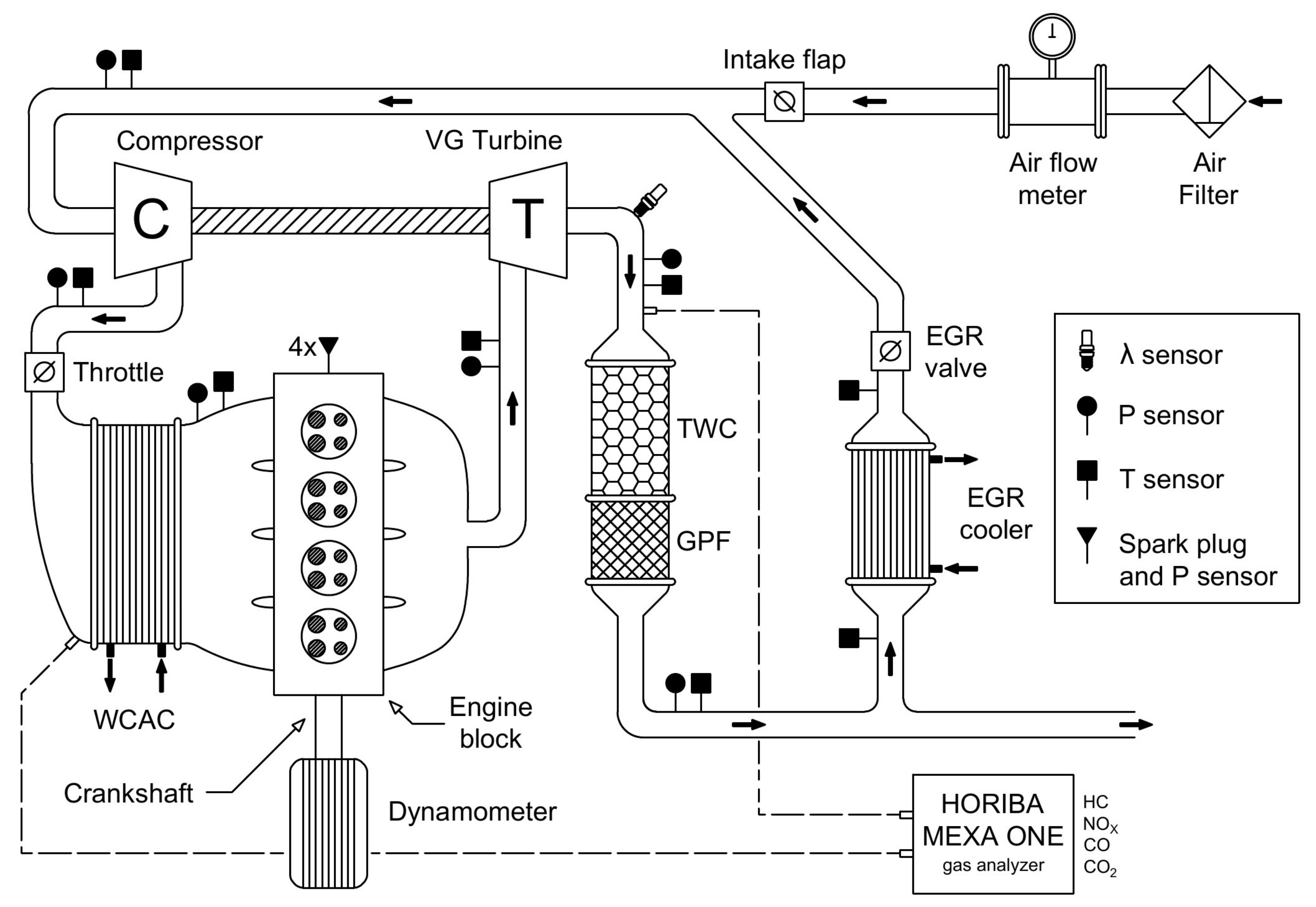
2.1. Engine Test Cell

A EURO VI 1.3L 4-stroke 4-cylinder turbocharged direct-injection SI engine was employed in this study, and its principal attributes are shown in Table 1. The engine also included the VGT, variable valve timing (VVT), and four-way catalyst (FWC) technologies. The latter is the combination of a conventional three-way catalyst with a gasoline particulate filter. Regarding the VVT system, the camshaft timing can be advanced or delayed in a range of 40° for both intake and exhaust sides, while the valve lift and opening durations are kept constant. In addition, a low-pressure EGR loop was appended to the base engine. It was composed of a T-shape flow splitter to extract the exhaust gases downstream of the aftertreatment, a water-to-air cooler, and an EGR valve [30]. A choke valve, named intake flap, was also installed in the main intake line, just upstream of the EGR junction, to operate with high EGR levels. A schematic engine layout is provided in Figure 1.
The engine was installed and fully instrumented in a dynamic test bench, which was managed with the AVL PUMA software. The engine speed and torque were regulated by means of an AVL AFA 200/4-8EU dynamometric brake. The AVL PUMA software was also used to record the main pressure and temperature values, air and fuel mass flows, turbocharger speed, and engine raw emissions, all with a 20 Hz acquisition frequency. The location of the pressure (Kistler 4260A piezoresistive type transmitters, Kistler Group, Milan, Italy) and temperature (3 mm K-type thermocouples) sensors can be observed in Figure 1. The turbocharger speed and the air and fuel mass flows were acquired with the devices MICRO-EPSILON DZ140, AVL FLOWSONIX, and AVL 733S, respectively; the HORIBA MEXA-ONE gas analyzer was utilized to register the measurements of NOx, HC, CO, CO2, and O2 [30].
Moreover, three Kistler 601CAA piezoelectric type sensors (Kistler Group, Milan, Italy) were installed to measure the instantaneous pressure traces at the compressor outlet and both manifolds, while four AVL Z133 spark plugs with integrated pressure sensors were utilized to register the in-cylinder pressure traces. All these signals were recorded with a sampling of 0.2 crank-angle degrees (CAD) by means of the PXI 6123 and PXI 6251 acquisition modules, both programmed with Labview by National InstrumentsTM (Austin, TX, USA) [31,32]. The original engine control unit (ECU), designed for the base engine without EGR, was partially bypassed with the ETAS ES910 prototyping and interface module to enable any variations on the VVT system, throttle position, spark timing, and injected fuel. The EGR valve, intake flap, and VGT position were directly controlled in open-loop configuration, independently of the ECU, through the PXI 7813R and NI 9759 control modules [31,32]. Finally, the ECU was also equipped with an air flowmeter at the air-filter outlet to ensure proper lambda control when operating with EGR.

2.2. Experimental Campaign

The objective of this research was to analyze the technical viability of dispensing with the compressor anti-surge valve in a turbocharged SI engine equipped with a low-pressure EGR loop. To this end, a series of tip-outs at 1500 rpm from full to zero load (the most critical surge conditions) was tested. Two strategies were studied in these tip-outs. First, the throttle closure was optimized to avoid instabilities in the compressor while ensuring a fast load decrease. Second, different closings on the intake flap were applied, and the throttle closure was re-optimized for each of them in order to evaluate the reduction of the compressor inlet pressure as a potential strategy to accelerate the maneuver. It must be remarked that the use of the intake flap does not involve an additional cost, given it is not an ad hoc solution to enhance the engine transient response without the ASV. As mentioned above, the installation of the intake flap is required to increase EGR rate and, consequently, fuel efficiency. Indeed, notable improvements in fuel consumption were achieved with high EGR operation in the same engine, as shown in a previous study [33]. In pursuit of simplicity, however, no EGR was used in the tests to reduce the degrees of freedom.
To optimize throttle closure, its actuation was divided into five transitions in which the time to reach five different openings was varied to find the surge limit. The throttle actuation of the 20 tip-outs tested for its optimization is shown in Figure 2. For all cases, the throttle position was automatically moved from 60 (fully open) to 40° in just one engine cycle (0.08 s), given that the air mass flow (AMF) was marginally modified in this opening range. For closer positions, the four transitions between openings equal to 40, 30, 20, 10, and 3° (minimum value to compensate friction losses) were optimized by testing five transition durations (1, 3, 5, 7, and 9 cycles), as seen in Figure 2. In descending order of duration, the optimum case was the one before the first in which compressor surge was detected.
Later, the effect of the intake flap on the surge limit was studied. Inducing a reduction in the compressor inlet pressure ( p 1 ) through the intake flap led to an increase in the corrected mass flow, thus moving to the right the operating point on the compressor map. In this research, three p 1 levels were evaluated if considering its minimum value during the tip-out maneuver: 0.33, 0.65, and 0.87 bar. Likewise, the throttle actuation was re-optimized for each p 1 level by following a similar procedure to the one described above.

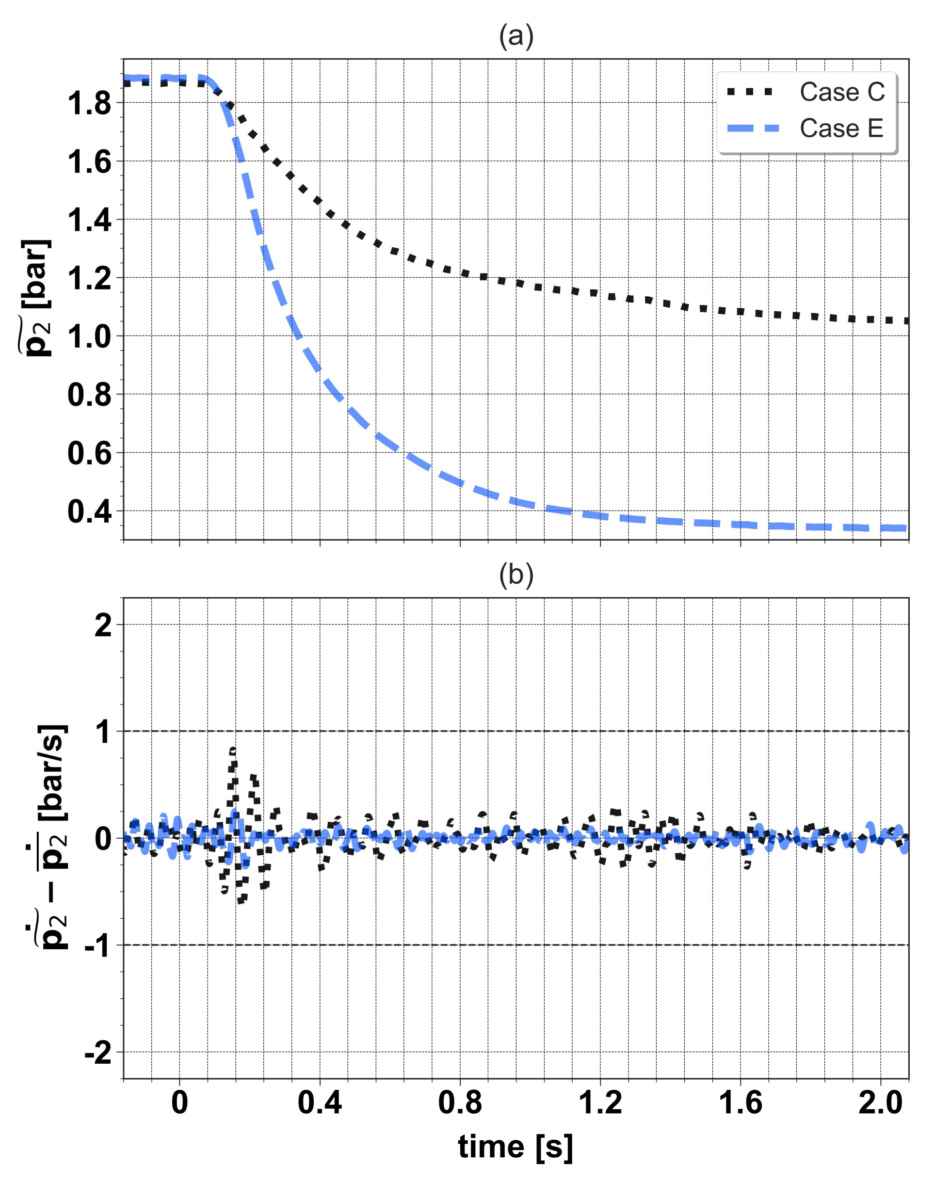
2.3. Surge Detection

The turbocharger was formerly characterized in a gas test stand according to the procedure explained by Serrano et al. [34], and the surge line was determined. However, this limit is not reliable once the turbocharger is coupled to the engine, because surge appearance is affected by the piping geometry around the compressor [19,20,21,22,23,24] and engine pulsation [25,26], as stated before. Besides, the surge margin may be modified under transient flow conditions [29]. Instead, the compressor outlet pressure ( p 2 ) signal, acquired with a sampling of 0.2 crank-angle degrees, and its first derivative were used for surge detection. The surge characteristic frequency is generally below 30 Hz [35], while the engine firing frequency with four cylinders at 1500 rpm is 50 Hz. Hence, the signals of p 2 were processed by means of a 5th order low-pass Butterworth filter [36] with a cut-off frequency ( f C ) of 30 Hz, to identify surge with no interference from engine pulses. The moving average of p 2 was also calculated by applying the same low-pass filter, but with an f C of 10 Hz to eliminate the oscillations due to the surge. The time derivative of the difference between the filtered pressure signal with a f C of 30 Hz ( p 2 ˜ ) and the moving average pressure signal ( p 2 ¯ ) was chosen as the main surge indicator, and an amplitude threshold of 1 bar/s was considered. In this way, an oscillation in that time derivative was regarded as surge if its amplitude was higher than 1 bar/s.

3. Results and Discussion

The experimental results of the tip-out maneuvers at 1500 rpm from full to zero load without ASV were arranged into two subsections: (i) optimization of throttle actuation to operate as close as possible to the surge limit and (ii) assessment of the effect of different intake flap closings on the surge margin to reduce maneuver duration.

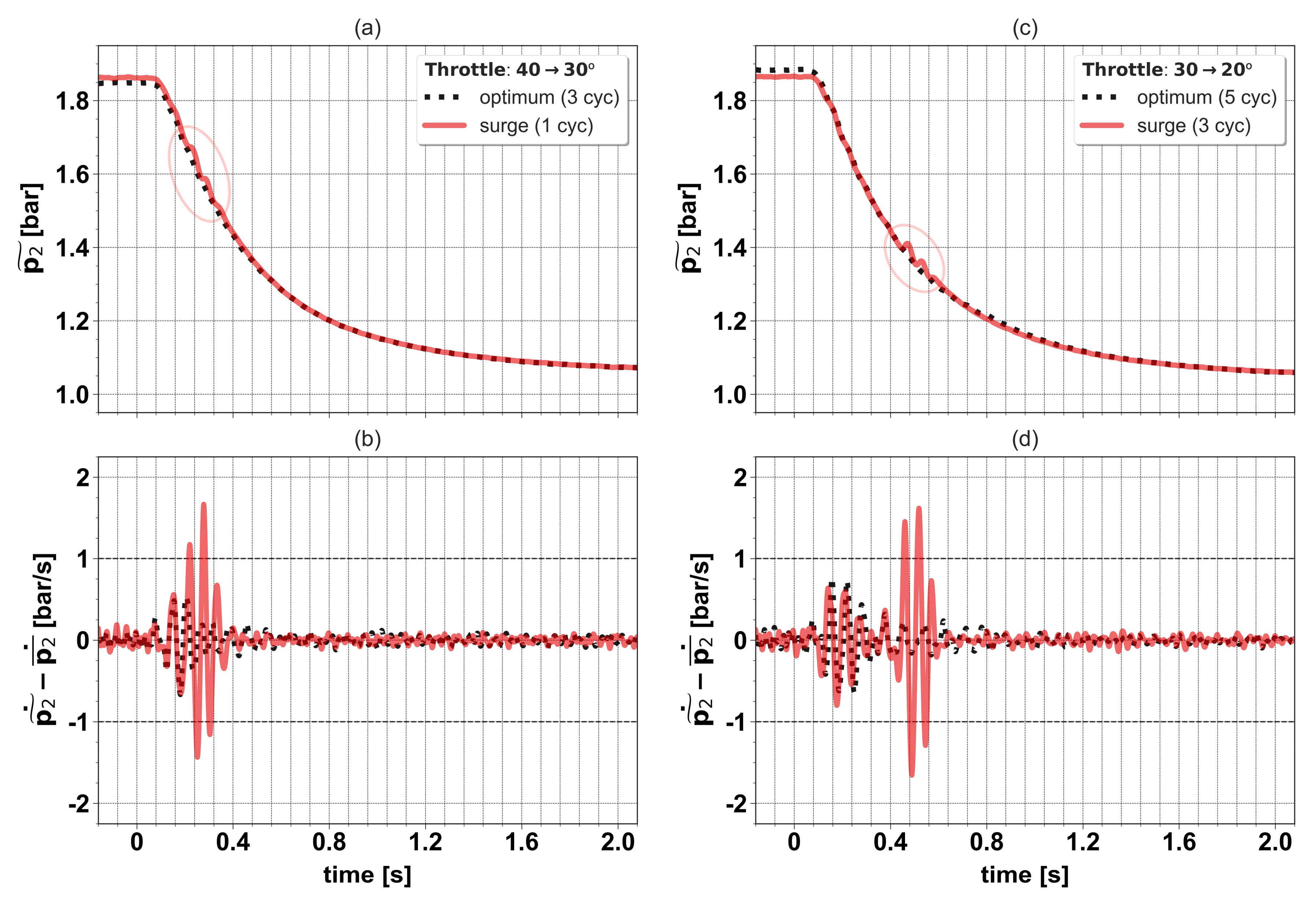
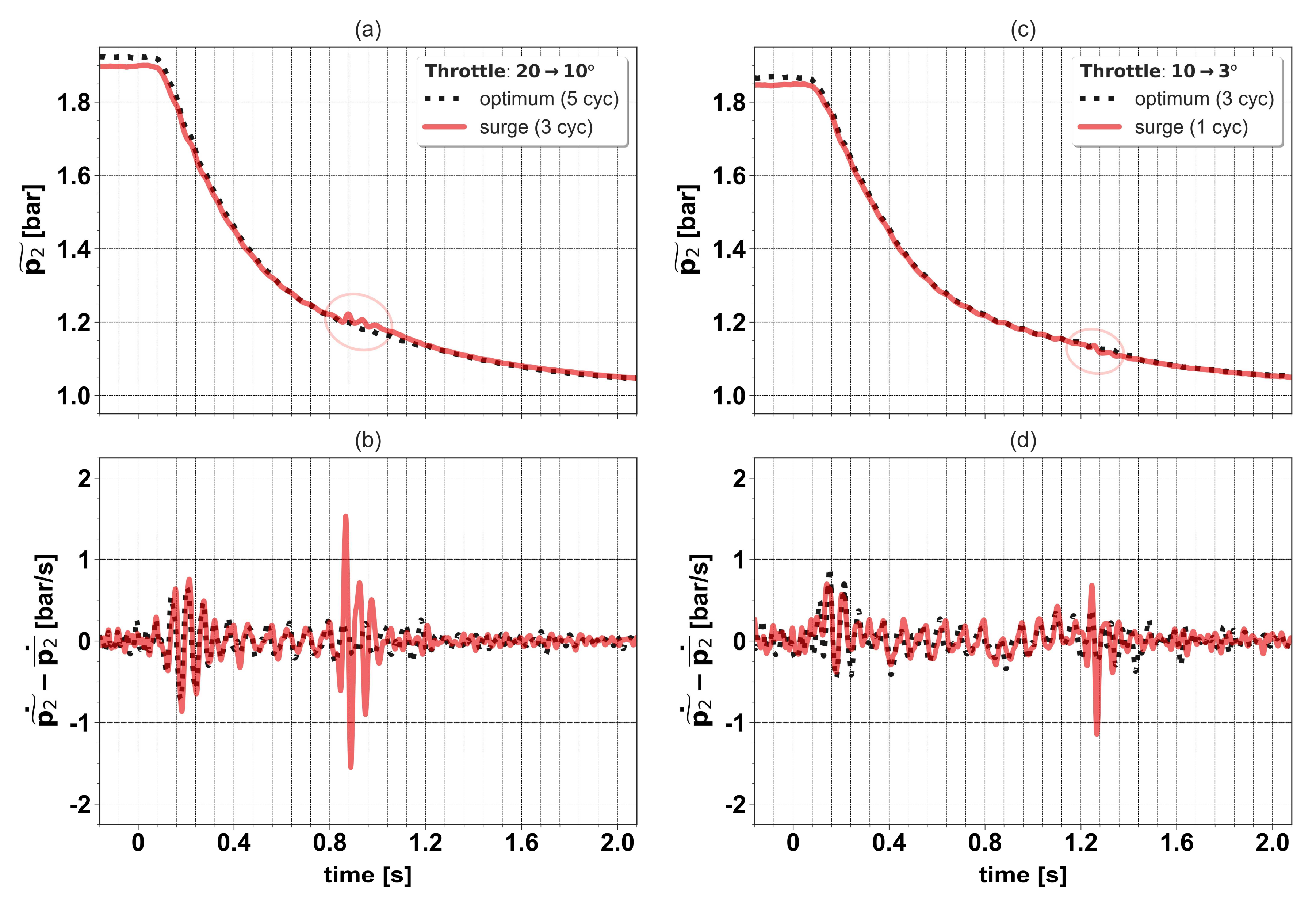
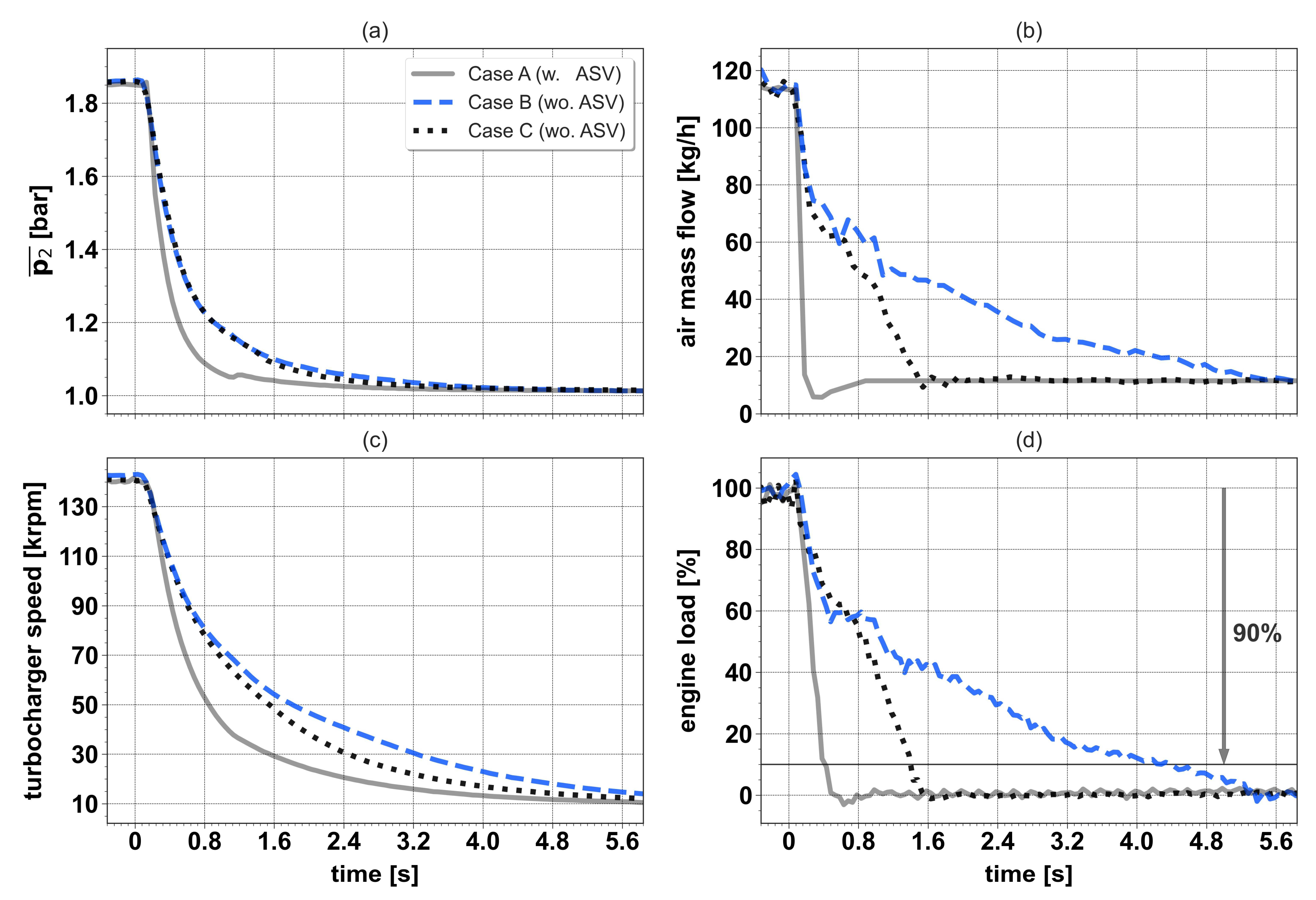
3.1. Optimization of Throttle Actuation

The throttle closure was optimized by varying the duration of the four transitions between the openings equal to 40, 30, 20, 10, and 3°, as stated in Section 2.2 (Figure 2). The objective was to find the fastest throttle closure which did not induce the appearance of compressor surge, without the aid of the anti-surge control system. Regarding the rest of the actuations, the VVT system was configured to provide a constant valve overlap of 40 CAD during the whole tip-out, and the VGT was fully open in 2 cycles from its full load position at the same timing as the throttle (that is, no delay between the start of the 2 actuations considered). Besides, the time profile of spark timing was defined to avoid knocking and misfires for all cases. As explained in Section 2.3, the compressor outlet pressure signal and its time derivative were processed and utilized to identify the surge.
Figure 3 and Figure 4 depict the evolution of p 2 ˜ and its time derivative ( p 2 ˜ ˙ p 2 ¯ ˙ ) for two cases per transition, i.e., in a descending order of duration, the first case where surge was detected and the previous one (which was the optimum). Taking into account the amplitude threshold of 1 bar/s for oscillations in the time derivative, the minimum durations without surge for the four transitions were respectively: 3, 5, 5, and 3 cycles. Thus, the optimum throttle actuation had a total duration of 17 engine cycles (around 1.4 s), including the cycle between throttle positions equal to 60 and 40.
Once the throttle actuation was optimized without the compressor ASV, two more tip-outs were tested: the reference case, in which the throttle was closed in two cycles using the anti-surge control system, and another tip-out with no ASV, where the throttle closure was designed to provide the closest operating path to the theoretical surge line on the compressor map. Figure 5 shows the throttle actuation (a) and compressor speed map (b) for these two tip-outs, respectively tagged as Case A and Case B, and the case with the throttle closure optimized with no ASV, labelled as Case C. In addition, the time evolution of compressor outlet pressure (a), air mass flow at filter outlet (b), turbocharger speed (c), and engine load (d) also for Case A, B, and C is presented in Figure 6.
Focusing on Cases B and C, the compressor operating path for the latter was clearly located to the left of the surge line, except for compression ratios between 1.2 and 1.4 (Figure 5b). This was reflected in the throttle actuation (Figure 5a), which was notably slower for Case B, mainly after the first second. Therefore, it was demonstrated that the surge line was not a reliable limit when the turbocharger, characterized in gas test stand, was coupled to the engine. Regarding Case A, it was observed that the throttle reached its minimum opening 1.2 s earlier than in Case B. These significant differences in throttle actuation were especially noticeable in the evolution of air mass flow and engine load (Figure 6). Hence, two remarks can be made in view of the results. After throttle closure optimization with no ASV, the compressor stable operation was ensured during the whole tip-out. However, it was found that the maneuver duration for Case C was extended for around 1 s, as compared to the time to complete the 90% of the total load reduction for Case A (Figure 6d).

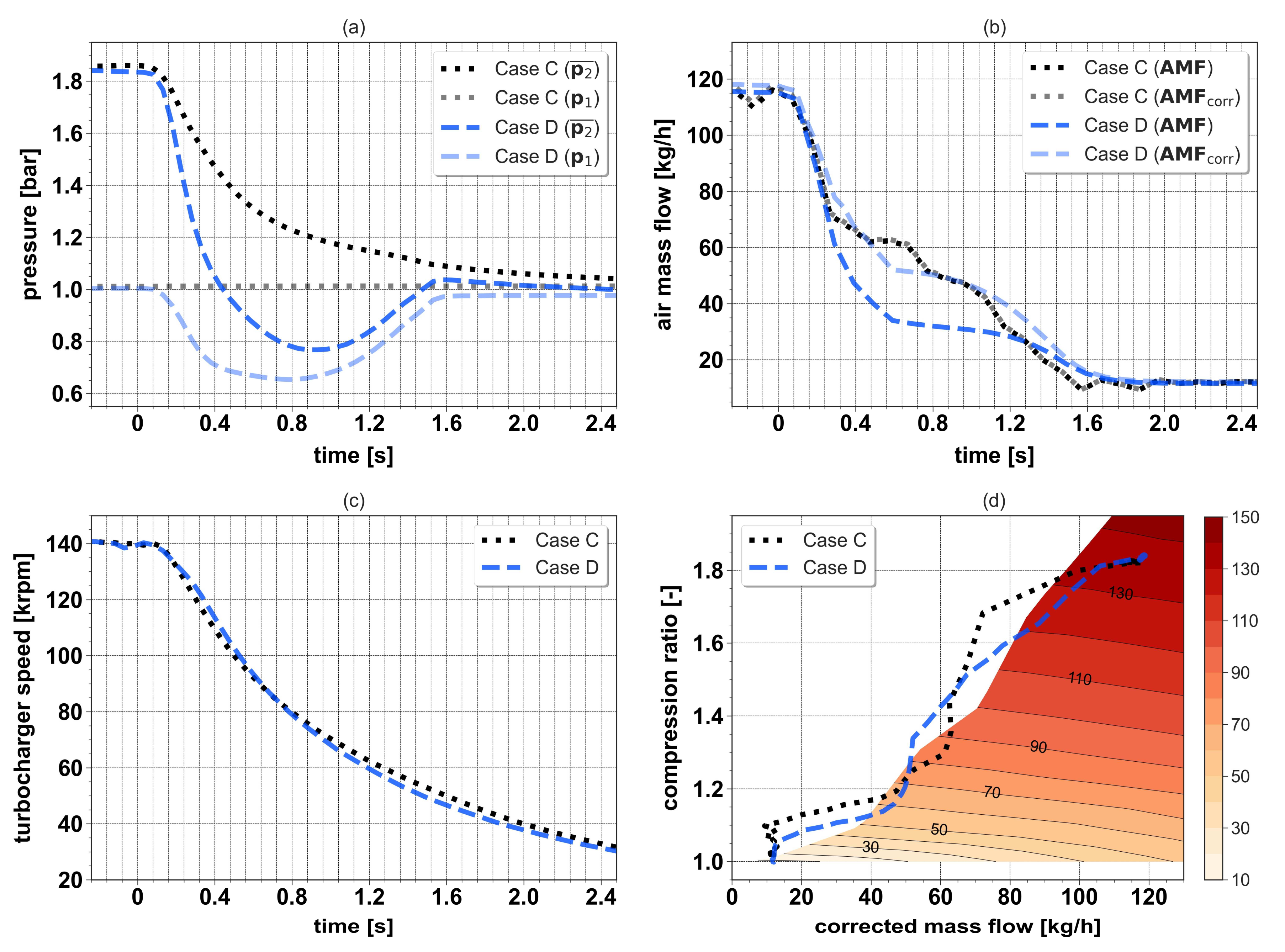
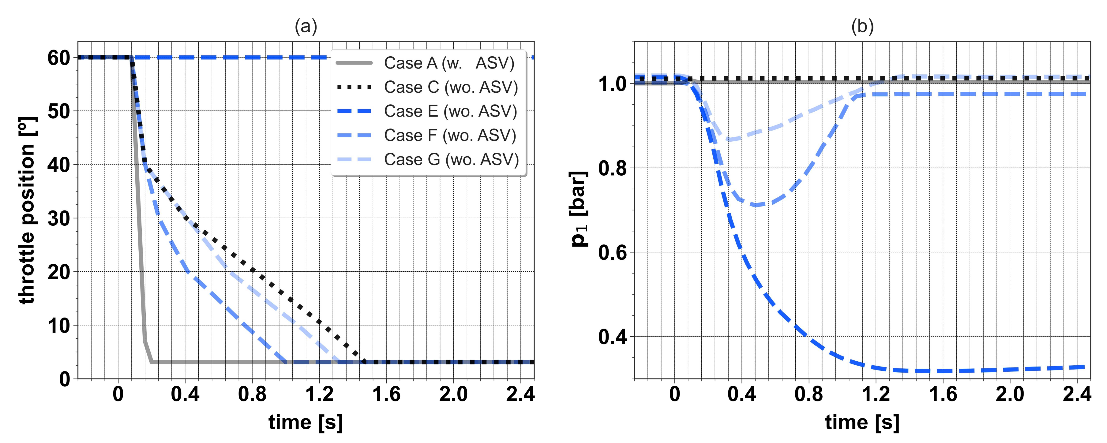
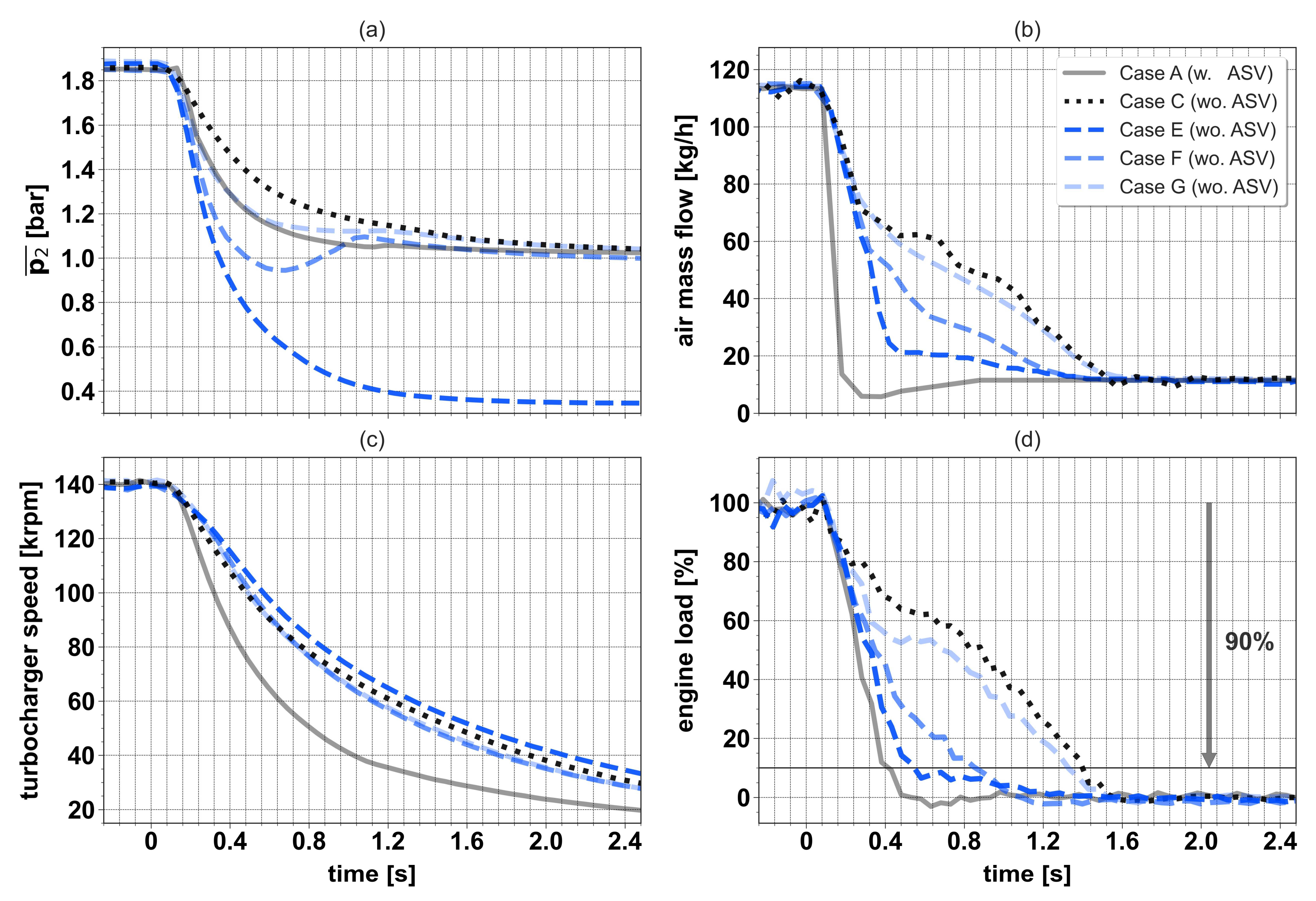
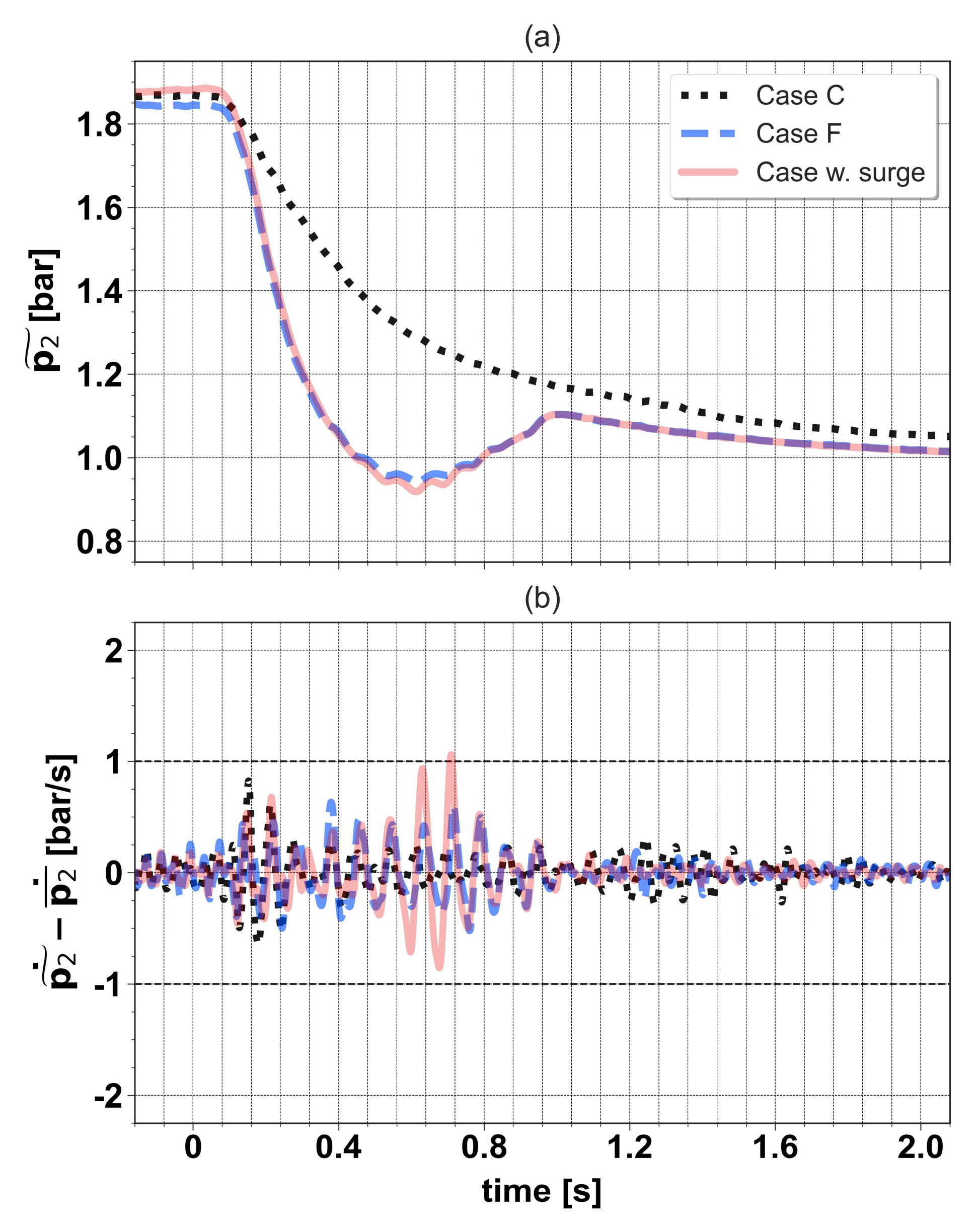
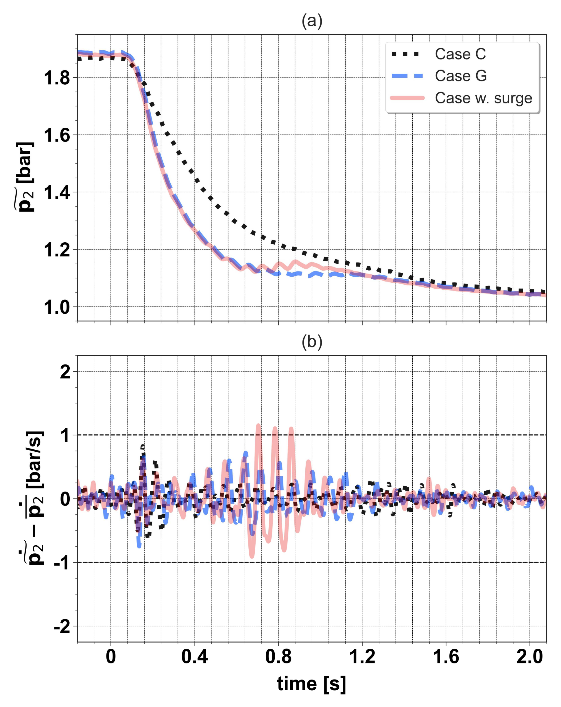
3.2. Effect of Intake Flap Closure on the Surge Margin

Another tip-out, tagged as Case D, was tested by using the same throttle actuation as in Case C and closing the intake flap from 100 to 6% opening in one engine cycle, with no delay between the two actuations. Figure 7 depicts the evolution of compressor inlet and outlet pressure (a), air mass flow at the filter outlet along with its corrected values (b) and turbocharger speed (c), and the operating path on the compressor speed map (d) for Case C and D, both with no ASV. Regarding Case D, p 1 decreased up to a minimum value of 0.65 bar at around 0.8 s (Figure 7a), then it recovered as the throttle closed and AMF was reduced. It must be clarified that the intake flap was not reopened during the tip-out. Despite the p 1 decrease leading to a faster reduction of the air mass flow in Case D from 0.2 to 1.2 s, slight differences between both cases were noticed in terms of corrected AMF (Figure 7b). This was reflected in the operating path on the compressor map (Figure 7d), where it is observed that there was even a margin to apply a more aggressive throttle closure in Case D at the start and at the end of the maneuver, given that the operating path of Case C set the surge limit a priori.
Once the capability of intake flap closure to accelerate the maneuver was confirmed, three p 1 levels were analyzed (considering its minimum value): 0.33, 0.65, and 0.87 bar. In the first case, load reduction was only achieved through the intake flap, while the throttle was kept open during the whole maneuver. For the other two p 1 levels, throttle actuation was re-optimized by following a similar procedure to the one described in Figure 2. It should be stated that intake flap closing was demanded in one cycle, from full opening to its corresponding final position (2, 6, and 12%, in ascending order of p 1 ), and that no delay between the start of throttle and intake flap actuations was applied. Figure A1, Figure A2 and Figure A3 (Appendix A) show the evolution of the compressor outlet pressure and its time derivative for three cases per each p 1 level: the best tip-out for each intake flap closing, labelled as Case E ( p 1 = 0.33), F ( p 1 = 0.65) or G ( p 1 = 0.87), a tip-out with a more aggressive throttle actuation for the two highest p 1 levels, in which surge was detected, and the best case with throttle only (Case C). It must be emphasized that no surge was found for the tip-out managed only with the intake flap (Case E), despite its closing in one cycle. For the sake of readability, a summary of the different cases analyzed is provided in Table 2, where throttle and intake flap actuations, p 1 level, and the use of ASV in each case are specified.
Figure 8 and Figure 9 depict throttle actuation and time evolution of the compressor inlet and outlet pressure, air mass flow at filter outlet, turbocharger speed, and engine load for five tip-outs: Cases A, C, E, F, and G. It should be reminded that the first one was tested with the anti-surge valve, while the remaining ones were performed without it. As observed in Figure 8a, the throttle could be closed two and six cycles faster in Cases F and G, as compared to Case C, due to p 1 decrease up to 0.65 and 0.87 bar, respectively. The reduction of air mass flow and engine load is consequently accelerated. In particular, the maneuver duration in Case F was just 0.4 s longer than in the reference tip-out (Case A), considering, again, the time to complete the 90% of the total load reduction (Figure 9d). After that, it can be concluded that the use of intake flap to perform the tip-out with no ASV allowed ensuring the compressor stable operation, without compromising the engine transient response in excess. Indeed, the reduction of engine load in Case A and Case E was quite similar (Figure 9d). By contrast, it would be necessary to analyze if such momentary low p 1 levels can cause oil leakages in the turbocharger, but this falls beyond the scope of this research.

4. Conclusions

The technical viability of eliminating the compressor anti-surge valve (ASV) in a turbocharged SI engine, equipped with a low-pressure EGR loop, was assessed in this study, in the interest of cost reduction. To this end, a series of tip-out maneuvers from full to zero load at 1500 rpm was tested, without the compressor ASV, to evaluate two alternative strategies to this anti-surge control system: the optimization of throttle closure to achieve a load decrease as fast as possible without compressor surge, and the application of different closings on the intake flap, located upstream of the compressor, to accelerate the maneuver. The time derivative of the filtered crank-angle resolved pressure signal at the compressor outlet was used as the main surge indicator.
The optimization of throttle actuation with no ASV, while keeping open the intake flap, enabled to ensure the compressor stable operation for the whole tip-out. Nevertheless, the maneuver duration was extended for around 1s, as compared with the time to reach 10% load in the reference case with ASV. When the intake flap was also actuated, the load decrease could be accelerated. The tip-out duration in the case where the compressor inlet pressure was reduced up to 0.65 bar was just 0.4 s longer than in the reference case. In the case that the compressor inlet pressure was further decreased until 0.33 bar, unnoticeable differences in terms of engine load were observed with respect to the reference. Therefore, it is concluded that the role of the compressor ASV can be assigned to the intake flap, required at the compressor inlet for high EGR operation, without compromising the compressor stable operation and engine load reduction.

Author Contributions

Conceptualization, J.G., J.d.l.M., S.G. and T.B.; methodology, J.G., H.C. and J.d.l.M.; software, H.C.; formal analysis, H.C. and D.G.-D.; investigation, J.d.l.M. and D.G.-D.; resources, S.G. and T.B.; writing—original draft preparation, H.C. and D.G.-D.; writing—review and editing, J.G., J.d.l.M., H.C., D.G.-D., S.G. and T.B.; visualization, D.G.-D.; supervision, J.G., J.d.l.M. and T.B.; project administration, J.G. and S.G.; funding acquisition, S.G. and T.B. All authors have read and agreed to the published version of the manuscript.

Funding

This research received no external funding.

Data Availability Statement

The data that support the findings of this study are not available due to privacy restrictions.

Acknowledgments

The authors would like to thank Vicente Esteve, Rafael Pitarch, and Irina Jimenez for their invaluable work during the experimental campaign.

Conflicts of Interest

The authors declare no conflict of interest. The funders had no role in the design of the study; in the collection, analyses, or interpretation of data; in the writing of the manuscript, or in the decision to publish the results.

Nomenclature

Acronyms and abbreviations
AMF air mass flow
ASVanti-surge valve
CADcrank-angle degrees
cyc.cycle
ECUengine control unit
EGRexhaust gas recirculation
SIspark ignition
VGTvariable geometry turbine
VVTvariable valve timing
w.with
wo.without
Symbols
f frequency
p pressure signal
p ˜ filtered pressure signal ( f C = 30 Hz)
p ¯ moving average pressure signal ( f C = 10 Hz)
p ˜ ˙ time derivative of p ˜
p ¯ ˙ time derivative of p ¯
Subscripts
1compressor inlet
2compressor outlet
ccut-off
corrcorrected

Appendix A

The time evolution of the compressor outlet pressure and its time derivative for three cases per each p 1 level (0.33, 0.65 and 0.87 bar) is presented in Figure A1, Figure A2 and Figure A3, in relation to the re-optimization of throttle actuation.
Figure A1. Time evolution of compressor outlet pressure (a) and its time derivative (b) for Case C and Case E.
Applsci 12 01751 g0a1
Figure A2. Time evolution of compressor outlet pressure (a) and its time derivative (b) for Case C, Case F, and a case with surge, in relation to the re-optimization of the throttle actuation for the p 1 level equal to 0.65 bar.
Applsci 12 01751 g0a2
Figure A3. Time evolution of compressor outlet pressure (a) and its time derivative (b) for Case C, Case G, and a case with surge, in relation to the re-optimization of the throttle actuation for the p 1 level equal to 0.87 bar.
Applsci 12 01751 g0a3

References

  1. García, A.; Monsalve-Serrano, J.; Martínez-Boggio, S.; Wittek, K. Potential of hybrid powertrains in a variable compression ratio downsized turbocharged VVA Spark Ignition engine. Energy 2020, 195, 117039. [Google Scholar] [CrossRef]
  2. Conway, G.; Chambon, P.; Alger, T. Opportunities for Electrified Internal Combustion Engines; SAE Technical Paper 2020-01-0281; SAE International: Detroit, MI, USA, 2020. [Google Scholar] [CrossRef]
  3. Soleimani, M.; Campean, F.; Neagu, D. Reliability challenges for automotive aftertreatment systems: A state-of-the-art perspective. Procedia Manuf. 2018, 16, 75–82. [Google Scholar] [CrossRef]
  4. Lumsden, G.; OudeNijeweme, D.; Fraser, N.; Blaxill, H. Development of a Turbocharged Direct Injection Downsizing Demonstrator Engine. SAE Int. J. Engines 2009, 2, 1420–1432. [Google Scholar] [CrossRef] [Green Version]
  5. Shahed, S.M.; Bauer, K.-H. Parametric Studies of the Impact of Turbocharging on Gasoline Engine Downsizing. SAE Int. J. Engines 2009, 2, 1347–1358. [Google Scholar] [CrossRef]
  6. Fontana, G.; Galloni, E. Variable valve timing for fuel economy improvement in a small spark-ignition engine. Appl. Energy 2009, 86, 96–105. [Google Scholar] [CrossRef]
  7. Parker, M.C.; Jiang, C.; Butcher, D.; Spencer, A.; Garner, C.P.; Witt, D. Impact and observations of cylinder deactivation and reactivation in a downsized gasoline turbocharged direct injection engine. Int. J. Engine Res. 2021, 22, 1367–1376. [Google Scholar] [CrossRef] [Green Version]
  8. Golzari, R.; Zhao, H.; Hall, J.; Bassett, M.; Williams, J.; Pearson, R. Impact of intake port injection of water on boosted downsized gasoline direct injection engine combustion, efficiency and emissions. Int. J. Engine Res. 2021, 22, 295–315. [Google Scholar] [CrossRef]
  9. Luján, J.M.; Climent, H.; Novella, R.; Rivas-Perea, M.E. Influence of a low pressure EGR loop on a gasoline turbocharged direct injection engine. Appl. Therm. Eng. 2015, 89, 432–443. [Google Scholar] [CrossRef] [Green Version]
  10. Siokos, K.; Koli, R.; Prucka, R.; Schwanke, J.; Miersch, J. Assessment of Cooled Low Pressure EGR in a Turbocharged Direct Injection Gasoline Engine. SAE Int. J. Engines 2015, 8, 1535–1543. [Google Scholar] [CrossRef]
  11. Macián, V.; Tormos, B.; Bermúdez, V.; Ramírez, L. Assessment of the effect of low viscosity oils usage on a light duty diesel engine fuel consumption in stationary and transient conditions. Tribol. Int. 2014, 79, 132–139. [Google Scholar] [CrossRef]
  12. Zeppei, D.; Koch, S.; Rohi, A. Ball Bearing Technology for Passenger Car Turbochargers. MTZ Worldw. 2016, 77, 26–31. [Google Scholar] [CrossRef]
  13. Hu, B.; Akehurst, S.; Lewis, A.G.; Lu, P.; Millwood, D.; Copeland, C.; Chappell, E.; De Freitas, A.; Shawe, J.; Burtt, D. Experimental analysis of the V-Charge variable drive supercharger system on a 1.0 L GTDI engine. Proc. Inst. Mech. Eng. Part D J. Automob. Eng. 2018, 232, 449–465. [Google Scholar] [CrossRef]
  14. Lefebvre, A.; Guilain, S. Transient Response of a Turbocharged SI Engine with an Electrical Boost Pressure Supply; SAE Technical Paper 2003-01-1844; SAE International: Warrendale, PA, USA, 2003. [Google Scholar] [CrossRef]
  15. Hu, B.; Yang, J.; Li, J.; Li, S.; Bai, H. Intelligent control strategy for transient response of a variable geometry turbocharger system based on deep reinforcement learning. Processes 2019, 7, 601. [Google Scholar] [CrossRef] [Green Version]
  16. Tang, H.; Akehurst, S.; Brace, C.J.; Garrett, S.; Smith, L. Optimisation of transient response of a gasoline engine with variable geometry turbine turbocharger. In Proceedings of the Institution of Mechanical Engineers: 11th International Conference on Turbochargers and Turbocharging, London, UK, 13–14 May 2014; pp. 163–175. [Google Scholar] [CrossRef]
  17. Andersen, J.; Lindström, F.; Westin, F. Surge Definitions for Radial Compressors in Automotive Turbochargers. SAE Int. J. Engines 2009, 1, 218–231. [Google Scholar] [CrossRef]
  18. Kurz, R.; White, R.C. Surge Avoidance in Gas Compression Systems. ASME. J. Turbomach. 2004, 126, 501–506. [Google Scholar] [CrossRef]
  19. Oakes, W.C.; Lawless, P.B.; Fagan, J.R.; Fleeter, S. High-speed centrifugal compressor surge initiation characterization. J. Propuls. Power 2002, 18, 1012–1018. [Google Scholar] [CrossRef]
  20. Engeda, A.; Kim, Y.; Aungier, R.; Direnzi, G. The inlet flow structure of a centrifugal compressor stage and its influence on the compressor performance. J. Fluids Eng. 2003, 125, 779–785. [Google Scholar] [CrossRef]
  21. Galindo, J.; Arnau, F.; Tiseira, A.; Lang, R.; Lahjaily, H.; Gimenes, T. Measurement and Modeling of Compressor Surge on Engine Test Bench for Different Intake Line Configurations; SAE Technical Paper 2011-01-0370; SAE International: Warrendale, PA, USA, 2011. [Google Scholar] [CrossRef]
  22. Galindo, J.; Tiseira, A.; Navarro, R.; Tarí, D.; Meano, C.M. Effect of the inlet geometry on performance, surge margin and noise emission of an automotive turbocharger compressor. Appl. Therm. Eng. 2017, 110, 875–882. [Google Scholar] [CrossRef]
  23. Fink, D.A.; Cumpsty, N.A.; Greitzer, E.M. Surge Dynamics in a Free-Spool Centrifugal Compressor System. ASME. J. Turbomach. 1992, 114, 321–332. [Google Scholar] [CrossRef]
  24. Galindo, J.; Serrano, J.R.; Climent, H.; Tiseira, A. Experiments and modelling of surge in small centrifugal compressor for automotive engines. Exp. Therm. Fluid Sci. 2008, 32, 818–826. [Google Scholar] [CrossRef]
  25. Galindo, J.; Serrano, J.R.; Margot, X.; Tiseira, A.; Schorn, N.; Kindl, H. Potential of flow pre-whirl at the compressor inlet of automotive engine turbochargers to enlarge surge margin and overcome packaging limitations. Int. J. Heat Fluid Flow 2007, 28, 374–387. [Google Scholar] [CrossRef]
  26. Galindo, J.; Climent, H.; Guardiola, C.; Tiseira, A. On the effect of pulsating flow on surge margin of small centrifugal compressors for automotive engines. Exp. Therm. Fluid Sci. 2009, 33, 1163–1171. [Google Scholar] [CrossRef]
  27. Lujan, J.; Pastor, J.; Climent, H.; Rivas, M. Experimental Characterization and Modelling of a Turbocharger Gasoline Engine Compressor By-Pass Valve in Transient Operation; SAE Technical Paper 2015-24-2524; SAE International: Warrendale, PA, USA, 2015. [Google Scholar] [CrossRef]
  28. Ossareh, H.R.; Buckland, J.; Jankovic, M. Continuous compressor recirculation to improve boost response and mitigate compressor surge in turbocharged gasoline engines. In Proceedings of the 2016 American Control Conference (ACC), Boston, MA, USA, 6–8 July 2016; pp. 5093–5098. [Google Scholar] [CrossRef]
  29. Podevin, P.; Danlos, A.; Deligant, M.; Punov, P.; Clenci, A.; de La Bourdonnaye, G. Automotive compressor: Effect of an electric throttle in the upstream circuit on the surge limit. MATEC Web Conf. 2018, 234, 03006. [Google Scholar] [CrossRef] [Green Version]
  30. Galindo, J.; Climent, H.; de la Morena, J.; González-Domínguez, D.; Guilain, S.; Besançon, T. Assessment of air-management strategies to improve the transient performance of a gasoline engine under high EGR conditions during load-decrease operation. Int. J. Engine Res. 2021. [Google Scholar] [CrossRef]
  31. Pla, B.; De La Morena, J.; Bares, P.; Jiménez, I. Knock Analysis in the Crank Angle Domain for Low-Knocking Cycles Detection; SAE Technical Paper 2020-01-0549; SAE International: Warrendale, PA, USA, 2020. [Google Scholar] [CrossRef]
  32. Pla, B.; De la Morena, J.; Bares, P.; Jiménez, I. Cycle-to-cycle combustion variability modelling in spark ignited engines for control purposes. Int. J. Engine Res. 2020, 21, 1398–1411. [Google Scholar] [CrossRef]
  33. Galindo, J.; Climent, H.; De la Morena, J.; González-Domínguez, D.; Guilain, S.; Besançon, T. Experimental and modeling analysis on the optimization of combined VVT and EGR strategies in turbocharged direct-injection gasoline engines with VNT. Proc. Inst. Mech. Eng. Part D J. Automob. Eng. 2021, 235, 2843–2856. [Google Scholar] [CrossRef]
  34. Serrano, J.R.; Arnau, F.J.; García-Cuevas, L.M.; Gómez-Vilanova, A.; Guilain, S.; Batard, S. A Methodology for Measuring Turbocharger Adiabatic Maps in a Gas-Stand and Its Usage for Calibrating Control Oriented and One-Dimensional Models at Early ICE Design Stages. ASME. J. Energy Resour. Technol. 2021, 143, 042303. [Google Scholar] [CrossRef]
  35. Galindo, J.; Serrano, J.R.; Guardiola, C.; Cervelló, C. Surge limit definition in a specific test bench for the characterization of automotive turbochargers. Exp. Therm. Fluid Sci. 2006, 30, 449–462. [Google Scholar] [CrossRef]
  36. Ellis, G. Chapter 9—Filters in Control Systems. In Control Systems Design Guide, 4th ed.; Ellis, G., Ed.; Butterworth-Heinemann: Oxford, UK, 2012; pp. 165–183. [Google Scholar] [CrossRef]
Figure 1. Schematic engine layout.
Applsci 12 01751 g001
Figure 2. Optimization of throttle closure.
Applsci 12 01751 g002
Figure 3. Time evolution of compressor outlet pressure and its time derivative for two cases of the transitions 40–30° (a,b) and 30–20° (c,d). In the insets, the duration of the transition is stated between parentheses.
Applsci 12 01751 g003
Figure 4. Time evolution of compressor outlet pressure and its time derivative for two cases of the transitions 20–10° (a,b) and 10–3° (c,d). In the insets, the duration of the transition is stated between parentheses.
Applsci 12 01751 g004
Figure 5. Throttle actuation (a) and compressor speed map (b) for Cases A, B, and C. The corrected compressor speed values are given in kRPM.
Applsci 12 01751 g005
Figure 6. Time evolution of compressor outlet pressure (a), air mass flow at filter outlet (b), turbocharger speed (c), and engine load (d) for Cases A, B, and C.
Applsci 12 01751 g006
Figure 7. Time evolution of compressor inlet and outlet pressure (a), air mass flow at filter outlet along with its corrected values (b) and turbocharger speed (c), and operating path on the compressor speed map (d) for Cases C and D.
Applsci 12 01751 g007
Figure 8. Throttle actuation (a) and time evolution of compressor inlet pressure (b) for Cases A, C, E, F, and G.
Applsci 12 01751 g008
Figure 9. Time evolution of compressor outlet pressure (a), air mass flow at filter outlet (b), turbocharger speed (c), and engine load (d) for Cases A, C, E, F, and G.
Applsci 12 01751 g009
Table 1. Engine’s attributes.
AttributeDescription
TypeGasoline Euro VI
Displacement1300 cc
Compression ratio10:1
Number of cylinders4
Type of injectionDirect injection
Camshaft systemVariable Valve Timing
Total number of valves (intake/exhaust)8/8
TurbochargerVGT technology
Aftertreatment systemFour-way catalyst
Table 2. Summary of the main features of Case A, B, C, D, E, F and G.
CaseThrottle ActuationIntake Flap p 1   Level ASV
Aclosed in two cyclesfully openambientYes
Bdefined to follow surge linefully openambientNo
Coptimizedfully openambientNo
Dsame as Cclosed until 6% in one cycle0.65 barNo
Efully openclosed until 2% in one cycle0.33 barNo
Fre-optimizedclosed until 6% in one cycle0.65 barNo
Gre-optimizedclosed until 12% in one cycle0.87 barNo
Publisher’s Note: MDPI stays neutral with regard to jurisdictional claims in published maps and institutional affiliations.

