
Research on Influence of Switching Angle on the Vibration of Switched Reluctance Motor


1
School of Mechatronic Engineering and Automation, Shanghai University, Shanghai 200072, China
2
School of Mechanical Engineering, Shanghai Jiao Tong University, Shanghai 200240, China
*
Author to whom correspondence should be addressed.
Appl. Sci. 2022, 12(9), 4793; https://0-doi-org.brum.beds.ac.uk/10.3390/app12094793
Submission received: 23 April 2022
/
Revised: 6 May 2022
/
Accepted: 7 May 2022
/
Published: 9 May 2022
(This article belongs to the Special Issue Machine Learning in Vibration and Acoustics)
Abstract
:Switched Reluctance Motors (SRMs) have emerged as a viable competitor to other established electrical machines. Although SRMs have many advantages, such as a rare earth free nature, simple structure, high fault tolerance capability and low cost, vibration problems due to radial force variations is still a major issue faced by SRMs. Hence, aimed at the problem of vibration suppression for SRMs, this paper proposes a method that focuses on the influence of the change of the turn-on angle and turn-off angle on the vibration of the SRM under the switching angle control (SAC) strategy. Firstly, the influence of the turn-on and turn-off angles on the harmonic components of the current is analyzed in detail. Then, the vibration caused by the frequency of the harmonic components of the current and the natural frequency of the motor is mainly studied. The results show that the harmonic order affecting vibration is related to the rotational speed, and by analyzing the value of this harmonic order, the variation law of vibration with the switching angle can be obtained. When the turn-off angle is constant, the amplitudes of the current harmonic component and vibration first decrease and then increase with the increase of the turn-on angle. Additionally, when the turn-on angle is constant, the current harmonic and vibration show the tendency of periodic oscillation with the variation of the turn-off angle, and the oscillation period is related to the harmonic order. The combination of switching angles that minimizes the certain current harmonic component also minimizes vibration. The effectiveness of the variation law was verified on a 12/8 poles and 1.5 KW SRM drive system test bench, which provide a new perspective on vibration suppression of SRMs.
1. Introduction
A switched reluctance motor (SRM) is known for its simple construction, robustness, inherent fault tolerant structure and low production costs [1,2,3]. However, due to the double salient pole structure and switching operation mode of the SRM, it will generate a pulsating radial force during operation, and the radial force acts on the electronic stator to cause vibration and acoustic noise, which limits its application in the industrial potential market [4,5]. The existing research to suppress vibration for an SRM is mainly divided into two categories; the first category is to change the motor topology structure from the aspect of motor design, whereas the second one is to realize the vibration suppression of the SRM by the control strategy. In terms of optimal design of the motor structure, vibration suppression is mainly achieved by changing the structure of the motor body. For instance, Yang et al. [6] and Gan et al. [7] proposed one-phase and three-phase salient-pole SRMs, respectively. Isfahani and Fahimi [8] proposed a dual-stator SRM, which proved that the double stator structure can effectively reduce the vibration. Widmer et al. [9] proposed an optimized segmental rotor SRM with a greater number of rotor segments than stator slots. Kurihara et al. [10] realized vibration reduction of the SRM with a high number of poles. There is lots of research on vibration suppression from the aspect of control strategy, such as, switching angle adjustment [11], inserting of zero voltage loop during switching [12] and current waveform profiling [13,14]. Among them, switching angle adjustment is widely used due to its simple implementation.
In the control strategy of the switched reluctance motor, the turn-on angle and the turn-off angle are two important control parameters that have a direct impact on the performance parameters of the switched reluctance motor, such as torque, torque ripple, efficiency, vibration and noise [15,16]. The way of controlling the operation of the switched reluctance motor by adjusting the turn-on angle and turn-off angle is called switching angle control (SAC), and this method is widely used because of its simplicity [17,18]. The main control parameters of the SAC control strategy include turn-on angle, turn-off angle and duty cycle. Studies have shown that limiting the current change rate by adjusting the switching angle can effectively reduce the vibration and noise of the switched reluctance motor [19,20]. At present, scholars at home and abroad have carried out research on the optimization of switching angle. For example, Bayless et al. [21] achieved the vibration reduction goal by randomly adjusting the turn-off angle. Desai et al. [22] compared the switching angle random adjustment method with other vibration reduction methods and verified the effectiveness of the random adjustment of the switching angle method. Xu et al. [23] considered the influence of back EMF and proposed an analytical model of the turn-on angle and turn-off angle and optimized the turn-on angle based on the model. However, there is still a lack of research on the influence of the switching angle on the vibration of the switched reluctance motor, and the switching angle optimization algorithm has shortcomings, such as low efficiency.
This manuscript focuses on the influence of the change of turn-on angle and turn-off angle on the vibration of a switched reluctance motor under the angle control strategy. The influence of on angle and off angle on a current harmonic component is analyzed in detail, and the vibration caused by the consistency of current harmonic component frequency and motor natural frequency is studied. Then, the effectiveness of the proposed method was verified on a 12/8 poles and 1.5 KW SRM drive system test bench. In Section 2, the principle of the switching angle control method is presented. Section 3 shows the influence of the switching angle on vibration of an SRM. In Section 4, the experimental verification and analysis is implemented to validate the proposed method. Finally, the conclusion is drawn in Section 5.
2. Principle of Switching Angle control Method
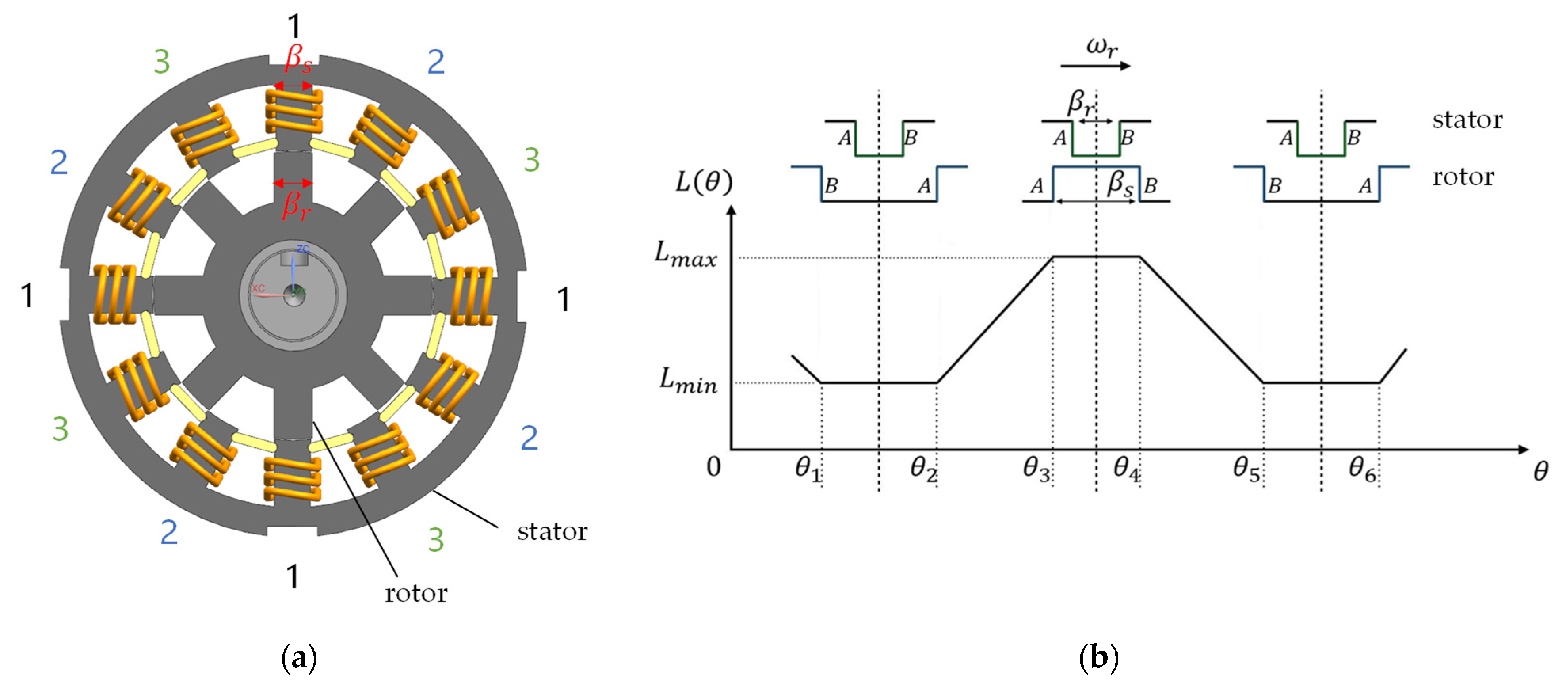
A typical structure of stator and rotor for a 12-8 SRM is shown in Figure 1a. As can be seen from the figure, both the stator and the rotor of the SRM are doubly salient structures. If a specific phase of the motor (e.g., phase 1) is excited, the magnetic field force is generated due to the distortion of the electromagnetic field, which makes the rotor rotate to the position where the pole axis of the rotor and the pole axis of the stator coincide. When the phases 2, 3, 1 and 2 in Figure 1a are sequentially energized, the rotor will continuously rotate in a counterclockwise direction, and, vice versa, in a clockwise direction. Due to the double salient pole structure and unique switching mode of the switched reluctance motor, the flux linkage of the switched reluctance motor has strong nonlinearity, which makes the mathematical model of the switched reluctance motor very complex. In order to facilitate the analysis, on the basis of ignoring the flux saturation effect and reluctance edge effect, this section linearizes and simplifies the flux linkage characteristics of switched reluctance motor. In the linearized model, the inductance is related to the rotor position and independent of the current. For a phase of the switched reluctance motor, during the rotation, the relative positions of salient poles of stator and rotor change periodically, and the inductance also changes periodically between the maximum value Lmax and the minimum value Lmin. The change curve of inductance relative to rotor position is shown in Figure 1b, where βr is the length of stator pole arc, βs is the length of rotor pole arc, θ1 is the position where side B of stator and side a of rotor coincide, θ2 is the position where side a of stator and side B of rotor coincide, θ3 is the position where stator side B and rotor side B coincide, θ4 is the position where side a of stator and side a of rotor coincide, θ5 is the position where stator side B and rotor side a coincide and θ6 is the coincidence position of stator side a and rotor side B.
Figure 1b also shows the variation curve of the inductance with respect to the rotor angle position θ under the linear model, where θ1 to θ5 is an electrical cycle. When θ1 ≤ θ < θ2, the stator salient pole and rotor groove overlap, and the air gap between stator and rotor is the largest, so the magnetic resistance is the largest and the inductance is the smallest. When θ2 ≤ θ < θ3, the rotor salient pole begins to overlap with the stator salient pole, the air gap between the stator and rotor decreases, and the inductance increases linearly. When the stator salient pole coincides with the rotor salient pole, the inductance reaches the maximum. When θ3 ≤ θ < θ4, the rotor salient pole and stator salient pole remain coincident, the air gap is the smallest, and the inductance is always the maximum. When θ4 ≤ θ < θ5, the rotor salient pole gradually separates from the stator salient pole, and the inductance value linearly decreases to the minimum value. The inductance expression is [24]:
Since the voltage drop of the motor winding is very small, the influence of the voltage drop of the motor winding is neglected, and the circuit equations at both ends of the winding are simplified to:
where Uk is the voltage at both ends of the winding, and ψk is the flux linkage at both ends of the winding, and the transformation Formula (2) is:
It can be seen from Formula (3) that in the linear model of the motor, when the motor runs at a constant speed, the flux linkage of the winding changes linearly with the slope of Uk/ω along with the rotor angle. When the phase winding of the switched reluctance motor is turned on, the corresponding rotor angle is the turn-on angle θon, the rotor angle when it is turned off is the turn-off angle θoff, and the conduction angle is θc = θoff − θon. When the flux linkage of the winding conduction is 0 and the source voltage is Us, then the expression of each phase flux linkage relative to rotor angle can be calculated by integrating both sides of Formula (3) as:
When θ = θoff, the maximum value of the flux linkage is:
When the power is turned off, the winding will freewheel the power supply through the freewheeling diode, and the voltage flowing through the winding is U = −Us. Substitute the voltage into the Equation (3) and integrate it to obtain the freewheeling phase winding flux linkage expression as:
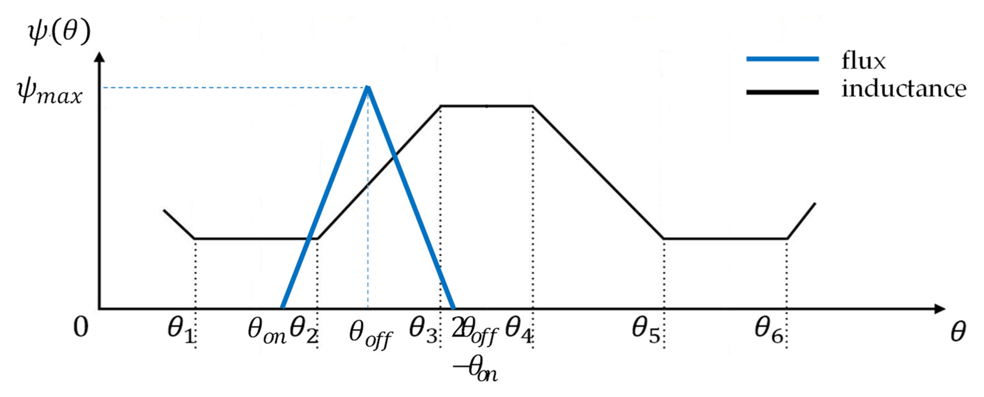
When θ = 2θoff − θon, the flux linkage decreases to zero. Through the above analysis, the variation curve of the flux linkage with the rotor angle can be obtained, as shown in Figure 2:
Then the functional expression of flux linkage is:
From the relationship between flux linkage and inductance, we can get:
Substituting Equation (8) into Equation (2):
Multiplying current on both sides of Equation (9) yields the following equation:
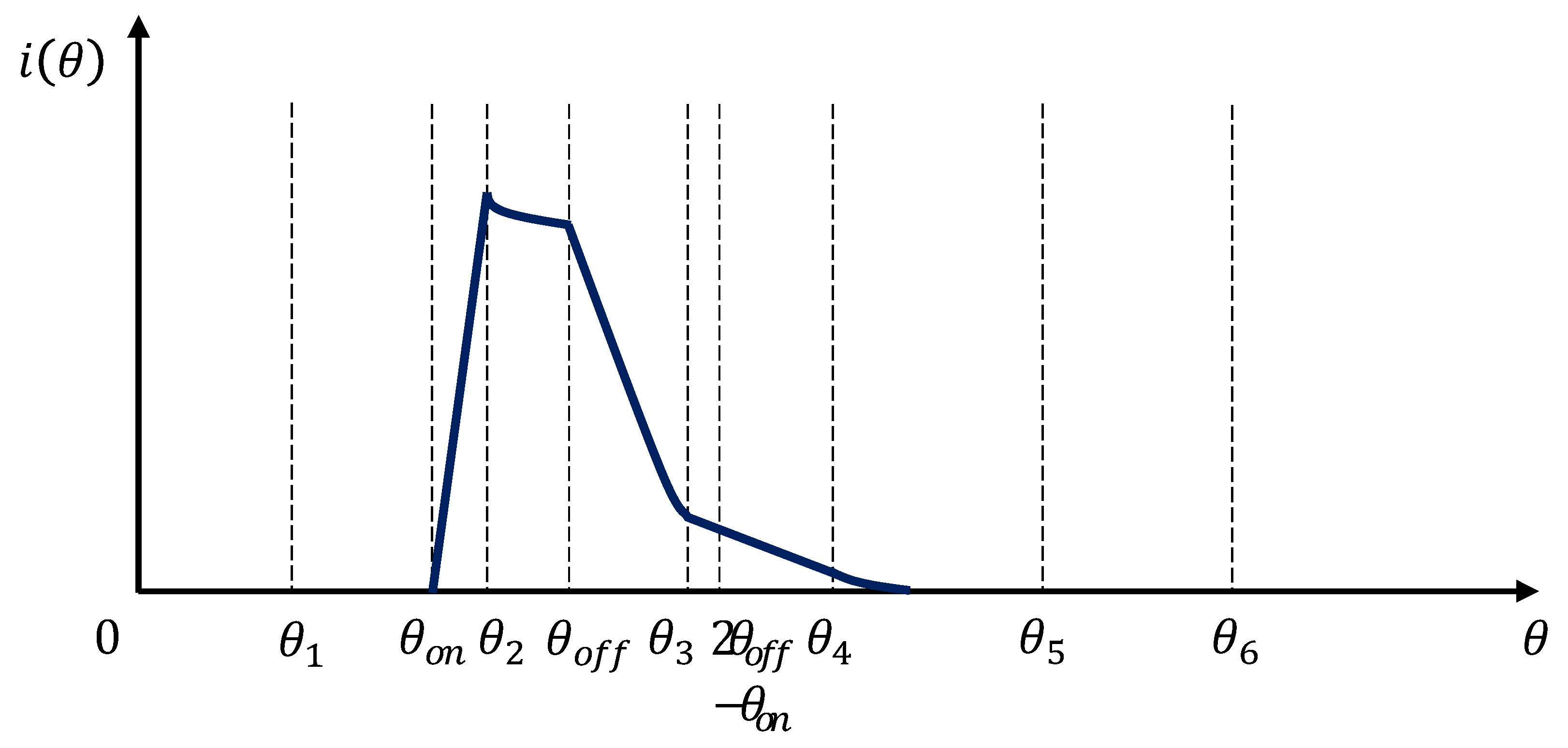
From Formula (10), it can be seen that part of the electrical energy input of the switched reluctance motor is converted into electromagnetic field energy storage, and the other part is converted into mechanical energy, which is the multiplication of phase current and electromotive force to provide power for the motor to rotate. Figure 3 shows the variation curve of the current with the rotor position in the next electrical cycle of the angle control strategy.
In the interval θ1 ≤ θ < θon, the motor phase has not been turned on, and no current flows through the phase winding. At this time, the phase current is:
In the interval θon ≤ θ < θ2, the voltage at both ends of the winding is Us, and the inductance is the minimum value Lmin. And after the winding is excited, both the current and the flux linkage start to rise. Hence, the phase current is obtained by Formula (9):
In the interval θoff ≤ θ < θ3, the voltage across the winding is -Us, and the phase current decreases rapidly. Substitute inductance Equation (7) into Equation (9) to get:
In the interval θ3 ≤ θ < 2θoff − θon, the inductance maintains the maximum value Lmax, and there are:
At this time, the current decreases linearly, and the slope is −Us/(ωLmax) = const, which is a constant.
In the interval of 2θoff − θon ≤ θ < θ5, the flux linkage is 0 and the current is also 0:
To sum up, in one cycle, the expression of current i(θ) is:
3. Influence of Switching Angle on Vibration
3.1. Current Harmoinc Model
The phase current of the SRM can be viewed as the Fourier series summation of several harmonic components. The torque ripple, vibration noise and operating efficiency of the SRM are mutually constrained, which can be established to quantitatively analyze the coupling relationship between different performance indicators. When the switched reluctance motor is running, considering the periodic characteristics of the switched reluctance motor, the current waveform can be expressed as a mathematical expression in the form of a Fourier series. This mathematical expression is called the current harmonic model, which is expressed as follows [25]:
where i0, ins and inc are the DC component, the n-th order sine component and the n-th order cosine component, respectively. N is the order of the cutoff frequency and θe is the rotor position angle (electrical angle).
3.2. Influence of Switching Angle on Current
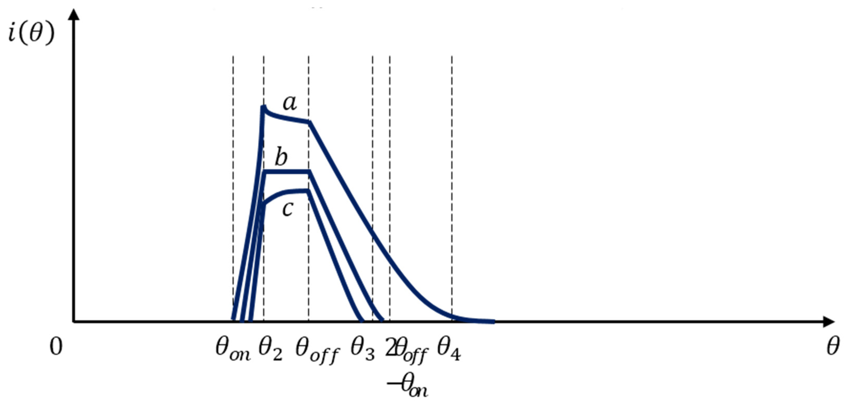
Switching angle control strategy achieves the purpose of controlling the operation of the motor by adjusting the turn-on and turn-off angles of each phase of the motor. As can be seen from the previous section, the inductance of the motor is at a minimum value before θ2 (the rotor angle at which the stator salient poles of the motor and the rotor groove begin to disengage), and the current increases linearly between the turn-on angles θon and θ2. Therefore, by changing the turn-on angle θon, the amplitude of the phase current in the inductance rising region is different, and the generated torque is also different. When the turn-off angle θoff of the motor is fixed, different turn-on angles will cause the current to have different waveforms, as shown in Figure 4.
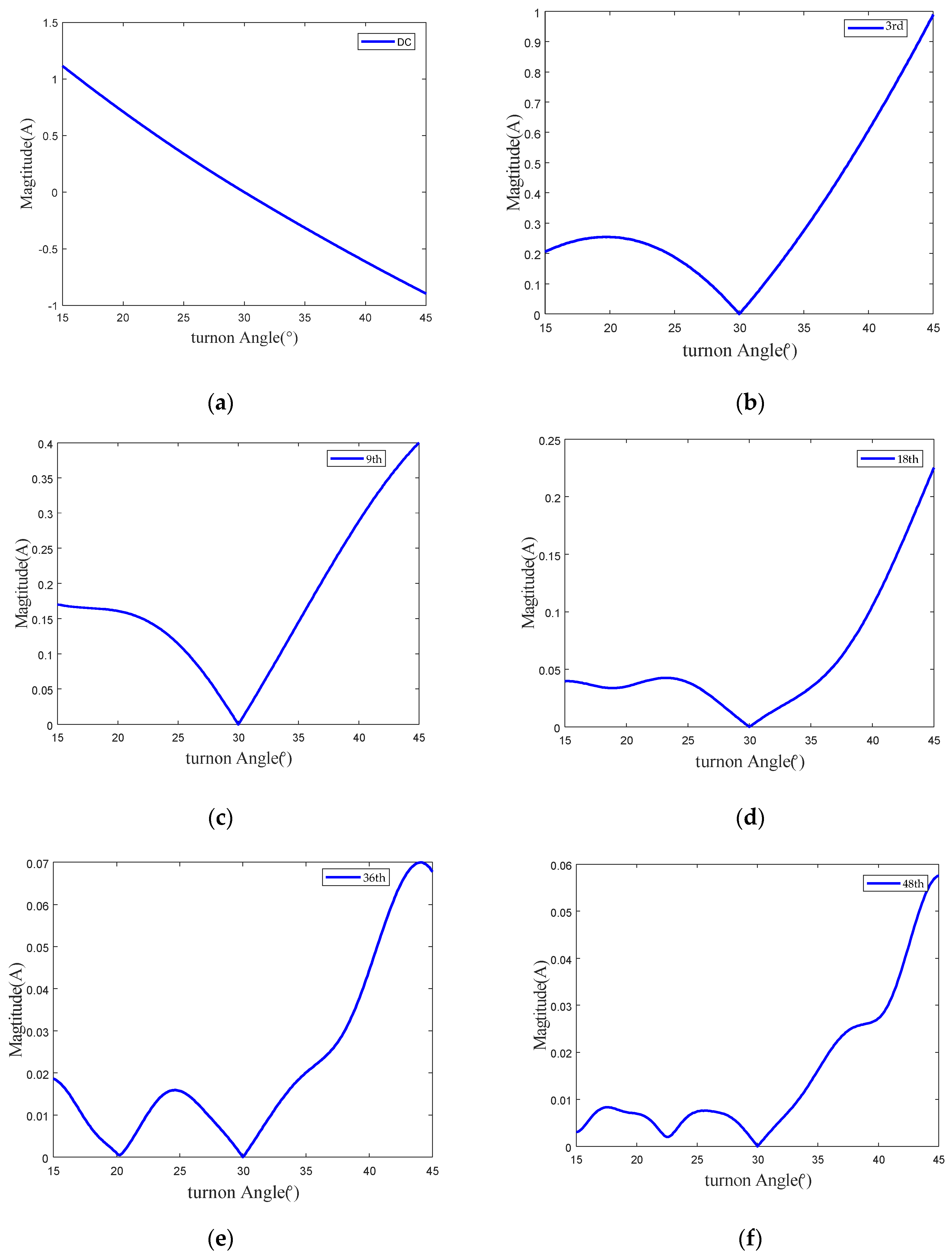
When the turn-on angle and di/dθ < 0, the current drops in the inductance rising region, as shown by curve a in Figure 4. This is because when the turn-on angle is too small, the current rises too fast, and when the motor turns to θ2, the current amplitude is too large, making the torque too large. At this time, the amplitude of the back EMF is greater than the bus voltage, and so the current decreases. When the turn-on angle and di/dθ = 0, the current amplitude remains unchanged, as shown by curve b in Figure 4. Since the back EMF is equal to the bus voltage, the current does not change. When the turn-on angle and di/dθ > 0, the phase current amplitude continues to increase when the motor turns to θ2, as shown by the curve c in the Figure 4. Due to the delay in the turn-on of the phase winding, the phase current is too small, and the rotating electromotive force is smaller than the bus voltage. The curve of the current harmonic components with the turn-on angle can be obtained by performing a Fourier transform on the current waveform. Figure 5 shows the current harmonic variation when the turn-off angle is fixed at 120° and the turn-on angle varies from 15° to 45°.
As can be seen from Figure 5, with the increase of harmonic order, the harmonic amplitude shows a decreasing trend. The DC component of the current waveform decreases with the increase of the turn-on angle, and other harmonic components first decrease and then increase with the change of the turn-on angle. There is a minimum value at a specific angle, such as the current harmonic amplitude, which has a minimum value at 30 centigrade as shown in Figure 5.
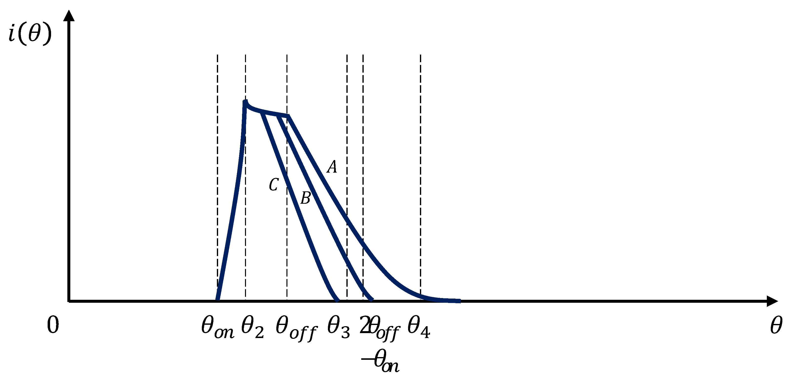
Similarly, if the turn-on angle of the motor is fixed, the change of turn-off angle will also cause the change of current waveform, as shown in Figure 6. It can be seen from the figure that the turn-off angle determines the position where the current is reduced to zero. In Formula (9), let i(θ) = 0, and get the zero point of the current θ0 = 2θoff − θon. When θ0 < θ3, i.e., θoff < (θ3 + θon)/2, the current has decreased to zero before the inductance increases to the maximum, as shown in curve C in Figure 6. When θ0 > θ3, i.e., θoff > (θ3 + θon)/2, the current decreases to zero in the maximum inductance area, as shown in curve B in Figure 6. When the turn-off angle continues to increase, the current is still not zero in the inductance drop area, as shown in curve A in Figure 6. It can be known from the electromagnetic torque characteristics that braking torque will be generated at this time.
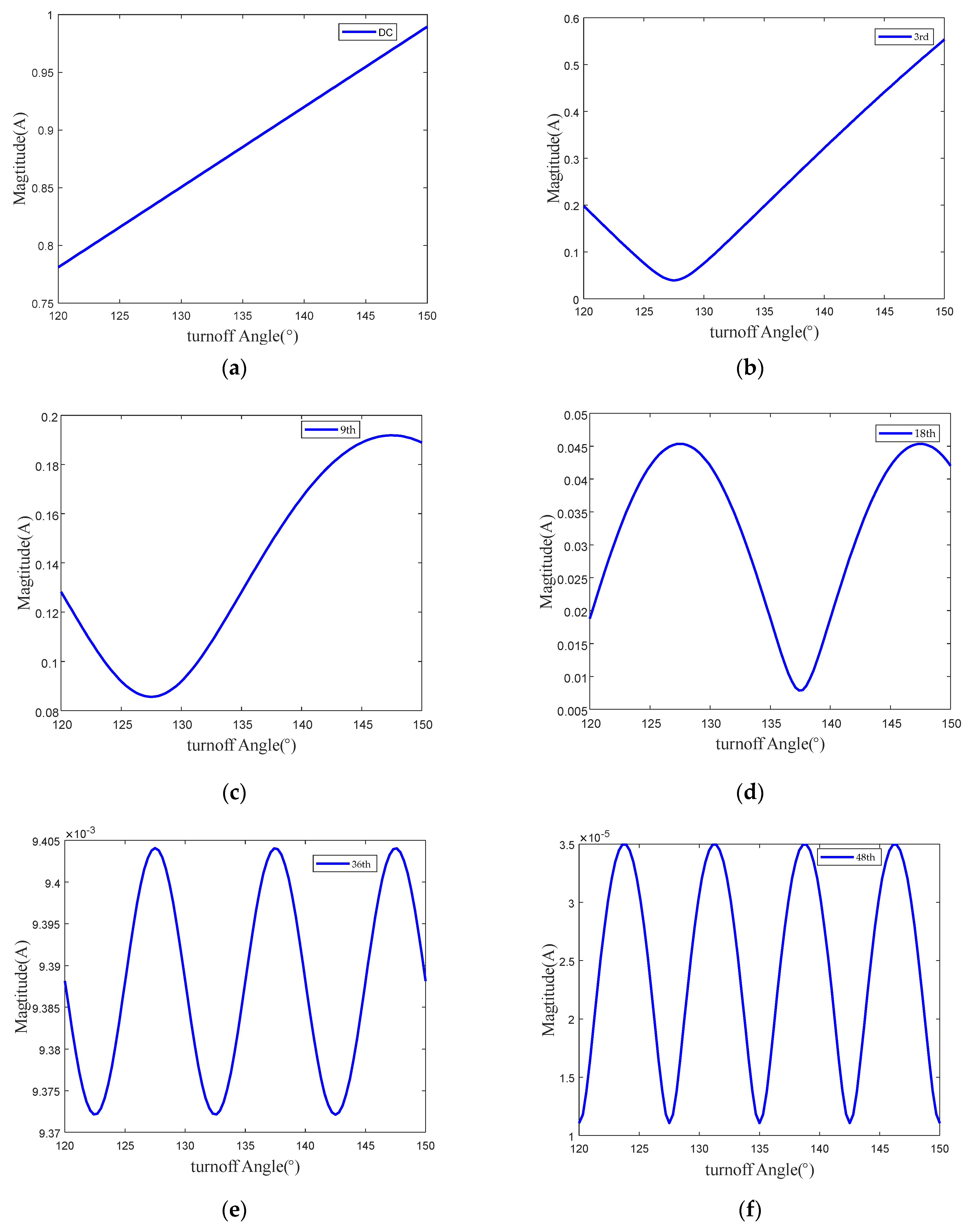
The curve of the current harmonic components with the turn-off angle can be obtained by Fourier transform of the current waveform at different turn-off angles. Figure 7 shows the current harmonic variation rule when the reference current is 5A, the turn-on angle is fixed at 15°, and the turn-off angle varies from 120° to 150°. As can be seen from the figure, as the harmonic order increases, the harmonic amplitude shows a decreasing trend. From the variation trend of current harmonics of each order, it can be seen that the influence of the turn-off angle on current harmonics has obvious regularity. With the increase of the harmonic order, the current harmonic amplitude gradually presents the characteristics of periodic oscillation with the change of the turn-off angle, and with the increase of the harmonic order, the oscillation period gradually shortens. It can be read from the figure that the oscillation period of the 18th order is 20 degrees, and the oscillation periods of the 36th and 48th order of current harmonics are 10 degrees and 5 degrees, respectively. After comparing and analyzing the harmonic amplitudes and their vibration periods of other orders, it is found that the oscillation period of the current harmonic amplitudes is related to the current harmonic orders, and the following relationship is approximately satisfied between them:
Tk is the oscillation period of the k-th order current harmonics changing with the turn-off angle. For low-order harmonics, due to the long oscillation period, the oscillation period cannot be observed in the limited range of off-angle variation.
In the actual operation of the switched reluctance motor, for the same working conditions, there are various combinations of switching angles to achieve the speed regulation and torque control requirements. Under the angle control strategy, different switching angle combinations will generate different current waveforms, which will affect the performance parameters of the motor, such as vibration, torque ripple, and energy efficiency.
3.3. Influence of Switching Angle on Vibration
When the switched reluctance motor is running, the frequency of the excitation current and its harmonic components is determined by the rotational speed and the number of rotor poles, and the frequency of the n-th order current harmonic is:
where, fe is the excitation current harmonic frequency, ω is the motor speed, Nr is the number of rotor poles and k is the current harmonic order. Cai et al. showed that when the harmonic frequency of the current is consistent with the natural frequency of the motor, it will cause the motor to vibrate. The two-step commutation method is one of the control strategies to reduce the vibration of switched reluctance motors. In the two-step commutation method, the upper bridge switch of the power amplifier is first turned off to induce free damped oscillation, and the oscillation frequency is equal to the characteristic frequency of the main mode shape. Then, after half a cycle, the lower bridge switch is turned off, causing another oscillation with the same amplitude and a phase shift of 180°. After the two oscillations are superimposed on each other, the vibration at the characteristic frequency can be significantly reduced. This method shows that a specific shift in the radial force harmonic spectrum can be produced by adjusting the turn-off angle. Therefore, the radial force spectrum can be shifted by adjusting the turn-off angle. When the switched reluctance motor is commutated, the current harmonic component that is the same as the natural frequency of the motor can be minimized, which is helpful for vibration suppression. In order for the k-th current harmonic to have a phase offset of 180°, the interval between the two turn-off angles is equal to half the excitation period:
The spacing angle (electrical angle) between the two off angles is
Substituting Equation (21) into Equation (20), we get
Tk represents the period in which the current harmonic amplitude changes with the turn-off angle. When the turn-off angle moves by 2θi, the k-th order harmonic value of the current also changes periodically. This conclusion is consistent with the conclusion drawn in previous section when the turn-on angle is constant and the turn-off angle changes.
The vibration of a switched reluctance motor can be represented as a linear superposition of a finite number of single-degree-of-freedom systems in modal coordinates. In modal coordinates, the relationship between radial force and its induced vibration can be described in the transfer function
is the transmission impedance of radial force at a specified frequency in mode n, which can be identified analytically or experimentally. For the n-th order radial force harmonic, the corresponding vibration in the m-th order mode is:
As shown in Equations (3)–(22), the frequency of the higher harmonics of the excitation current is an integer multiple of the fundamental frequency, and the integer k is the harmonic order. Therefore, the critical harmonic depends on the rotational speed, which causes differences in vibration characteristics when the speed changes. Vibration can be reduced by reducing the harmonic components of radial forces that coincide with the eigen frequency of the body. According to the vibration test results of the switched reluctance motor, the vibration of the low-order mode is more obvious, and the low-order characteristic frequencies of the motor used are 634 Hz and 1220 Hz, corresponding to the first-order and second-order vibration modes, respectively. To reduce vibration, it is necessary to avoid excitation harmonic frequencies that coincide with natural frequencies. When the two are consistent, there is the following formula:
where fn is the n-order natural frequency of the motor. For a 3-phase motor with a 12-8 structure, the harmonic order k is usually limited to three or a multiple of three. When n is 2, the corresponding harmonic order and rotational speed value under the second-order vibration mode are considered as shown in Table 1. It can be seen from the table that the current harmonic order to be analyzed is also different under different rotational speeds. For example, under the premise of a certain load torque, the influence law of the change of the turn-on angle and the turn-off angle on the vibration of the switched reluctance motor at 2034 RPM can be obtained by analyzing the change law of its third-order current harmonic component under different turn-on angles and turn-off angles. It can be seen from the previous section that when the turn-off angle is fixed, with the change of the turn-on angle, there is a minimum value for each order harmonic component of the current, except for the DC component, and the minimum value is not a boundary value. When the turn-on angle is fixed, with the change of the turn-on angle, there is a minimum value for each order harmonic component of the current, except for the DC component, and the minimum value is also not at the boundary. Therefore, for different switching angle combinations, there must be an amplitude that makes the harmonic components of any order current, with the smallest set of switching angles, at which the vibration is minimal.
4. Experimental Verification and Analysis
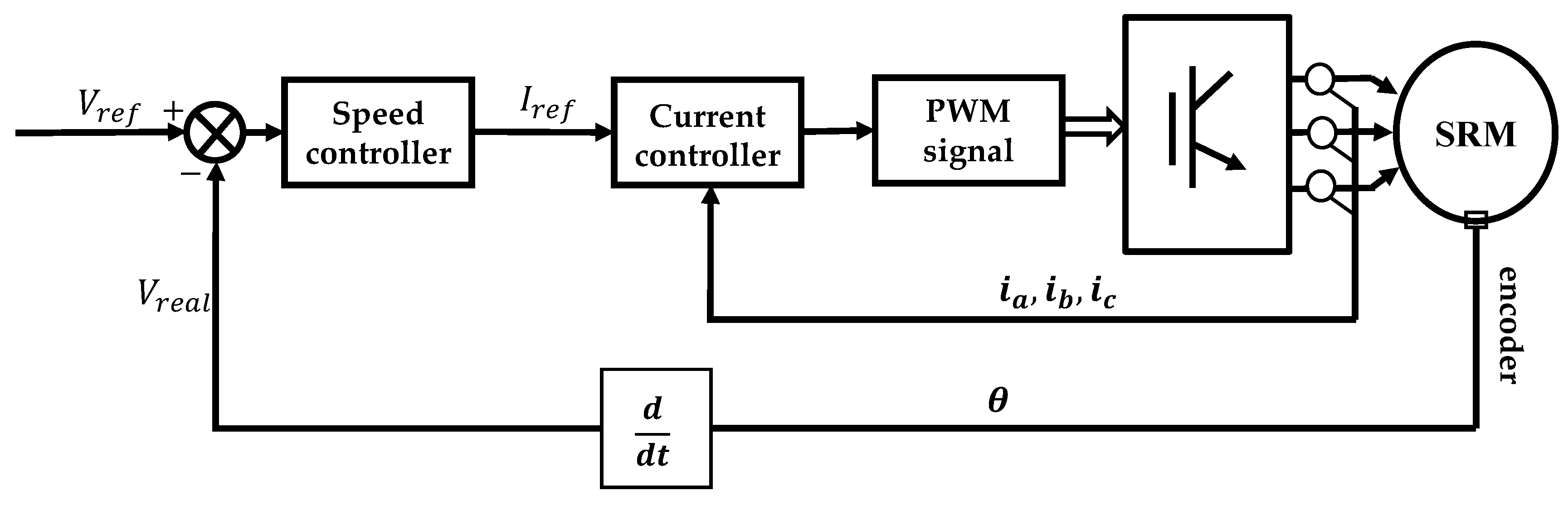
This experiment is tested on a 1.5 KW, 12-8 switched reluctance motor test bench. The control system scheme is shown in Figure 8. The load is adjusted by adjusting the loading current of the eddy current brake.
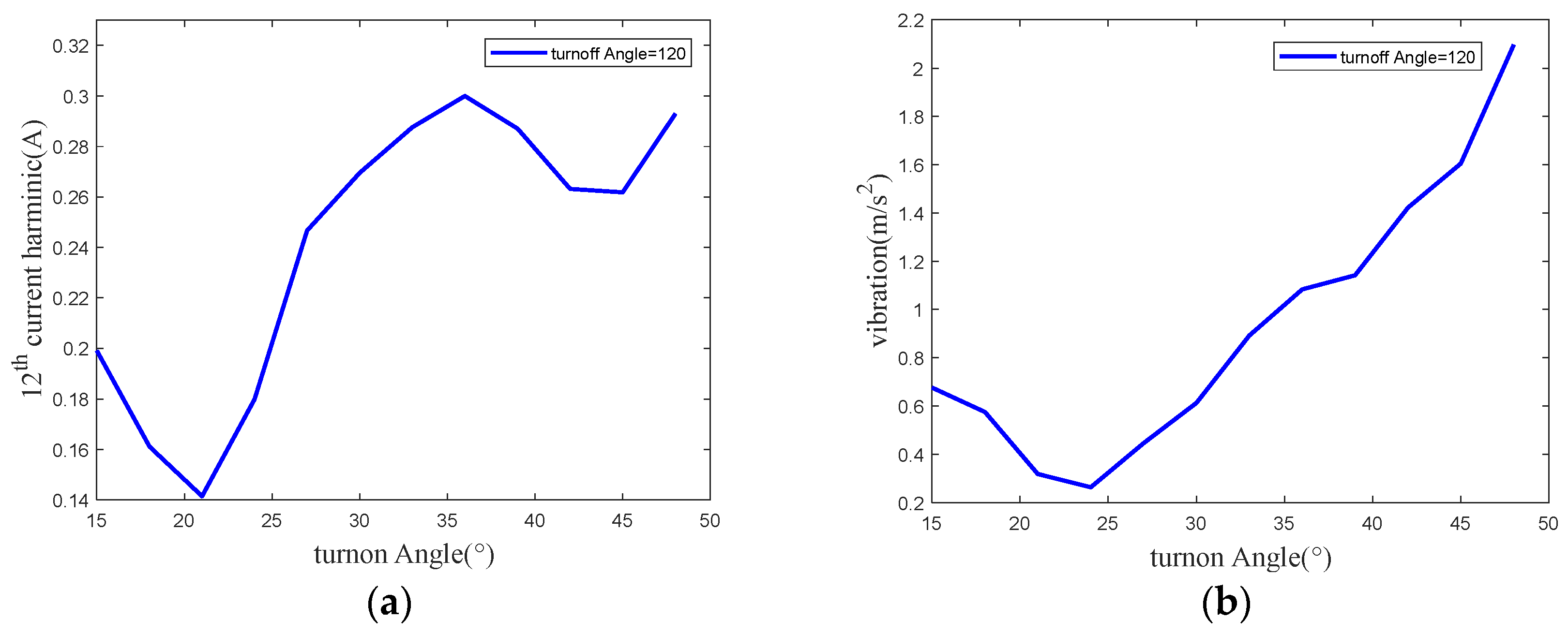
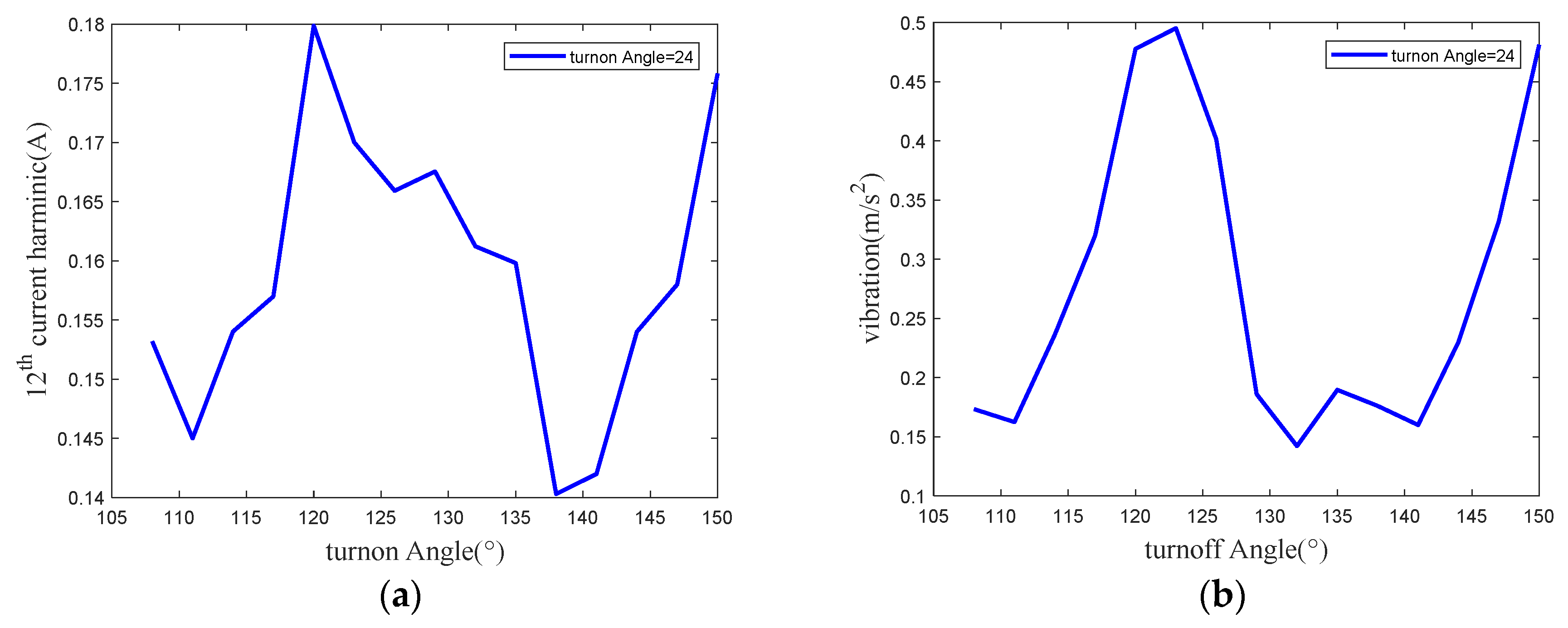
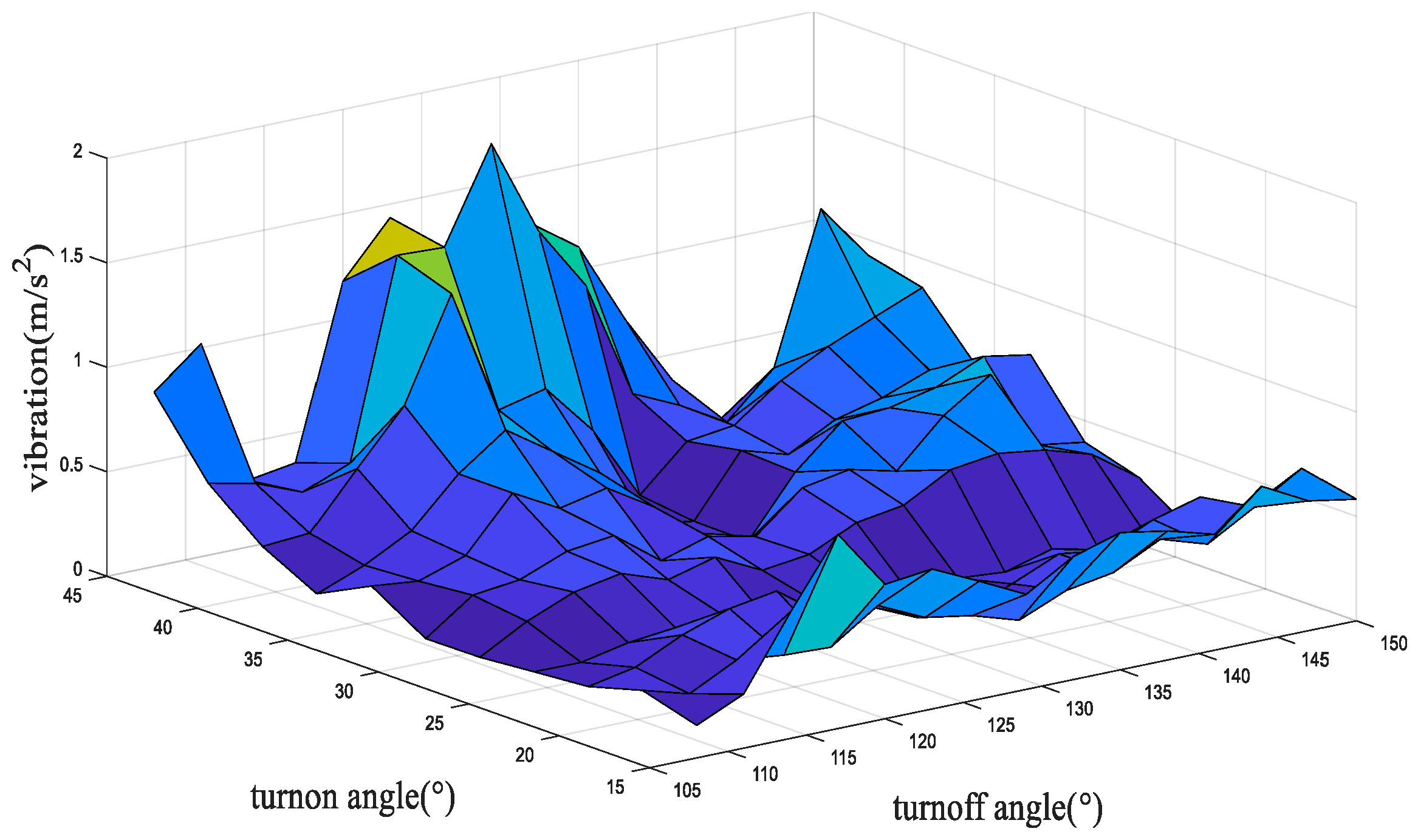
Figure 9 shows the variation curve of the 12th order current harmonic component and the second-order vibration amplitude with the turn-on angle when the turn-off angle is constant, at 120°. Figure 10 shows the variation curve of the 12th order current harmonic component and the second order vibration amplitude with the turn-off angle when the turn-on angle is unchanged at 24°. Figure 11 shows the variation curve of the second-order vibration amplitude under the condition that the opening angle is in the range of 15° to 45° and the closing angle is in the range of 120° to 150°.
It can be seen from Figure 9 that the current harmonic components and vibrations change periodically with the change of the turn-on angle. When the turn-on angle is 21° and 24°, the 12th-order current harmonic components and vibration amplitudes obtain the minimum value, respectively. As can be seen from Figure 10, with the change of the turn-off angle, the harmonic components and vibrations of the 12th-order current show an approximate periodic oscillation trend, with the oscillation period of 30°. When the turn-off angle is around 138°, the 12th-order current harmonic and vibration obtain the minimum value.
Through Figure 9, Figure 10 and Figure 11, the conclusions of previous sections can be verified. For the switched reluctance motor regulated by the strategy of the switching angle control method, when the turn-off angle remains unchanged, and with the increase of the turn-on angle, the current harmonic components increase first and then decrease. When the turn-on angle remains unchanged, with the increase of the turn-off angle, the current harmonic components show a periodic oscillation trend, and the oscillation period is related to the current harmonic order. For a specific speed, the current harmonic order that plays a leading role in the second-order vibration can be deduced according to Formula (25). By analyzing this harmonic order, the variation law of vibration with the switching angle can be obtained.
5. Conclusions
This manuscript focuses on the influence of the change of turn-on angle and turn-off angle on the vibration of an SRM under the SAC strategy. The phase current of the SRM is presented in the form of a harmonic model, which is the Fourier series summation of several harmonic components. The current waveforms at various turn-on angles and turn-off angles are analyzed by Fourier transform. The analysis result shows that when the turn-off angle is constant, the current harmonic first decreases and then increases with the increase of the turn-on angle. In addition, when the turn-on angle is constant, the current harmonic shows the tendency of periodic oscillation with the variation of the turn-off angle, and the oscillation period is related to the harmonic order. To a certain speed for an SRM, the current harmonic order that plays a leading role in the second-order vibration can be deduced. By analyzing the value of this harmonic order, the variation law of vibration with the switching angle can be obtained. The effectiveness of the proposed method was verified on a 12/8 poles, 1.5 KW SRM drive system test bench. The result shows that when the SRM is rotating at the speed of 763 rpm, the variation law of vibration with the turn-on angle and turn-off angle can be reflected by its 12th order harmonic component. It is seen that current harmonic components and vibrations change periodically with the change of the turn-on angle. When the turn-on angle is 21° and 24°, the 12th order current harmonic components and vibration amplitudes obtain the minimum value, respectively. Additionally, with the change of the turn-off angle, the harmonic components and vibrations of the 12th order current show an approximate periodic oscillation tendency, with the oscillation period of 30°. When the turn-off angle is around 138°, the 12th-order current harmonic and vibration obtain the minimum value. The combination of switching angles that minimizes the certain current harmonic component also minimizes vibration, which provides a new perspective on vibration suppression of SRMs.
Author Contributions
Conceptualization, X.L. and C.Z.; methodology, X.L.; software, X.L.; validation, X.L., C.Z. and L.Y.; formal analysis, X.L.; investigation, X.L.; resources, X.L.; data curation, X.L.; writing—original draft preparation, X.L.; writing—review and editing, X.L.; visualization, X.L.; supervision, J.Z.; project administration, J.Z.; funding acquisition, J.Z. All authors have read and agreed to the published version of the manuscript.
Funding
This research was funded by National Natural Science Foundation of China (grant number 51935007 and 52175512) and the Science and Technology Committee of Shanghai (grant number 19142203600).
Institutional Review Board Statement
Not applicable.
Informed Consent Statement
Not applicable.
Data Availability Statement
The study did not report any data.
Conflicts of Interest
The authors declare no conflict of interest.
References
- Fang, G.; Scalcon, F.P.; Xiao, D.; Vieira, R.P.; Grundling, H.A.; Emadi, A. Advanced Control of Switched Reluctance Motors (SRMs): A Review on Current Regulation, Torque Control and Vibration Suppression. IEEE Open J. Ind. Electron. Soc. 2021, 2, 280–301. [Google Scholar] [CrossRef]
- Takeno, M.; Chiba, A.; Hoshi, N.; Ogasawara, S.; Takemoto, M.; Rahman, M.A. Test Results and Torque Improvement of the 50-kW Switched Reluctance Motor Designed for Hybrid Electric Vehicles. IEEE Trans. Ind. Appl. 2012, 48, 1327–1334. [Google Scholar] [CrossRef]
- Ling, X.; Tao, J.; Li, B.; Qin, C.; Liu, C. A Multi-Physics Modeling-Based Vibration Prediction Method for Switched Reluctance Motors. Appl. Sci. 2019, 9, 4544. [Google Scholar] [CrossRef] [Green Version]
- Bostanci, E.; Moallem, M.; Parsapour, A.; Fahimi, B. Opportunities and Challenges of Switched Reluctance Motor Drives for Electric Propulsion: A Comparative Study. IEEE Trans. Transp. Electrif. 2017, 3, 58–75. [Google Scholar] [CrossRef]
- Qin, C.; Shi, G.; Tao, J.; Yu, H.; Jin, Y.; Xiao, D.; Zhang, Z.; Liu, C. An adaptive hierarchical decomposition-based method for multi-step cutterhead torque forecast of shield machine. Mech. Syst. Signal Process. 2022, 175, 109148. [Google Scholar] [CrossRef]
- Yang, H.-Y.; Lim, Y.-C.; Kim, H.-C. Acoustic Noise/Vibration Reduction of a Single-Phase SRM Using Skewed Stator and Rotor. IEEE Trans. Ind. Electron. 2012, 60, 4292–4300. [Google Scholar] [CrossRef]
- Gan, C.; Wu, J.; Shen, M.; Yang, S.; Hu, Y.; Cao, W. Investigation of Skewing Effects on the Vibration Reduction of Three-Phase Switched Reluctance Motors. IEEE Trans. Magn. 2015, 51, 1–9. [Google Scholar] [CrossRef] [Green Version]
- Isfahani, A.H.; Fahimi, B. Comparison of Mechanical Vibration Between a Double-Stator Switched Reluctance Machine and a Conventional Switched Reluctance Machine. IEEE Trans. Magn. 2014, 50, 293–296. [Google Scholar] [CrossRef]
- Widmer, J.D.; Mecrow, B.C. Optimized Segmental Rotor Switched Reluctance Machines with a Greater Number of Rotor Segments Than Stator Slots. IEEE Trans. Ind. Appl. 2013, 49, 1491–1498. [Google Scholar] [CrossRef]
- Kurihara, N.; Bayless, J.; Sugimoto, H.; Chiba, A. Noise Reduction of Switched Reluctance Motor with High Number of Poles by Novel Simplified Current Waveform at Low Speed and Low Torque Region. IEEE Trans. Ind. Appl. 2016, 52, 3013–3021. [Google Scholar] [CrossRef]
- Chai, J.; Lin, Y.; Liaw, C. Comparative study of switching controls in vibration and acoustic noise reductions for switched reluctance motor. IEE Proc.-Electr. Power Appl. 2006, 153, 348–360. [Google Scholar] [CrossRef] [Green Version]
- Zhu, Z.Q.; Liu, X.; Pan, Z. Analytical Model for Predicting Maximum Reduction Levels of Vibration and Noise in Switched Reluctance Machine by Active Vibration Cancellation. IEEE Trans. Energy Convers. 2010, 26, 36–45. [Google Scholar] [CrossRef]
- Takiguchi, M.; Sugimoto, H.; Kurihara, N.; Chiba, A. Acoustic Noise and Vibration Reduction of SRM by Elimination of Third Harmonic Component in Sum of Radial Forces. IEEE Trans. Energy Convers. 2015, 30, 883–891. [Google Scholar] [CrossRef]
- Shen, S.; Wang, H.; Feng, Y.; Li, M.; Zhong, Y. Predictive Current Control for Switched Reluctance Motor Based on Local Linear Phase Voltage Model. Appl. Sci. 2022, 12, 1688. [Google Scholar] [CrossRef]
- Tarvirdilu-Asl, R.; Nalakath, S.; Bilgin, B.; Emadi, A. A Finite Control Set Model Predictive Torque Control for Switched Reluctance Motor Drives with Adaptive Turn-off Angle. In Proceedings of the IECON 2019—45th Annual Conference of the IEEE Industrial Electronics Society, Lisbon, Portugal, 14–17 October 2019. [Google Scholar] [CrossRef]
- Qin, C.; Xiao, D.; Tao, J.; Yu, H.; Jin, Y.; Sun, Y.; Liu, C. Concentrated velocity synchronous linear chirplet transform with application to robotic drilling chatter monitoring. Measurement 2022, 194, 111090. [Google Scholar] [CrossRef]
- Reis, M.R.D.C.; de Araujo, W.R.H.; Gomes, V.M.; Silva, F.D.S.E.; Ganzaroli, C.A.; Gomes, F.A.; Wainer, G.A.; Calixto, W.P. Optimized techniques for driving and control of the switched reluctance motor to improve efficiency. Control Eng. Pract. 2019, 90, 1–18. [Google Scholar] [CrossRef]
- Mademlis, C.; Kioskeridis, I. Performance optimization in switched reluctance motor drives with online commutation angle control. IEEE Trans. Energy Convers. 2003, 18, 448–457. [Google Scholar] [CrossRef]
- Husain, T.; Elrayyah, A.; Sozer, Y.; Husain, I. Unified Control for Switched Reluctance Motors for Wide Speed Operation. IEEE Trans. Ind. Electron. 2018, 66, 3401–3411. [Google Scholar] [CrossRef]
- Guo, X.; Zhong, R.; Zhang, M.-S.; Ding, D.-S.; Sun, W. Resonance Reduction by Optimal Switch Angle Selection in Switched Reluctance Motor. IEEE Trans. Ind. Electron. 2019, 67, 1867–1877. [Google Scholar] [CrossRef]
- Bayless, J.; Kurihara, N.; Sugimoto, H.; Chiba, A. Acoustic Noise Reduction of Switched Reluctance Motor with Reduced RMS Current and Enhanced Efficiency. IEEE Trans. Energy Convers. 2015, 31, 627–636. [Google Scholar] [CrossRef]
- Desai, P.C.; Krishnamurthy, M.; Schofield, N.; Emadi, A. Novel Switched Reluctance Machine Configuration with Higher Number of Rotor Poles Than Stator Poles: Concept to Implementation. IEEE Trans. Ind. Electron. 2009, 57, 649–659. [Google Scholar] [CrossRef]
- Xu, Y.; Zhong, R.; Chen, L.; Lu, S. Analytical method to optimise turn-on angle and turn-off angle for switched reluctance motor drives. IET Electr. Power Appl. 2012, 6, 593–603. [Google Scholar] [CrossRef]
- Pereira, M.F.S.; Mamede, A.; Araújo, R.E. Switched Reluctance Motor Drives: Fundamental Control Methods; IntechOpen: London, UK, 2020. [Google Scholar] [CrossRef]
- Li, B.; Dong, Z.; Huang, Y.; Liu, C. Analysis on accuracy of rotor-locked transient-response-based vibration model for switched reluctance machines. IET Electr. Power Appl. 2022, 16, 616–633. [Google Scholar] [CrossRef]
Figure 1.
(a) The simplified structure of a 12-8 SRM (b) Inductance curve of linear model.

Figure 2.
Flux linkage curve of linear model.

Figure 3.
Current curve of one electric period.

Figure 4.
Current curves with constant turn-off angles and different turn-on angles.

Figure 5.
Influence of turn-on angle to current harmonic magnitude (a) DC (b) 3rd order (c) 9th order (d) 18th order (e) 36th order (f) 48th order.
Figure 5.
Influence of turn-on angle to current harmonic magnitude (a) DC (b) 3rd order (c) 9th order (d) 18th order (e) 36th order (f) 48th order.

Figure 6.
Current curves under constant turn-on angles and different turn-off angles.

Figure 7.
Influence of turn-off angle to current harmonic magnitude (a) DC (b) 3rd order (c) 9th order (d) 18th order (e) 36th order (f) 48th order.
Figure 7.
Influence of turn-off angle to current harmonic magnitude (a) DC (b) 3rd order (c) 9th order (d) 18th order (e) 36th order (f) 48th order.

Figure 8.
Scheme for speed control system of SRM based on angle control strategy.

Figure 9.
The 12th current harmonic and the 2nd vibration value under different turn-on angles (15–48°) (a) Variation curve of 12th order current harmonic with turn-on angle (b) Variation curve of second-order vibration amplitude with turn-on angle.
Figure 9.
The 12th current harmonic and the 2nd vibration value under different turn-on angles (15–48°) (a) Variation curve of 12th order current harmonic with turn-on angle (b) Variation curve of second-order vibration amplitude with turn-on angle.

Figure 10.
The 12th current harmonic and the 2nd vibration value under different turn-off angles (108–150°) and fixed turn-on angle (24°) (a) Variation curve of 12th order current harmonic with turn-on angle (b) Variation curve of second-order vibration amplitude with turn-on angle.
Figure 10.
The 12th current harmonic and the 2nd vibration value under different turn-off angles (108–150°) and fixed turn-on angle (24°) (a) Variation curve of 12th order current harmonic with turn-on angle (b) Variation curve of second-order vibration amplitude with turn-on angle.

Figure 11.
The 2nd vibration under different turn-on (15–45°) and turn-off (125–145°) angles.


Table 1.
Speed of SRM when the frequency of current harmonics coincide with the 2nd order natural.
| Harmonic Order, k = 3 m | Speed |
|---|---|
| m = 1, 3rd | 2034 r/min |
| m = 2, 6th | 1017 r/min |
| m = 3, 9th | 915 r/min |
| m = 4, 12th | 763 r/min |
| m = 5, 15th | 610 r/min |
| m = 6, 18th | 508 r/min |
Publisher’s Note: MDPI stays neutral with regard to jurisdictional claims in published maps and institutional affiliations. |
© 2022 by the authors. Licensee MDPI, Basel, Switzerland. This article is an open access article distributed under the terms and conditions of the Creative Commons Attribution (CC BY) license (https://creativecommons.org/licenses/by/4.0/).
Share and Cite
MDPI and ACS Style
Ling, X.; Zhou, C.; Yang, L.; Zhang, J. Research on Influence of Switching Angle on the Vibration of Switched Reluctance Motor. Appl. Sci. 2022, 12, 4793. https://0-doi-org.brum.beds.ac.uk/10.3390/app12094793
AMA Style
Ling X, Zhou C, Yang L, Zhang J. Research on Influence of Switching Angle on the Vibration of Switched Reluctance Motor. Applied Sciences. 2022; 12(9):4793. https://0-doi-org.brum.beds.ac.uk/10.3390/app12094793
Chicago/Turabian StyleLing, Xiao, Chenhao Zhou, Lianqiao Yang, and Jianhua Zhang. 2022. "Research on Influence of Switching Angle on the Vibration of Switched Reluctance Motor" Applied Sciences 12, no. 9: 4793. https://0-doi-org.brum.beds.ac.uk/10.3390/app12094793
Note that from the first issue of 2016, this journal uses article numbers instead of page numbers. See further details here.