Compact Left-Handed Meta-Atom for S-, C- and Ku-Band Application


1
Space Science Centre (ANGKASA), Universiti Kebangsaan Malaysia, 43600 UKM Bangi, Selangor, Malaysia
2
Department of Electrical, Electronic and Systems Engineering, Universiti Kebangsan Malaysia, 43600 UKM Bangi, Selangor, Malaysia
*
Authors to whom correspondence should be addressed.
Appl. Sci. 2017, 7(10), 1071; https://0-doi-org.brum.beds.ac.uk/10.3390/app7101071
Submission received: 10 August 2017
/
Accepted: 10 October 2017
/
Published: 23 October 2017
Abstract
:A new compact left-handed meta-atom for S-, C- and Ku-band applications is presented in this paper. The proposed structure provides a wide bandwidth and exhibits left-handed characteristics at 0°, 90°, 180° and 270° (xy-axes) rotations. Besides, the left-handed characteristics and wide bandwidth of 1 × 2, 2 × 2, 3 × 3 and 4 × 4 arrays are also investigated at the above-mentioned rotation angles. In this study, the meta-atom is designed by creating splits at the outer and inner square-shaped ring resonators, and a metal arm is placed at the middle of the inner ring resonator. The arm is also connected to the upper and lower portions of the inner ring resonator, and later, the design appears as an I-shaped split ring resonator. The commercially available, finite integration technique (FIT)-based electromagnetic simulator CST Microwave Studio is used for design and simulation purposes. The measured data comply well with the simulated data of the unit cell for 1 × 2, 2 × 2, 3 × 3 and 4 × 4 arrays at every rotation angle. Owing to the effective medium ratio (EMR) of 8.50 at 0° and 180° rotations, the proposed meta-atom structure is compact in size. Moreover, due to the quality factor of 82, the designed meta-atom is flexible for high-performance antenna, filter and sensor applications. Therefore, the meta-atom integrated antenna shows multi frequency bands with the highest peak gain of 5 dBi, which is used as the long distance radio communication frequency.
1. Introduction
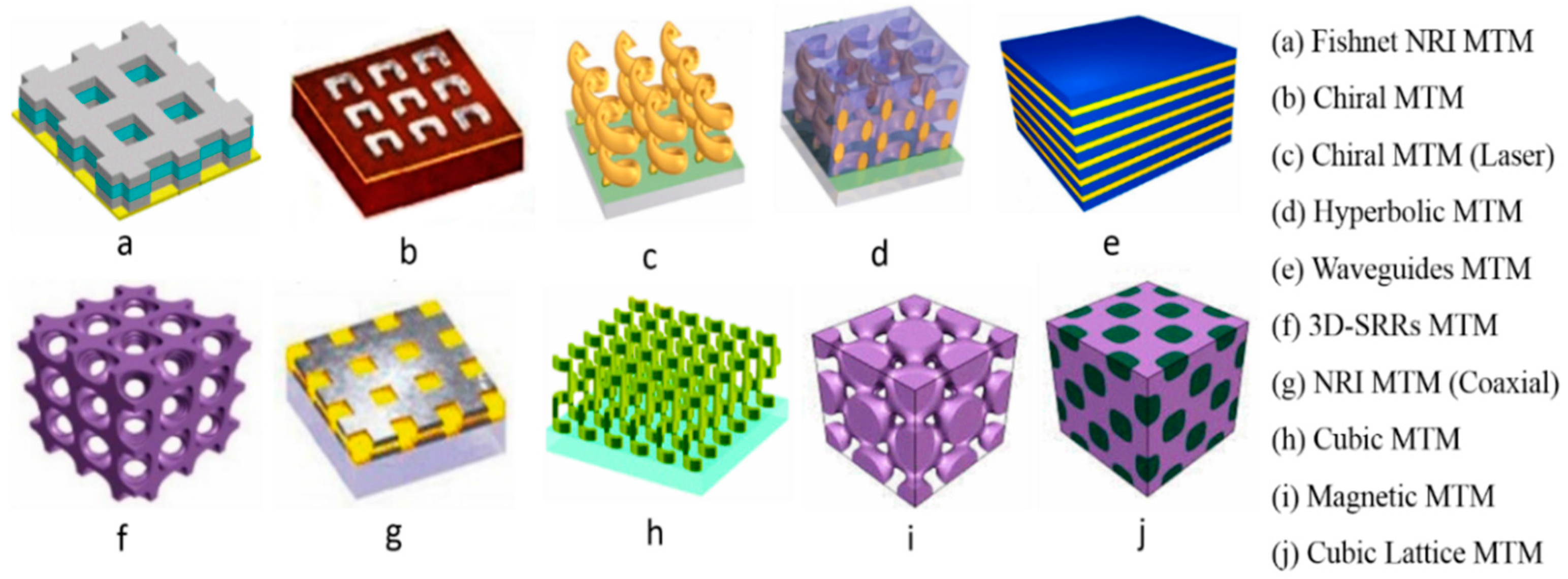
Electromagnetic meta-atoms are composed of artificial atoms, whose electric and magnetic response could be flexibly tailored to meet desired exotic EM properties. Benefiting from these novel properties, meta-atoms have produced many exotic effects in several applications, such as negative permeability, sub-wavelength imaging super-lens, electromagnetic absorbers [1], negative refraction [2], filter design [3], antenna performance enhancing, SAR reduction [4] and invisible cloaking [5]. The development of the meta-atoms utilizes the intrinsic loss of the system, with the help of structural design, to obtain a wide bandwidth or sharp resonance at a certain frequency. Material that exhibits either negative permittivity or negative permeability is called a single-negative meta-atom. When the values of permittivity and permeability are near zero over a specific frequency range, the material is specified as a near-zero refractive index meta-atom. Moreover, a material exhibiting negative permeability and negative permittivity simultaneously can be characterized as a double-negative or left-handed meta-atom. Although negative permittivity can be found in a few metals, negative penetrability is hard to discover. Therefore, the presence of both negative permeability and permittivity is exceptionally hard to acquire as the characteristic for left-handed materials. Recently, various composites based on metallic and dielectric structures that act as left-handed meta-atoms have been developed (Figure 1) [6,7,8,9,10,11,12].
In 1968, Veselago first discussed the negative index material. He demonstrated that a negative index material refraction would occur at negative angles, energy would flow in a direction opposite to the direction of the phase velocity and the Doppler effect would be reversed at a certain frequency [13]. In 1996, Pendry et al. projected their summary of a thin wire configuration, which exhibited a negative permittivity (ε), and in 1999, they presented the split ring resonator with a negative permeability (μ) [14]. Owing to the absence of such properties in natural materials, the topic was not particularly interesting to researchers until Smith and his colleagues invented the first successful metamaterial in the laboratory. In 2000, Smith et al. exhibited a material that displayed negative permittivity and permeability at the same time with unusual natural properties [15]. In the last few years, multi-band meta-atom arrays at different rotation angles with a compact size, left-handed properties and a wide bandwidth have become a promising research field for specialists because very few studies are concentrated on this sector. In 2017, Hasan et al. suggested that a tri-band metamaterial absorber was developed by the square shape resonators with a circular ring in the middle of the square resonators. The designed metamaterial absorber illustrates a 4.71 GHz-wide bandwidth and applicable for tri- (C-, X- and Ku-) band applications. The effective medium ratio was 5.83, and the absorptions were respectively, 82%, 67% and 93% [1]. In 2013, Mallik et al. introduced a rectangular “U-shaped” left-handed metamaterial for several orthogonal array structure, and the effective medium ratio was 1.99 [16]. In 2014, Islam et al. proposed a 30 × 30-mm2 “H-shaped” metamaterial for multi-band operations, and the resonance frequencies were found at S-, C-, X- and Ku-bands. In addition, the H-shaped structure exhibited double-negative characteristics, but the effective medium ratio was 3.64. However, the sensitivity of these metamaterial was only 13 [17]. In 2015, Purushothaman et al. explained a “ring-shaped” metamaterial structure applicable as a filter in waveguides. Moreover, the effect on the resonance of the parameters, such as the ring width, inner and outer ring gap, splitting of the ring, substrate material thickness and orientation of the substrate material, was investigated in their paper [3]. In 2015, Hossain et al. introduced a two “G-shaped” double negative (DNG) metamaterial, where the unit cell and arrays are different in size, and the metamaterial was suitable for S- and C-band applications. The dimensions of the presented metamaterial structure were 12 × 12 mm2 [18]. In 2015, Armghan et al. proposed a metamaterial based on split ring resonators to produce a negative refractive index at terahertz frequencies. The 2200 × 2200-nm2 structure exhibited left-handed characteristics at approximately 9.7 THz [2]. In 2016, Zhou et al. designed an 8.5 × 8.5-mm2 “double Z-shaped” left-handed metamaterial via coplanar electric and magnetic resonators, and the effective medium ratio was 4.80. The resonator structure was composed of two orthogonal Z-shaped metal strips, and the metamaterial exhibited resonance at 7.3, 8.1 and 9.4 GHz [19]. In 2015, Alam et al. suggested an 8 × 8-mm2 “hexagonal” DNG metamaterial, where the bandwidth was 1.75 GHz (from 1.68–3.43 GHz) and 0.96 GHz (from 5.04–6.0 GHz) [4]. In 2016, Yang et al. demonstrated a “ring-shaped” 5 × 5-mm2 meta-atom for wearable, flexible and stretchable microwave meta-skin, with clocking effects from 8–13 GHz and an effective medium ratio of six [5]. In 2016, Du et al. presented a left-handed metamaterial created by the combination of ferrite sheets and dielectric rods to investigate the electromagnetic properties for X-band applications [20]. In 2016. Hasan et al. exhibited a Z-shaped metamaterial with resonance at C- and X-bands, where the bandwidth was 3.61 GHz (from 3.48–7.09 GHz). Due to the effective medium ratio (EMR), more than four of the proposed metamaterials were compact in size, and the quality factor was 31. Moreover, the double-negative properties appeared at 8.79 GHz [21]. In 2016, Liu et al. presented a 5 × 5-mm2 split ring-shaped left-handed metamaterial developed using modified circular electric resonators, and it exhibited a dual-band for microwave devices and antenna applications with an effective medium ratio of 5.45 [22]. In 2017, Hasan et al. displayed a 10 × 10-mm2 a split S-shaped ring resonator that exhibited resonances at X-band with negative refractive index from 8.0–11.70 GHz and 11.78–14.0 GHz, i.e., the bandwidths cover 3.70 GHz and 2.22 GHz, respectively [23].
In this paper, the reported reformed I-shaped meta-atom unit cells with 1 × 2, 2 × 2, 3 × 3 and 4 × 4 array structures are analyzed at different rotation angles, including 0-degrees, 90-degrees, 180-degrees and 270-degrees. The unit cell shows resonances at S-, C- and Ku-bands, with a maximum negative refractive index (NRI) bandwidth of 3 GHz at 0-degree, 3.29 GHz at 90-degree, 2.94 GHz at 180-degree and 3.66 GHz at 270-degree rotation. Similarly, for 1 × 2, 2 × 2, 3 × 3 and 4 × 4 array structures, the NRI bandwidths are elaborately explained in the Results Section. The proposed unit cell and the 1 × 2, 2 × 2, 3 × 3 and 4 × 4 arrays exhibit left-handed or double-negative characteristics at 9.20 GHz. The meta-atom structure is compact in size because the effective medium ratio at 0-degree and 180-degree rotation is 8.50 and at 90-degree and 270-degree rotation is more than four. The dimensions of the designed meta-atom are 10 × 10 mm2, which is compact in size according to the effective medium ratio and comparison with [5,17,19,21,22,23]. The proposed meta-atom unit cell and arrays also exhibit more frequency bands with a wider bandwidth than [1,4,5,16,17,19,20,21,22,23]. Moreover, the proposed meta-atom is used for enhancing the antenna bandwidth, number of frequency bands and gain because the number of frequency bands, bandwidth and gain of the antenna can be improved by using the partial or slotted or fractal or meta-atom integrated ground plane. Therefore, after the ground plane is replaced by the proposed meta-atom, then the frequency bands and gain of the antenna are increased. In addition, by using these proposed designs, the side lobes can be reduced, which makes the radiation pattern better. Besides, the size of the antenna becomes reduced because the desired performances of the antenna are obtained easily by using this proposed meta-atom within a compact size.
2. Construction of the Proposed Meta-Atom Structure
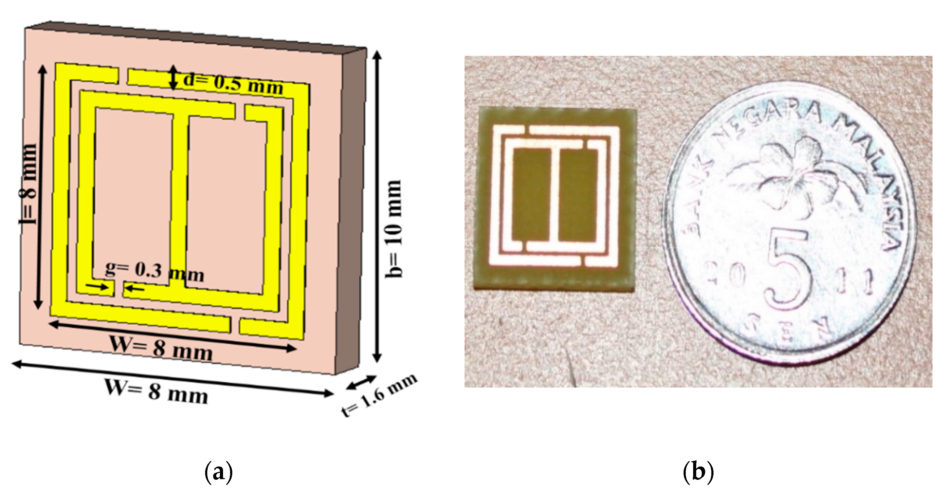
In the proposed design, an orthogonal metal strip of copper (thickness, h = 0.035 mm and conductivity, σ = 5.8 × 10⁷ S/m) is placed in such a way in the inner split square-shaped ring resonator to form an I-shaped structure. A diagram of the proposed unit cell is shown in Figure 2 and the array structure is shown in Figure 3. Two equal gaps in every ring produce the capacitive effect, symbolized by “g,” and each metal strip is responsible for generating inductance. Epoxy resin fiber is used as substrate material and has a dielectric constant of 4.5 and a loss tangent of 0.02. Table 1 reveals the dimensions of the recommended meta-atom unit cell.
3. Methodology
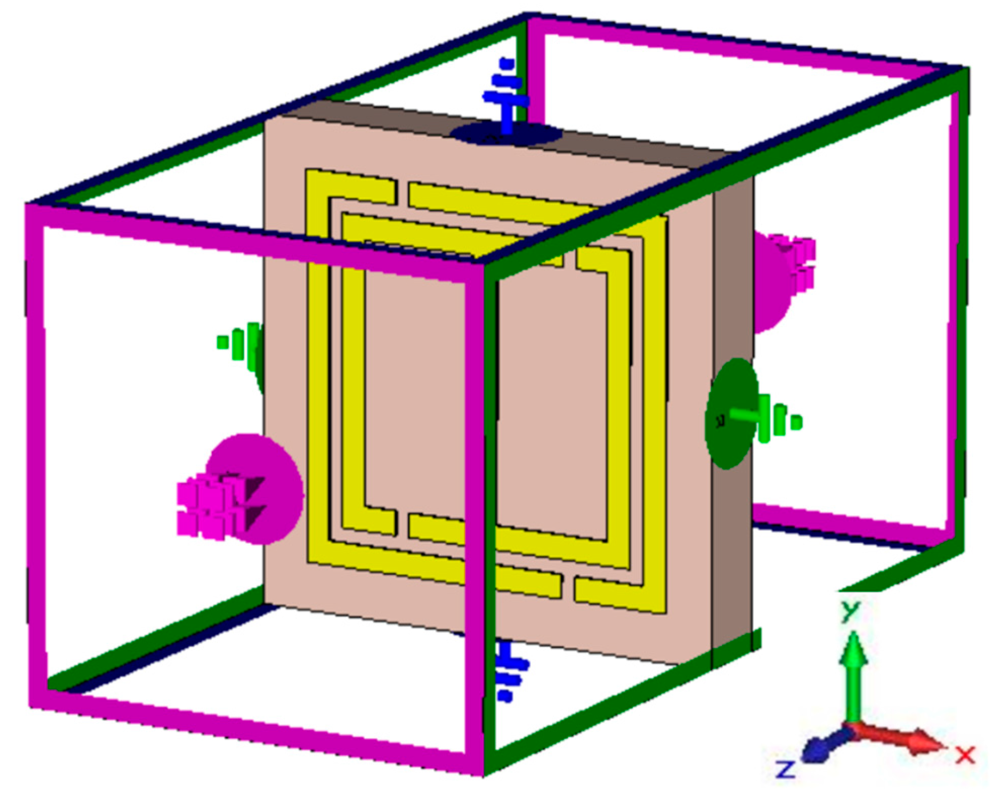
For numerical analysis of the proposed unit cell, the finite integration technique-based CST Microwave Studio has been used. In the simulation technique, the unit-cell structure is placed between two waveguide ports, and the electromagnetic waves are set to propagate in the z-directions. Perfect electric and magnetic boundaries are considered in the x- and y-directions shown in Figure 4. A frequency-domain solver with a tetrahedral mesh is utilized for simulation from 2–14 GHz.
The reflection (S11) and transmission (S21) coefficients are analyzed to realize the electromagnetic properties of the anticipated structure [24,25]. However, S11 and S21 can be written as,
The effective permittivity (ε) can be calculated by,
The effective permeability (μ) can be obtained from,
Therefore, the refractive index (n) can be expressed as follows,
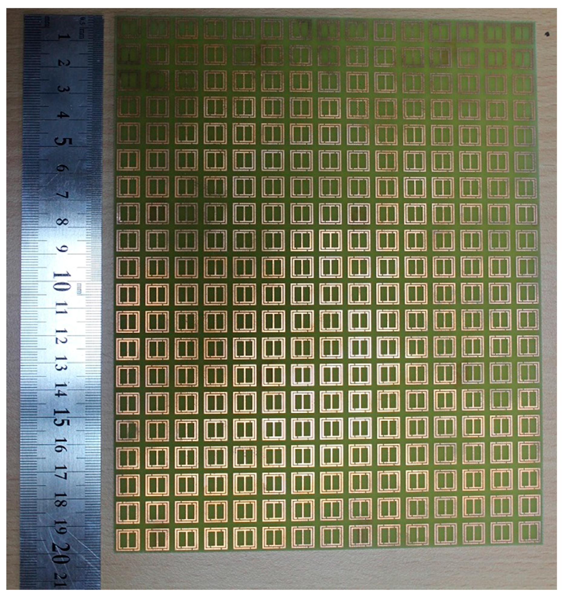
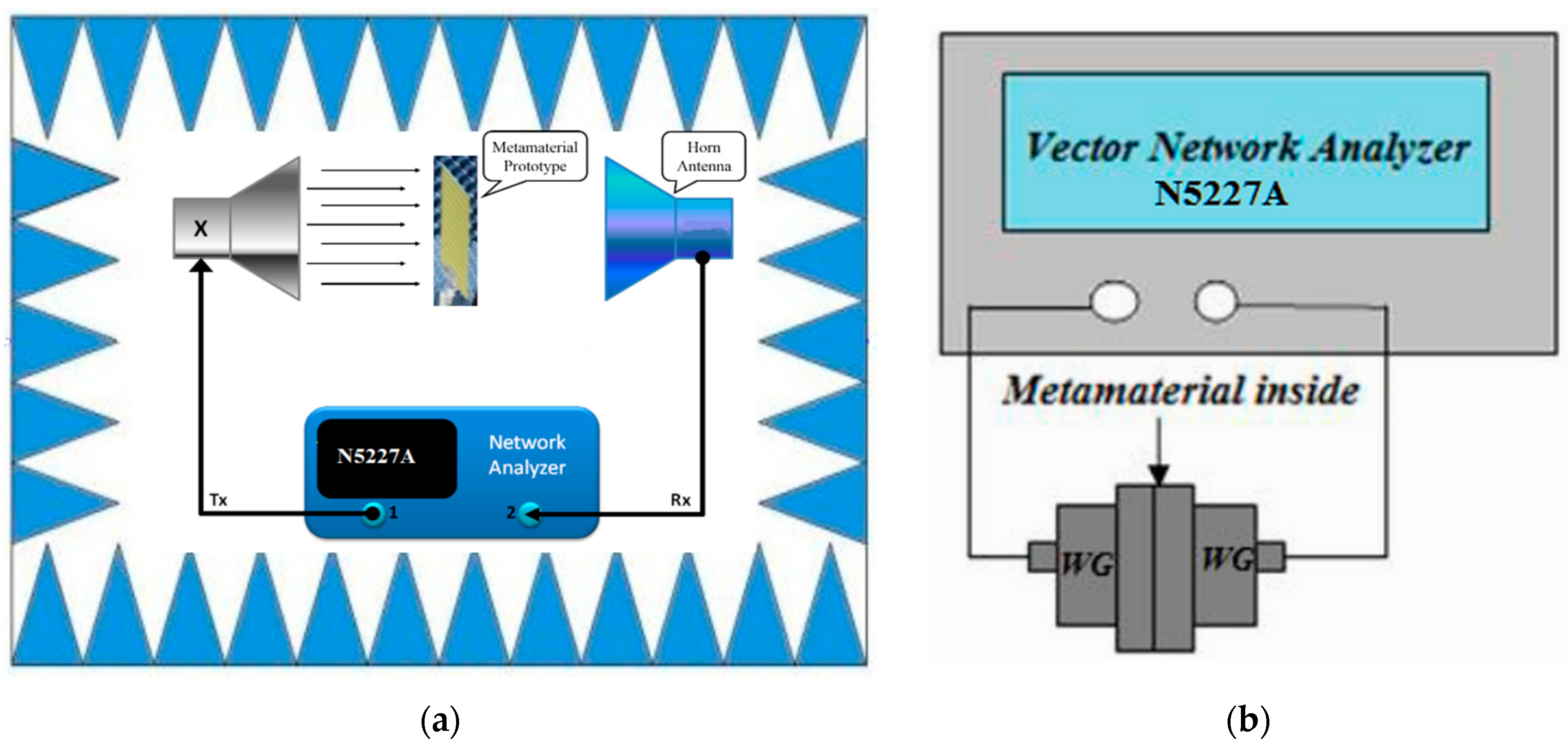
where k = ω/C and the angular frequency ω = 2πf. Measurement of the meta-atom is performed by the two horn antenna (frequency range from 700 MHz–18 GHz) in a semi-anechoic chamber, placed 1 m apart to satisfy the far-field condition. For measurement purposes, the fabricated prototypes utilize a horn antenna. A fabricated 150 × 200-mm2 (15 × 20 unit cells) array prototype, displayed in Figure 3, is placed within two horn antennas (from 700 MHz–18 GHz) in a semi-anechoic chamber. The chamber is surrounded by a wedge tapered absorber. The incident electromagnetic waves travel over the prototype similar to the simulated geometry. The horn antennas are connected to the Agilent N5227A vector network analyzer to obtain the reflection and transmission coefficient of the I-shaped meta-atom unit cell. Moreover, for additional experimental accuracy, the designed structure is also measured by the waveguides method [26]. The measured results of the both methods are almost similar to the proposed meta-atom structure. In addition, in the waveguide method, the fabricated 10 × 10-mm2 unit cell is placed between the waveguide ports, which work as transmission and receiving terminals. A set of (WR284 (frequency range from 2–3.95 GHz), WR187 (frequency range from 3.95–5.85 GHz), WR137 (frequency range from 5.85–8.20 GHz), WR90 (frequency range from 8.20–12.40 GHz), WR62 (frequency range from 12.40–18 GHz)) waveguides to coaxial adapters is connected to the Agilent N5227A vector network analyzer via a semi-rigid cable for measuring the S-parameters of the operating frequency from 2–18 GHz. The waveguide experiment is performed in an open-space environment, and the measurement is performed accurately with an Agilent N4694-60001 for calibration and an Agilent N5227A as a vector network analyzer. The experimental setup for measurement purposes is shown in Figure 5.
4. Circuit Model of the Proposed Meta-Atom
The proposed meta-atom structure contains the inductive-capacitive circuit, so the resonance frequency (f),
The total inductance (LT) and capacitance (CT) for the proposed structure can be obtained from [27]. Therefore, the total inductance (LT) can be obtained from,
However, the total capacitance (CT) can be calculated by:
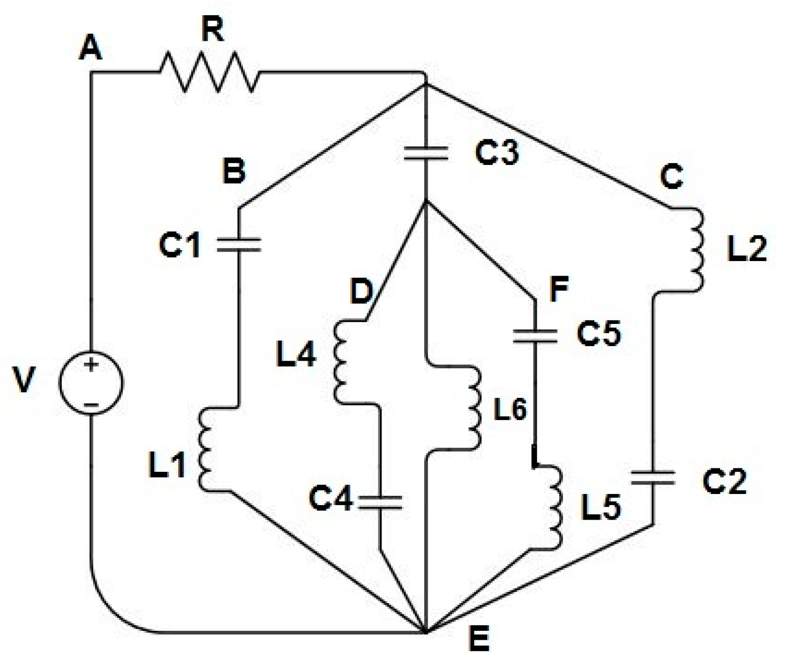
where the free-space permeability is µ0 = 4π × 10−7 H/m, the permittivity is ε0 = 8.854 × 10⁻¹² F/m and the parametric constant is τ = 0.0001. For left-handed characteristics, the series and shunt branch are formed by the inductive and capacitive effect. The capacitive effect is maintained by gaps or splits, which are symbolized by C1, C2, C3, C4 and C5 in the circuit shown in Figure 6. Conversely, the metal strips are accountable for the inductive effect and denoted by L1, L2, L3, L4, L5 and L6. When the width of the metal strip is increased, the inductive effect is also increased. As a result, owing to the inductive effect, the resonance frequency is decreased. Similarly, by decreasing the width and increasing the number of splits, the capacitive effect can be raised for the proposed unit cell, which swings the resonance frequency downwards [28]. However, the addition of further splits and metal arms in the meta-atom structure produces a small phase delay and increases the total inductive and capacitive effect.
In the above equivalent circuit, the current I (from the source) is divided into I1, I2, I3, I4, I5 and I6, where I = I1 + I2 + I3 + I4 + I5 + I6 (Kirchhoff’s first law). If the applied voltage is V and the charge in the capacitor is Q, then according to Kirchhoff’s second law, the differential equations for the loops are [29],
From the loop ABEA in the circuit model,
After the Laplace transformation,
From the loop BEDB in the circuit model,
After the Laplace transformation,
From the loop CEFC in the circuit model,
After the Laplace transformation,
From the loop DED in the circuit model,
After the Laplace transformation,
From the loop FEF in the circuit model,
After the Laplace transformation,
Similarly, the current passes through L6,
After Laplace transformation,
Therefore, from Equations (9)–(14), the corresponding current and field calculation can be obtained for the proposed unit cell.
5. Results Analysis
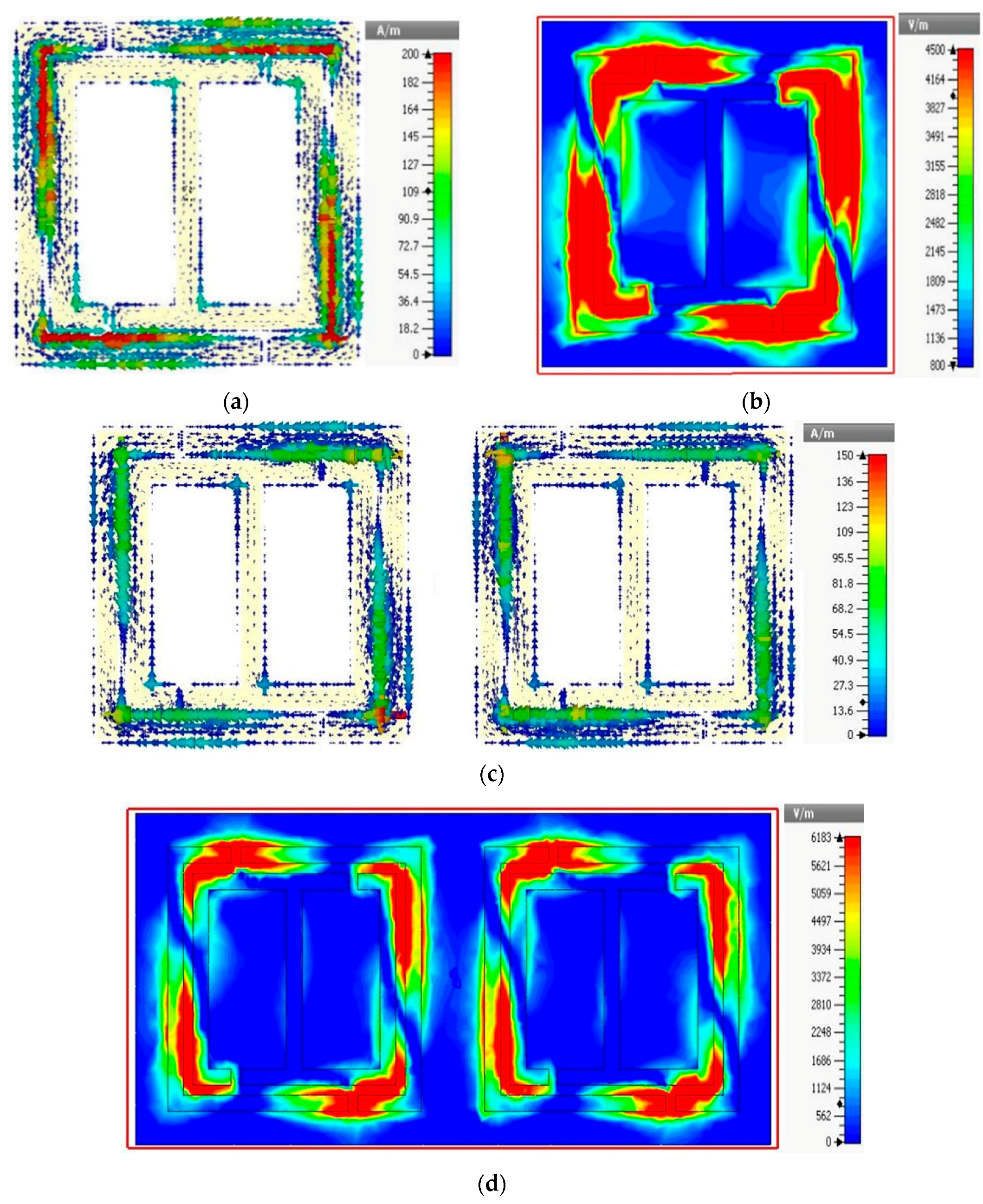
The current densities of the unit cell and 1 × 2 array at 12.94 GHz are shown in Figure 7a,c. Due to the dissimilar geometry of the meta-atom structure, the currents flow in opposite directions. In the resonator, opposite currents are flowing in the inner and outer surfaces, which causes the stop band at this frequency by cancelling the field. However, at 12.80 GHz, a strong electric field is also observed for the unit cell and 1 × 2 array structure in Figure 7b,d.
5.1. Unit Cell Analysis
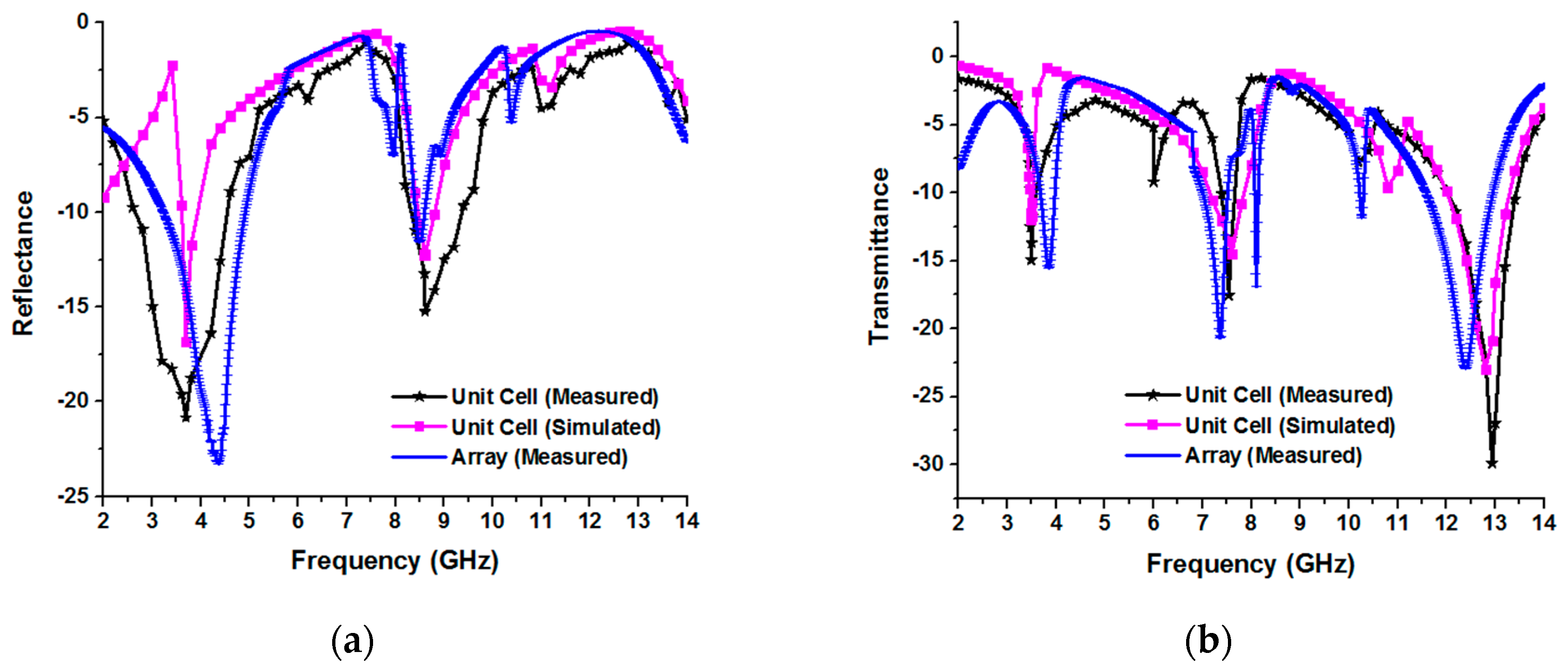
In Figure 8a,b, both the numerical and experimental reflection (S11) and transmission (S21) coefficients are shown. In Figure 8a, the simulation and experimental resonance frequencies of the reflection coefficient are almost the same at 3.7 GHz and 8.6 GHz of the unit cell. In addition, the measured resonance of the reflectance of the array structure at 4.21 GHz (magnitude of 23 dB) and 8.60 GHz (magnitude of 12 dB) is shown in the same Figure 8a. Figure 8b shows the triple-band resonance of the simulation at 3.48 GHz, 7.60 GHz and 12.84 GHz in the transmittance curve. The measured results exhibit resonance at 3.53 GHz (S-band), 7.54 GHz (C-band) and 12.94 GHz (Ku-band) in Figure 8b for the unit cell. The values of the resonances at 3.53 GHz, 7.54 GHz and 12.94 GHz are −14.95 dB, −17.56 dB and −29.91 dB, respectively. Moreover, the measured transmittance of the array structure exhibits the resonance frequency peaks at 4.0 GHz (magnitude of 16 dB), 7.41 GHz (magnitude of 21 dB), 8.10 GHz (magnitude of 17.50 dB), 10.30 GHz (magnitude of 12 dB) and 12.41 GHz (magnitude of 23 dB) in Figure 8b. However, owing to the measurement or fabrication errors, the measured result frequencies are slightly shifted and the magnitude extended compared with the simulated results.
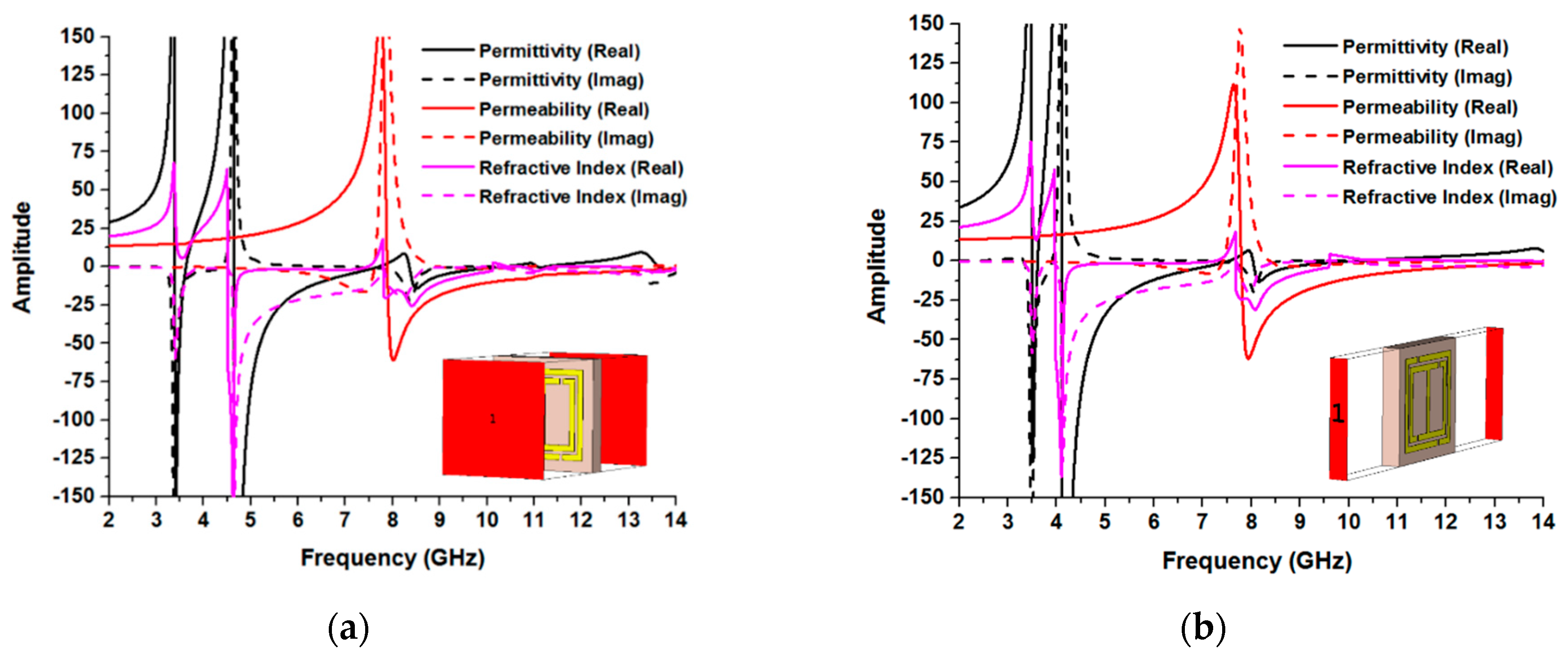
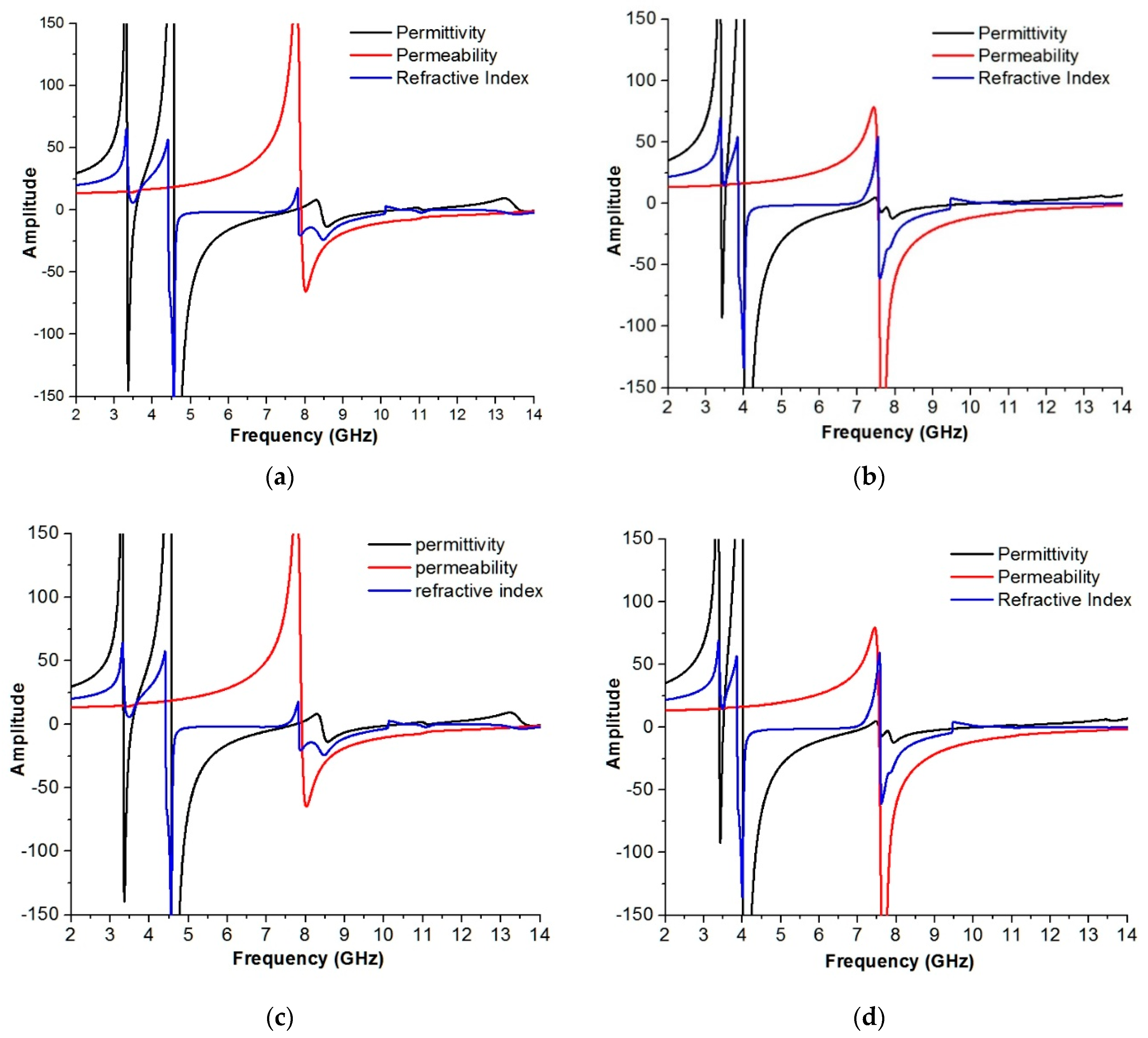
Figure 9 shows the unit cell amplitudes of the permittivity, permeability and refractive index at 0-degree, 90-degree, 180-degree and 270-degree rotations. Figure 9a demonstrations the negative permeability from 7.85–14 GHz (bandwidth of 6.15 GHz), negative permittivity from 4.60–7.70 GHz (bandwidth of 3.10 GHz) and 8.30 to 10.36 GHz (bandwidth of 2.06 GHz) and negative refractive index from 4.50 to 7.50 GHz (bandwidth of 3.0 GHz), 7.80 to 10.10 GHz (bandwidth of 2.30 GHz) and 12.60–14 GHz (bandwidth of 1.40 GHz) at zero-degree rotation. In addition, Figure 9b displays the permeability from 7.79–14 GHz (bandwidth of 6.21 GHz), permittivity from 4.11–7.53 GHz and 8–10.20 GHz. However, the refractive index is from 3.96–7.25 GHz and 7.68–9.60 GHz at 90-degree rotation. Furthermore, in Figure 9c, the unit cell at 180-degree rotation exhibits permeability from 7.90–14 GHz, permittivity from 4.66–7.12 GHz and 8.38–10.39 GHz and a refractive index from 4.53–7.47 GHz and 7.80–10.13 GHz. Additionally, permeability from 7.80–14 GHz, permittivity from 4.11–7.53 GHz and 8.03–10.17 GHz and a refractive index from 3.59–7.25 GHz and 7.68–9.59 GHz are shown in Figure 9d for 270-degree rotation of the proposed meta-atom unit cell. Here, it is revealed that there is a variation between the effective medium parameters because the properties of the effective medium parameters are mostly affected by the polarization owing to the internal architecture of the mate atom.
According to the left-handed or double-negative characteristics, the refractive index will be negative, if the unit cell permittivity and permeability appear negative simultaneously. From Figure 9, the unit cell structure exhibits left-handed characteristics at every rotation angle at 9.20 GHz, which are shown in Table 2. There is a variation of the effective medium ratio between zero-degrees and 90-degrees. Actually, the electric and magnetic fields are closely related and propagate as an electromagnetic wave. The electromagnetic wave is applied to the proposed meta-atom in the Z-direction. After application of the electromagnetic wave, the inner particles of the meta-atom structure start oscillating up and down, as well as toward the vibration. However, at time t = 0, T/2, there is a maximum separation of charge, where the negative charges are at the top and the positive charges are at the bottom, and a maximum amplitude is produced at lower frequencies. At t = T/4, 3T/4, there is a maximum charge separation, either positive or negative, and the amplitude at higher frequencies.
5.2. Meta-Atom Array Configurations
The performances of the 1 × 2, 2 × 2, 3 × 3 and 4 × 4 open array configurations are analyzed in this section under 0°, 90°, 180° and 270° rotation structures.
5.2.1. 1 × 2 Array Analysis
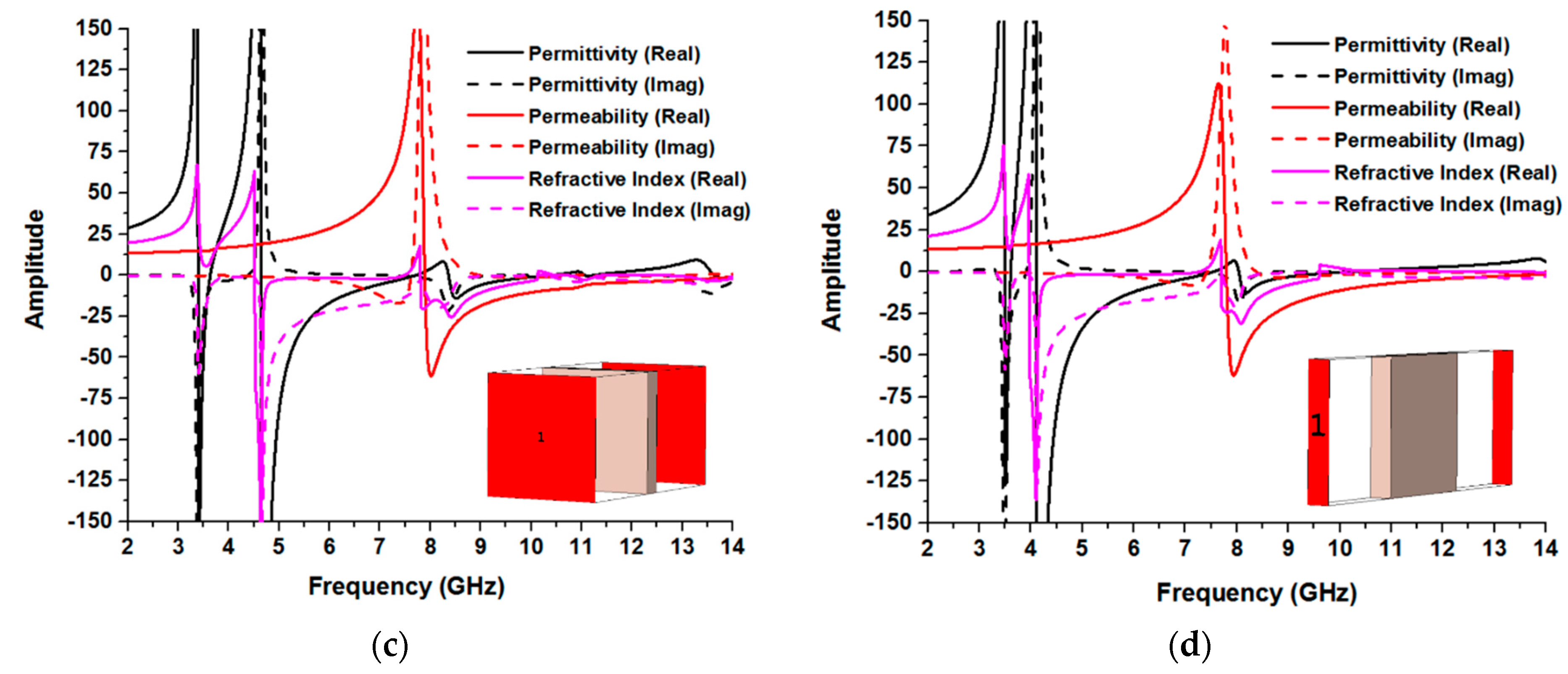
Figure 10 shows the effective medium parameter amplitudes at the different rotations of the 1 × 2 array geometry. The amplitudes of the permittivity, permeability and refractive index are plotted in the same Figure for every rotation. Figure 10a shows permittivity from 4.64–7.70 GHz (bandwidth of 3.06 GHz) and 8.36–10.36 GHz (bandwidth of 2 GHz), permeability from 7.89–14 GHz (bandwidth of 6.11 GHz) and a refractive index from 4.50–7.47 GHz, 7.80–10.11 GHz and 12.62–14 GHz at zero-degree rotation. Figure 10b exhibits permittivity from 4–7.19 GHz (bandwidth of 3.19 GHz) and 7.55–10.02 GHz (bandwidth of 2.47 GHz), permeability from 7.60–14 GHz (bandwidth of 6.40 GHz) and a refractive index from 3.86–6.86 GHz (bandwidth of 3 GHz) and 7.56–9.45 GHz (bandwidth of 1.89 GHz) at 90-degree rotation. Furthermore, in Figure 10c at 180-degree rotation, the unit cell displays permittivity from 3.34–3.54 GHz (bandwidth of 0.20 GHz), 4.58–7.72 GHz (bandwidth of 3.14 GHz) and 8.42–10.41 GHz (bandwidth of 1.99 GHz); permeability from 7.90–14 GHz (bandwidth of 6.10 GHz); and a refractive index from 4.42–7.48 GHz, 7.83–10.11 GHz and 12.54–14 GHz. Additionally, permittivity of 4.01–7.19 GHz (bandwidth of 3.18 GHz) and 7.55–10.02 GHz (bandwidth of 2.47 GHz); permeability from 7.55–14 GHz (bandwidth of 6.45 GHz); and a refractive index from 3.87–6.84 GHz, 7.59–9.45 GHz and 11–11.25 GHz are shown in Figure 10d for 270-degree rotation of the proposed meta-atom unit cell. At 9.20 GHz, the permittivity, permeability and refractive index curves display negative peaks. As a result, the array structure appearances as double-negative meta-atoms are shown in Table 3.
5.2.2. 2 × 2 Array Analysis
The same methodology is applied to investigate the 2 × 2 array configuration at 0-degree, 90-degree, 180-degree and 270-degree rotations. It is visible from Figure 11a that there is a negative value from 7.84–14 GHz for permeability; a negative value from 4.56–7.79 GHz, 8.13–8.69 GHz and 8.92–10.36 GHz for permittivity; and a negative value from 4.48–6.68 GHz, 7.80–10.22 GHz and 12.22–14 GHz for the refractive index at zero-degree rotation. In addition, Figure 11b exhibits negative values from 7.74–14 GHz for permeability; negative values from 3.96–8.63 GHz and 8.74–10.13 GHz for permittivity; and negative values from 4.31–6.48 GHz, 6.98–7.52 GHz and 7.76–9.64 GHz for the refractive index at 90-degree rotation. Furthermore, in Figure 11c at 180-degree rotation, the unit cell displays negative permeability from 7.85–14 GHz; negative permittivity from 4.59–7.74 GHz and 8.94–10.60 GHz; and a negative refractive index from 4.48–6.70 GHz, 7.82–10.28 GHz and 12.27–14 GHz. Additionally, negative permeability from 7.77–14 GHz, negative permittivity from 4–10.16 GHz and a negative refractive index from 4.40–6.52 GHz and 7.77–9.69 GHz are shown in Figure 11d for 270-degree rotation of the proposed meta-atom unit cell. As the size of the structure increases, the resonance frequencies decrease, and the number of resonances also increases. The overall size of the structure is responsible for creating a larger inductive effect. With increasing inductance, the resonance frequency shifts to lower frequencies. In addition, splits and gaps are formed by the capacitive effect. As the number of unit cells varies, the number of splits and gaps between the resonators increases with the overall size of the unit cell. With the increasing number of splits and gaps, more capacitance and resonance points are formed. In addition, if the inductive and capacitive effects increase, the inductance and capacitance minimize each other and create more stop bands and resonance points. Moreover, the resonances also depend on the material’s internal structure. When EM-waves propagate through a material, its electric and magnetic fields oscillate in a sinusoidal pattern, and their velocity depends on the material’s electrical conductivity, which in turn depends on the material’s internal structure. The relative speed of electrical signals traveling through a material varies according to how they interact with its internal structure. Moreover, from Table 4, the effective medium ratio at zero-degree and 180-degree rotation is 8.6 and 4.5 for 90-degree and 270-degree rotation.
5.2.3. 3 × 3 Array Analysis
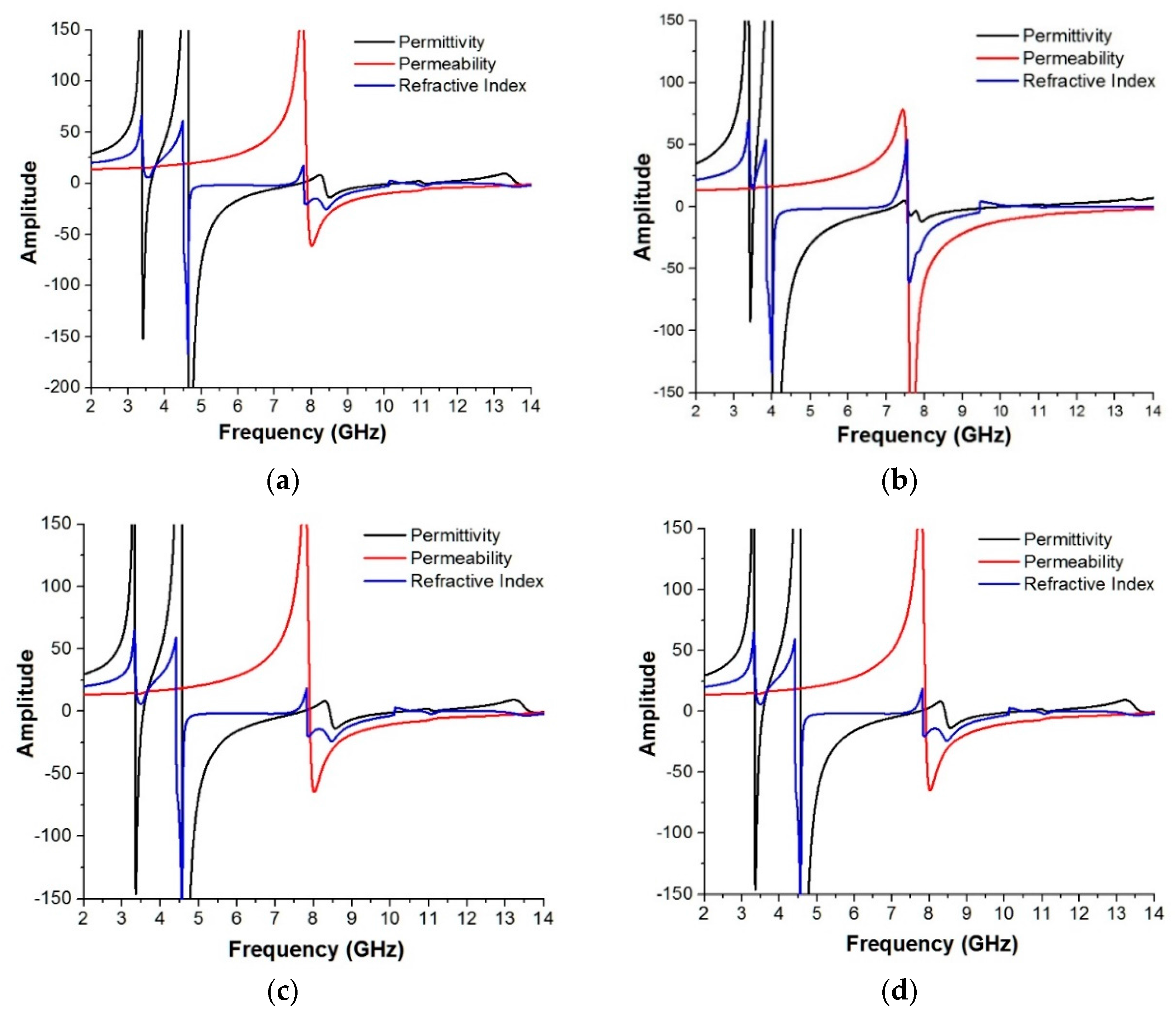
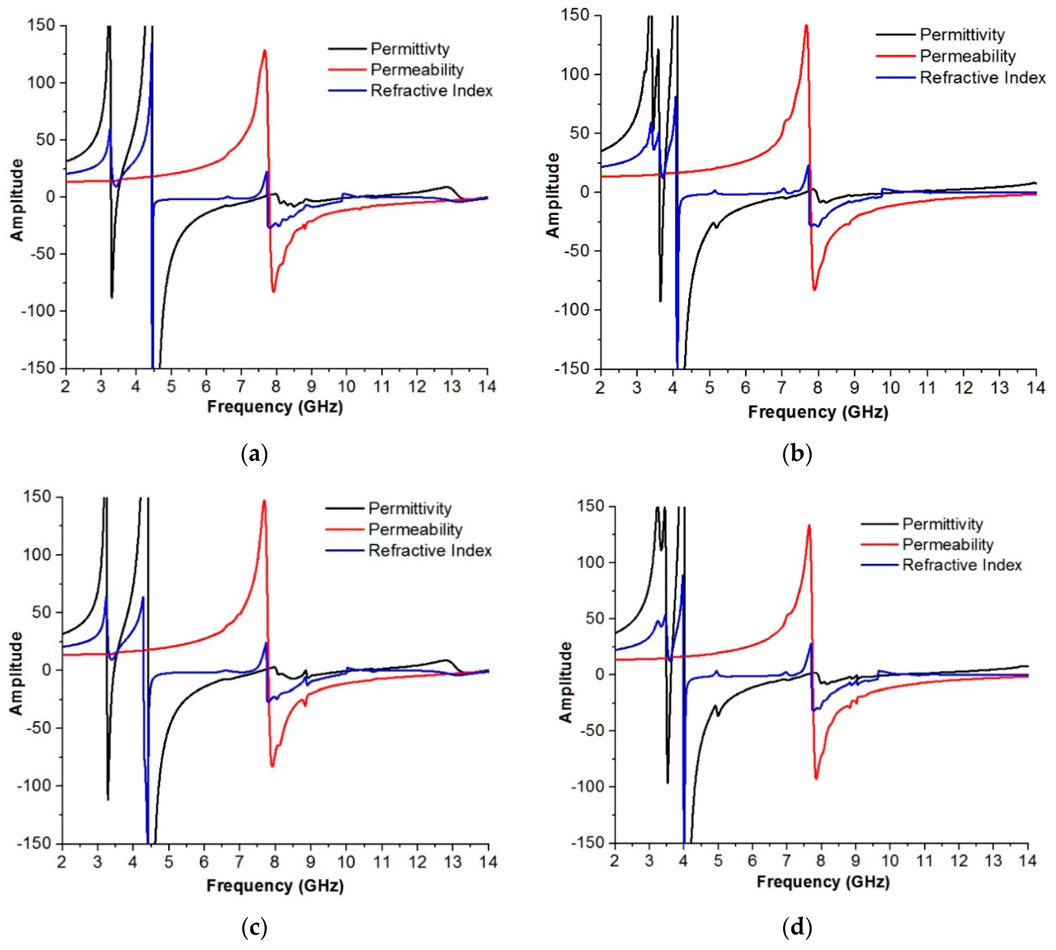
From Figure 12a, the frequency spans of the negative effective permittivity, permeability and refractive index of the array structure are from 4.58–7.72 GHz and 8.42–10.40 GHz; 7.90–14 GHz; and 4.42–7.48 GHz, 7.83–10.10 GHz and 12.54–14 GHz, respectively. Moreover, in Figure 12b at 90-degree rotation, the frequency spans of the permittivity, permeability and refractive index are from 4–7.19 GHz and 7.55–10.02 GHz; 7.55–14 GHz; and 3.86–6.86 GHz and 7.56–9.45 GHz, respectively. At 180-degree rotation, the frequency spans are from 4.58–7.72 GHz and 8.42–10.41 GHz (permittivity); 7.90–14 GHz (permeability); and 4.42–7.48 GHz, 7.83–10.11 GHz and 10.80–11.32 GHz (refractive index), as explained in Figure 12c. However, Figure 12d shows that the negative permittivity, permeability and refractive index are sequentially from 4–7.19 GHz and 7.55–10 GHz; 7.55–14 GHz; 3.87–6.84 GHz and 7.59–9.45 GHz and left handed properties in Table 5.
5.2.4. 4 × 4 Array Analysis
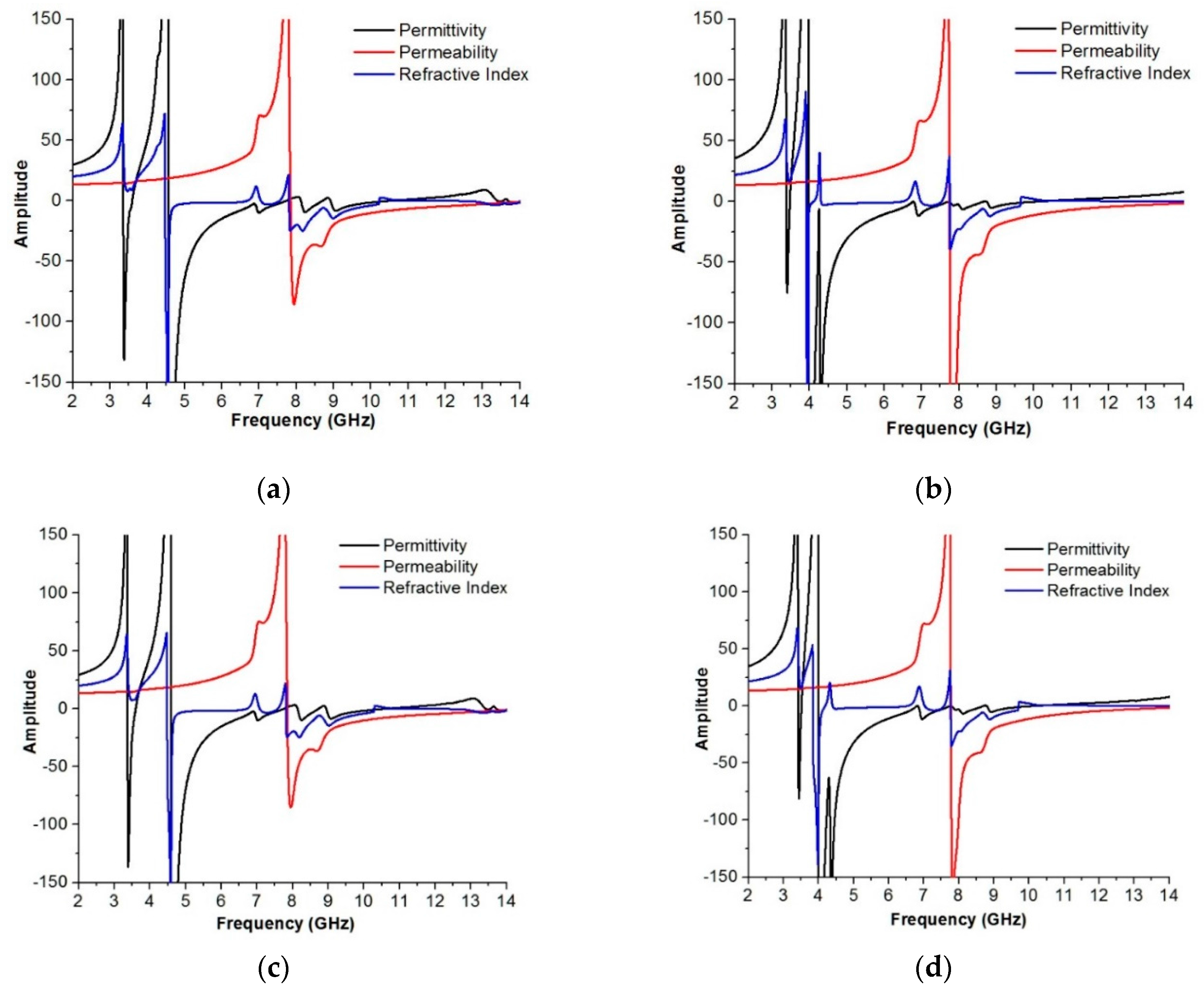
In Figure 13, the effective medium parameters are depicted at 0°, 90°, 180° and 270° rotations. From Figure 14a, the permeability is from 7.79–14 GHz, covering almost 6.21 GHz in bandwidth; the permittivity is from 4.46–7.58 GHz, covering approximately 3.12 GHz in bandwidth; and the refractive index is from 4.44–6.54 GHz and 7.73–9.86 GHz, covering almost 2.10 GHz and 2.13 GHz for zero-degree rotation. In Figure 14d, the permeability ranges from 7.74–14 GHz, covering almost 6.26 GHz in bandwidth; the permittivity ranges from 4–7.53 GHz and 7.90–10 GHz, covering bandwidths of approximately 3.53 GHz and 2.10 GHz; and the refractive index ranges from 5–7.20 GHz (2.20 GHz in bandwidth) and 7.71–9.63 GHz (1.92 GHz in bandwidth) for 270-degree rotation. Therefore, it is notable that the bandwidth of the permeability is always more than 6 GHz for all of the rotation angles. The array structure also shows left-handed characteristics at 9.20 GHz, with an effective medium ratio of more than 8 for 0-degree and 180-degree and 4 for 90-degree and 270-degree rotation, as shown in Table 6.
The sensitivity of the proposed meta-atom has been explained in terms of the Q-factor. The bandwidth of the meta-atom is inversely related to the quality factor (Q-factor). The calculation of the Q factor has been performed using the 3-dB bandwidth of resonant frequency (Δf) and the resonant frequency (f0) that has a resonance peak under −10 dB.
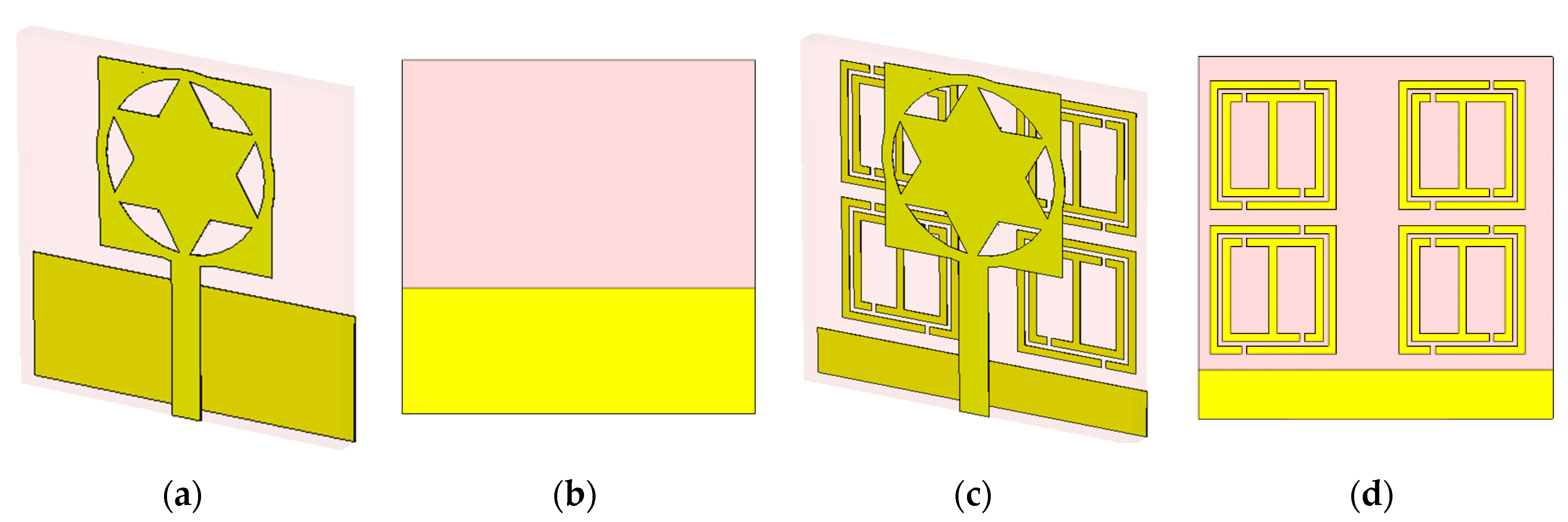
It can be observed that the Q-factor is high, and this means that the reported meta-atom has high sensibility. The value of the Q-factor depends on the sharpness of the transmission and the location of resonant frequency. The reported antenna has been designed to use for long distance telecommunication (C-band). This antenna is made of three layers; they are radiating patch, antenna substrate and ground plane. The ground plane is printed on the lower part of the substrate, where on the upper portion of the substrate, the radiating patch is printed using a microstrip line feeding in Figure 14a,b. The width and length of the microstrip line are stable with a view to attaining the 50 Ω input impedance. The port of the microstrip feed line is attached to a Sub-Miniature Version A (SMA) connector. To attain the adequate wide bandwidth, multi frequency bands and high performances, the ground plane of the proposed antenna has been replaced by the meta-atoms. Moreover, after replacing the antenna ground plane by the meta-atoms, then the SMA connector is connected with the partial ground integrated with the meta-atoms shown in Figure 14c,d.
From Figure 15a, the resonance of the return loss of the meta-atom antenna are respectively at 4.22, 6.30, 7.22, 11.34 and 13.68 GHz, whereas the bandwidth are sequentially 130 MHz (from 4.20 to 4.33 GHz), 120 MHz (from 6.26 to 6.38 GHz), 200 MHz (from 7.10 to 7.30 GHz), 2.17 GHz (from 9.93 to 12.10 GHz) and 0.9 GHz (from 13.10 to 14 GHz). On the contrary, the designed antenna without integrating the meta-atom of the ground plane has the resonance at 5.67 and 7.79 GHz. Therefore, after integrating the proposed meta-atom by replacing the ground plane, the antenna resonance peaks and frequency bands have been improved. In addition, in Figure 15b, from the gain curve, it can also be commented that the antenna with the meta-atom has achieved an average gain of almost 2.85 dB at the resonance bandwidth regions. The maximum peak gain is around 5 dB.
Table 7 depicts the quality factors of the proposed meta-atom and that reported in [17,23]. In [17], the sensitivity was 14, and in [23], it was 31; but for the proposed structure, the sensitivity is 82, which is more than the previous one. Besides, for the high quality factor, making of the designed meta-atom is flexible for high-performance filters and sensor applications. Table 8, represents a comparison between the frequency bands and effective medium ratios of the proposed design with the previous design. For the compactness of the meta-atom, an effective medium ratio is an important factor. The proposed meta-atom unit cell exhibits an effective medium ratio (EMR) of 8.50, which is greater than that of the other unit cells. As a result, the designed structure is more suitable and compact in size. Moreover, the proposed meta-atom structure is applicable for S-, C- and Ku-band applications.
From Table 9, Mallik et al. discussed 1 × 2 and 2 × 2 arrays at an orthogonal position [16]. Islam et al. presented 2 × 2 array structures for double-negative characteristics and multi-band applications [17]. Hossain et al. showed a 2 × 2 array configuration under open and interconnect conditions. In their framework, they analyzed the effect on resonances by changing the dimensions of the arrays [18]. In this study, the left-handed characteristics, compactness, frequency band and bandwidth of 1 × 2, 2 × 2, 3 × 3 and 4 × 4 arrays are analyzed by 0°, 90°, 180° and 270° rotations.
6. Conclusions
A new compact left-handed meta-atom for S-, C- and Ku-band applications has been designed, investigated, fabricated and measured in this paper. The unit cell and array structure exhibited left-handed characteristics with wide bandwidths in the major portions of S-, C- and Ku-bands at 0°, 90°, 180° and 270° rotations. For the design, simulation and calculation of the S-parameters of the proposed meta-atom prototype, CST Microwave Studio has been used. Both the horn antenna and waveguide methods have been used for measurement purposes to obtain greater accuracy in the measured results. In addition, S-band is applicable for weather radar monitoring and microwave devices. C-band is relevant in radio telecommunication and electromagnetic cloaking, and the Ku-band is significant for satellite applications.
Acknowledgments
This work was supported by the Research Universiti Grant, Arus Perdana Code: AP-2015-007.
Author Contributions
Md. Mehedi Hasan made substantial contributions to the conception, design and analysis. Mohammad Rashed Iqbal Faruque participated in revising the article critically for important intellectual contents. Mohammad Tariqul Islam provided necessary instructions for experimental purposes.
Conflicts of Interest
The authors declare no conflict of interest.
References
- Hasan, M.M.; Faruque, M.R.I.; Islam, M.T. A tri-band microwave perfect metamaterial absorber. Microw. Opt. Technol. Lett. 2017, 59, 2302–2307. [Google Scholar] [CrossRef]
- Armghan, A.; Hu, X.; Yuan, S.; Xia, J. Negative refractive index metamaterial structure using SRR by incidenting the light horizontally. J. Electromagn. Anal. Appl. 2015, 7, 276–282. [Google Scholar] [CrossRef]
- Purushothaman, N.; Jain, A.; Taube, W.R.; Gopal, R.; Ghosh, S.K. Modelling and fabrication studies of negative permeability metamaterial for use in waveguide applications. Microsyst. Technol. 2015, 21, 2415–2424. [Google Scholar] [CrossRef]
- Alam, T.; Faruque, M.R.I.; Islam, M.T. A double-negative metamaterial-inspired mobile wireless antenna for electromagnetic absorption reduction. Materials 2015, 8, 4817–4828. [Google Scholar] [CrossRef] [PubMed]
- Yang, S.; Liu, P.; Yang, M.; Wang, Q.; Song, J.; Dong, L. From flexible and stretchable meta-atom to metamaterial: A wearable microwave meta-skin with tunable frequency selective and cloaking effects. Sci. Rep. 2016, 6, 21921. [Google Scholar] [CrossRef] [PubMed]
- Xiao, S.; Chettiar, U.K.; Kildishev, A.V.; Drachev, V.P.; Shalaev, V.M. Yellow-light negative-index metamaterials. Opt. Lett. 2009, 34, 3478–3480. [Google Scholar]
- Soukoulis, C.M.; Wegener, M. Optical Metamaterials—More Bulky and Less Lossy. Science 2010, 330, 1633–1634. [Google Scholar]
- Ganse, J.K.; Thiel, M.; Rill, M.S; Decker, M.; Bade, K.; Saile, V.; Freymann, G.V.; Linden, S.; Wegener, M. Gold Helix Photonic Metamaterial as Broadband Circular Polarizer. Science 2009, 325, 1513–1515. [Google Scholar]
- Gao, J.; Sun, L.; Deng, H.; Mathai, C.J.; Gangopadhyay, S. Experimental realization of epsilon-near-zero metamaterial slabs with metal-dielectric multilayers . Appl. Phys. Lett. 2013, 103, 051111. [Google Scholar]
- Chen, Y.; Yao, H.; Wang, L. Acoustic band gaps of three-dimensional periodic polymer cellular solids with cubic symmetry. Appl. Phys. Lett. 2013, 114, 043521. [Google Scholar]
- Ji, R.; Wang, S.W.; Liu, E.L.; Chen, M.C.; Lu, W. Broadband circular polarizers constructed using helix-like chiral metamaterials. Nanoscale 2016, 8, 14725–14729. Available online: http://0-pubs-rsc-org.brum.beds.ac.uk/en/content/articlelanding/2016/nr/c6nr01738j#!divAbstract (accessed on 4 January 2018).
- Wang, L.; Lau, J.; Thomas, E.L.; Boyce, M.C. Acoustic band gaps of three-dimensional periodic polymer cellular solids with cubic symmetry. Adv. Mater. 2011, 23, 1524–1529, Copyright Wiley-VCH Verlag GmbH & Co. KGaA. Reproduced with permission. [Google Scholar]
- Veselago, V.G. The electrodynamics of substances with simultaneously negative values of ε and μ. Sov. Phys. 1968, 10, 509–514. [Google Scholar] [CrossRef]
- Pendry, J.B.; Holden, A.J.; Robbins, D.J.; Stewart, W.J. Magnetism from conductors and enhanced nonlinear phenomena. IEEE Trans. Microw. Theory Tech. 1999, 47, 2075–2084. [Google Scholar] [CrossRef]
- Smith, D.R.; Padilla, W.J.; Vier, D.C.; Nasser, S.C.N.; Schultz, S. Composite medium with simultaneously negative permeability and permittivity. Phys. Rev. Lett. 2000, 84, 4184–4187. [Google Scholar] [CrossRef] [PubMed]
- Mallik, A.; Kundu, S.; Goni, M.O. Design of a novel two-rectangular U-shaped double negative metamaterial. In Proceedings of the International Conference on Informatics, Electronics and Vision, Dhaka, Bangladesh, 17–18 May 2013; pp. 1–4. [Google Scholar]
- Islam, S.S.; Faruque, M.R.I.; Islam, M.T. The design and analysis of a novel split-H-shaped metamaterial for multi-band microwave applications. Materials 2014, 7, 4994–5011. [Google Scholar] [CrossRef] [PubMed]
- Hossain, M.I.; Faruque, M.R.I.; Islam, M.T.; Ullah, M.H. A new wide-band double-negative metamaterial for C- and S-B and applications. Materials 2015, 8, 57–71. [Google Scholar] [CrossRef] [PubMed]
- Zhou, H.; Wang, C.; Peng, H. A novel double-incidence and multi-band left-handed metamaterials composed of double Z-shaped structure. J. Mater. Sci. Mater. Electron. 2015, 27, 2534–2544. [Google Scholar] [CrossRef]
- Du, B.; Xu, Z.; Wang, J.; Xia, S. Magnetically tunable ferrite-dielectric left-handed metamaterial. Electromagn. Res. C 2016, 66, 21–28. [Google Scholar] [CrossRef]
- Hasan, M.M.; Faruque, M.R.I.; Islam, S.S.; Islam, M.T. A new compact double-negative miniaturized metamaterial for wideband operation. Materials 2016, 9, 830. [Google Scholar] [CrossRef] [PubMed]
- Liu, S.-H.; Guo, L.-X.; Li, J.-C. Left-handed metamaterials based on only modified circular electric resonators. J. Mod. Opt. 2016, 63, 2220–2225. [Google Scholar] [CrossRef]
- Hasan, M.M.; Faruque, M.R.I.; Islam, M.T. Parametric studies on split S-shaped composite Meta atom for X-band communication. Bull. Pol. Acad. Sci. Tech. Sci. 2017, 5, 533–539. [Google Scholar] [CrossRef]
- Islam, S.S.; Faruque, M.R.I.; Islam, M.T. A new direct retrieval method of refractive index for metamaterials. Curr. Sci. 2015, 109, 337–342. [Google Scholar]
- Hasan, M.M.; Faruque, M.R.I.; Islam, M.T. Composite left-handed meta-atom for tri-band operation. Mater. Res. Express 2017, 5, 1–9. [Google Scholar] [CrossRef]
- Turkmen, O.; Ekmekci, E.; Turhan-Sayan, G. Nested U-ring resonators: A novel multi-band metamaterial design in microwave region. IET Microw. Antennas Propag. 2012, 6, 1102–1108. [Google Scholar] [CrossRef]
- Clayton, R.P. Inductance: Loop and Partial; Wiley-IEEE Press: Hoboken, NJ, USA, 2009; pp. 56–63. [Google Scholar]
- Hasan, M.M.; Faruque, M.R.I.; Islam, M.T. A mirror shape chiral Meta atom for C-band communication. IEEE Access 2017. [Google Scholar] [CrossRef]
- Ziemer, R.E.; Tranter, W.H.; Fannin, D.R. Signals and Systems: Continues and Discrete; Macmillan Publishing Company: New York, NY, USA, 1997; pp. 255–263. [Google Scholar]
Figure 1.
Examples of several meta-atom based metamaterial (MTM) structures through periodic repetition of metallic and dielectric elements: (a) double-fishnet negative-index metamaterial with several layers. Reproduced with permission from [Xiao, S. et al.], [Opt. Lett.]; published by [The Optical Society], [2009] [6]; (b) chiral metamaterial fabricated through stacked electron-beam lithography. From [Soukoulis, C.M. et al. Optical Metamaterials—More Bulky and Less Lossy. Science 2010, 330, 1633–1634]. Reprinted with permission from Soukoulis, C.M. [7]; (c) chiral metamaterial made using direct-laser writing and electroplating. From [Ganse, J.K. et al. Gold Helix Photonic Metamaterial as Broadband Circular Polarizer. Science 2009, 325, 1513–1515]. Reprinted with permission from AAAS [8]; (d) hyperbolic metamaterial made by electroplating hexagonal-hole-array templates. From [Ganse, J.K. et al. Gold Helix Photonic Metamaterial as Broadband Circular Polarizer. Science 2009, 325, 1513–1515]. Reprinted with permission from AAAS [8]; (e) metal-dielectric layered metamaterial composed of coupled plasmonic waveguides Reproduced from [Gao, J. et al. Experimental realization of epsilon-near-zero metamaterial slabs with metal-dielectric multilayers. Appl. Phys. Lett. 2013, 103, 051111], with the permission of AIP Publishing [9]; (f) Split ring resonators (SRRs) oriented in all three dimensions. Reproduced from [Chen, Y. et al. Acoustic band gaps of three-dimensional periodic polymer cellular solids with cubic symmetry. Appl. Phys. Lett. 2013, 114, 043521], with the permission of AIP Publishing [10]; (g) wide-angle visible negative-index metamaterial based on a coaxial design. From [Soukoulis, C.M. et al. Optical Metamaterials—More Bulky and Less Lossy. Science 2010, 330, 1633–1634]. Reprinted with permission from Soukoulis, C.M. [7]; (h) connected cubic-symmetry negative-index metamaterial. Reproduced with permission from [Ji. R. et al.], [Nanoscale]; published by [Royal Society of Chemistry], [2016] [11]; (i) metal cluster-of-clusters visible-frequency magnetic metamaterial. Reproduced with permission from [Wang, L. et al.], [Adv. Mater.]; published by [Wiley], [2011] [12]; (j) negative-index metamaterial composed of two sets of high-refractive-index dielectric spheres arranged on a simple cubic lattice. NRI, negative refractive index. Reproduced with permission from [Wang, L. et al.], [Adv. Mater.]; published by [Wiley], [2011] [12].

Figure 2.
Meta-atom unit cell: (a) proposed structure, (b) fabricated structure.

Figure 3.
Fabricated 150 × 200-mm2 (15 × 20 unit cells) array prototype of the proposed meta-atom structure.
Figure 3.
Fabricated 150 × 200-mm2 (15 × 20 unit cells) array prototype of the proposed meta-atom structure.

Figure 4.
Simulation setup with boundary condition in CST-MWS.

Figure 5.
Experimental setup for measuring the S11 and S21 parameters: (a) horn antenna method; (b) waveguide (WG) method.
Figure 5.
Experimental setup for measuring the S11 and S21 parameters: (a) horn antenna method; (b) waveguide (WG) method.

Figure 6.
Equivalent circuit model of the proposed meta-atom structure.

Figure 7.
Surface current at 12.94 GHz of: (a) single unit cell and (c) 1 × 2 array structure. Numerical electric field distribution in the XY plane at 12.94 GHz for: (b) single unit cell and (d) 1 × 2 array structure.
Figure 7.
Surface current at 12.94 GHz of: (a) single unit cell and (c) 1 × 2 array structure. Numerical electric field distribution in the XY plane at 12.94 GHz for: (b) single unit cell and (d) 1 × 2 array structure.

Figure 8.
Magnitude (in dB) of: (a) the reflection coefficient (S11) and (b) the transmission coefficient (S21).
Figure 8.
Magnitude (in dB) of: (a) the reflection coefficient (S11) and (b) the transmission coefficient (S21).

Figure 9.
Amplitude of the permittivity, permeability and refractive index at: (a) 0°, (b) 90°, (c) 180°, (d) 270° rotations.
Figure 9.
Amplitude of the permittivity, permeability and refractive index at: (a) 0°, (b) 90°, (c) 180°, (d) 270° rotations.


Figure 10.
Amplitude of the permittivity, permeability and refractive index at: (a) 0°, (b) 90°, (c) 180°, (d) 270° rotation of the 1 × 2 array structure.
Figure 10.
Amplitude of the permittivity, permeability and refractive index at: (a) 0°, (b) 90°, (c) 180°, (d) 270° rotation of the 1 × 2 array structure.

Figure 11.
Amplitude of the permittivity, permeability and refractive index at: (a) 0°, (b) 90°, (c) 180°, (d) 270° rotations of the 2 × 2 array structure.
Figure 11.
Amplitude of the permittivity, permeability and refractive index at: (a) 0°, (b) 90°, (c) 180°, (d) 270° rotations of the 2 × 2 array structure.

Figure 12.
Amplitude of the permittivity, permeability and refractive index at: (a) 0°, (b) 90°, (c) 180°, (d) 270° rotations of the 3 × 3 array structure.
Figure 12.
Amplitude of the permittivity, permeability and refractive index at: (a) 0°, (b) 90°, (c) 180°, (d) 270° rotations of the 3 × 3 array structure.

Figure 13.
Amplitude of the permittivity, permeability and refractive index at: (a) 0°, (b) 90°, (c) 180°, (d) 270° rotations of the 4 × 4 array structure.
Figure 13.
Amplitude of the permittivity, permeability and refractive index at: (a) 0°, (b) 90°, (c) 180°, (d) 270° rotations of the 4 × 4 array structure.

Figure 14.
The geometry of the: (a) antenna transparent 3D view, (b) ground plane without integrated meta-atom back view, (c) antenna transparent 3D view of integrated meta-atom with ground plane, (d) ground plane replaced by integrated meta-atom, back view.
Figure 14.
The geometry of the: (a) antenna transparent 3D view, (b) ground plane without integrated meta-atom back view, (c) antenna transparent 3D view of integrated meta-atom with ground plane, (d) ground plane replaced by integrated meta-atom, back view.

Figure 15.
Antenna performances: (a) return loss (S11), (b) gain; without and with the meta-atom at the ground plane.
Figure 15.
Antenna performances: (a) return loss (S11), (b) gain; without and with the meta-atom at the ground plane.


Table 1.
Dimensions of the proposed meta-atom unit cell.
| Parameters | Dimensions (mm) |
|---|---|
| Substrate length, a | 10 |
| Substrate width, b | 10 |
| Ring resonator length, l | 8.0 |
| Ring resonator width, w | 8.0 |
| Metal strip width, d | 0.5 |
| Splits width, g | 0.3 |
| Substrate height, t | 1.6 |
Table 2.
Real values of ε, μ and n at 9.20 GHz. EMR, effective medium ratio.
| Structure | Rotation Angle | ε | μ | n | EMR () | Meta-Atom Type |
|---|---|---|---|---|---|---|
| Unit cell | 0° | −4.3 | −16.1 | −8.4 | 8.5 | Left-Handed |
| 90° | −2.3 | −17.8 | −6.4 | 4.0 | ||
| 180° | −4.5 | −16.1 | −8.5 | 8.5 | ||
| 270° | −2.3 | −17.8 | −6.4 | 4.0 |
Table 3.
Real values of ε, μ and n at 9.20 GHz.
| Structure | Rotation Angle | ε | μ | n | EMR () | Meta-Atom Type |
|---|---|---|---|---|---|---|
| 1 × 2 Array | 0° | −4.3 | −16.1 | −8.4 | 8.6 | Left-Handed |
| 90° | −1.8 | −18.6 | −5.9 | 4.3 | ||
| 180° | −4.6 | −16.1 | −8.6 | 8.6 | ||
| 270° | −1.8 | −18.6 | −5.9 | 4.3 |
Table 4.
Real values of ε, μ and n at 9.20 GHz.
| Structure | Rotation Angle | ε | μ | n | EMR () | Meta-Atom Type |
|---|---|---|---|---|---|---|
| 2 × 2 Array | 0° | −6.5 | −16.1 | −10.4 | 8.6 | Left-Handed |
| 90° | −2.6 | −17.5 | −6.8 | 4.5 | ||
| 180° | −7.1 | −16.1 | −10.8 | 8.6 | ||
| 270° | −2.9 | −17.2 | −7.2 | 4.5 |
Table 5.
Real values of ε, μ and n at 9.20 GHz.
| Structure | Rotation Angle | ε | μ | n | EMR () | Meta-Atom Type |
|---|---|---|---|---|---|---|
| 3 × 3 Array | 0° | −4.6 | −16.2 | −8.7 | 8.5 | Left-Handed |
| 90° | −1.8 | −18.6 | −5.9 | 4.0 | ||
| 180° | −4.6 | −16.1 | −8.6 | 8.5 | ||
| 270° | −1.8 | −18.6 | −5.9 | 4.0 |
Table 6.
Real values of ε, μ and n at 9.20 GHz.
| Structure | Rotation Angle | ε | μ | n | EMR () | Meta-Atom Type |
|---|---|---|---|---|---|---|
| 4 × 4 Array | 0° | −3.3 | −17.3 | −7.6 | 8.5 | Left-Handed |
| 90° | −2.1 | −18.2 | −6.1 | 4.0 | ||
| 180° | −3.5 | −17.1 | −7.8 | 8.4 | ||
| 270° | −1.7 | −18.9 | −5.7 | 4.0 |
Table 7.
Quality factor at the resonant frequency.
| References | Resonant Frequency (f0) | Quality Factor (Q) |
|---|---|---|
| Islam et al. [17] | 2.74 GHz | 14 |
| Hasan et al. [23] | 7.53 GHz | 31 |
| Proposed Meta Atom | 3.53 GHz | 82 |
Table 8.
Performance comparison of the proposed meta-atom with the reported previous research.
| References | Year | Dimensions (mm2) | Frequency Band | EMR |
|---|---|---|---|---|
| Mallik et al. [16] | 2013 | 25 × 25 | C-Band | 1.99 |
| Islam et al. [17] | 2014 | 30 × 30 | Multi Band | 3.64 |
| Zhou et al. [19] | 2015 | 8.5 × 8.5 | X-Band | 4.80 |
| Yang et al. [5] | 2016 | 5.0 × 5.0 | X-Band | 6.0 |
| Hasan et al. [21] | 2016 | 10 × 10 | C- and X-Band | 4.0 |
| Liu et al. [22] | 2016 | 5.0 × 5.0 | X-Band | 5.45 |
| Hasan et al. [23] | 2017 | 10 × 10 | X-Band | 2.5 |
| Proposed Structure | 2017 | 10 × 10 | S-, C- and Ku-Band | 8.50 |
Table 9.
Array structural comparison with the reported references.
| References | Configuration | Array Structure |
|---|---|---|
| Mallik et al. in 2013 [16] | U-Shaped | 2 × 2 orthogonal array |
| Islam et al. in 2014 [17] | H-Shaped | 1 × 2, 2 × 2 array |
| Hossain et al. in 2015 [18] | G-Shaped | 2 × 2 open and interconnect array |
| Proposed Structure | I-Shaped | 1 × 2, 2 × 2, 3 × 3, 4 × 4 arrays at 0°, 90°, 180° and 270° rotation. |
© 2017 by the authors. Licensee MDPI, Basel, Switzerland. This article is an open access article distributed under the terms and conditions of the Creative Commons Attribution (CC BY) license (http://creativecommons.org/licenses/by/4.0/).
Share and Cite
MDPI and ACS Style
Hasan, M.M.; Faruque, M.R.I.; Islam, M.T. Compact Left-Handed Meta-Atom for S-, C- and Ku-Band Application. Appl. Sci. 2017, 7, 1071. https://0-doi-org.brum.beds.ac.uk/10.3390/app7101071
AMA Style
Hasan MM, Faruque MRI, Islam MT. Compact Left-Handed Meta-Atom for S-, C- and Ku-Band Application. Applied Sciences. 2017; 7(10):1071. https://0-doi-org.brum.beds.ac.uk/10.3390/app7101071
Chicago/Turabian StyleHasan, Md. Mehedi, Mohammad Rashed Iqbal Faruque, and Mohammad Tariqul Islam. 2017. "Compact Left-Handed Meta-Atom for S-, C- and Ku-Band Application" Applied Sciences 7, no. 10: 1071. https://0-doi-org.brum.beds.ac.uk/10.3390/app7101071
Note that from the first issue of 2016, this journal uses article numbers instead of page numbers. See further details here.