Research Progress of Related Technologies of Electric-Pneumatic Pressure Proportional Valves

1
School of Automation Science and Electrical Engineering, Beihang University, Beijing 100191, China
2
The State Key Laboratory of Fluid Power and Mechatronic Systems, Zhejiang University, Hangzhou 10058, China
*
Authors to whom correspondence should be addressed.
†
These authors contribute equally to this paper.
Appl. Sci. 2017, 7(10), 1074; https://0-doi-org.brum.beds.ac.uk/10.3390/app7101074
Submission received: 1 September 2017
/
Accepted: 27 September 2017
/
Published: 17 October 2017
(This article belongs to the Special Issue Power Transmission and Control in Power and Vehicle Machineries)
Abstract
:Because of its cleanness, safety, explosion proof, and other characteristics, pneumatic technologies have been applied in numerous industrial automation fields. As a key controlling element of a pneumatic system, electric-pneumatic pressure proportional valves have attracted the attention of many scholars in recent years. In this paper, in order to illustrate the research status and the development trend of electric-pneumatic pressure proportional valves, firstly, several related technologies will be introduced, for example, simulation methods and experimental modes. In addition, controlling methods, structural styles, and feedback forms are also compared in several types of pressure proportional valves. Moreover, the controlling strategy, as a significant relevant factor affecting the efficiency of valves, will be discussed in this paper. At the end, the conclusion and worksof electric-pneumatic pressure proportional valves in the future will bediscussed to achieve the electrical integration.
1. Introduction
Pneumatic technology was first developed in the military field to realize the stable control of the space vehicle and the missile altitude. Shearer [1] has developed the pneumatic technology in the control system in 1956. Burrows [2,3] has designed a switch servo control technology, and applied it to the pneumatic servo mechanism so that a point-to-point control can be achieved although with a low accuracy. Pneumatic technology is an important method of automatic production. Pneumatic systems are widely used in various fields, such as semiconductor/microelectronic manufacturing, biological engineering, medicine industry, and so on. Proportional valves play an important role in pneumatic servo control system. The first person who developed pneumatic servo valves is W. Professor [4] back in 1979, who promoted the rapid development of servo control technology. In the late 1980s, the pneumatic control system developed into an accurate proportional servo control based on nozzle flapper pneumatic servo valves and pneumatic proportional solenoid valves, which was replaced by the position and speed of the programmable controller [5,6,7]. The electric proportional pressure valve was born and started to develop rapidly since then.
Electric-pneumatic pressure proportional valves are introduced in control mode, control method, internal structure, and other aspects in this paper. In addition, the research methods, research contents, and developing trend of the electric-pneumatic pressure proportional valves will also be introduced.
2. Research Status of Electric-Pneumatic Pressure Proportional Valve
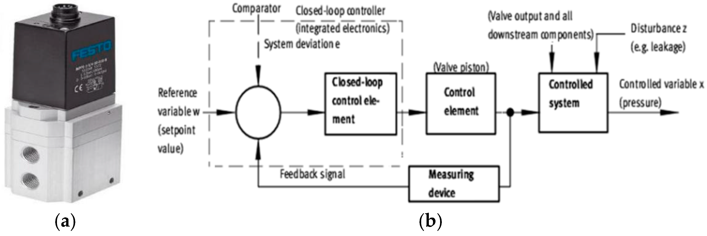
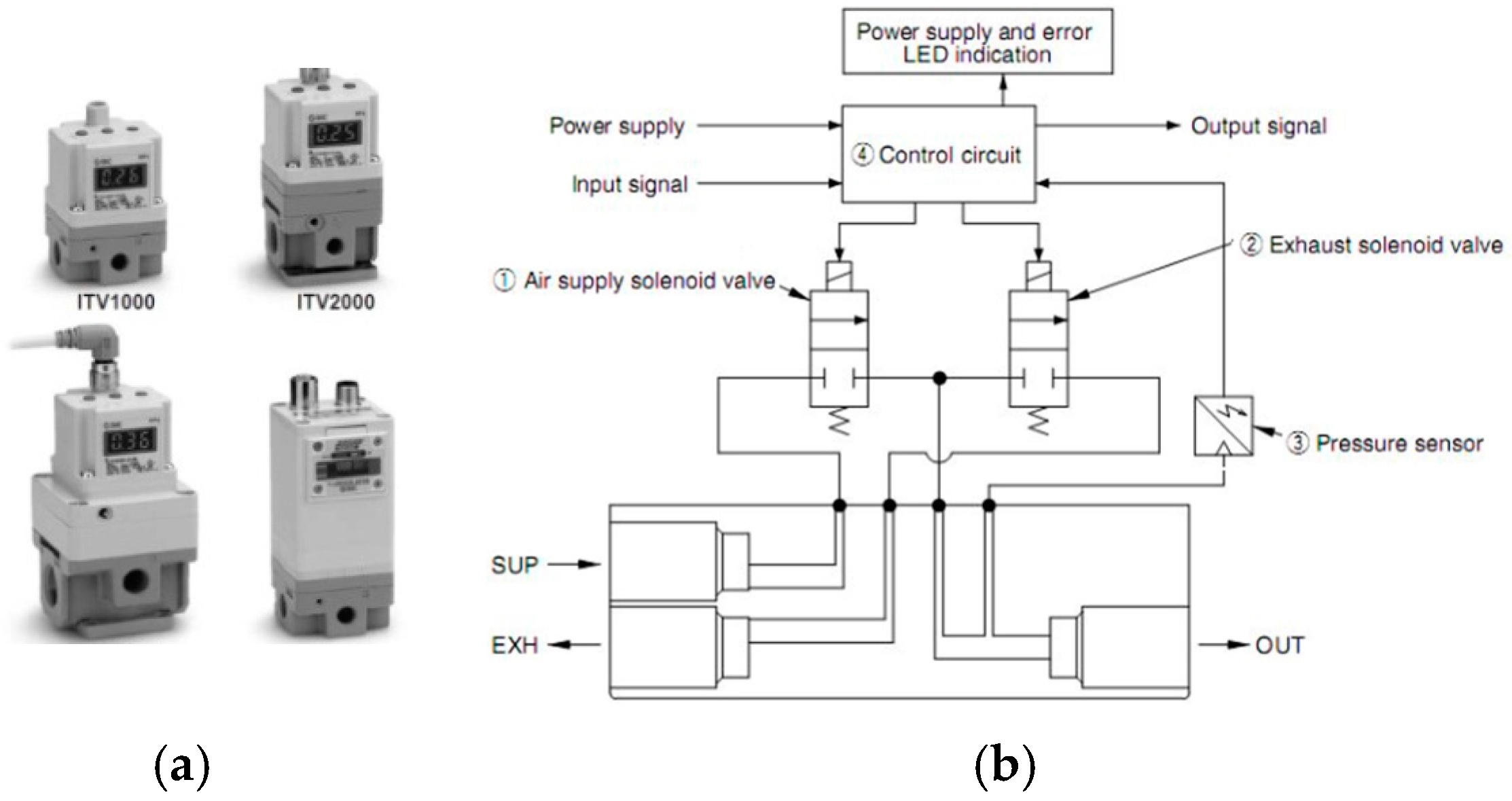
Pneumatic high-speed switch solenoid valve contains many advantages, such as small size, convenience in integrating, anti-pollution, low production costs, and high speed. It is more common for solenoid valves to be the pilot level proportional pressure valves, which are composed of a main valve, a pilot control valve, a digital controller, and a pressure sensor [8,9,10,11]. The pressure sensor is used to detect the pressure of the outlet; it is a closed-loop control, as shown in Figure 1 and Figure 2.
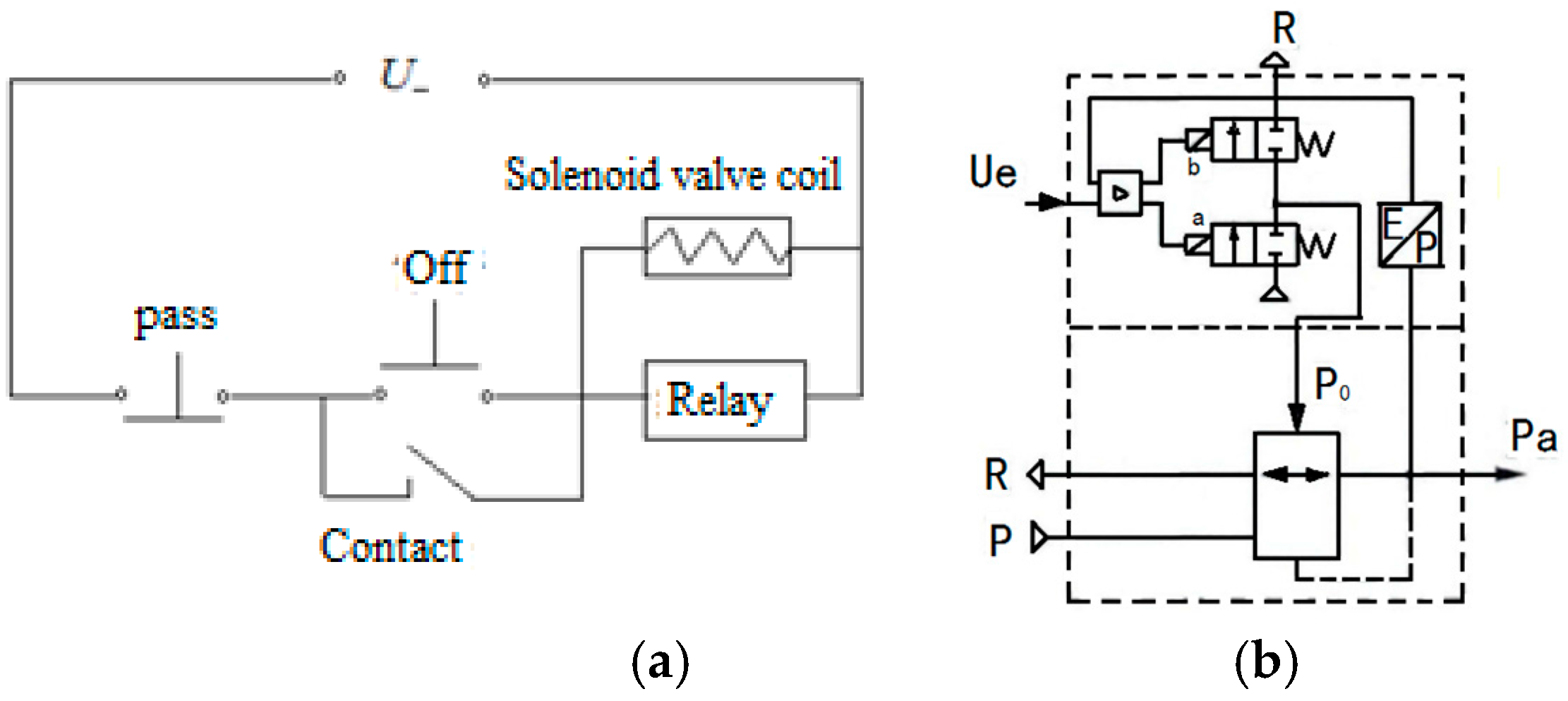
Figure 1 is a modified polyphenylene oxide (MPPE) type electric proportional valve of FESTO Company; Figure 2 is the ITV series valve of SMC Company. There are differences between them, but the principles of both are the same. The square wave signal is controlled by the digital controller output of the electromagnetic pneumatic pressure proportional valve in Figure 3, pilot inlet valve a and exhaust valve b are controlled by square wave signal. When the intake valve a is opened and the exhaust valve b is closed, the output pressure of the pilot valve can be increased, at this time, the active valve core is pushed, and the airflow is increased due to the opening of the opened throttle, the intake port P is connected to the output port Pa.
Switching solenoid pneumatic pressure proportional valve has been studied by a large number of scholars both at home and abroad [12,13,14,15], among whom the most representative research is the Parker P3P-R pneumatic electromagnetic proportional valve conducted by Massimo Sorli [16,17,18]. Parker P3P-R pneumatic solenoid proportional pressure relief valve is a common market in the typical switch solenoid pneumatic pressure proportional valve, as shown in Figure 4a,b. Based on the relationship among the internal parts of the valve, the nonlinear mathematical model of the valve is established, and the dynamic behavior of the valve in the time domain and the frequency domain is studied with numerical analysis and experiments.
Massimo Sorli discovered that when the output pressure of the pressure-reducing valve reaches the preset pressure, the two switches in the control chamber will remain closed, hence there is no excessive energy consumption. However, when the preset pressure changes, it needs to adjust the control valve in the cavity to control the pressure in the valve cavity, frequent opening and closing, and the slow response of the valve, which causes the output frequency response of low pressure valve.
At the same time, the correctness of the mathematical model of Massimo Sorli has been verified, as shown in Figure 4c. Figure 4d is the frequency response of the valve; the results show that the cutoff frequency of the pressure relief valve is 5 Hz. When the valve reaches a frequency of 5 Hz, the pressure chamber will show instantaneous fluctuating pressure and flow and the valve precision will be affected due to the unavoidable limited movement position that is caused by valve position.
Switch electromagnetic pneumatic pressure proportional valve has the advantages of consuming low energy, having a simple structure, low costs, and so on; it has obvious advantages in static pressure regulation. It is insensitive to the rapidly changing pressure signal because it has a low frequency response. At the same time, in the process of pressure regulation, the pressure loss in the control chamber is large, which seriously affects the service life and the reliability of the pressure reducing valve and also restricts the application of switch electromagnetic pneumatic pressure proportional valve.
3. Related Technology Research Progresses
3.1. Numerical Simulation Researches
Pneumatic pressure proportional valve is composed of more complex pneumatic components, including a variety of gas, pneumatic actuators, controllers, and electrical mechanical converters. When analyzing the relationships among various components of the valve, the numerical analysis method is often used, which can predict the performance of the valve, optimize the structure design of the valve, and improve the design efficiency.
Electric mechanical converter will be the proportion of the input current or voltage converted into force or displacement output through the armature of special design. To establish the mathematical model is the key for modeling proportional solenoid valve. Vaughan, N.D., Gamble, J.B. [20] proposed a kind of nonlinear dynamic model of high speed solenoid valve that comprises of a proportional solenoid and the spool, and the model can accurately predict for a given input voltage steady state and dynamic response. The dynamic analysis of the proportional pressure valve is carried out by Dasgupta, K. and Karmakar, R. [21,22]. The dynamic mathematical model of the valve is established, and the flow characteristics of the valve pressure are taken into account to improve the dynamic response characteristics of the pressure valve.
Excepting the direct relationship between the input signal and the output force, the magnetic circuit analysis is a common method thatcan clearly identify each physical quantity and can be used to analyze the static performance of electromagnet. However, the magnetic circuit analysis method cannot describe the dynamic of the electromagnet. In the current study, the researchers tend to limit the method to establish the mathematical model of the electromagnet [23].
For example, Kawase, Y. and Ohachi, Y. [24] analyzed various characteristics of electromagnets by using the finite element method, including resistivity, response speed, and material properties. The finite element model has the advantages of high precision, but it is difficult to use it to find out effective results because there is a large amount of calculation and complex algorithm.
Furthermore, except for the mathematical models, there are semi-empirical modeling methods in which the experimental data are used to fit the nonlinear part of the system [9,20,25,26,27]. In the research of proportional electromagnet circuit, there is the nonlinear induced voltage of the electromagnet motion and in the modeling of a proportional electromagnet, it is hard to find the reasonable approximation of induced voltage.
Many scholars estimated the induced voltage indirectly, that is to say, that they obtained the relationship between the induced voltages by fitting the experimental data. The semi-empirical model is used to study the approximate the induced voltage in XU [25], which is based on the relationship between the output force of the electromagnet and the armature. The linear least square method is used to fit the static experimental results of electromagnetic force, and further obtain the approximate nonlinear induction voltage.
Vaughan [20] used a semi-empirical modeling method to estimate the electromagnet as a pure combination of resistance and nonlinear inductance. The coil current and magnetic flux are calculated by experiment. In Elmer’s Research [26], which is based on the linear relationship between the reciprocal of the equivalent inductance of the coil and the coil current, the linear coefficients are fitted by the experimental data but are less effective. The reason is the ignorance of the influence of the armature displacement on the output force of the proportional electromagnet.
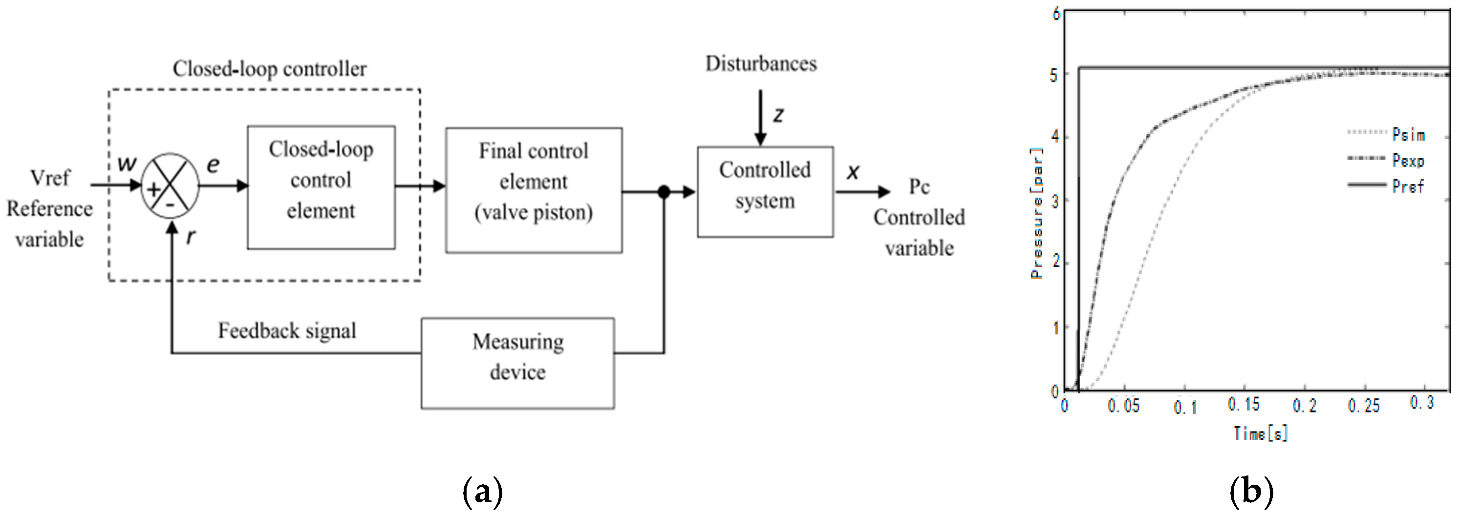
A pneumatic pressure proportional valve for ankle foot orthopedic instruments was studied by Lescano, C.N. [28]. Based on the linear model of the voltage signal and the output pressure, the dynamic response of the pneumatic pressure proportional valve is studied and the open-loop transfer function model of the system is obtained, as shown in Figure 5. Finally, the model is verified by experiments. It can guide the development of driving system of medical instrument gas.
When compared with the finite element method, the semi-empirical modeling method can solve the problem in proportional electromagnet design. However, the non-human factors often affect the accuracy of calculation. Therefore, the researchers often combine finite element methods such as the magnetic circuit structure, material properties, and other physical quantities obtained by the finite element method, thus improving the accuracy of the calculation done by the semi-empirical modeling method.
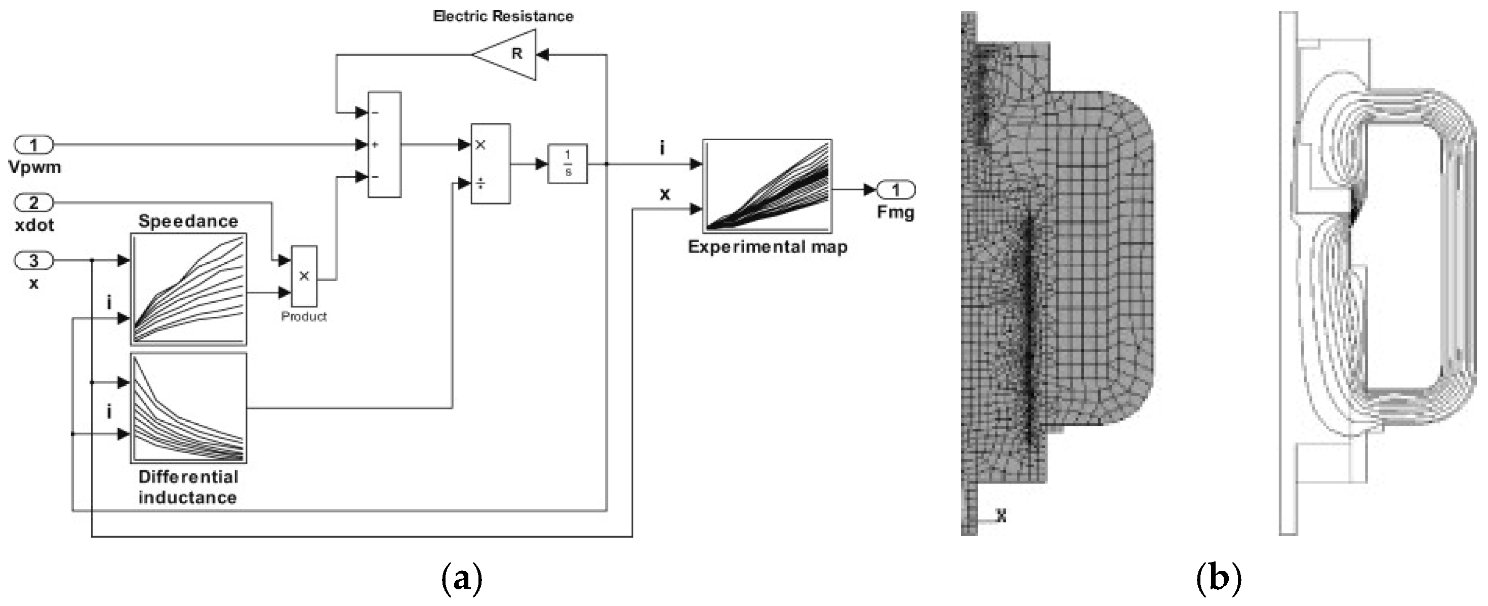
Massimo Sorli [29] used the finite element method and the semi-empirical model to build the mathematical model of the proportional electromagnet, as shown in Figure 6. The data of Speedance and differential inductance are calculated by finite element method. The semi-empirical modeling method, combined with the finite element method, has the advantages of a high accuracy in calculation, simplified calculation, and high efficiency, and is widely used now [27].
3.2. Modeling of Mechanical Structure
The key of structural modeling of pneumatic pressure proportional valve is the modeling of the valve core, in which the force balance is the essence of pneumatic pressure proportional valve. The forces acting on the valve core include friction force, driving force, aerodynamic force, and contact force, and in this paper, various forces will be introduced.
The contact forces also include the spool stroke limit force and the contact force between the valve cores, while the spool stroke limit force is the key to the valve core modeling. The earliest research on the spool stroke limit force is done by Kukulka [15]. They used a simple method to make it easy to travel limit force to a special spring, which is related to the amount of compression. Kukulka determined the relationship between the stiffness and the amount of compression.
Elmer [26] continued the study of Kukulka and found that there was no relationship between the stiffness of the special stiffness and the amount of compression. Based on this, the limit force is simplified as an ordinary spring with an elastic coefficient. It has been pointed out that the contact force between the valve core and the contact material is the hard point in valve core modeling. Massimo Sorli [16] studied this problem and came up with the assumption that the core and contact material are simplified as a spring damping system, and the results are verified by numerical simulation.
The friction force is generated by the contact between the sealing ring and the metal wall of the valve core, and it has been studied by a large number of scholars [30,31]. At present, the most widely used friction model is “Stribeck + viscous friction + Kulun + static friction”:
In the formula, Fc refers to the dynamic friction force of Kulun, Fs refers to the maximum static friction force, b is a viscous friction coefficient, and is Stribeck velocity. The input multiple superimposed flutter signal allows the spool to do a small reciprocating motion, which can effectively eliminates the static friction, thereby eliminating the influence of static friction.
Therefore, the model can be considered without static friction. The viscous friction force is often used for modeling the viscous friction; the absolute value of the spool speed is in proportion to the size of the viscous friction, while the direction of the force is opposite to the direction of the spool [14,19,25]. The viscous friction coefficient is determined by the trial and error method.
Aerodynamic force is the key factor that must be taken into account during the modeling process of the valve core. This is because the changing rate of the aerodynamic force with the displacement of the spool is large, which makes the aerodynamic force enable to produce considerable equivalent stiffness [32]. For this problem, the method of gas resistance is often used, [33]. According to the law of gas flow to the general conversion formula, Piao [34] proposed the concept of air resistance characteristic in series and obtained the conclusion that all of the nonlinear gas resistance has a common series of characteristics. Liu [35] established the model and condition of gas volume, air resistance, and gas resistance in the pneumatic stripping system, and obtained the parameters of air volume and air-flow in pneumatic stripping. In addition, some other scholars have made a preliminary study of the gas resistance and gas content [36].
3.3. Modeling of Gas Flow Characteristics
In terms of the analysis of gas flow characteristics of pneumatic pressure proportional valve, many scholars studied the flow characteristics of the gas passing through the valve port and the thermodynamic properties of the gas in the cavity [32].
By simplifying the complex process of flowing through the valve port of the gas, the process is considered as a constant flow of the nozzle in the research of Venant. If it is assumed that the specific heat of gas is constant, the one-dimensional constant drop flow equation of the ideal gas passing through the contraction nozzle can be presented like:
In the formula, R is the gas constant, Tu is the upper temperature of the gas, m is the gas mass flow through the valve port, Pu and Pd are the downstream pressure of the contraction pipe, and Ct is the critical pressure ratio. For air, Ct = 0.528. When the pressure difference between upstream and downstream is very small as , this excessive gain will enlarge the error in numerical calculation. At the same time when , the gas flow rate approaches 0, and the flow of gas is laminar flow, expressing the gas flow in the quality problems. In order to solve this problem, the following modified formula is needed:
In the formula, is the threshold value which is 0.995~0.999, b is Ct in the formula and ka is the compensation coefficient.
The actual pressure proportional valve orifice is not smooth; it causes the flow loss of the convective gas [37]. Therefore, the actual flow quality is less than the theoretical value of the formula, in order to further improve the flow quality it needs the following formula:
The experimental results showed that the flow coefficient Cd in different types of orifice is different. Perry [37] further suggested that the flow coefficient Cd in the orifice is related to the upstream and downstream pressure ratio, and established the corresponding relation. Reid [38] and Fleischer [39] established the relationship between the flow coefficient and the orifice geometry. The empirical formula of flow coefficient Cd and upstream and downstream pressure ratio is given by Mozer [40]. In addition, some scholars further standardized the calculation of Cd based on the empirical formula of Mozer.
For the study of gas in the cavity of thermodynamics, both domestic and foreign scholars all referred to the ideal gas state equation, the mass continuity equation, and the first law of thermodynamics. The differential equations of pressure and temperature are established, and then the differential equation is simplified. Massimo Sorli [14] calculated the gas in the cavity, and the variation law of pressure in the cavity is given by using the ideal gas state equation. According to the law of adiabatic change, the change of pressure and temperature of the gas in the cavity is obtained according to the change rule in research on Nabi [41]. Cai thought that the heat exchange between the gas and the inner wall of the cavity could be deduced from the energy equation. Richer [38] thought that the gas’s physical changes of entering and leaving the gas chamber are different. It is suggested that when the gas enters the gas chamber, the adiabatic process can be used to estimate the gas. But when the gas flows out of the chamber, it is isothermal.
4. Proportional Controller
4.1. Research on Proportional Controller
Proportional controller and proportional solenoid actuator cooperate with each other to convert the electrical signal (voltage and current) into force proportional to the displacement of the physical output, and their performance often depends on the level of them. The proportional controller is the key of the whole conversion element, which has attracted much attention in both domestic and abroad researches.
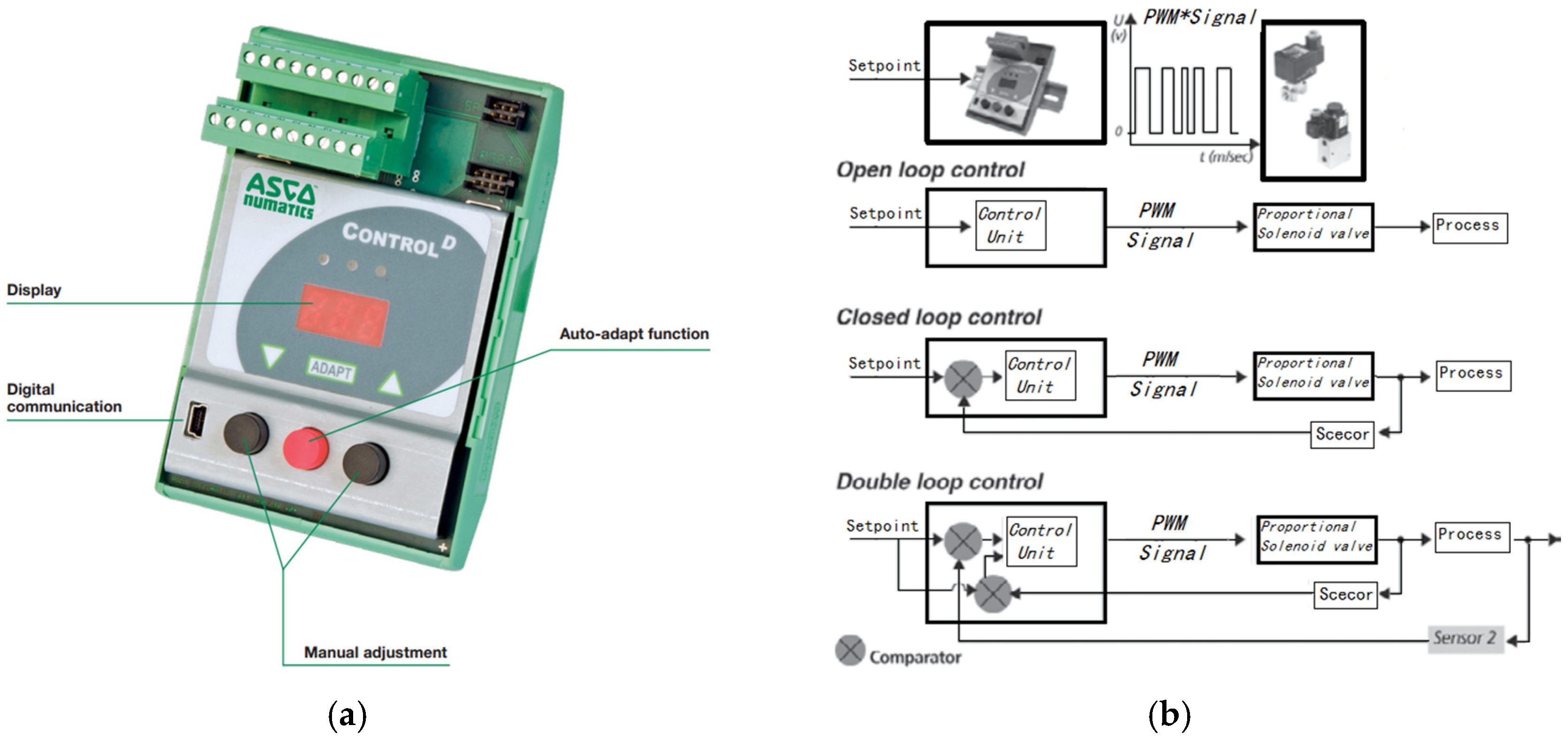
The earliest research on proportional controller is developed in Europe and the United States, and other hydraulic components companies, including Moog, Towler, Vickers, as well as Japan’s oil research company. With the development of pneumatic technology, some pneumatic components manufacturers such as ASCO, SMC, FESTO, etc., also joined the ranks of the proportional controller. Figure 7a is a Control D type proportional NUMATICS’s controller that comprises a power unit, signal processing unit, and a main control unit, according to the input coil current in proportional valve control. It can also be connected to the PC through the mini USB, to support open-loop control, single closed-loop control, and double closed-loop control mode, as shown in Figure 7b.
In the research of component level controller, the power drive circuit is the main research object. The performance of the simulation is poor, the power is low, and it is not easy to integrate. The switch has many advantages, such as high efficiency, small size, and low power consumption.
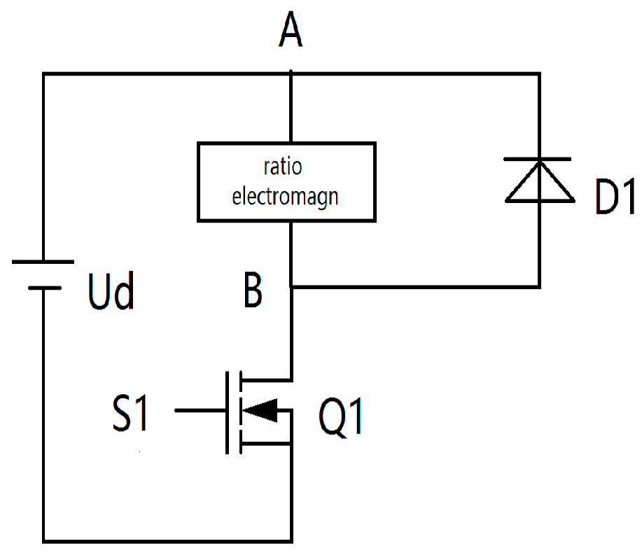
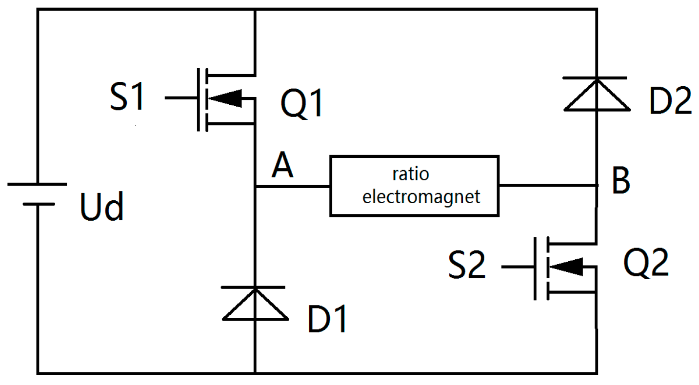
Figure 8 is the topology of the common high side single tube drive circuit. Liu [42,43] wanted to improve the performance of a single drive circuit based on the structure of the proposed “anti-unloading structure”. As shown in Figure 9, the improved structure and the current drop speed are obvious, but it consumes more power. Nie [44] further improved the anti-unloading structure, including the proposed three state modulation proportional electromagnet power anti-unloading mode, the driver, and the realization of arbitrary current control and tracking, which has made great progress. Rexroth proposed the “supercharged driven” method, in which when the current rises, it provides the voltage booster circuit, making the current rapidly rise and improving the driving circuit and the frequency of response. Amirante [45] used the method of “boost drive” in the control of proportional directional valve and put forward the method of increasing current drive, which improved the response time of the control circuit.
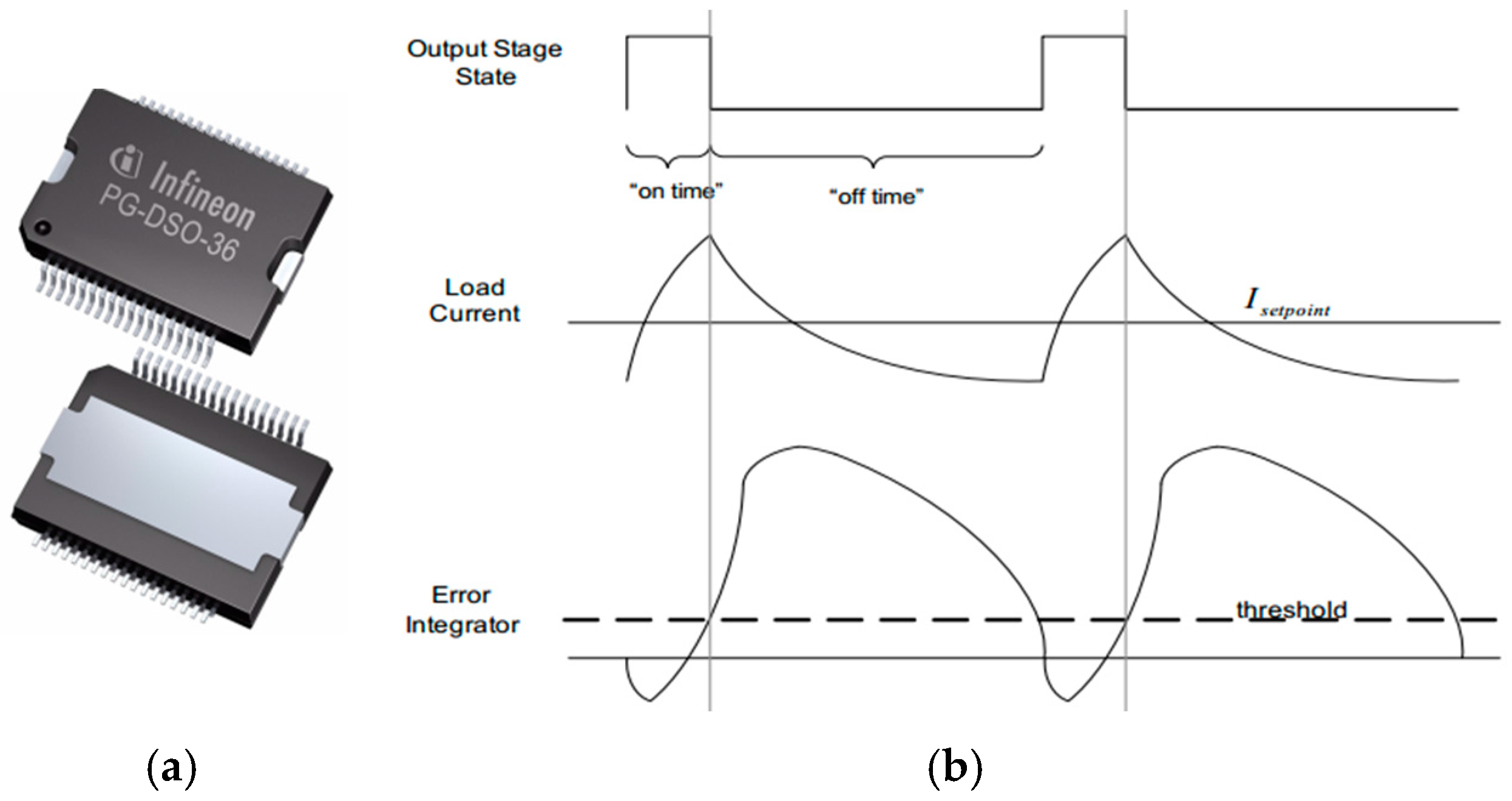
With the development of electronic technology, the integration of the proportional controller is increasing. In addition to the proportional control circuit, there are many independent modules in the control chip, with the advantages of high integration, low cost, and high performance. Figure 10 represents the design of Infineon R & D of proportional solenoid driver chip, which contains the driver transistor, the transistor, and the current recovery resistor. It is composed of a current detection circuit, power driver circuit, and chatter generation circuit with the purpose of realizing the closed-loop control of the coil current. The principle of the control is to adjust the switch of the power tube by dynamic adjustment, so that the coil current reaches the set value. It is widely used in the middle precision proportional control.
When compared with the design of system level and component level proportional controller proportional controller, the former one more focuses on the overall performance of stability, reliability, and universality, and it is the component proportion controller after a certain stage of development of the new design idea. The latter satisfies the reliability level of the proportional controller. As far as the domestic research design is concerned, there are a number of universities and research institutes in China that are only in the experimental stage.
4.2. Research on Control Strategy
The control strategy determines the performance of the pneumatic pressure proportional valve to a great extent, and in the choice of control strategy, it needs to be combined with various components of the function to give full play to the performance of various components. Effective control strategy is the principle in designing the proportional valve. According to proportional pressure relief valve with no pressure electrical feedback, pneumatic pressure proportional valve can be divided into closed-loop control and open-loop control. While the control modes can be divided into sliding mode control and adaptive control.
The current control of solenoid coil is the key of open-loop control design. In the early stage, the coil current is controlled by the P or PI circuit, but it has many disadvantages like poor flexibility and a complicated operation process. Subsequently, the digital controller has been widely used and the coil current control is generally controlled by Proportion Integration Differentiation (PID). Many foreign and domestic scholars have conducted a research on how to improve the accuracy of current control. Ally [46] and Liu [47] studied the control system and since the effect of controller depends on the exact mathematical model of the controlled system, the adaptive parameter method, based on Lyapunov analysis, can compensate the uncertainty of system parameters. Lee, S.R. [48,49] used the least square method to identify the system in real time. Based on this, the controller is designed according to the pole placement.
Based on the embedded model control theory, the embedded model is established in Canuto’s control system [50]. The utility model achieved the purpose of suppressing the disturbance of the current value and the voltage value of the coil, and realized the accurate control. The control strategies are based on the comparison between the current and the current in the coil. But in fact, the increase in the coil temperature leads to changes in coil resistance and furthers the instability of the current in the coil, therefore, some scholars think from the perspective of how to keep the coil resistance constant. Based on the iterative method derived from the fixed point theory, Jung [51,52] estimated the parameters of the coil resistance. Furthermore, the current value of the coil keeps a linear relationship with the duty cycle of the Pulse Width Modulation (PWM) drive signal. Lannone [53] proposed a hardware compensation scheme of coil resistance, the resistance increase of auxiliary circuit real-time measurement coil values, the measured resistance value, and the duty ratio of PWM signal can fix coil working state of the look-up table operation. These methods could effectively improve the control accuracy.
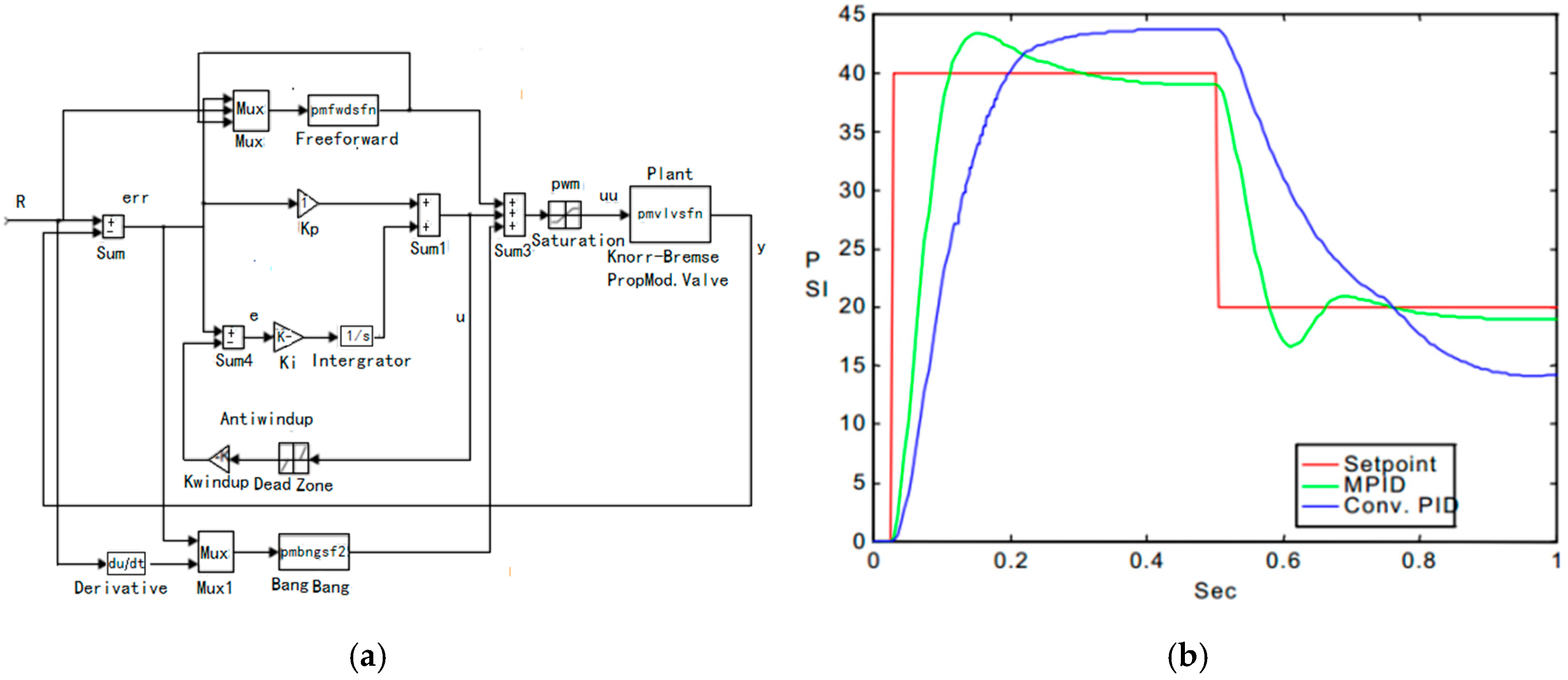
The nonlinear problem in the control of pneumatic pressure proportional valve is caused by the compressibility of the working medium of the gas, and is how to obtain the high precision control. The domestic and foreign famous companies are solved by the closed loop control. PID control is the main control strategy, and the conventional PID control has poor adaptability and low flexibility so it is necessary to improve the PID control. Hamdan [54] believed that the nonlinear problems in the proportional valve have hysteretic characteristics, therefore, they put forward the control strategy of conventional PID, Anti-windup, Bang-bang, and feed forward variable gain control combination, as shown in Figure 11. When compared with the conventional PID control, the control effect of this control strategy is improved obviously, but there still exist many problems such as overshoot and the lack of accuracy.
Wu [55] adopted a generalized predictive control that considered the influence of the change of system stiffness and the setting value, and compensated for the high nonlinearity of the system. As compared with the PID control, the performance of the system using generalized predictive control is improved significantly and the robustness is stronger. Li [56] put forward a variable gain neuron adaptive PID controller to realize the real-time control of piston displacement and the valve controlled cylinder pneumatic position servo control system. This method does not require the accurate modeling of the system. The controller has a simple structure, convenient design, and steady performance.
PWM has been successfully applied to pneumatic switch control [57,58,59], and has become the most extensive and effective control method, and it can improve the regulating precision of the regulating valve and reduce the power consumption. After turning on the solenoid valve, the circuit is switched to PWM operation at once. The frequency of the PWM pulse is much larger than the response frequency of the solenoid valve, so the time of the pulse flow on the coil is averaged to form a sustainable current. The PWM drive mode also has the advantages of simple circuit structure, small size, and low energy consumption, but the problem of slow opening and closing time of the pilot valve is widespread [60,61,62]. In recent years, with the development of integrated circuits, insulated gate bipolar transistors (IGBT) have gradually replaced Metal-Oxide-Semiconductor Field-Effect Transistor (MOSFET) and Bipolar junction transistor (BJT) devices in PWM drive control of switching valves [63].
By measuring the input and output information, the adaptive control can adjust the air quantity according to the dynamic characteristics of the controlled object and the system error, which means to adjust the motion law of the controller so that the control performance of the system can be maintain to optimally [64]. Wang [65] controlled the pressure in the gas tank, and established the three-order controlled auto-regressive moving average model. For the state variables in the model and the parameters of the model, Wang used the Calman filtering method and the recursive least squares algorithm with a recursive factor.
In order to make the model more universal, Wang has also designed a linear two-time self-tuning pressure regulator, which has a better pressure control effect. In order to reduce the overshoot of the system and improve the precision of the system, Pipat Chaewieang [66] designed a generalized predictive control method to control the load pressure, and Wang also used a similar solution in the calculation process to achieve the desired objectives. Steven Lambeck [67] presented an exact linearization control method for the nonlinear dynamic model based on pneumatic pressure proportional valve. It can adapt great to the volume of gas in the valve chamber, which improves the output linearity of the pneumatic pressure proportional valve.
The influence of friction force on the pressure pneumatic pressure proportional valve control system is nonlinear. Regarding the study of friction, the general approach is to compensate the friction force, especially in the spool type pressure pneumatic pressure proportional valve. The influence of the uncertainty of the large friction parameters on the nonlinear robust control has been studied by Shen [68], and the corresponding control method has been proposed. In the Arkan’s [69] study of friction compensation, in order to realize a better linearity in the input and output, the discrete filtering method is used and the Luenberger observer is used to realize the accurate displacement observation, so as to compensate the influence of the friction force on the control system. Tore [70] analyzed the motion of the valve core, including the amplitude, pulse width, and the fundamental frequency, and put forward a reasonable superposition of the flutter signal that can be compensated for the impact of friction on the control system. Except for the compensating friction, there are other ways to reduce friction. For example, the air bearing has the advantages such as clean, small friction, and etc. Kayihan [69] used air bearing to reduce the friction of spool movement. However, it is complex and costly to apply the air bearing pressure pneumatic pressure proportional valve structure.
5. Conclusions
As the people’s awareness of environmental protection has enhanced, green clean energy is developing rapidly. Compressed air has the unique advantages regarding the energy storage and transmission. It has been widely favored, and pneumatic components have also been developed rapidly. For electric proportional valve pressure, to complete the precise regulation is no longer the only goal, it aims to achieve the electrical integration and integration of the development direction of the composite. “PLC + sensor + pneumatic components” has become a typical control system. The pneumatic components or mechanisms with different functions form new integrated components or mechanisms with additional functions are to make them composite and integrated. Composite integration can shorten the design cycle, reduce wiring, piping, and components, while reducing the impact and debugging time, thus improving work efficiency has become the development trend of electric proportional valves.
High-pressure can improve the dynamic characteristics, the hardness, and the response speed of the pneumatic system, and also realize the miniaturization and high speed of pneumatic components. With the maturation of compressed gases, especially energy density devices, such as new fuel cell vehicles, can effectively solve these problems, such as stringent energy storage, volume ratio, and high-pressure. In addition, the pressure reduction can also reduce the volume of the actuating element, and the corresponding auxiliary elements such as filters and electromagnetic valves. Pressure reducing valves are correspondingly reduced in size. Thus, the cost, installation space, and resources are also reduced. In the future, the development of high-pressure pneumatic components, energy saving and safety research of components and systems will be the main research field of the electrical pneumatic pressure proportional valve.
Moreover, regarding the research and application of the electric-pneumatic pressure proportional valves, it is necessary to meet the following requirements:
5.1. Oil-Free
The mechanical components in the pneumatic system need to be lubricated so that the oil sprayer in the system is indispensable. In the pneumatic system, there is no return pipeline for oil mist recovery, and the exhaust gas causes pollution to the environment. The development of the non-oil system is required in the development of the electric-pneumatic pressure proportional valves. With the extensive research of self-lubrication special material and gas film lubrication, its unique lubricity can be applied to an oil-free system, which provides the idea for oil-free system [71,72,73,74,75,76].
5.2. Miniaturization and Light-Weight
With the miniaturization of mechanical components and mechanical devices, the miniaturization of pneumatic components, pneumatic auxiliary components, and control elements is becoming much higher. The miniaturization and light-weight of pneumatic components consume less energy and cost, and can thus reduce the overall cost of the system. At present, most of the components are made of aluminum alloy and new plastic materials and they are made of ultra-thin, ultra short, and ultra-small parts. But as the demand of miniaturization keeps growing, it is necessary to explore new methods of miniaturization design.
5.3. Energy Saving
The manufacturing industry in all countries focuses on energy saving. While the energy saving of pneumatic technology can be carried out in two ways: reducing the consumption of gas and reducing the power of the system. Reducing power consumption as an important aspect of energy saving aims to develop a variety of small power solenoid valves and the power of less than 2 W solenoid valve is popular. Reducing the gas consumption aims to reduce the power consumption of the compressor thus to achieve the effect of saving energy.
Acknowledgments
The research is funded by Grants (51575020, 51675020) of the National Natural Science Foundation of China and Open Foundation of the State Key Laboratory of Fluid Power and Mechatronic Systems.
Author Contributions
Fangwei Ning was responsible for consulting the literature and drafting the paper. Yan Shi, Maolin Cai, Yixuan Wang, Weiqing Xu contributed to directing the thesis.
Conflicts of Interest
The authors declare no conflict of interest.
References
- Shearer, J.L. Study of Pneumatic Process in the Continuous Control of Motion with Compressed Air-I. Trans. ASME 1956, 2, 233–242. [Google Scholar]
- Burrows, C.R.; Webb, C.R. Simulation of an On-Off Pneumatic Servomechanism. Proc. Inst. Mech. Eng. 1967, 182, 631–642. [Google Scholar] [CrossRef]
- Burrows, C.R.; Webb, C.R. Further Study of a Low-Pressure on-off Pneumatic Servomechanism. Proc. Inst. Mech. Eng. 1969, 184, 849–858. [Google Scholar] [CrossRef]
- Xu, H. Theory Analysis and Study of Control Method of Pneumatic-Hydraulic Combination Control Position System. Ph.D. Thesis, Harbin Institute of Technology, Harbin, China, 1 April 2001. (In Chinese). [Google Scholar]
- Ioannidis, I.; Nguyen, T. Microcomputer-Controlled Servo-Pneumatic Drives. In Proceedings of the 7th International Fluid Power Symposium, Bath, UK, 16–18 September 1986; pp. 155–164. [Google Scholar]
- Liu, S.; Bobrow, J.E. An Analysis of a Pneumatic Servo System and Its Application to a Computer-Controlled Robot. J. Dyn. Syst. Meas. Control 1988, 110, 228–235. [Google Scholar] [CrossRef]
- Lai, J.Y.; Menq, C.H.; Singh, R. Accurate Position Control of a Pneumatic Actuator. ASME J. Dyn. Syst. Meas. Control 1990, 112, 734–739. [Google Scholar] [CrossRef]
- Numatics. Proportional Technology Precise Control of Pressure and Flow; Numatics: Norwich, MI, USA, 2012; Available online: www.numatics.com (accessed on 8 July 2017).
- Matrix. Panel Mounting Electronic Pressure Regulator. 2011. Available online: http://www.matrix.to.it/matrix2005/business3.aspid=14&id2=7&idbarea2=17 (accessed on 8 July 2017).
- Proportion Air. QPV&MPV Proportional Pressure Control Valves. 2011. Available online: http://www.proportionair.com (accessed on 8 July 2017).
- Festo. Proportional Pressure Regulators VPPE without Display; Festo: Shanghai, China, 2010; Available online: http://www.festo.com.cn (accessed on 8 July 2017).
- Belforte, G. Design of a new pressure regulator with electronic control: Friction force analysis. In Proceedings of the International Conference on Functional Programming (ICFP’2005), Hangzhou, China, 5–8 April 2005; Available online: http://porto.polito.it/1419478/ (accessed on 17 October 2017).
- Szente, V.; Vad, J.; Lorant, G.; Fries, A. Computational and experimental investigation on dynamics of electric braking systems. In Proceedings of the Scandinavian. International Conference on Fluid Power, Linkoping, Sweden, 30 May–1 June 2001. [Google Scholar]
- Sorli, M.; Figliolini, G.; Pastorelli, S. Dynamic model and experimental investigation of a pneumatic proportional pressure valve. IEEE ASME Trans. Mechatron. 2004, 9, 78–86. [Google Scholar] [CrossRef]
- Sorli, M.; Figliolini, G.; Almondo, A. Mechatronic Model and Experimental Validation of a Pneumatic Servo-Solenoid Valve. J. Dyn. Syst. Meas. Control. 2010, 132, 626–634. [Google Scholar] [CrossRef]
- Ahn, K.; Yokota, S. Intelligent switching control of pneumatic actuator using on/off solenoid valves. Mechatronics 2005, 15, 683–702. [Google Scholar] [CrossRef]
- Passarini, L.C.; Nakajima, R.P. Development of a high-speed solenoid valve: An investigation of the importance of the armature mass on the dynamic response. J. Braz. Soc. Mech. Sci. Eng. 2003, 25, 1143–1147. [Google Scholar] [CrossRef]
- Kajima, T.; Kawamura, Y. Development of a high-speed solenoid valve: Investigation of solenoids. IEEE Trans. Ind. Electron. 2002, 42, 1–8. [Google Scholar] [CrossRef]
- SMC. E-P Hyregvyl; SMC: Changzhou, China, 2010; Available online: http://www.smcworld.com/ (accessed on 8 July 2017).
- Vaughan, N.D.; Gamble, J.B. The Modeling and Simulation of a Proportional Solenoid Valve. J. Dyn. Syst. Meas. Control 1996, 118, 120–125. [Google Scholar] [CrossRef]
- Dasgupta, K.; Karmakar, R. Modelling and dynamics of single-stage pressure relief valve with directional damping. Simul. Model. Pract. Theory 2002, 10, 51–67. [Google Scholar] [CrossRef]
- Dasgupta, K.; Watton, J. Dynamic analysis of proportional solenoid controlled piloted relief valve by bondgraph. Simul. Model. Pract. Theory 2005, 13, 21–38. [Google Scholar] [CrossRef]
- Lequesne, B.P. Finite-element analysis of a constant-force solenoid for fluid flow control. IEEE Trans. Ind. Appl. 1988, 24, 574–581. [Google Scholar] [CrossRef]
- Kawase, Y.; Ohachi, Y. Dynamic analysis of automotive solenoid valve using finite element method. IEEE Trans. Magn. 1991, 27, 39–42. [Google Scholar] [CrossRef]
- Xu, Y.; Jones, B. A simple means of predicting the dynamic response of electromagnetic actuators. Mechatronics 1997, 7, 589–598. [Google Scholar] [CrossRef]
- Elmer, K.F.; Gentle, C.R. A parsimonious model for the proportional control valve. J. Mech. Eng. Sci. 2001, 215, 1357–1363. [Google Scholar] [CrossRef]
- Gaeta, A.D.; Glielmo, L.; Diglio, V. Modeling of an Electromechanical Engine Valve Actuator Based on a Hybrid Analytical-FEM Approach. IEEE ASME Trans. Mechatron. 2008, 13, 625–637. [Google Scholar] [CrossRef]
- Lescano, C.N.; Rodrigo, S.E.; Herrera, C.V. Dynamic Response of a Pneumatic Pressure Valve Applied to the Design of an Actuation System in Assistive Robotics. IFMBE Proc. 2015, 49, 952–955. [Google Scholar]
- Kukulka, D.J.; Benzoni, A.; Mollendorf, J.C. Digital Simulation of a Pneumatic Pressure Regulator. Soc. Model. Simul. Int. 1994, 63, 252–266. [Google Scholar] [CrossRef]
- Armstrong, H.B.; Dupont, E.; Canudas, W.C. A Survey of Models, analysis tools and Compensation Methods for the Control of Machines with Friction. Automatica 1994, 307, 1083–1138. [Google Scholar] [CrossRef]
- Canudas, D.W.C.; Olsson, H.; Astron, K.J. A New Model for Control of Systems with Friction. IEEE Trans. Autom. Control 1995, 40, 419–425. [Google Scholar] [CrossRef]
- Beater, P. Pneumatic Drives: System Design, Modelling and Control; Springer: Berlin, Germany, 2007. [Google Scholar] [CrossRef]
- Idelchik, I.E.; Fried, E. Handbook of Hydraulic Resistance; Hemisphere Publishing: New York, NY, USA, 1986. [Google Scholar]
- Andersen, B.W.; Binder, R.C. The Analysis and Design of Pneumatic Systems. J. Appl. Mech. 1967, 34, 1055. [Google Scholar] [CrossRef]
- Liu, M.W.; Zhang, L.F. Application of Pneumatic Capacity Pneumatic Inductance and Pneumatic Resistance on Pneumatic Peeling-off. Chin. Hydraul. Pneum. 2006, 2006, 14–15. (In Chinese) [Google Scholar]
- Xu, Z.P.; Wang, X.Y.; Pi, Y.J. Numerical Simulation of PPRV Based on Pneumatic Bridge and Control Networks. In Proceedings of the Fifth Fluid Power Transmission and control, Hangzhou, China, 3–5 April 2007; pp. 961–964. [Google Scholar]
- Perry, J.A. Critical Flow through Sharp-edged Orifices. Trans. ASME 1949, 71, 757–764. [Google Scholar]
- Reid, J.; Stewart, C.D. A review of critical flow nozzles for the mass flow measurement of gases. In Proceedings of the 2nd International Symposium on Fluid Control Measurement Mechanics and Flow Visualization, Sheffield, UK, 5–9 September 1988; pp. 454–457. [Google Scholar]
- Fleischer, H. Manual of Pneumatic System Operation; McGraw-Hill: New York, NY, USA, 1995. [Google Scholar]
- Szente, V.; Mózer, Z.; Ákos, T. Experimental investigation on pneumatic components. In Proceedings of the 12th International Conference on Modelling Fluid Flow, Budapest, Hungary, 3–6 September 2003. [Google Scholar]
- Nabi, A.; Wacholder, E.; Dayan, J. Dynamic Model for a Dome-Loaded Pressure Regulator. J. Dyn. Syst. Meas. Control 2000, 122, 290–297. [Google Scholar] [CrossRef]
- High, A.; Riche, E.; Hurmuzlu, Y. A High Performance Pneumatic Force Actuator System Part 1—Nonlinear Mathematical Model. J. Dyn. Syst. Meas. Control 2001, 122, 416–425. [Google Scholar]
- Liu, X.H. Optimization of Static Characteristics of Proportional Control Amplifier and Proportional electro Magnet. Hangzhou Zhejiang Univ. 1987, 17, 126–225. [Google Scholar]
- Nie, Y. Research on the Key Technology of A New Programmable Electro Hydraulic Proportional Controller. Ph.D. Thesis, Zhejiang University, Hangzhou, China, 2017. Available online: http://cdmd.cnki.com.cn/Article/CDMD-10335-1011068969.htm (accessed on 8 July 2017).
- Amirante, R.; Innone, A.; Catalano, L.A. Boosted PWM Open Loop Control of Hydraulic Proportional Valves. Energy Convers. Manag. 2008, 49, 2225–2236. [Google Scholar] [CrossRef]
- Liu, R.; Alleyne, A. Nonlinear Force/Pressure Tracking of an Electro-Hydraulic Actuator. J. Dyn. Syst. Meas. Control 2000, 122, 232–237. [Google Scholar] [CrossRef]
- Alleyne, A.; Liu, R. A simplified approach to force control for electro-hydraulic systems. Control Eng. Pract. 2000, 8, 1347–1356. [Google Scholar] [CrossRef]
- Lee, S.R.; Srinivasan, K. On-Line Identification of Process Models in Closed Loop Material Testing. In Proceedings of the American Control Conference, Atlanta, GA, USA, 15–17 June 1988; pp. 1909–1916. [Google Scholar]
- Lee, S.R.; Srinivasan, K. Self-Tuning Control Application to Closed-Loop Servohydraulic Material Testing. J. Dyn. Syst. Meas. Control 1990, 112, 680–689. [Google Scholar] [CrossRef]
- Canuto, E.; Acuria-Bravo, W.; Agostani, M.; Bonadei, M. Digital current regulator for proportional electro-hydraulic valves with unknown disturbance rejection. ISA Trans. 2014, 53, 909–919. [Google Scholar] [CrossRef] [PubMed]
- Jung, H.; Hwang, J.; Yoon, P.; Kim, J. Robust Solenoid Current Control for EHB. Math. Oper. Res. 2005, 28, 11–14. [Google Scholar]
- Jung, H.G.; Hwang, J.Y.; Yoon, P.J.; Kim, J. Resistance estimation of a pwm-driven solenoid. Int. J. Automot. Technol. 2007, 8, 249–258. [Google Scholar]
- Iannone, C.A.; Turner, K.W. Apparatus and Method for Monitoring and Compensating for Variation in Solenoid Resistance during Use. U.S. Patent 7,054,772, 30 May 2006. [Google Scholar]
- Hamdan, M.; Gao, Z. A novel PID Controller for Pneumatic Proportional Valves with Hysteresis. In Proceedings of the 2000 Conference Record of the IEEE Industry Applications Conference, Rome, Italy, 8–12 October 2000; Volume 2, pp. 1198–1201. [Google Scholar]
- Wu, G.; Sepehri, N.; Ziaei, K. Design of hydraulic force control system using a generalized predictive control algorithm. IEE Proc. Control Theory Appl. 1998, 145, 428–436. [Google Scholar] [CrossRef]
- Li, B.; Wu, J.B.; Du, J.M. Research on Control Strategy of High-pressure Pneumatic Servo Position System. Hydraul. Pneum. Seals 2002, 2, 5–7. [Google Scholar]
- Zhou, H. The technology of pneumatic proportional control and its application. Chin. Hydraul. Pneum. 1999, 3, 1–3. [Google Scholar]
- Liu, X.; Jia, Q.; Liu, G.B. The Study on Controlling the Position of Air Cylinder by Electropneumatic Proportional Valve. Mech. Eng. 2002, 6, 19–25. [Google Scholar]
- Han, J.H.; Zhang, H.X. The pneumatic proportional servo control technology and its application. Mach. Tools Hydraul. 2001, 1, 3–7. [Google Scholar]
- Li, J.X.; Yuan, G.Q. Study of PWM controller based on AT 89C2051 single-chip micro-controller. J. Zhejiang Univ. Technol. 2000, 5, 419–425. [Google Scholar]
- Zhou, X.; Shan, X.H.; Chen, L. The study of the digital proportional valve control system. Mech. Electr. Eng. Technol. 1997, 2, 51–52. [Google Scholar]
- Yu, L. Methods to generate pulse-width modulation wave with single-chip microprocessor. J. Fujian Agric. Univ. 2001, 17, 332–347. [Google Scholar]
- Tian, J. Developing PWM Signal Genevator for High Speed On-off Valve. J. Civ. Aviat. Univ. China 2003, 6, 256–301. [Google Scholar]
- Topçu, E.E.; Yüksel, İ.; Kamış, Z. Development of electro-pneumatic fast switching valve and investigation of its characteristics. Mechatronics 2006, 16, 365–378. [Google Scholar] [CrossRef]
- Wang, X.S.; Cheng, Y.H.; Peng, G.Z. Modeling and self-tuning pressure regulator design for pneumatic-pressure–load systems. Control Eng. Pract. 2007, 15, 1161–1168. [Google Scholar] [CrossRef]
- Chaewieang, P.; Sirisantisamrit, K.; Thepmanee, T. Pressure control of pneumatic-pressure-load system using generalized predictive controller. In Proceedings of the IEEE International Conference on Mechatronics and Automation, Takamatsu, Japan, 5–8 August 2008; pp. 788–791. [Google Scholar]
- Lambeck, S.; Busch, C. Exact Linearization Control for a pneumatic proportional pressure control valve. In Proceedings of the IEEE International Conference on Control and Automation, Xiamen, China, 9–11 June 2010; pp. 22–27. [Google Scholar]
- Shen, T.; Tamura, K.; Kaminaga, H.; Henmi, N.; Nakazawa, T. Robust Nonlinear Control of Parametric Uncertain Systems with Unknown Friction and Its Application to a Pneumatic Control Valve. J. Dyn. Syst. Meas. Control 2000, 122, 257–262. [Google Scholar] [CrossRef]
- Kayihan, A.; Francis, J.D. Friction compensation for a process control valve. Control Eng. Pract. 2000, 8, 799–812. [Google Scholar] [CrossRef]
- Hägglund, T. A friction compensator for pneumatic control valves. J. Process Control 2002, 12, 897–904. [Google Scholar] [CrossRef]
- Shi, Y.; Wang, Y.; Cai, M.; Zhang, B.; Zhu, J. Study on the Aviation Oxygen Supply System Based on a Mechanical Ventilation Model. Chin. J. Aeronaut. 2017. accepted. [Google Scholar]
- Ren, S.; Shi, Y.; Cai, M.; Xu, W. Influence of secretion on airflow dynamics of mechanical ventilated respiratory system. IEEE/ACM Trans. Comput. Biol. Bioinform. 2017, 99, 1. [Google Scholar] [CrossRef] [PubMed]
- Ren, S.; Cai, M.; Shi, Y.; Xu, W.; Zhang, X.D. Influence of Bronchial Diameter Change on the airflow dynamics Based on a Pressure-controlled Ventilation System. Int. J. Numer. Methods Biomed. Eng. 2017. [Google Scholar] [CrossRef] [PubMed]
- Shi, Y.; Zhang, B.; Cai, M.; Xu, W. Coupling Effect of Double Lungs on a VCV Ventilator with Automatic Secretion Clearance Function. IEEE/ACM Trans. Comput. Biol. Bioinform. 2017, 99, 1. [Google Scholar] [CrossRef] [PubMed]
- Shi, Y.; Zhang, B.; Cai, M.; Zhang, D. Numerical Simulation of volume-controlled mechanical ventilated respiratory system with two different lungs. Int. J. Numer. Methods Biomed. Eng. 2016, 33, 2852. [Google Scholar] [CrossRef] [PubMed]
- Niu, J.; Shi, Y.; Cai, M.; Cao, Z.; Wang, D.; Zhang, Z.; Zhang, D.X. Detection of Sputum by Interpreting the Time-frequency Distribution of Respiratory Sound Signal Using Image Processing Techniques. Bioinformatics 2017. [Google Scholar] [CrossRef]
Figure 1.
FESTO proportional valve. (a) FESTO pneumatic pressure proportional valve modified polyphenylene oxide (MPPE); (b) FESTO MPPE proportional valve working principle diagram.
Figure 1.
FESTO proportional valve. (a) FESTO pneumatic pressure proportional valve modified polyphenylene oxide (MPPE); (b) FESTO MPPE proportional valve working principle diagram.

Figure 2.
SMC pneumatic pressure proportional valve. (a) SMC ITV series electric proportional valve; (b) SMC ITV electric proportional valve working principle diagram.
Figure 2.
SMC pneumatic pressure proportional valve. (a) SMC ITV series electric proportional valve; (b) SMC ITV electric proportional valve working principle diagram.

Figure 3.
Switch solenoid pneumatic pressure proportional valve. (a) Solenoid valve control circuit diagram; (b) Schematic diagram of switch solenoid valve.
Figure 3.
Switch solenoid pneumatic pressure proportional valve. (a) Solenoid valve control circuit diagram; (b) Schematic diagram of switch solenoid valve.

Figure 4.
ParkerP3P-R pneumatic solenoid pneumatic pressure proportional valve. (a) P3P-R pneumatic solenoid pneumatic pressure proportional valve; (b) Schematic of P arkerP3P-R pneumatic solenoid; (c) Sinusoidal tracking signal; (d) Frequency response.
Figure 4.
ParkerP3P-R pneumatic solenoid pneumatic pressure proportional valve. (a) P3P-R pneumatic solenoid pneumatic pressure proportional valve; (b) Schematic of P arkerP3P-R pneumatic solenoid; (c) Sinusoidal tracking signal; (d) Frequency response.

Figure 5.
Linear model of Lescano, C.N. voltage signal and output pressure. (a) Schematic of pneumatic pressure proportional valve circuit; (b) Comparison of model validation.
Figure 5.
Linear model of Lescano, C.N. voltage signal and output pressure. (a) Schematic of pneumatic pressure proportional valve circuit; (b) Comparison of model validation.

Figure 6.
Electromagnet model of Massimo Sorli. (a) Electromagnet model; (b) Finite element model.

Figure 7.
NUMATICS D Control proportional controller. (a) Control type proportional controller; (b) Schematic diagram of control mode.
Figure 7.
NUMATICS D Control proportional controller. (a) Control type proportional controller; (b) Schematic diagram of control mode.

Figure 8.
High side single tube driving circuit.

Figure 9.
Anti unloading driving structure.

Figure 10.
Infineon Company’s proportional solenoid drive chip. (a) Driver chip; (b) Schematic diagram of current control.
Figure 10.
Infineon Company’s proportional solenoid drive chip. (a) Driver chip; (b) Schematic diagram of current control.

Figure 11.
ModifiedProportion Integration Differentiation (MPID) control strategy of Hamdan. (a) Schematic diagram of control strategy; (b) Comparison of conventional PID and MPID.
Figure 11.
ModifiedProportion Integration Differentiation (MPID) control strategy of Hamdan. (a) Schematic diagram of control strategy; (b) Comparison of conventional PID and MPID.

© 2017 by the authors. Licensee MDPI, Basel, Switzerland. This article is an open access article distributed under the terms and conditions of the Creative Commons Attribution (CC BY) license (http://creativecommons.org/licenses/by/4.0/).
Share and Cite
MDPI and ACS Style
Ning, F.; Shi, Y.; Cai, M.; Wang, Y.; Xu, W. Research Progress of Related Technologies of Electric-Pneumatic Pressure Proportional Valves. Appl. Sci. 2017, 7, 1074. https://0-doi-org.brum.beds.ac.uk/10.3390/app7101074
AMA Style
Ning F, Shi Y, Cai M, Wang Y, Xu W. Research Progress of Related Technologies of Electric-Pneumatic Pressure Proportional Valves. Applied Sciences. 2017; 7(10):1074. https://0-doi-org.brum.beds.ac.uk/10.3390/app7101074
Chicago/Turabian StyleNing, Fangwei, Yan Shi, Maolin Cai, Yixuan Wang, and Weiqing Xu. 2017. "Research Progress of Related Technologies of Electric-Pneumatic Pressure Proportional Valves" Applied Sciences 7, no. 10: 1074. https://0-doi-org.brum.beds.ac.uk/10.3390/app7101074
Note that from the first issue of 2016, this journal uses article numbers instead of page numbers. See further details here.