Laboratory and On-Site Tests for Rapid Runway Repair
by
 , ,
, ,
Federico Leonelli
1, 
Paola Di Mascio
1 ,
,
Antonello Germinario
2,
Francesco Picarella
3,
Laura Moretti
1,* ,
,
Mauro Cassata
3 and
Alberto De Rubeis
4 1
Department of Civil, Constructional and Environmental Engineering, Sapienza University of Rome, Via Eudossiana 18, 00184 Rome, Italy
2
Laboratorio Principale Prove e Sperimentazioni (ITAF Infrastructure Department), Viale di Marino snc, 00043 Ciampino, Italy
3
2 Reparto Genio A.M. (ITAF Infrastructure Department), Viale di Marino snc, 00043 Ciampino, Italy
4
Servizio Infrastrutture A.M. (Chief of ITAF Infrastructure Department), Viale dell’Università 4, 00185 Rome, Italy
*
Author to whom correspondence should be addressed.
Appl. Sci. 2017, 7(11), 1192; https://0-doi-org.brum.beds.ac.uk/10.3390/app7111192
Submission received: 15 October 2017
/
Revised: 8 November 2017
/
Accepted: 16 November 2017
/
Published: 19 November 2017
(This article belongs to the Special Issue Advanced Asphalt Materials and Paving Technologies)
Abstract
:Featured Application
The results of this study offer a broad vision for the rapid runway repair, giving a useful quantitative and objective tool for airport management body; moreover, they could be applied also for road pavements.
Abstract
The attention to rapid pavement repair has grown fast in recent decades: this topic is strategic for the airport management process for civil purposes and peacekeeping missions. This work presents the results of laboratory and on-site tests for rapid runway repair, in order to analyse and compare technical and mechanical performances of 12 different materials currently used in airport. The study focuses on site repairs, a technique adopted most frequently than repairs with modular elements. After describing mechanical and physical properties of the examined materials (2 bituminous emulsions, 5 cement mortars, 4 cold bituminous mixtures and 1 expanding resin), the study presents the results of carried out mechanical tests. The results demonstrate that the best performing material is a one-component fast setting and hardening cement mortar with graded aggregates. This material allows the runway reopening 6 h after the work. A cold bituminous mixture (bicomponent premixed cold asphalt with water as catalyst) and the ordinary cement concrete allow the reopening to traffic after 18 h, but both ensure a lower service life (1000 coverages) than the cement mortar (10,000 coverages). The obtained results include important information both laboratory level and field, and they could be used by airport management bodies and road agencies when scheduling and evaluating pavement repairs.
1. Introduction
Transport infrastructures ensure transport mobility and accommodate infrastructures which provide the essential needs of the population, as food, energy, telecommunications, waterworks, health and safety networks, sewage systems [1]. Therefore, transport network is a lifeline [2], and its vulnerability exposes people to additional risks. Air transport needs for high priority because it is a strategic infrastructure. Often it is the only alternative to link remote territories, especially when it comes to emergency [1,3]. For example, airports are strategic when other transport infrastructures are not usable as consequence of a natural disaster (e.g., earthquake, flooding, storm) [4] or when tactical transport should support a peacekeeping mission [5]. For a rescue operation to succeed, a fully functioning system is of the essence [6,7,8]; therefore, repair and maintenance works should be fast and effective to ensure the opportune evenness during the operations [9,10].
For a long time, the Air Force studied in many countries the rapid runway repair (RRR) because its strategic importance; in 2016 the North Atlantic Treaty Organization (NATO) published the Standardization Agreement (STANAG) 2929 about this issue [11]. It provides for data and elements useful also for civil sector when rapid repair needs, and considers a standard pavement damage as a crater with a real diameter of 12 m and a maximum depth of 3 m. The term “real diameter” refers to not only the real crater caused by a warp, but also to the surrounding affected pavement. Under such conditions, two main categories of repairs could be applied: site repairs and repairs with prefabricated elements. Repairs with prefabricated elements refer to application of modular prefabricated elements on roller compacted granular materials. This solution ensures greater strength than the on-site ones, and prevent Foreign Objects Debris (FOD).
Three types of modular repairs are currently used:
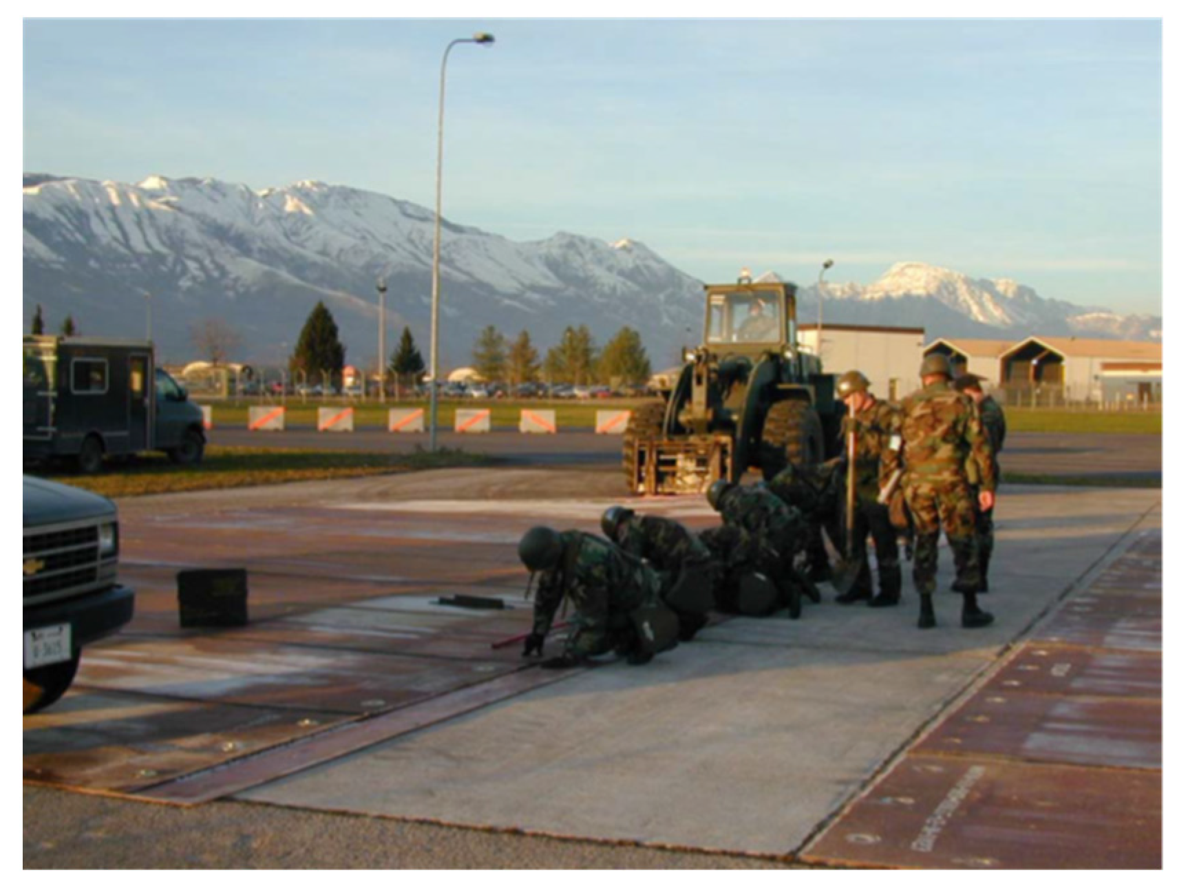
- fiberglass mats: the pavement discontinuity is filled with controlled granulometry stones, rolled and levelled with the unpaired part of the pavement (Figure 1). A fiberglass mat, composed of two or more layers of fiberglass impregnated with polyurethane or polyester resins, is laid upon to prevent FOD risk [12]. Finally, the mat is anchored to the pavement with bolts and plugs. This method is simple and rapid: its longest procedure is fixing to the ground [13].
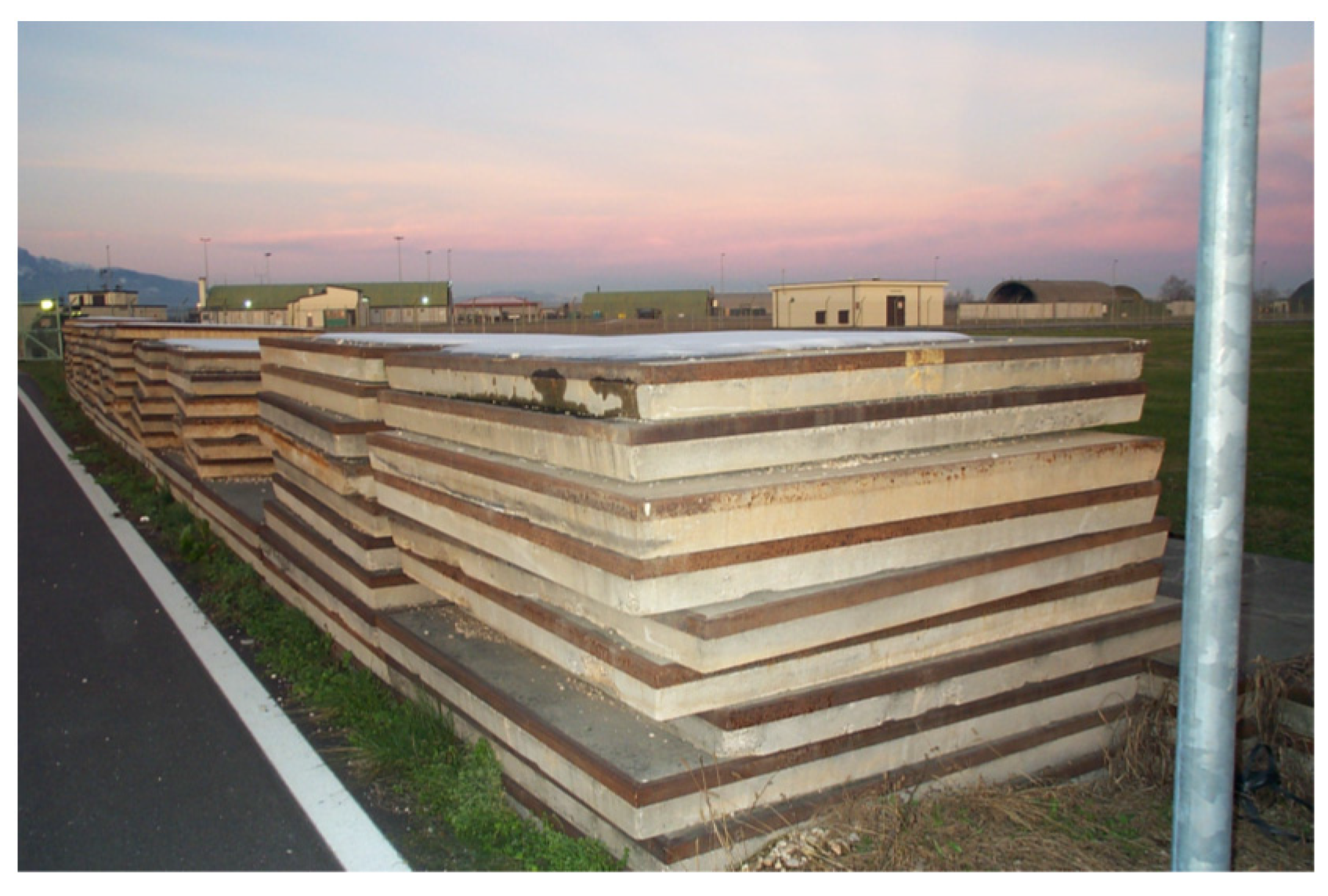
- precast concrete slabs: precast concrete slabs 1.5 × 1.5 m wide and 15 cm thick are laid down on a foundation levelled, which is 15 cm under the final pavement level (Figure 2) [14]. Slabs have a steel containment profile around their perimeter, double internal reinforcement, and two slots for lifting [15]. The system guarantees bearing capacity and durability, but has several operational difficulties: existing pavement should be cut to contain exactly a proper number of slabs; hot mastics, resins or hot bitumen should be applied to finish the joints [16].
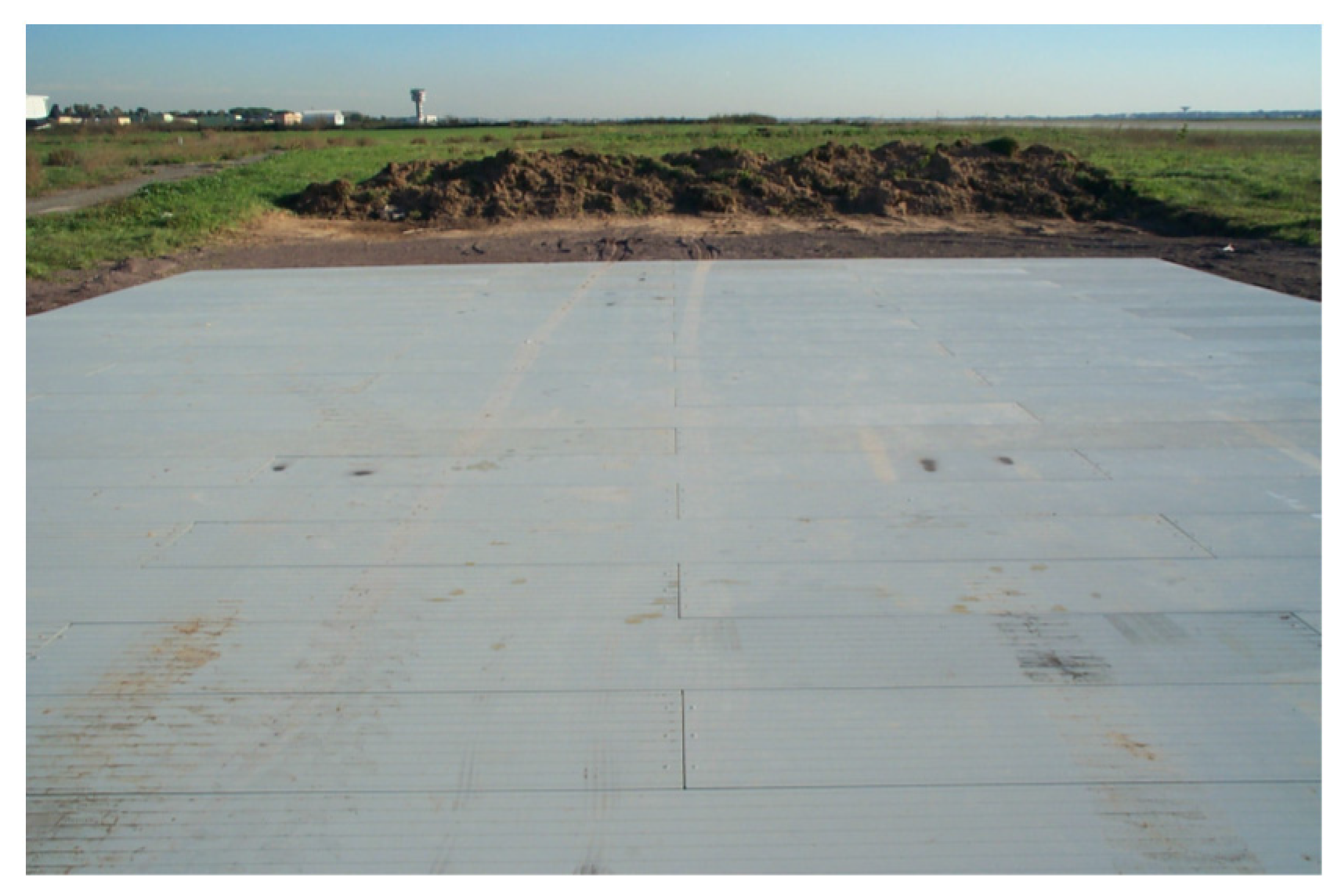
- metal mats: prefabricated metal elements are suitable for both recess and covering execution (Figure 3). Usually, aluminium mats 4 cm thick are used because their high strength and low weight. Joints are simple and exact, outside elements are tied to avoid removal of elements and risk of FOD.
Site repairs restore pavement continuity creating a structural package filling the crater or the discontinuity. Quickly hardening cement/resin-bounded mortars or bituminous emulsions are used. Three types of interventions are possible:
- recovery by percolation: the crater is filled with part of the material (10–70 mm diameter) spilled from the crater itself, then different materials of suitable granulometry complete the filling up to reach the ground level. Percolation of cementitious or bituminous binders finishes the upper thickness of the pavement. The granulometry of filling material varies with the used binder: it is 10–25 mm when it is bitumen, 25–70 mm when it is cement;
- recovery by surface filling: the crater is filled as in the previous case, but no more than 5–8 cm from the final level; a surface layer of cold bituminous asphalt composes the new upper layer and completes the repair;
- recovery by deep filling: the crater is filled as before, up to 20–30 cm from the final level; the restoration will be realized using ordinary concrete.
Site repairs are more frequent than modular repairs because they are more versatile: they allow repair under various conditions (e.g., extension of pavement to be repaired, volume to be filled…). Their technique could be used also in road sector, where site repairs are just about the only used and rapid ones are desirable [17,18,19]. Under such conditions, the study focused on evaluation and identification of the best technical solution for easy and rapid pavement repair. As consequence of this condition, the study examined 12 materials and mixtures having with reference the NATO standard STANAG 2929 [11], which defines the maximum time for airport reopening after a repair work. Laboratory and in situ [20,21] tests have been performed to find the best choice from a technical point of view; finally, the examined materials have been compared respect to their installation costs. The results from this work provide interesting information useful to design a RRR, both for airport and road pavements.
2. Materials and Methods
Four different categories of materials used for repairing airport pavements have been examined in the study: bituminous emulsions, quick-hardening cement mortars, ordinary cement concretes, cold bituminous conglomerates, and an expanding resin (Table 1).
Two bituminous emulsions have been tested:
- E1 is an over-stabilized cationic emulsion composed of 60% styrene-butadiene-styrene (SBS)-modified bitumen. Table 2 lists technical characteristics of bitumen extracted from the emulsion.Its correct temperature use ranges from 5 and 80 °C; moreover, it contains structural regenerative additives, therefore it is suitable for cold state repairs.
- E2 is a bicomponent modified, workable cold bitumen: it is useful for pavement maintenance when temperature ranges between 10 and 30 °C. Its maturity time is not more than 45 min after mixing the two components.Five quick-hardening cement mortars (see Table 1) have been tested:
- the first and second cement mortars are composed of a Portland cement respectively 32.5 (M1) and 42.5 (M2) compliant with the standard EN 197-1 [22]. Mortars have been mixed with a water/powder (w/p) ratio equal to 0.45;
- the third cement mortar (M3) is a one-component fast setting and hardening cement with silica fume mortar [23,24,25]. It is fibre reinforced, suitable for smoothing, filling, and repairing concrete surfaces. Its correct w/p ratio is 0.13. Its elastic modulus evaluated according to the standard EN 13412 [26] is 32.6 GPa.
- the fourth cement mortar (M4) is a one-component fast setting and hardening cement mortar with graded aggregates. It is suitable for smoothing, filling, and repairing concrete surfaces; for thickness over 5 cm it is suitable for casting with 6/10 aggregates without segregation. Its correct w/p ratio is 0.125. Its elastic modulus evaluated according to the standard EN 13412 [26] is 32.6 GPa.
- the fifth cement mortar (M5) is a thixotropic, non-shrink, fibre reinforced, fast setting and hardening hydraulic mortar with graded aggregates. It is suitable for filling and repairing concrete surfaces. Its correct w/p ratio is 0.22. Its elastic modulus evaluated according to the standard EN 13412 [26] is 22 GPa.
Figure 4 compares the granulometry curves of M3 and M5.
The cement mortars M3 and M5 have similar granulometric curve: both have over 33% percentage passing at 63 μm, and over 98% percentage passing at 4 mm. Nevertheless, M5 has more fine content than M3, while it has less fine sand than M3: these differences explain the different w/p ratios above listed.
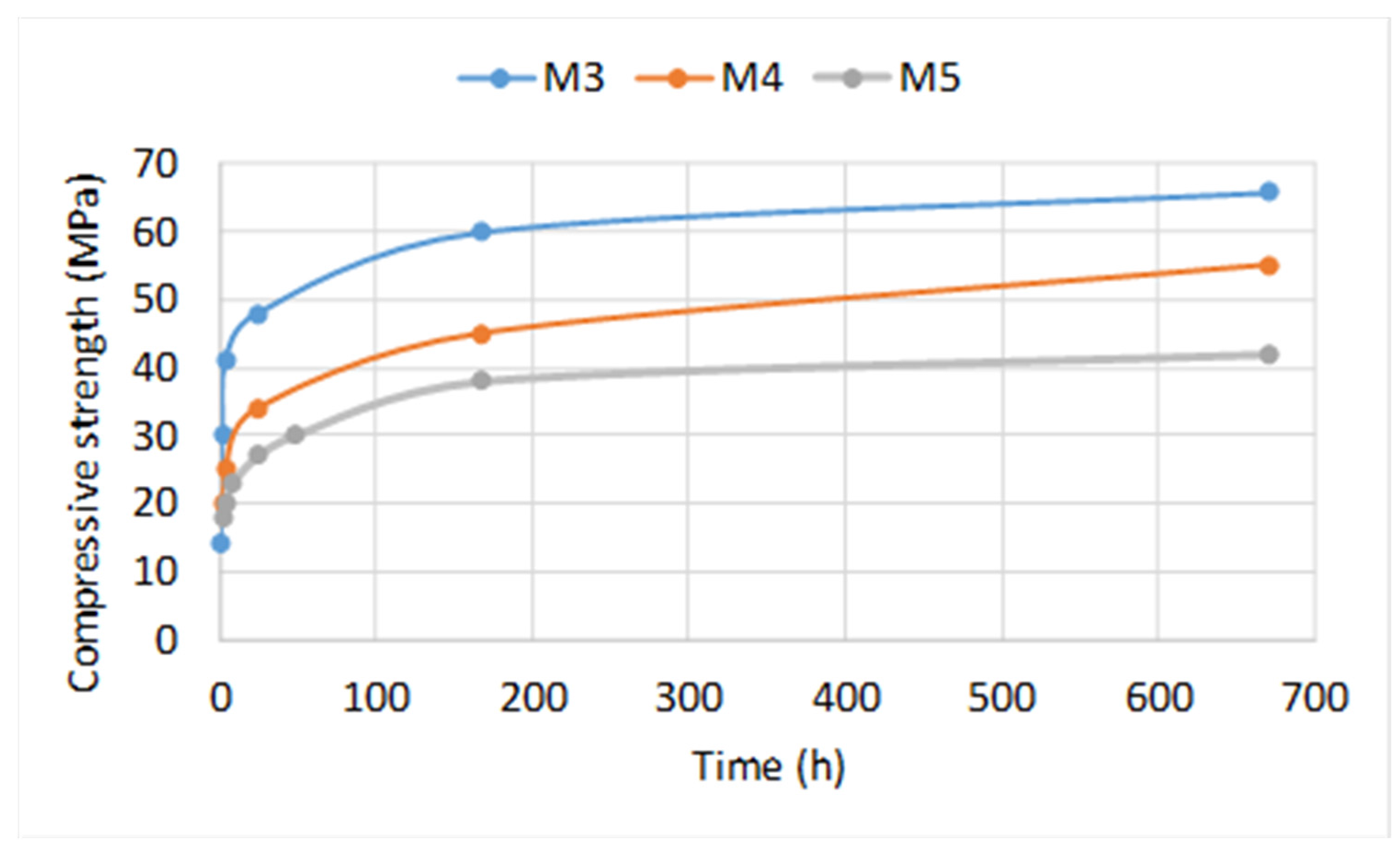
Figure 5 compares the compressive strength of cement mortars M3, M4 and M5 whose time, temperature, and procedures for laying are compliant with those adopted for ordinary cement concrete. Compressive strength has been evaluated after maturity at 20 °C according to the standards: EN 12190 [27] for M3 and M4, and UNI EN 1015-11 for M5 [28].
Figure 6 compares the flexural strength of cement mortars M3, M4 and M5. Flexural strength has been evaluated after maturity at 20 °C according to the standards: EN 196-1 [29] and EN 13813 [30] for M3 and M4, and EN 1015-11 [28] for M5.
Four cold bituminous mixtures (see Table 1) have been considered. Time, temperature, and procedures for their laying are compliant with those adopted for ordinary asphalt.
- B1 is a premixed cold bituminous mixture composed of fine aggregates and bitumen (6% by volume). After its application, the pavement can be immediately re-opened to traffic. The traffic itself settles the material, ensuring adhesion to the existing paving. This feature reduces time and costs for compaction, which cannot be overlooked using ordinary asphalt mixes [31]. Table 3 lists mechanical characteristics of B1 evaluated according to the standard ASTM D6927 (75 blows on each side) [32].
- B2 is a one-component premixed asphalt: it permits to repair 20–70 mm thick potholes with a single layer application. Table 4 lists technical characteristics of B2.
- B3 is a bicomponent premixed cold asphalt: it permits to repair bituminous and concrete pavements with up to 7 cm thick layers. Water is its catalyst for the hardening process.
- B4 is a premixed cold asphalt composed of bitumen (5.5% by weight of aggregates), vegetal oils, plasticizer additives and aggregates. It permits to repair bituminous and concrete pavements with layers not less than 2 cm and up to 6 cm thick.
Table 5 lists technical characteristics of B4.
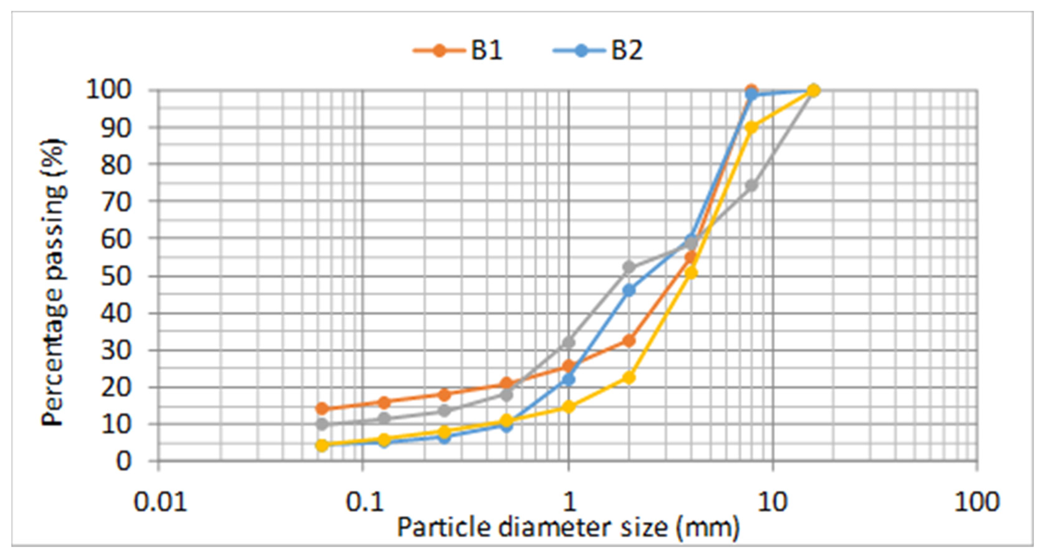
Figure 7 compares the granulometry curves of B1, B2, B3, and B4.
Expanding resins are used for transport infrastructures when the bearing capacity of soil does not satisfy the design requirements. Their expansion allows consolidation treatment by mean removal of the interstitial water and/or the filling of voids. The consolidation treatment involves executing injections through small metal cannulas placed on a regular mesh on the area to be treated.
In the study, a high-density bi-component polyurethane resin R (see Table 1) has been tested: its starting time is 40 ± 2 s and its expansion time is 85 ± 10 s. Table 6 lists its technical characteristics.
In the first phase of the study, the presented 12 materials were tested in the Laboratory of the Italian Air Force (2nd Department of Genio located in Ciampino-Rome) to verify:
- ease of mixing and laying;
- percolability through a D40-70 grain size class (for emulsions and mortars);
- self-levelling properties;
- Marshall stability of cold conglomerates;
- cubic compressive resistance of cement mortars and expanding resin.
According to the need for fast reopening of the airport, mechanical resistance tests were conducted with the timing of 3 h, 6 h, 12 h, 24 h, and 48 h, 3days, 7days, and 28 days to evaluate the maturity of the products.
The texts performed were:
2.1. Percolation Tests with Bituminous Emulsions and Cement Mortars
The percolation test is a laboratory test designed by the 2nd Department of Genio of the Italian Air Force to verify the performance of a granular material bounded by a percolated binder. The procedure involved 7–12 mm granular materials with bituminous emulsions and 40–70 mm aggregates with cementitious mortars. In all cases, the tests aimed to find the binder composition (i.e., content of water for E1, content of cement for E2 and the mortars) which allows a percolation of about 20 cm and therefore it is defined “optimum”; otherwise the binder consistency is “fluid” (if the percolation thickness is more than 20 cm) or “plastic” (if the percolation thickness is lower than 20 cm).
2.2. Structural Strength of Concrete Obtained from Cement Mortars and Standard 32.5/42.5 Cement Concrete
Concrete made from cement mortars was obtained by percolating mortar inside 15 cm cubic moulds where the aggregates were previously located. Specimens were tested according to the standard EN 12390-2 [33].
In this phase specimens with ordinary concrete mixed with cement 32.5 and 42.5 and water/cement ratio equal to 0.500 were also tested. During the mixing process, the authors observed a rather aggressive gripping phenomenon in cement concrete 42.5, which could lead to difficulties during works.
2.3. Marshall Stability of Cold Bituminous Mixtures
Different series of Marshall specimens [34] have been made to evaluate the increments of resistance to time: for each time and cold bituminous mixture, 4 specimens have been tested.
2.4. On-Site Tests
On-site repairs were designed using the software FAARFIELD 1.41 (Federal Aviation Administration Rigid and Flexible Iterative Elastic Layered Design) (Federal Aviation Administration, Washington, DC, USA) [35]. It provides possible configurations of flexible and rigid pavement layers by simulating the number of coverages of the traffic mix. In this study, the layers thickness was calculated considering a reference aircraft, the C-130J (Lockheed Martin, Bethesda, MD, USA), typical for civil and military operations of the Italian Air Force. For this aircraft, the load distribution at the time of landing is 5% on the front gear and 95% on the rear one. 500 annual coverages during 20-year service life were considered: this volume traffic permit to design a permanent repair, as defined by the NATO criteria [36]. The flexible pavement model was used for bituminous materials, while the rigid pavement model was used for cementitious materials and the expanding resin [37,38].
The on-site tests involved the best performing materials found during the laboratory experimentation.
3. Results
3.1. Percolation Tests with Bituminous Emulsions and Cement Mortars
The results of percolation tests are listed in Table 7.
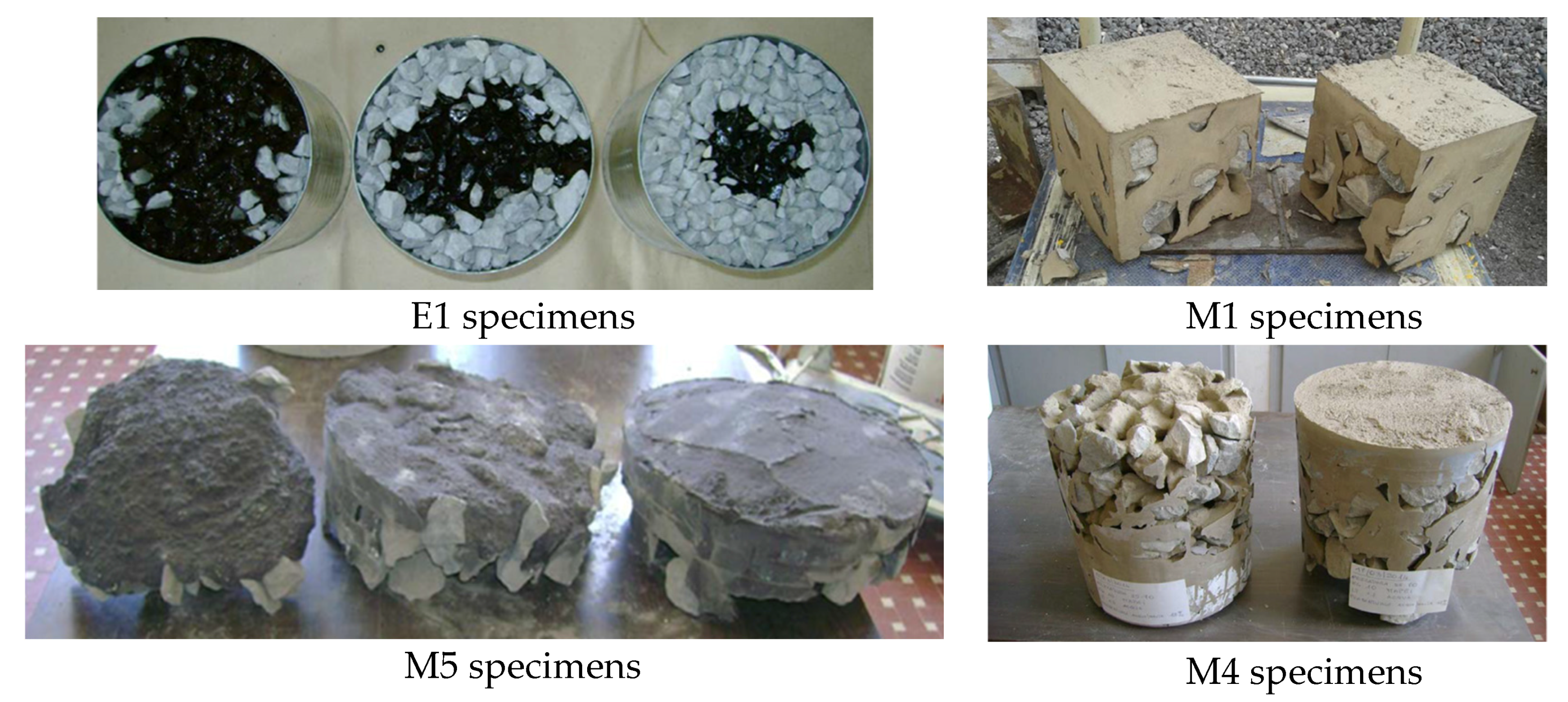
Figure 8 shows some percolation specimens obtained during the study.
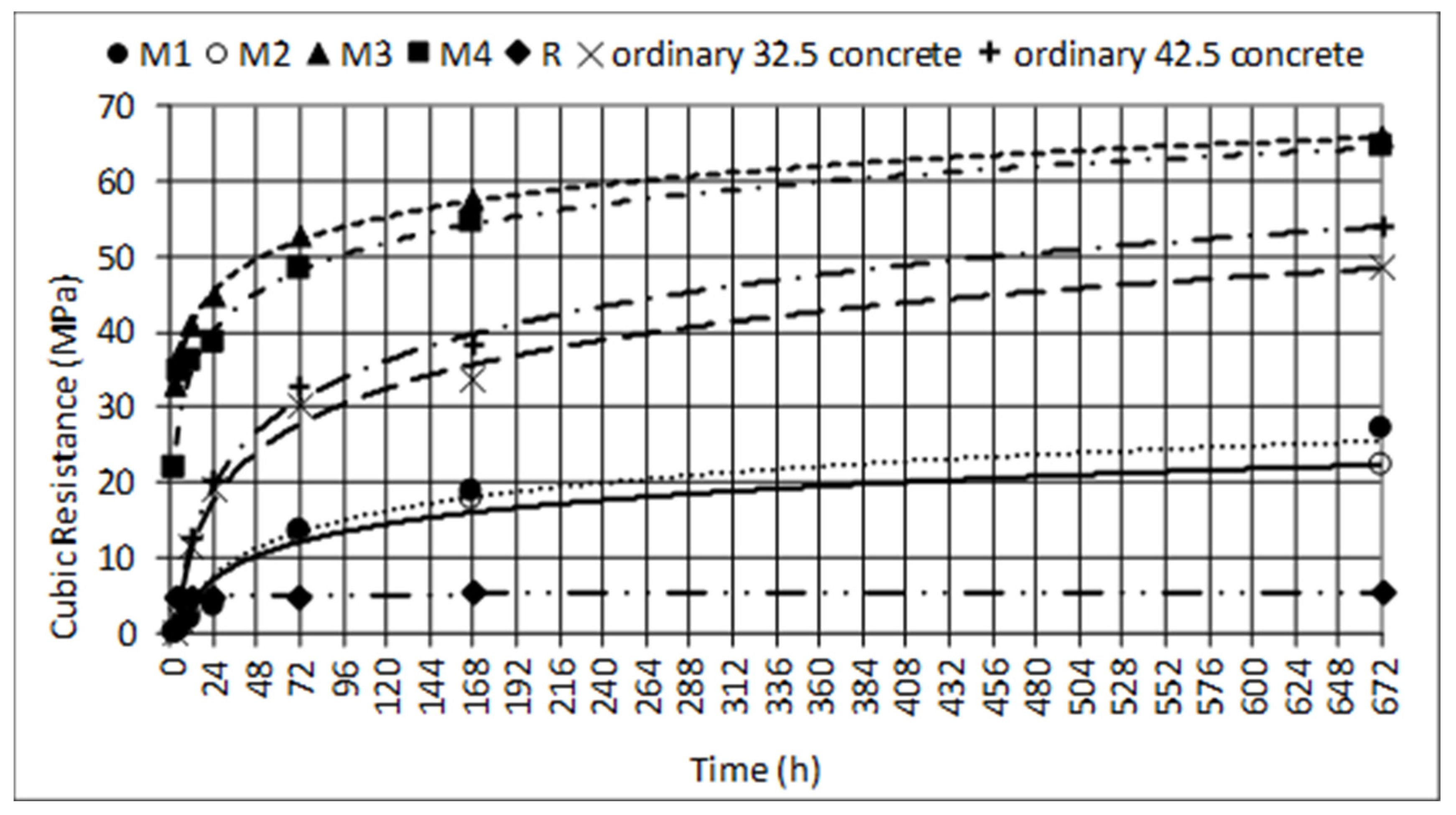
3.2. Structural Strength of Concrete Obtained from Cement Mortars and Standard 32.5/42.5 Cement Concrete
The results of compression tests on cementitious mixes are listed in Table 8.
Figure 9 highlights M3 and M4 have mechanical features that can be used as solutions for RRR, especially when percolation needs. M1 and M2 exhibited a high percentage of voids and, consequently, lower mechanical characteristics than the ordinary concretes mixed with 32.5 and 42.5 cements (both CEM I type). Ordinary concretes have mechanical characteristics that can be used as solutions for RRR, especially for deep filling.
3.3. Marshall Stability of Cold Bituminous Mixtures
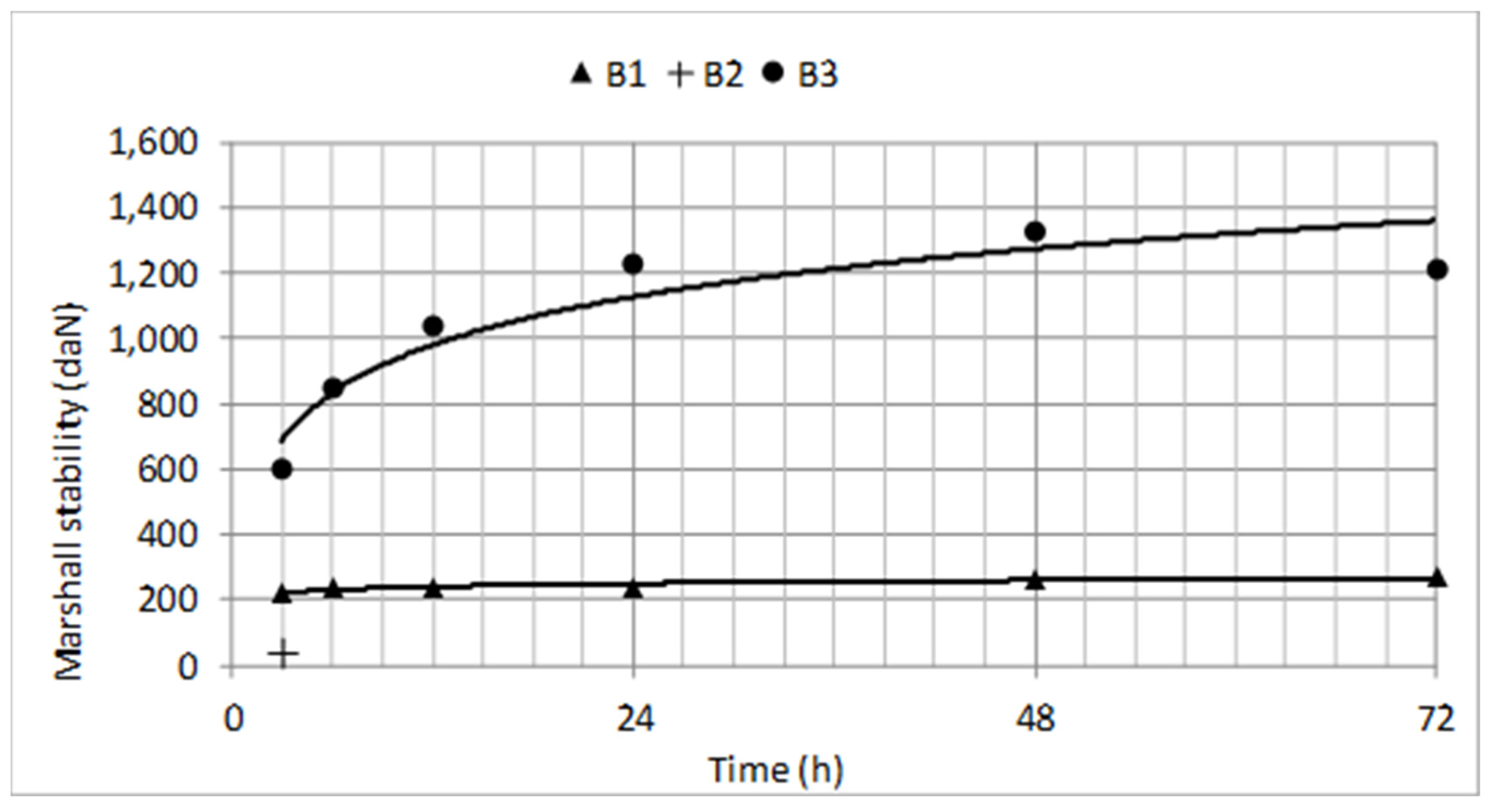
Table 9 shows the Marshall stability of the examined cold bituminous mixtures at different times.
Figure 10 shows that B1 had insufficient mechanical characteristics to allow the rapid repair of the runways; B2 had only one specimen able to be tested; B4 did not have consistency: its specimen broke even before being inserted into the press. Only B3 showed mechanical characteristics appropriate for rapid repair.
At the end of this laboratory experimentation, the more reliable products which could be used for the runway rapid repair were: M4, B3, and M1. These materials and the expanding resin were used for on-site tests.
3.4. On-Site Tests
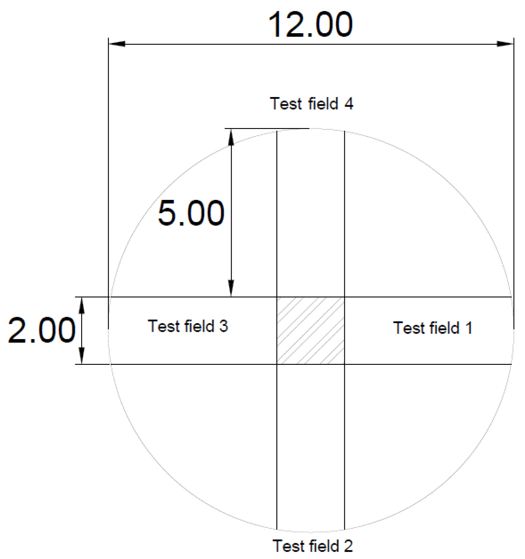
The on-site experimentation involved four test fields to be repaired, arranged in a 12-m diameter circle (Figure 11).
The test fields were sized to avoid the disturbance effects due to the loads from the adjacent test fields. Their characteristics were:
- Test field 1: consisting of a D40-70 stone foundation and B3 wearing (flexible pavement);
- Test field 2: consisting of a D40-70 stone foundation and M1 wearing (rigid pavement);
- Test field 3: consisting of a D40-70 stone foundation up to 20 cm from the ground level, overlaid by a geotextile and a further layer of crushed stone with M4 used by percolation, (rigid pavement);
- Test field 4: consisting of an expanding resin injected into a stone foundation (40–70 mm) to increase its bearing characteristics and to create a support for concrete slabs.
During the execution of the expanding resin injection into the layer of stone, there was a strong expansion of the mixture, even up to 20 cm (Figure 12).
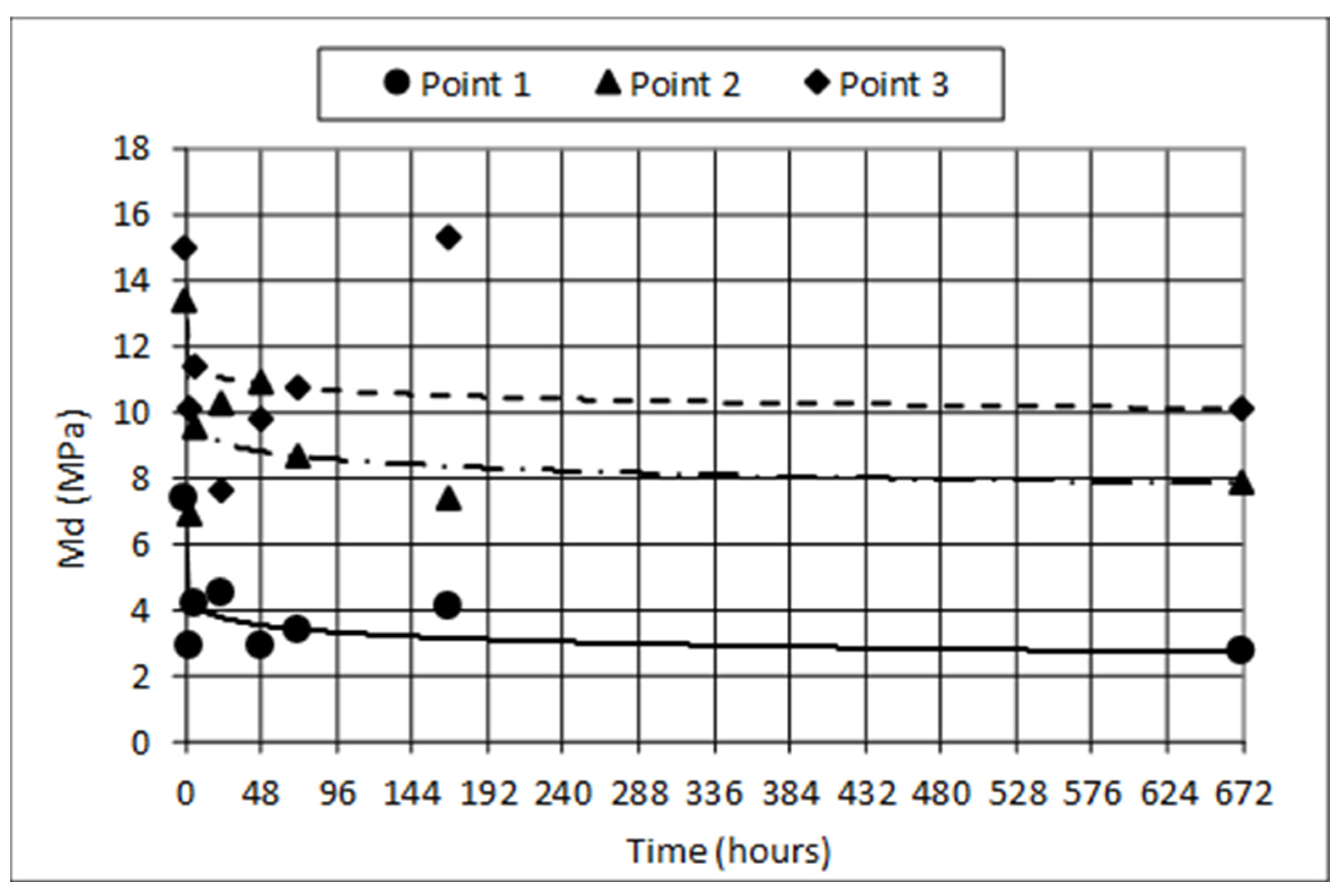
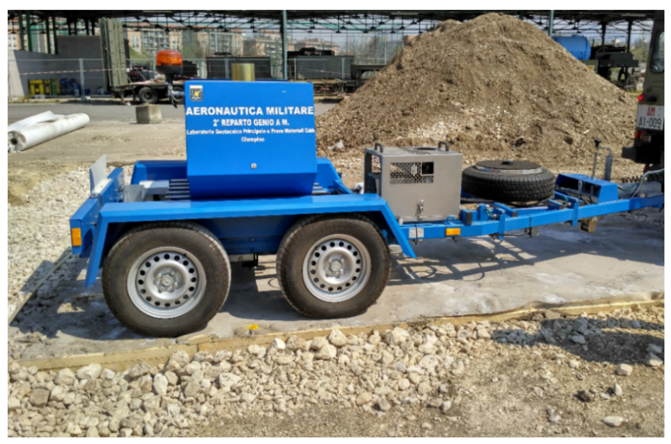
The on-site experimentation allowed the verification of the load bearing during time through Light Weight Deflectometer (LWD) and Heavy Weight Deflectometer (HWD) tests. LWD was used to evaluate the pavement Deformation Modulus Md under the resin-treated area [39]. HWD technology allowed to back calculate the elastic modules of the repair layers by mean the software Elmod® 6.1.75 (Dynatest: Søborg, Denmark) [40]. According to the measured site deflection data, the software gave back an approximated deflection basin with decay curves according to the material under study.
The results listed in Table 10 highlight high variable values of Md, as confirmed by the statistical results listed in Table 11. The set of values for conducting this analysis corresponds to the Md values of the different tested points at different times. For every testing time, the mean, standard deviation, and coefficient of variation (CV, defined as the ratio of the standard deviation to the mean) were calculated.
The high values of CV reveal that this technology is not reliable, as confirmed by the decreasing trend of Md in Figure 14.
The observed decreasing of Md is caused by the viscous properties of the resin and its pronounced expansion which mobilizes the granular material. Indeed, this process alters the lithic skeleton because the resin replaces the stones instead of occupying the gaps between them. The mechanical performances shown in Table 10 and Figure 14 prevent the use of the expanding resin as material useful for RRR.
As done for LWD tests, the results of HWD tests and back calculation were performed for different times. During the analysis of the data some inconsistencies were found in the evaluation of the elastic moduli. For a more accurate evaluation of the moduli, filtering of data measured by the tenth geophone, which was always on the extreme edge of the test fields, was carried out (Figure 15).
The filtering process gave more precise and realistic results in terms of elastic modulus E of the pavement layers. In the first measurements (3 h), only the contribution of five geophones was filtered, according to the Dynatest guidelines [41].
A layered elastic model has been modelled to compute stresses, strains and deflections caused by surface load at any point in the pavement structure. According to the layered elastic theory [42], the model assumed that each pavement structural layer was homogeneous, isotropic, and linearly elastic. Table 12 lists the geometrical properties of the pavements modelled with the software Elmod® 6.1.75 [41].
Top layers are composed of tested binders percolated into D40-70 granular bottom layers. The subgrade is the natural material underneath the test fields.
Table 13, Table 14 and Table 15 list the elastic moduli obtained from back analysis respectively for test field with B3, M1 and M4 materials.
In the test fields 1 and 2, the values of the bottom layers elastic modulus (E2,B3 and E2,M1) were the same, equal to 450 MPa. This value of E2 has been calculated before laying the top materials B3 and M1, and it has been assumed as constant during the subsequent analysis. This choice avoided anomalous back calculation results due to the small tests areas (10 m2 each). Indeed, under ordinary conditions, the HWD tests are performed on areas larger than those prepared in this study, therefore the wave transmission in the study differs from usual. The most important differences involve the lower layers, whose elastic moduli are deduced from the responses of the geophones most distant from the loading plate. In this case, the response of the most distant geophones is also the most affected by side effects. On the other hand, this assumption has not been possible due to the technical characteristics of the third test field. M4 is a percolated material, thus the thicknesses and mechanical properties of layers are not defined and constant as those of test fields with materials B3 and M1.
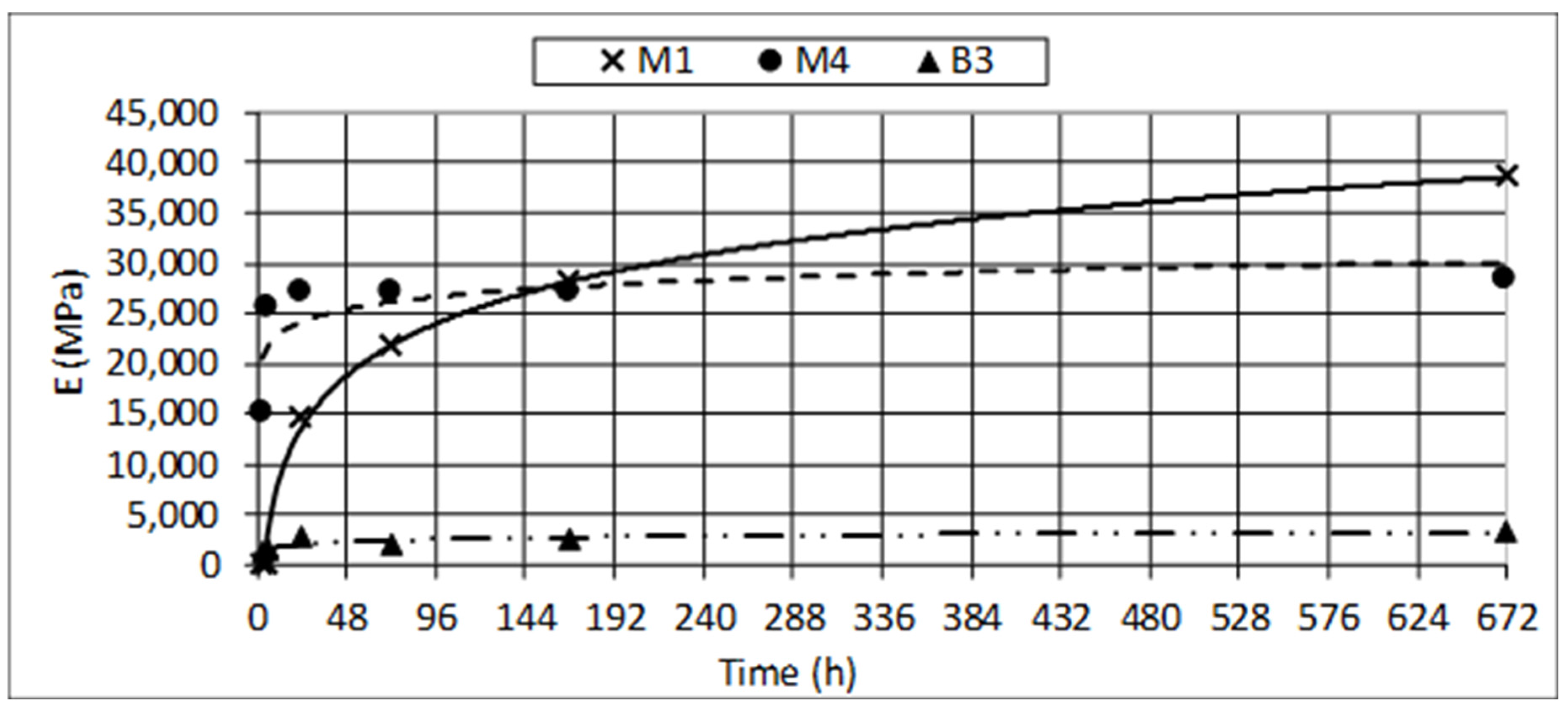
Figure 16 shows the evolution of the elastic modulus of top layers paved with M1, M4 and B3.
Figure 16 highlights the mechanical performance of B3 are not comparable with those obtained using the ordinary cement concrete (M1) and the cementitious mortar M4. M4 has the most rapid rate of increase of elastic modulus: its E value is about constant after 1 day. On the contrary, for M1 the increase of the elastic modulus is slower, but its elastic modulus is comparable to that of M4 at 7 days and is growing until at least 28 days, when the difference is appreciable (38.6 GPa for M1 versus 28.4 GPa for M4).
4. Discussion
At the end of HWD tests, the ACN/PCN method was used to evaluate the load bearing capacity of the tested materials [43,44]. It is a system of rating airport pavements designated by the International Civil Aviation Organization [45] to compare the airport pavement strength (Pavement Classification Number, PCN) to the operation conditions of the traffic mix considering its gross weight and the subgrade bearing capacity (Aircraft Classification Number, ACN). The ACN value is twice the derived single-wheel load expressed in thousands of kilograms, with single-wheel tire pressure standardized at 1.25 MPa, which requires the same pavement thickness required by the examined aircraft. The calculation methods of ACN consider for flexible pavements 10,000 coverages and for rigid pavements 2.75 MPa concrete working stress [44]. Both values are representative of typical airport pavements.
Two criteria allow the evaluation of PCN: the “Using” aircraft or the “Technical” evaluation methods [44]. The first one is based on the experience, the second one on analytical procedures. In this study, the technical method proposed by the software Elmod® 6.1.75 has been used to calculate the PCN value. It considers the elastic modulus of layers (evaluated by mean back calculation), the configuration of the main gear of the design aircraft, and the number of coverages during the service life.
An airport pavement is verified when Equation (1) is satisfied:
PCN ≥ ACN.
Data obtained in the HWD tests allowed the calculation of the PCN, using the software Dynatest Elmod® 6.1.75 [40]: different values were calculated for B3, M1, and M4 test fields at different maturity ages and for three traffic levels. 100, 1000 and 10,000 coverages during the service life were considered to simulate expedient, temporary, and permanent repairs according to the standard STANAG 7208 [36].
In the study, the subgrade under the test fields (Figure 11) was classified as “C” (low strength), therefore the ACN of the reference aircraft is 35.
Table 16, Table 17 and Table 18 list PCN values obtained for test field respectively with B3, M1 and M4 materials: the red cells indicate PCN<ACN, while green ones PCN ≥ ACN.
The results reveal M4 has the most rapid PCN evolution: after 6 h maturity time, the verification ACN/PCN is satisfied. B3 and M1 ensure comparable results, but their reopening time (when Equation (1) is satisfied) is longer (7.5 days) than that of M4.
At the end of the study, an economic analysis has been carried out to estimate the unit costs for repairing a runway discontinuity [46,47]. Unit costs derive from the official price list used by the Italian Air Force (internal document) (Rome, Italy). Table 19 lists the results of the economic analysis.
According to the results listed in Table 19, M4 is the material that best suits needs for RRR: its technical and economic characteristics balance the conflicting objectives of budget and performance. Using M4, the airport could be reopened 3 h after the conclusion of the emergency repair (100 coverages during the service life), while 6 h after the RRR works it is possible to achieve a permanent repair, which allow 10,000 coverages during the service life.
5. Conclusions
The need for rapid repairing runway pavements has grown fast over the years, both for civil purposes and for peacekeeping missions. Therefore, there is the need for a technology that could be applied balancing conflicting objectives of resistance and rapidity. At this purpose, on-site repairs are more versatile than modular repairs currently used in the military sector because they can be adapted to different conditions. The specific sector of runway construction currently needs the comparison of technical performances offered by the innovative materials used for on-site repairs. In Italy, the Laboratory of the Italian Air Force (2nd Department of Genio) analysed technical and economic performances of several types of rapid runway repairs having the C-130J aircraft was as design aircraft. 12 materials currently used for pavement repair have been tested to evaluate their laboratory and on-site performances at different times.
This paper presents the first experimental results obtained on the following materials:
- 2 bituminous emulsions,
- 5 cement mortars,
- 4 cold asphalt mixes,
- 1 expanding resin.
The experimental study involved two phases:
- laboratory tests on all materials except resin to focus on:
- ease of mixing and application;
- percolability (for emulsions, mortars and concretes);
- Marshall stability (for cold asphalt mixes).
- on-site experiments on the materials which performed the best for repairing. A cold asphalt mix, a cement mortar, an ordinary cement concrete and the expanding resin were used to repair four 10 m2 widespread areas. All three tested mixes required time, temperature, and procedures compliant with those used to lay ordinary cement and bituminous runway pavements. On the contrary, the expanding resin required dedicated instruments to be injected. The bearing performances have been evaluated using the ACN/PCN system (for the three mixes) or LWD (for the expanding resin).
The on-site results highlighted that:
- it is not possible to repair runway pavement with expanding resin for two reasons: its strong expansion, even up to 20 cm over the desired level, and its bearing performances. Indeed, the LWD tests showed a decreasing value of deformation moduli over maturity time;
- the tested cement mortar M4 (one-component fast setting and hardening cement mortar with graded aggregates) ensures the fastest runway reopening in presence of a permanent repair of the damaged concrete pavement: 6 h after the work, the runway can be opened to traffic for 10,000 coverages of the design aircraft;
- surface filling (up to 6 cm) with the cold bituminous mixture B3 (bicomponent premixed cold asphalt with water as catalyst) and deep filling repair with the concrete M1 (ordinary concrete mixed with CEM I 32.5) have similar performances: both allow the reopening to traffic after 18 h maturity time, but for only 1000 coverages of the C-130J aircraft. Indeed, M1 and B3 require 7.5 days-age to support 10,000 coverages. B3 and M1 are both suitable for repairing flexible and rigid pavements.
Finally, it was also observed that the unit costs of the examined materials widely vary: B3 has a higher economic impact than that of M1 and M4, mainly due to the material since the costs of machines and works to have the rehabilitated pavement are comparable.
The results also provide a framework and a reference for any further study into specific cases using additional materials. All test methodologies can be applied to simulate with the software FAARFIELD (Version 1.41, Federal Aviation Administration, Washington, DC, USA) a fleet of almost any civil aircraft, therefore the procedure could be replicated for further analysis. As observed in this study, the contribution of each considered material to the overall repair work can be specialized to maximize the performances:
- percolated resin can be used in bottom layers as foundation and base,
- cold bituminous mixtures and cement mortars can be used for top layers.
Author Contributions
Alberto De Rubeis, Mauro Cassata, Paola Di Mascio and Laura Moretti conceived and designed the experiments; Federico Leonelli, Antonello Germinario and Francesco Picarellaperformed the experiments; all the authors analyzed the data and wrote the paper.
Conflicts of Interest
The authors declare no conflict of interest.
References
- Organisation for Economic Co-Operation and Development. Infrastructure to 2030. Volume 2 Mapping Policy for Electricity, Water and Transport; Organisation for Economic Co-Operation and Development: Paris, France, 2007. [Google Scholar]
- Cirianni, F.; Fonte, F.; Leonardi, G.; Scopelliti, F. Analysis of lifelines transportation vulnerability. Procedia Soc. Behav. Sci. 2012, 53, 29–38. [Google Scholar] [CrossRef]
- Tong, S.Q.; Wang, N.; Song, N.Q. Emergency evacuation capability evaluation and optimization for an offshore airport: The case of Dalian Offshore Airport, Dalian, China. Saf. Sci. 2017, 92, 128–137. [Google Scholar] [CrossRef]
- Shibayama, T. Japan’s transport planning at national level, natural disasters, and their interplays. Eur. Transp. Res. Rev. 2017, 9, 44. [Google Scholar] [CrossRef]
- Ripley, T. Runway Repair Delays threaten Dutch F-16 deployment; Jane’s Defence Weekly: London, UK, 2006; pp. 353–354. [Google Scholar]
- Loprencipe, G.; Zoccali, P. Comparison of methods for evaluating airport pavement roughness. Int. J. Pavement Eng. 2017, 1–10. [Google Scholar] [CrossRef]
- Loprencipe, G.; Cantisani, G. Evaluation methods for improving surface geometry of concrete floors: A case study. Case Stud. Struct. Eng. 2015, 14–25. [Google Scholar] [CrossRef]
- Bonin, G.; Cantisani, G.; Loprencipe, G.; Ranzo, A. Dynamic effects in concrete airport pavement joints. Ind. Ital. Cem. 2007, 77, 590–607. [Google Scholar]
- Miccoli, S.; Finucci, F.; Murro, R. Assessing project quality: A multidimensional approach. Adv. Mater. Res. 2014, 1030–1032, 2519–2522. [Google Scholar] [CrossRef]
- Miccoli, S.; Finucci, F.; Murro, R. Criteria and procedures for regional environmental regeneration: A European strategic project. Appl. Mech. Mater. 2014, 675–677, 401–405. [Google Scholar] [CrossRef]
- NATO. STANAG 2929, AATMP-03 (Allied Air Traffic Management Publication) “Airfield Damage Repair (ADR) Capability”; North Atlantic Treaty Organization: Brussels, Belgium, 2016. [Google Scholar]
- Dukes, P.E. Rapid runway repair: Fiberglass mats pass the test. Mil. Eng. 1988, 80, 453–455. [Google Scholar]
- Dover, D.; Anderson, M.; Brown, R.W. Recent Advances in Matting Technology for Military Runways. In Proceedings of the 27th Annual International Air Transport Conference, Orlando, FL, USA, 30 June–3 July 2002. [Google Scholar]
- Ashtiani, R.S.; Jackson, C.J.; Saeed, A.; Hammons, M.I. Pre-Cast Concrete Panels for Rapid Repair of Airfield Rigid Pavements; Air Force Research Laboratory Materials and Manufacturing Directorate Airbase Technologies Division: Washington, DC, USA, 2012. [Google Scholar]
- Bull, J.W.; Woodfors, C.H. Design of precast concrete pavement units for rapid maintenance of runways. Comput. Struct. 1997, 64, 857–864. [Google Scholar] [CrossRef]
- Sander, T.C.; Roesler, J.R. Case study: Runway 12L-30R keel suction rehabilitation, Lambert—St. Louis International Airport. In Proceedings of the 2006 Airfield and Highway Pavement Specialty Conference, Atlanta, GA, USA, 30 April–3 May 2006; pp. 872–884. [Google Scholar]
- Wang, Y.; Kong, L.; Chen, Q.; Lau, B.; Wang, Y. Research and application of a black rapid repair concrete for municipal pavement rehabilitation around manholes. Constr. Build. Mater. 2017, 150, 204–213. [Google Scholar] [CrossRef]
- Guan, Y.; Gao, Y.; Sun, R.; Won, M.C.; Ge, Z. Experimental study and field application of calcium sulfoaluminate cement for rapid repair of concrete pavements. Front. Struct. Civ. Eng. 2017, 11, 338. [Google Scholar] [CrossRef]
- Shanahan, N.; Bien-Aime, A.; Buidens, D.; Meagher, T.; Sedaghat, A.; Riding, K.; Zayed, A. Combined effect of water reducer-retarder and variable chloride-based accelerator dosage on rapid repair concrete mixtures for jointed plain concrete pavement. J. Mater. Civ. Eng. 2016, 28, 04016036. [Google Scholar] [CrossRef]
- Kavussi, A.; Abbasghorbani, M.; Moghadas Nejad, F.; Bamdad Ziksari, A. A new method to determine maintenance and repair activities at network-level pavement management using falling weight deflectometer. J. Civ. Eng. Manag. 2017, 23, 338–346. [Google Scholar] [CrossRef]
- Chou, C.P.; Wang, S.Y.; Tsai, C.Y. Methodology of applying heavy weight deflectometer for calculation of runway pavement classification number. Transp. Res. Rec. 1990, 57–64. [Google Scholar] [CrossRef]
- EN (European Committee for Standardization). EN 197-1: 2000. Cement Part 1: Composition, Specifications and Conformity Criteria for Common Cements; European Committee for Standardization: Brussels, Belgium, 2000. [Google Scholar]
- Sadowski, Ł.; Stefaniuk, D. Microstructural evolution within the interphase between hardening overlay and existing concrete substrates. Appl. Sci. 2017, 7, 123. [Google Scholar] [CrossRef]
- Williams, M.; Ortega, J.M.; Sánchez, I.; Cabeza, M.; Climent, M.A. Non-destructive study of the microstructural effects of sodium and magnesium sulphate attack on mortars containing silica fume using impedance spectroscopy. Appl. Sci. 2017, 7, 648. [Google Scholar] [CrossRef]
- Ortega, J.M.; Esteban, M.D.; Rodríguez, R.R.; Pastor, J.L.; Ibanco, F.J.; Sánchez, I.; Climent, M.A. Influence of silica fume addition in the long-term performance of sustainable cement grouts for micropiles exposed to a sulphate aggressive medium. Materials 2017, 10, 890. [Google Scholar] [CrossRef] [PubMed]
- EN (European Committee for Standardization). EN 13412:2006. Products and Systems for the Protection and Repair of Concrete Structures. Test Methods. Determination of Modulus of Elasticity in Compression; European Committee for Standardization: Brussels, Belgium, 2006. [Google Scholar]
- EN (European Committee for Standardization). EN 12190:1998. Products and Systems for the Protection and Repair of Concrete Structures. Test methods. Determination of Compressive Strength of Repair Mortar; European Committee for Standardization: Brussels, Belgium, 1998. [Google Scholar]
- EN (European Committee for Standardization). EN 1015-11:2007. Methods of Test for Mortar for Masonry. Determination of Flexural and Compressive Strength of Hardened Mortar; European Committee for Standardization: Brussels, Belgium, 2007. [Google Scholar]
- EN (European Committee for Standardization). EN 196-1:2016. Methods of Testing Cement—Part 1: Determination of Strength; European Committee for Standardization: Brussels, Belgium, 2016. [Google Scholar]
- EN (European Committee for Standardization). EN 13813:2002. Screed Material and Floor Screeds—Screed Materials—Properties and Requirements; European Committee for Standardization: Brussels, Belgium, 2002. [Google Scholar]
- Cantisani, G.; D’Andrea, A.; Di Mascio, P.; Loprencipe, G. RILEM Book series. In 8th RILEM International Symposium on Testing and Characterization of Sustainable and Innovative Bituminous Materials; Canestrari, F., Partl, M., Eds.; Springer: Dordrecht, The Netherlands, 2016; Volume 11. [Google Scholar] [CrossRef]
- ASTM (American Society for Testing and Materials International). ASTM D6927. Standard Test Method for Marshall Stability and Flow of Asphalt Mixtures; ASTM International: West Conshohocken, PA, USA, 2015. [Google Scholar]
- EN (European Committee for Standardization). EN 12390-2:2009. Testing Hardened Concrete. Part 2: Making and Curing Specimens for Strength Tests; European Committee for Standardization: Brussels, Belgium, 2009. [Google Scholar]
- ASTM (American Society for Testing and Materials International). ASTM D6926. Standard Practice for Preparation of Asphalt Mixture Specimens Using Marshall Apparatus; ASTM International: West Conshohocken, PA, USA, 2016. [Google Scholar]
- Federal Aviation Administration. AC 150/5320-6F—Airport Pavement Design and Evaluation; Federal Aviation Administration: Washington, DC, USA, 2016.
- NATO. STANAG 7208 Airfield Pavement Design Criteria—Study Draft; North Atlantic Treaty Organization: Brussels, Belgium, 2016. [Google Scholar]
- Tiago Bonucci, P. Airfield rigid pavement structural design—A review of main aspects and methods of analysis. In AIP Conference Proceedings, Proceedings of the 2nd International Symposium on Computational Mechanics, ISCM II, and the 12th International Conference on the Enhancement and Promotion of Computational Methods in Engineering and Science, EPMESC XII, Hong Kong–Macau, China; 30 November–3 December 2009; American Institute of Physics: College Park, MD, USA, 2010; Volume 1233, pp. 1339–1344. [Google Scholar]
- Chordá Ayela, A. Flexible pavements in the Barcelona airport enlargement (Pavimentos flexibles en la ampliación del aeropuerto de Barcelona). Carreteras 2010, 4, 29–42. [Google Scholar]
- Di Mascio, P.; Loprencipe, G.; Maggioni, F. Visco-elastic modeling for railway track structure layers [Modellazione del comportamento visco-elastico degli strati della sede ferroviaria]. Ing. Ferrov. 2014, 3, 207–222. [Google Scholar]
- Elmod Software Manual; Dynatest: Søborg, Denmark, 2015.
- Dynatest FWD/HWD Test Systems; Owners Manual; Dynatest: Søborg, Denmark, 2014.
- Boussinesq, J. Application des Potentials a L’Etude de L’Equilibre et du Mouvement des Solides Elastiques; Gauthier-Villars: Paris, France, 1885. [Google Scholar]
- Norman, J.A.; Mumayiz, S.; Wright, P.H. Airport Engineering: Planning, Design and Development of 21st Century Airports, 4th ed.; John Wiley & Sons: Hoboken, NJ, USA, 2011; ISBN 978-0-470-39855-5. [Google Scholar]
- Federal Aviation Administration. AC 150/5335-5C, Standardized Method of Reporting Airport Pavement Strength—PCN; Federal Aviation Administration: Washington, WA, USA, 2014.
- ICAO. Annex 14, Volume I Aerodromes; International Civil Aviation Organization: Montreal, QC, Canada, 2013. [Google Scholar]
- Di Mascio, P.; Moretti, L.; Panunzi, F. Economic Sustainability of Concrete Pavements. Procedia Soc. Behav. Sci. 2012, 53, 125–133. [Google Scholar]
- Moretti, L. Technical and economic sustainability of concrete pavements. Mod. Appl. Sci. 2014, 8, 1–9. [Google Scholar] [CrossRef]
Figure 1.
Anchoring the fiberglass mat.

Figure 2.
Precast concrete slabs with a steel containment profile.

Figure 3.
Metal mats.

Figure 4.
Granulometry curve of M3 and M5.

Figure 5.
Compressive strength evolution of M3, M4 and M5.

Figure 6.
Flexural strength evolution of M3, M4 and M5.

Figure 7.
Granulometry curve of B1, B2, B3, and B4.

Figure 8.
Example of percolation specimens.

Figure 9.
Structural strength depending on time.

Figure 10.
Marshall stability depending on time.

Figure 11.
Diagrams of test fields (unit of measure: m).

Figure 12.
Expansion of expanded resin.

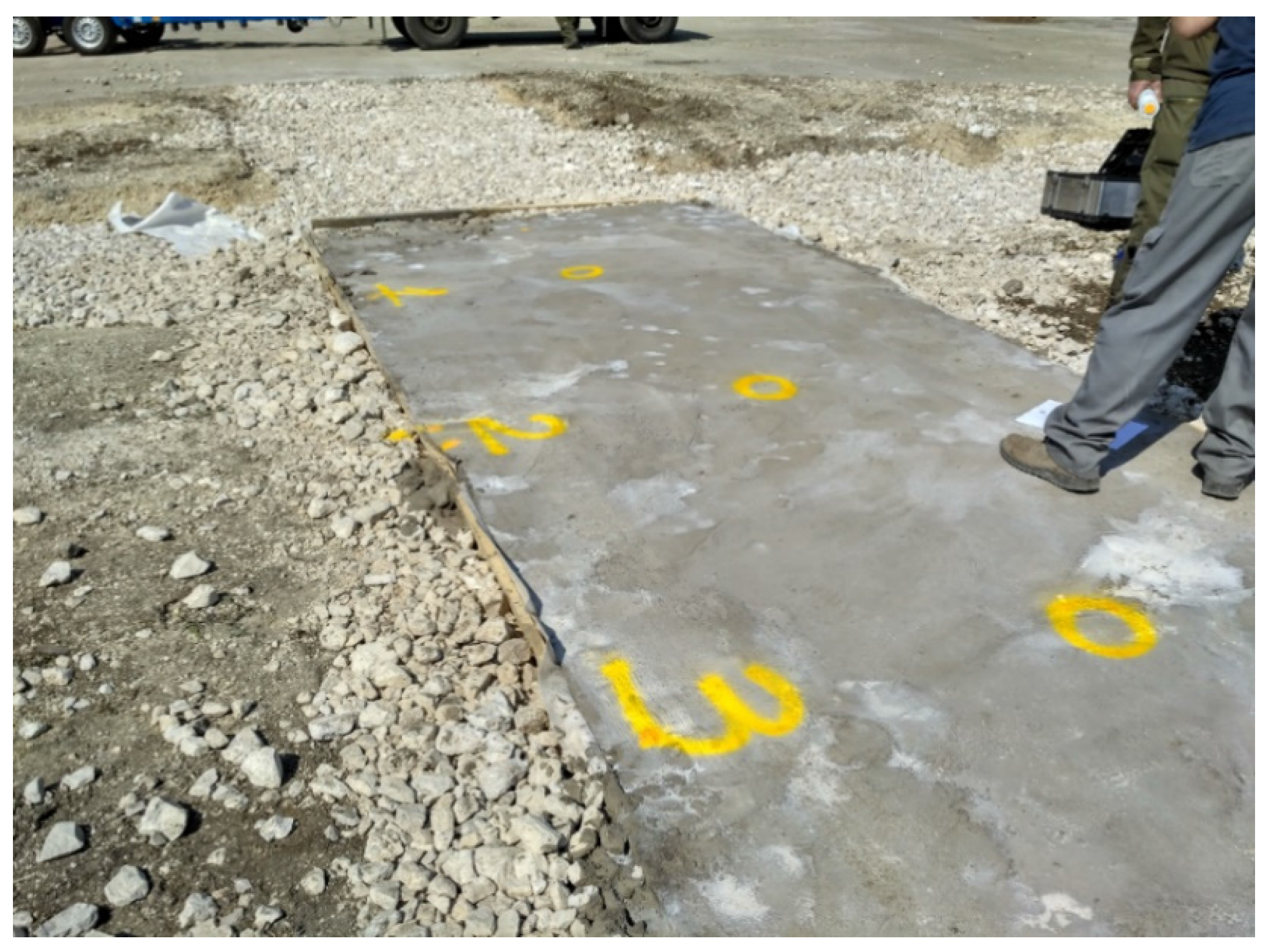
Figure 13.
Resin-treated points of light weight deflectometer (LWD) tests.

Figure 14.
Deformation moduli after the resin injection.

Figure 15.
The HWD machine over the M4-treated area.

Figure 16.
Elastic moduli of top layers.


Table 1.
Materials examined in the study.
| Category | Notation |
|---|---|
| Bituminous emulsions | E1 |
| E2 | |
| Cement mortars | M1 |
| M2 | |
| M3 | |
| Cement concretes | M4 |
| M5 | |
| Cold bituminous mixes | B1 |
| B2 | |
| B3 | |
| B4 | |
| Expanding resin | R |
Table 2.
Technical characteristics of bitumen extracted from the emulsion E1.
| Characteristic | Value | Unit of Measure |
|---|---|---|
| Penetration at 25 °C | 55 | dmm |
| Softening point | 62 | °C |
| Fraas breaking point | −16 | °C |
Table 3.
Mechanical characteristics of bituminous mixture B1.
| Characteristic | Value | Unit of Measure |
|---|---|---|
| Marshall stability at 25 °C after 24 h | >3 | kN |
| Marshall stiffness at 25 °C after 24 h | >1.5 | kN/mm |
| Residual voids | <10 | % |
| Indirect tensile strength of Marshall specimen at 25 °C after 24 h | >55 | kPa |
Table 4.
Technical characteristics of bituminous mixture B2.
| Characteristic | Value | Unit of Measure |
|---|---|---|
| Volumetric mass density | 2.3 | g/cm3 |
| Aggregate size | 0–8 | mm |
| Bitumen content | 7.4–8.4 | % |
| Voids content (after 75 blows Marshall) | 7–9 | % |
| Marshall stability after 24 h under water at 60 °C | ≥4 | kN |
| Marshall flow after 24 h under water at 60 °C | 2–5 | mm |
Table 5.
Technical characteristics of bituminous mixture B4.
| Characteristic | Value | Unit of Measure |
|---|---|---|
| Volumetric mass density | >2.10 | g/cm3 |
| Voids content (after 75 blows Marshall) | <10 | % |
Table 6.
Technical characteristics of the examined expanding resin.
| Characteristic | Value | Unit of Measure |
|---|---|---|
| Compressive strength at 28 days | 5.0 | MPa |
| Shear strength at 28 days | 5.0 | MPa |
| Percentage closed cells | 91.5 ± 1.5 | % |
Table 7.
Results of percolation tests.
| Product | Condition and Results | |||
|---|---|---|---|---|
| E1 | percentage of cement | 0% | 25% | 50% |
| - | fluid | fluid | optimum | |
| E2 | as it is | optimum | - | - |
| M1 | water percentage | 40% | 45% | 50% |
| plastic | optimum | fluid | ||
| M2 | water percentage | 40% | 45% | 50% |
| plastic | optimum | fluid | ||
| M3 | water percentage | 12% | 13% | 14% |
| plastic | optimum | fluid | ||
| M4 | water percentage | 12% | 12.5% | 13% |
| plastic | optimum | fluid | ||
| M5 | water percentage | 16% | 20% | 24% |
| plastic | plastic | plastic | ||
Table 8.
Compressive cubic strength of cementitious mixes.
| Product | Compressive Cubic Strength (MPa) | |||||||
|---|---|---|---|---|---|---|---|---|
| Water/Cement Ratio | Time (h) | |||||||
| 3 | 6 | 12 | 24 | 72 | 168 | 672 | ||
| M1 | 0.450 | 0 | 0.5 | 1.8 | 3.5 | 13.4 | 18.6 | 27.2 |
| M2 | 0.450 | 0 | 0.5 | 2.5 | 4.3 | 13.1 | 17.6 | 22.2 |
| M3 | 0.130 | 32.9 | 37.5 | 41.0 | 44.8 | 52.6 | 57.4 | 65.8 |
| M4 | 0.125 | 21.7 | 34.7 | 36.0 | 38.4 | 48.1 | 54.3 | 64.4 |
| M5 | - | - | - | - | - | - | - | - |
| R | - | 4.59 | 4.60 | 4.72 | 4.74 | 4.77 | 5.45 | 5.42 |
| Concrete with cement 32.5 | 0.500 | 0.13 | 1.8 | 11.5 | 19.2 | 30.2 | 33.5 | 48.5 |
| Concrete with cement 42.5 | 0.500 | 0.31 | 2.3 | 12.6 | 20.4 | 32.9 | 38.4 | 54.0 |
Table 9.
Marshall stability.
| Product | Marshall Stability (daN) | |||||
|---|---|---|---|---|---|---|
| Time (h) | ||||||
| 3 | 6 | 12 | 24 | 48 | 72 | |
| B1 | 222 | 238 | 241 | 240 | 266 | 270 |
| B2 | 36 | - | - | - | - | - |
| B3 | 599 | 850 | 1041 | 1232 | 1327 | 1213 |
| B4 | - | - | - | - | - | - |
Table 10.
Deformation modulus of the resin-treated area.
| Time (h) | Md (MPa) | |||||||
|---|---|---|---|---|---|---|---|---|
| 0 | 3 | 6 | 24 | 48 | 72 | 168 | 672 | |
| Point 1 | 7.37 | 2.87 | 4.19 | 4.5 | 2.9 | 3.41 | 4.1 | 2.71 |
| Point 2 | 13.38 | 6.9 | 9.58 | 10.3 | 10.9 | 8.66 | 7.4 | 7.83 |
| Point 3 | 14.99 | 10.13 | 11.42 | 7.6 | 9.8 | 10.73 | 15.3 | 10.11 |
Table 11.
Statistical analysis of the Md results of the resin-treated area.
| Time (h) | 0 | 3 | 6 | 24 | 48 | 72 | 168 | 672 |
|---|---|---|---|---|---|---|---|---|
| Average (MPa) | 11.91 | 6.63 | 8.40 | 7.47 | 7.87 | 7.60 | 8.93 | 6.88 |
| Standard deviation (MPa) | 4.02 | 3.64 | 3.76 | 2.90 | 4.34 | 3.77 | 5.76 | 3.79 |
| CV | 33.7% | 54.8% | 44.7% | 38.9% | 55.1% | 49.6% | 64.4% | 55.1% |
Table 12.
Geometrical properties of pavement models.
| Layer | Test Field 1 | Test Field 2 | Test Field 3 | |||
|---|---|---|---|---|---|---|
| Name | Thickness (cm) | Name | Thickness (cm) | Name | Thickness (cm) | |
| Top layer | E1,B3 | 10 | E1,M1 | 20 | E1,M4 | 20 |
| Bottom layer | E2,B3 | 90 | E2,M1 | 80 | E2,M4 | 80 |
| Subgrade | Esub | infinite | Esub | infinite | Esub | infinite |
Table 13.
Elastic moduli of test field with B3.
| Time (h) | 3 | 6 | 24 | 72 | 168 | 672 |
|---|---|---|---|---|---|---|
| E1,B3 (MPa) | 1193 | 1398 | 2797 | 2070 | 2607 | 3336 |
| E2,B3 (MPa) | 450 | 450 | 450 | 450 | 450 | 450 |
| Esub (MPa) | 350 | 340 | 323 | 322 | 301 | 350 |
Table 14.
HWD test on test field with M1.
| Time (h) | 3 | 6 | 24 | 72 | 168 | 672 |
|---|---|---|---|---|---|---|
| E1,M1 (MPa) | - | - | 14,783 | 21,724 | 28,193 | 38,609 |
| E2,M1 (MPa) | - | - | 450 | 450 | 450 | 450 |
| Esub (MPa) | - | - | 350 | 324 | 336 | 350 |
Table 15.
Elastic moduli of test field with M4.
| Time (h) | 3 | 6 | 24 | 72 | 168 | 672 |
|---|---|---|---|---|---|---|
| E1,M4 (MPa) | 15,146 | 25,614 | 27,000 | 27,000 | 27,150 | 28,461 |
| E2,M4 (MPa) | 350 | 384 | 405 | 450 | 407 | 427 |
| Esub (MPa) | 300 | 330 | 398 | 347 | 398 | 360 |
Table 16.
Pavement Classification Number (PCN) values test field with B3.
| Time (h) | 3 | 6 | 24 | 72 | 168 | 672 |
|---|---|---|---|---|---|---|
| Allowable Coverages | - | - | - | - | - | - |
| 100 | 14 | 18 | 32 | 42 | 57 | 63 |
| 1000 | 10 | 11 | 26 | 35 | 42 | 53 |
| 10,000 | 3 | 7 | 14 | 22 | 33 | 44 |
Table 17.
Pavement Classification Number (PCN) values test field with M1.
| Time (h) | 3 | 6 | 24 | 72 | 168 | 672 |
|---|---|---|---|---|---|---|
| Allowable Coverages | - | - | - | - | - | - |
| 100 | - | - | 39 | 43 | 50 | 50 |
| 1000 | - | - | 32 | 35 | 40 | 41 |
| 10,000 | - | - | 26 | 28 | 35 | 36 |
Table 18.
Pavement Classification Number (PCN) values test field with M4.
| Time (h) | 3 | 6 | 24 | 72 | 168 | 672 |
|---|---|---|---|---|---|---|
| Allowable Coverages | - | - | - | - | - | - |
| 100 | 35 | 53 | 57 | 61 | 57 | 62 |
| 1000 | 29 | 44 | 47 | 50 | 47 | 51 |
| 10,000 | 24 | 37 | 39 | 42 | 39 | 43 |
Table 19.
Unit cost of the examined rapid runway repair (RRR).
| Material | Cost (€/m2) |
|---|---|
| B3 | 180 |
| M1 | 50 |
| M4 | 75 |
© 2017 by the authors. Licensee MDPI, Basel, Switzerland. This article is an open access article distributed under the terms and conditions of the Creative Commons Attribution (CC BY) license (http://creativecommons.org/licenses/by/4.0/).
Share and Cite
MDPI and ACS Style
Leonelli, F.; Di Mascio, P.; Germinario, A.; Picarella, F.; Moretti, L.; Cassata, M.; De Rubeis, A. Laboratory and On-Site Tests for Rapid Runway Repair. Appl. Sci. 2017, 7, 1192. https://0-doi-org.brum.beds.ac.uk/10.3390/app7111192
AMA Style
Leonelli F, Di Mascio P, Germinario A, Picarella F, Moretti L, Cassata M, De Rubeis A. Laboratory and On-Site Tests for Rapid Runway Repair. Applied Sciences. 2017; 7(11):1192. https://0-doi-org.brum.beds.ac.uk/10.3390/app7111192
Chicago/Turabian StyleLeonelli, Federico, Paola Di Mascio, Antonello Germinario, Francesco Picarella, Laura Moretti, Mauro Cassata, and Alberto De Rubeis. 2017. "Laboratory and On-Site Tests for Rapid Runway Repair" Applied Sciences 7, no. 11: 1192. https://0-doi-org.brum.beds.ac.uk/10.3390/app7111192
Note that from the first issue of 2016, this journal uses article numbers instead of page numbers. See further details here.