Article

Printing Speed and Quality Enhancement by Controlling the Surface Energy of Cliché in Reverse Offset Printing

1
Department of Mechanical Engineering, Changwon National University, 20 Changwondaehak-ro, Uichang-gu 51140, Changwon-si, Gyeongsangnam-do, Korea
2
Department of Printed Electronics, Korea Institute of Machinery and Materials, Daejeon 34103, Korea
*
Author to whom correspondence should be addressed.
Submission received: 28 October 2017 / Revised: 21 November 2017 / Accepted: 30 November 2017 / Published: 15 December 2017
(This article belongs to the Special Issue Thin-Film Transistor)

Abstract

:
Printed electronics is one of the emerging technologies owing to its low cost and productivity. Recently, many researchers tried to adapt printing technology to the fabrication of fine electronic patterns on flexible substrates, including the gate line of thin film transistors. In this study, we fabricated a flexible cliché using the nanoimprint process and used it in reverse offset printing. Then, we analyzed the effect of the surface energy of the imprinted cliché on process parameters, such as printing speed and rolling direction. We showed that the productivity of the process and quality of printed pattern can be considerably enhanced by controlling the surface energy of the cliché. When a flexible cliché is manufactured using a resin with a surface energy considerably different from that of the blanket, the ink can be detached easily and fine patterns can be engraved successfully regardless of the pattern shape.

1. Introduction

Thin-film transistors (TFTs) are widely used and have various applications in the electronics industry, such as smart cards, radio frequency identification (RFID) tags, display backplanes including liquid crystal displays (LCDs) and electronic paper, and organic light emitting diode (OLED) devices [1,2,3,4,5,6]. Until now, TFTs were generally manufactured by the conventional photolithography process, though it is complicated and not eco-friendly because of multiple steps and chemical waste. In a TFT used in LCDs, the metal line may shield backlight emission, which causes the energy output to be reduced. Therefore, as the line width is minimized, the transmittance is increased and energy efficiency can be much higher. In addition, in a TFT used in OLEDs, the width of the metal line should be reduced to obtain a smaller pixel size than the current commercialized OLED devices because of increased on-current and switching speed [7,8]. However, to obtain a thin line width, the manufacturing cost of the conventional process is extremely high.
Meanwhile, printed electronics technology for fabricating various electronics by applying printing techniques is an emerging area [9]. The implementation of printed electronics technology will bring many advantages to the industry [10,11,12,13]. In particular, the current photolithography process will be innovatively simplified and no expensive large-scale vacuum equipment will be required. The Si-based semiconductor process will be replaced by a film-based process, and a roll-to-roll continuous process will be implemented, which can reduce the cost of production and drastically raise productivity [14]. Additionally, the consumption of materials and energy needed for conducting the process can be reduced, which leads to the creation of an eco-friendly process. Further, the discharge of chemical wastes can be minimized as electronics manufacturing can be performed strategically and selectively. However, there are still many limitations in printing technology, such as obtaining very small line widths of the order of nanometers on large-area substrates and improving production speed without defects. Lee et al. developed a gravure offset printing system for large-area printing to obtain flat panel displays [15]. Grau et al. demonstrated 2 μm features using gravure roll printing with very high printing speeds on the order of 1 m/s [16]. Competitively, there is reverse offset printing that can reduce the pattern size even more, but at a slower printing speed. Choi et al. investigated the mechanism for reverse offset printing based on a mathematical model. They presented a criterion for successful printing considering adhesion and cohesion strength [17]. Kim et al. fabricated organic thin-film transistors with a reverse offset printed Ag metal source/drain electrode pattern [18]. Despite the fact that the cliché plays an important role in reverse offset printing, there is still a lack of research focusing on the cliché.
In this study, we tried to determine ways to improve productivity while reducing the line width when applying the printing method. As it is known that the reverse offset printing process is a method that can achieve high resolution and high quality of fine micropatterns among all the printed electronics techniques developed so far, we used this technique for our experiments [19]. In terms of productivity, to reduce the manufacturing lead time, the speed of the roller can be increased, or the travel time or the waiting time between processes can be decreased. For this purpose, it is essential to find ways to improve ink performance or to reduce coating time. However, these remedies are difficult to implement and can directly affect the properties of the final product. As the bottleneck of production time is caused by the off-speed, we attempted to find ways to improve the ink off-speed from the coated blanket to the cliché. Previously, glass or a Si wafer was used as the cliché material. In this study, we determined that the polymer pattern transferred by the imprint process onto the plastic film can be used as the cliché material. In addition, as the surface energy of cliché can be controlled using this flexible type cliché, the off-speed can be dramatically enhanced. Finally, the metal pattern acting as the TFT gate line could be printed with approximately 2 μm width, and the printing speed was 50 mm/s, which is ten times higher than previously reported printing speeds.

2. Fabrication of Cliché and Reverse Offset Printing

The main purpose of this study was to test the performance of a flexible cliché fabricated using the nanoimprint method. The entire process is divided into the following steps: master production, nanoimprint process, and reverse offset printing phase.

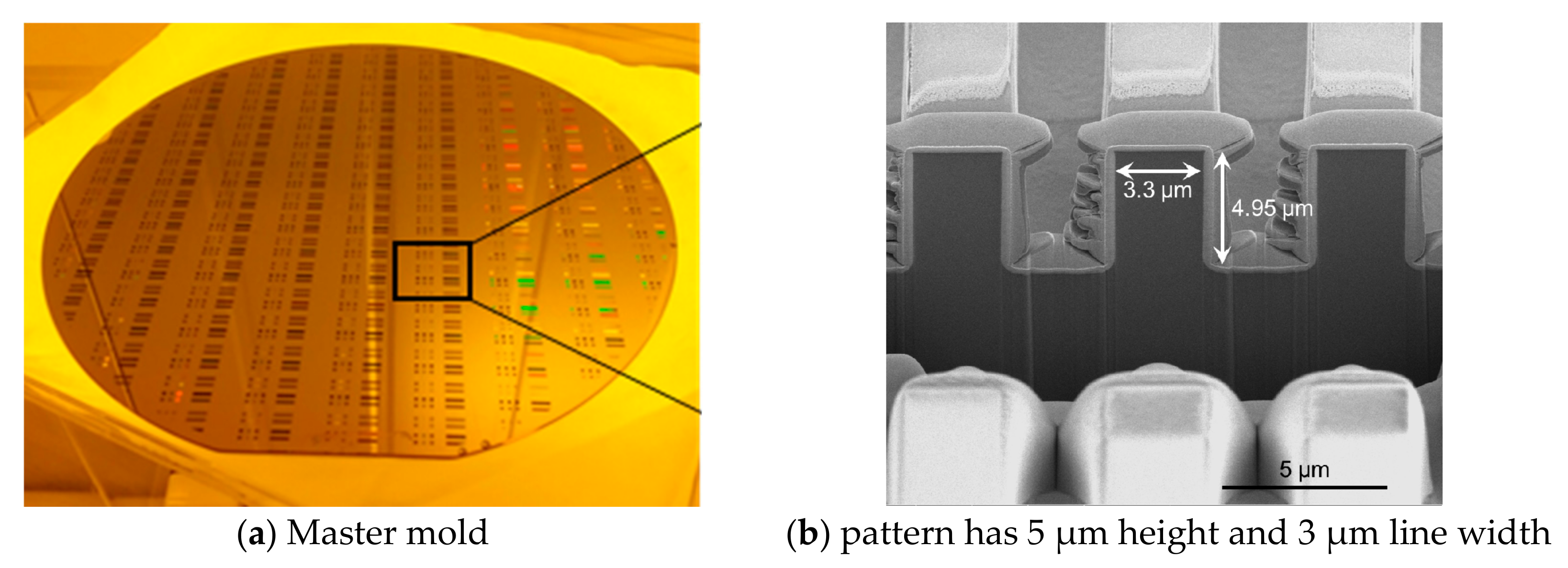
2.1. Master Mold Fabrication

A master mold with the desired pattern should be prepared for fabricating the flexible cliché. TFT gate patterns can be of various shapes, but we designed line patterns of various widths and angles because our focus was on minimizing the line width and improving the production speed. The pattern of the master mold has line widths of 2 μm, 3 μm, 5 μm, with line and space ratios of 1:1 and 1:2. The height of the pattern was maintained at 5 μm. These patterns were fabricated using an aligner that was cheap and easy to use, and the Si wafer was etched using reactive ion etching. Figure 1a shows the fabricated master mold and Figure 1b shows the fabricated pattern with an approximately 3-μm width line which is coated by Pt for measurement by a focused ion beam.

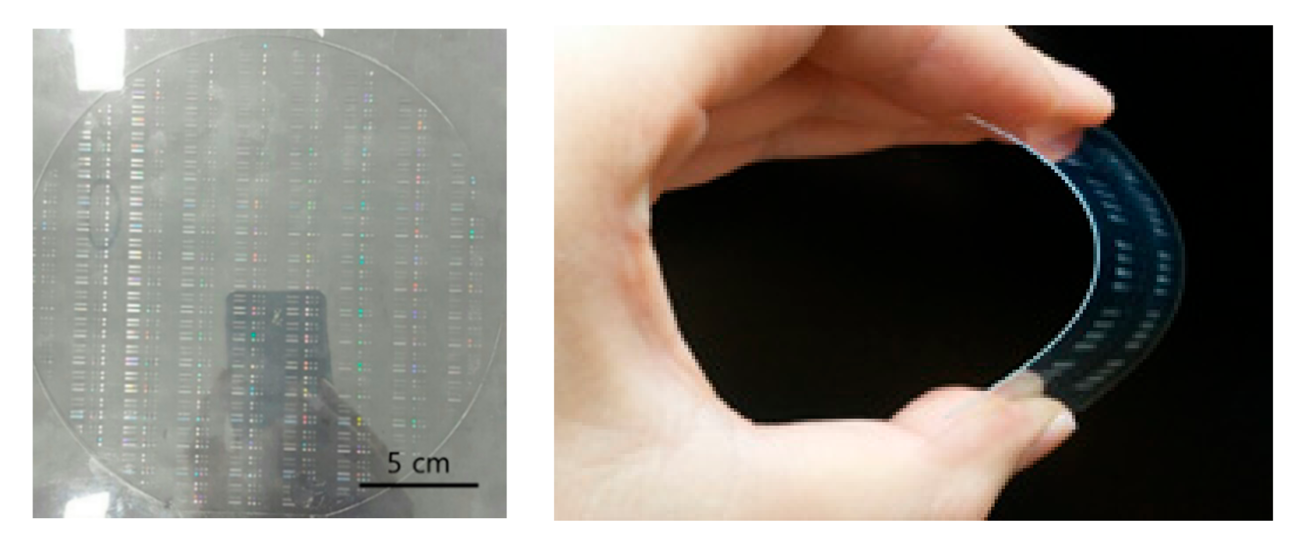
2.2. Fabrication of Cliché Using Various Resins

To increase the durability of the mold during repeated ultraviolet nanoimprint lithography (UV-NIL) processes and to separate the cliché smoothly, a surface treatment process to lower the surface energy was conducted. The coating process consisted of forming a self-assembled monolayer (SAM) on the surface of the master mold and reducing the surface temperature. The material used for this process was octadecyltrichlorosilane (OTS). The OTS coating process was carried out by vapor deposition in which the wafer was placed in a beaker, and OTS solution was vaporized using a hot plate kept at a temperature of 120 °C for one hour [20]. The entire process was carried out in an N2 atmosphere and the vaporized OTS was deposited on the master mold patterns.
After the releasing layer was coated on the surface of the master mold, the cliché was fabricated from UV curable resins using the NIL process. As the role of the cliché is to facilitate detachment of the ink from the blanket, it may be intuitively considered advantageous to make the adhesive force between the cliché and the ink larger than that between the blanket and the ink. In addition, the force with which the cliché pulls the ink must be greater than the cohesion force of the ink [17]. Considering the relationship between these adhesion and cohesion forces, it can be deduced that the ink tends to move away from the blanket toward the cliché as the surface tension of the cliché significantly differs from that of the blanket. To verify this assumption, various resins with different surface energies were selected and the surface energies of each cliché were calculated by contact angle measurements [21,22]. In detail, the ASTM D5946, water droplet transfer technique, was applied to measure the contact angle and the surface energy can be determined from the experimental contact angle and liquid surface tension based on Berthelot’s rule [23]. Table 1 lists the type of resins used in the experiment and the contact angle and the surface energy of the clichés made from each resin. The resins used in the experiments are all UV-curable poly-urethanacrylate (PUA) types and have different viscosities and surface energies by controlling other additional components. For comparison, the surface energies of glass, the Si wafer, PET film, and blanket used in our experiment are also given.
The NIL process used for cliché fabrication is as follows. The resin is dispensed on the coated master mold, a substrate is applied on it, and then the rolling process is performed for pressing, while maintaining a conformal contact. As a next step, when the pattern of the master is filled with resin, UV rays with a 365-nm wavelength are incident on it to harden it. The released substrate has the reversed pattern of the master mold. Figure 2 shows the fabricated flexible cliché. The pattern was not broken but remained stable even when the substrate was properly bent.

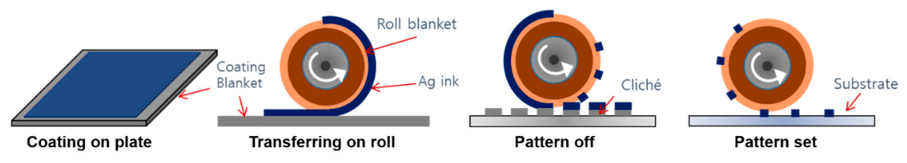
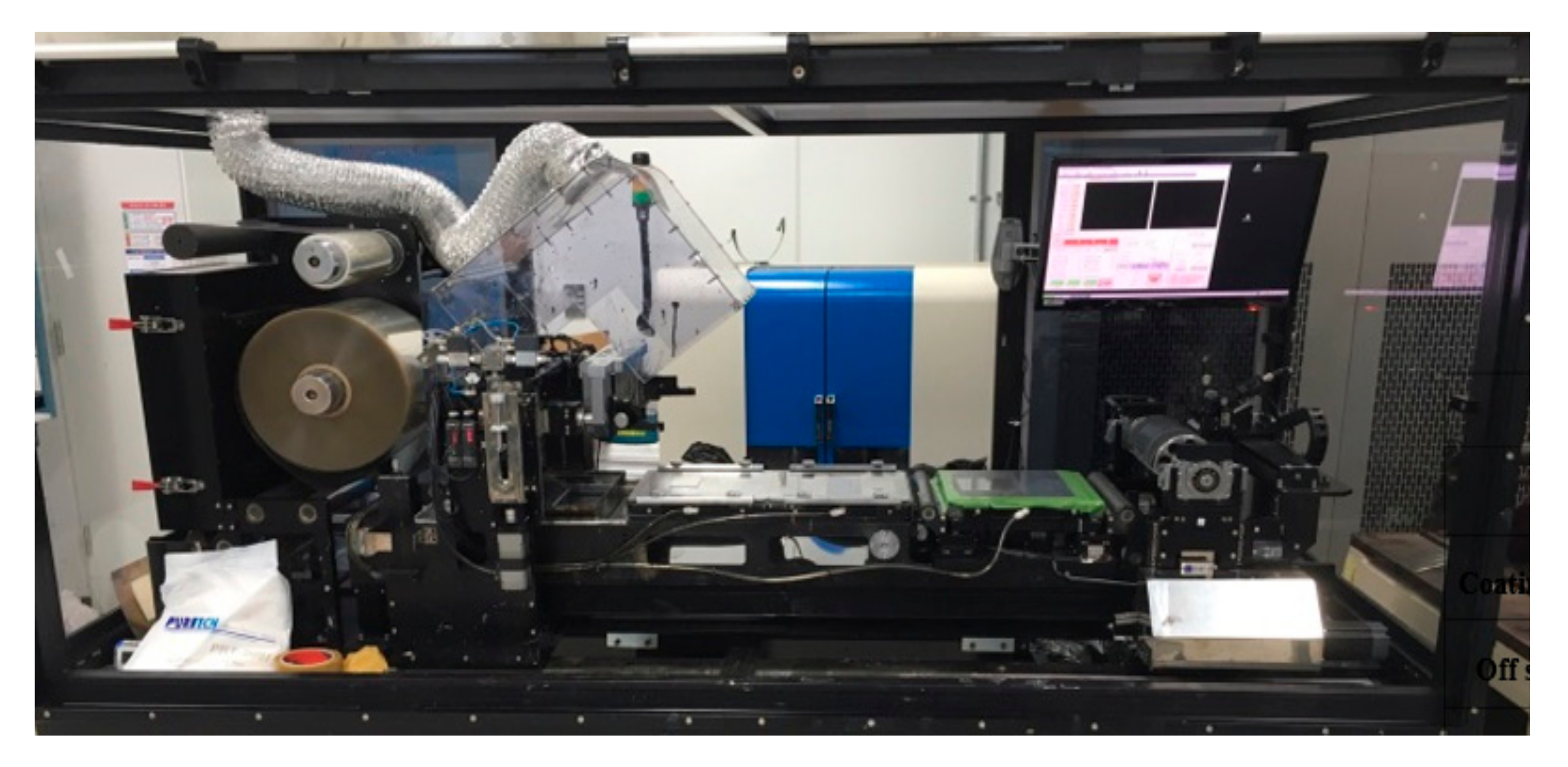
2.3. Reverse Offset Printing

The process of reverse offset printing used in this experiment is schematically explained in Figure 3. First, Ag nanoparticles containing ink are spin-coated on a substrate called the coating blanket. Then, the ink is transferred from the coating blanket to the roll blanket wrapped on a cylinder. Next, the roll blanket moves over the cliché with adequate pressure for patterning. Since the cliché has higher adhesion than the roll blanket, the Ag ink in the non-printed area is taken away from the roll blanket. Finally, the remaining Ag ink on the roll blanket is transferred to the final substrate by rolling and pressing, and the process is finished after drying the printed pattern in hot air. In reverse offset printing, the printing quality is determined by the adhesion and cohesion of the ink. At the off step by the cliché, the ink cohesion must be overcome by the adhesion to the blanket to have the ink cut at the edges of the patterns of the cliché [24,25]. The equipment used in this study is shown in Figure 4. The ink used in this experiment was ANP Ag ink which has 25 wt % of Ag particles, a viscosity of 1.5 cps, and a surface tension of 24.3 mN/m before spin-coating. In order for the cliché to detach the ink, the adhesive force between the cliché and the ink must be greater than the cohesion force of the ink. Cohesion is a physical property of a substance caused by the intermolecular attraction and it is one of the factors responsible for viscosity. Therefore, rheological properties, like viscosity of the ink, also have a large influence on the transfer. However, in this study, the solvent was evaporated because the ink was spin-coated at the first step, and the viscosity of the pattern off step is thereby significantly different from the original viscosity of the ink. To reduce this complexity, the type of ink was fixed and the printing experiments were carried out.
The off-speed ranged from 1 mm/s to 20 mm/s, while the set-speed was fixed at 5 mm/s. The printed pattern was examined using a microscope and we selected PUA1, PUA4, and PUA5 as representative resins to clarify the effect of the surface energy difference.

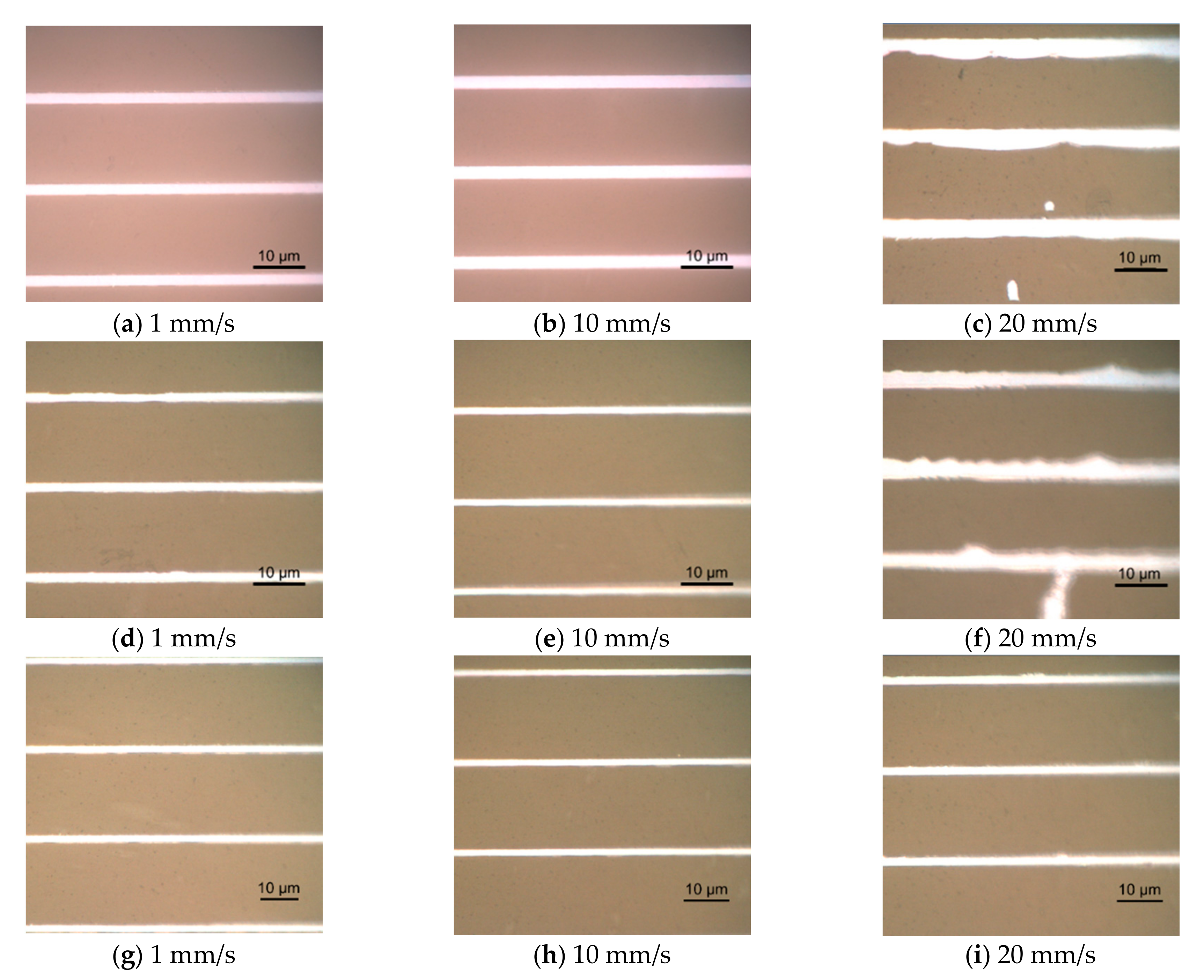
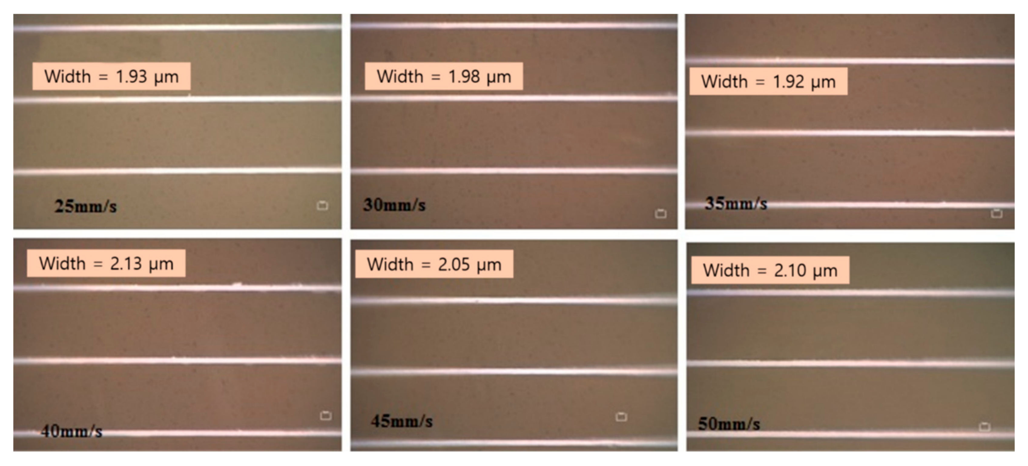
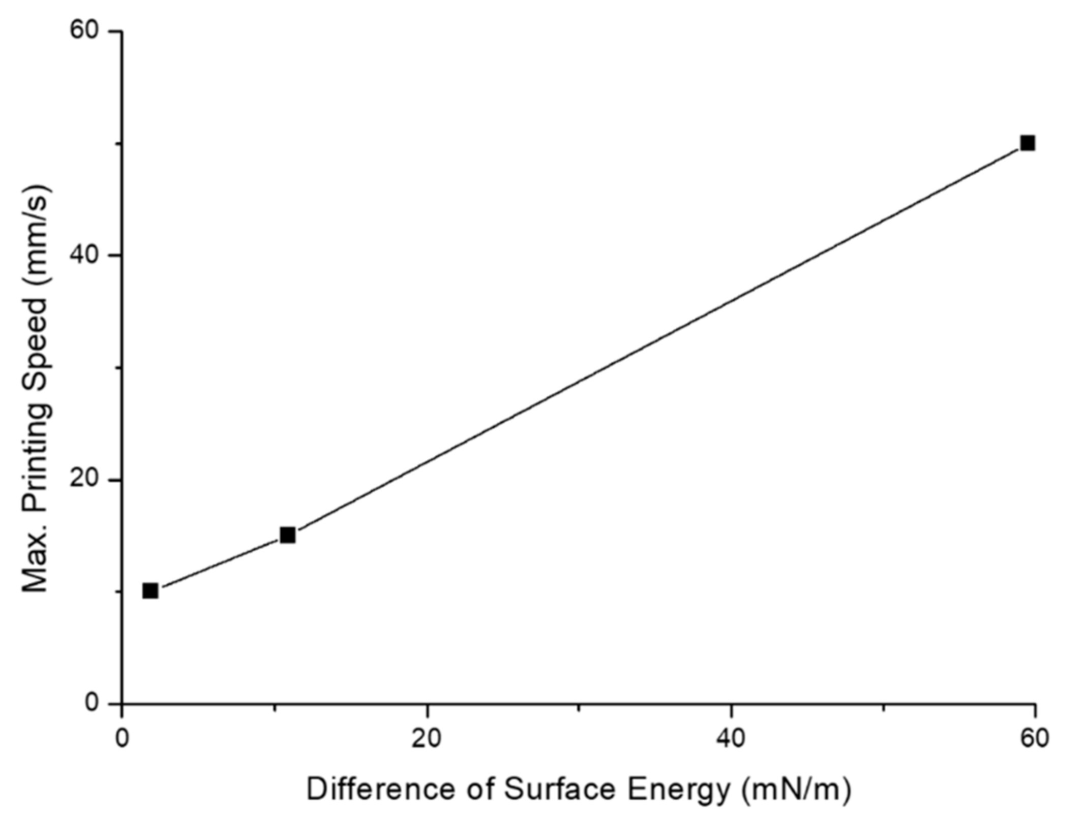
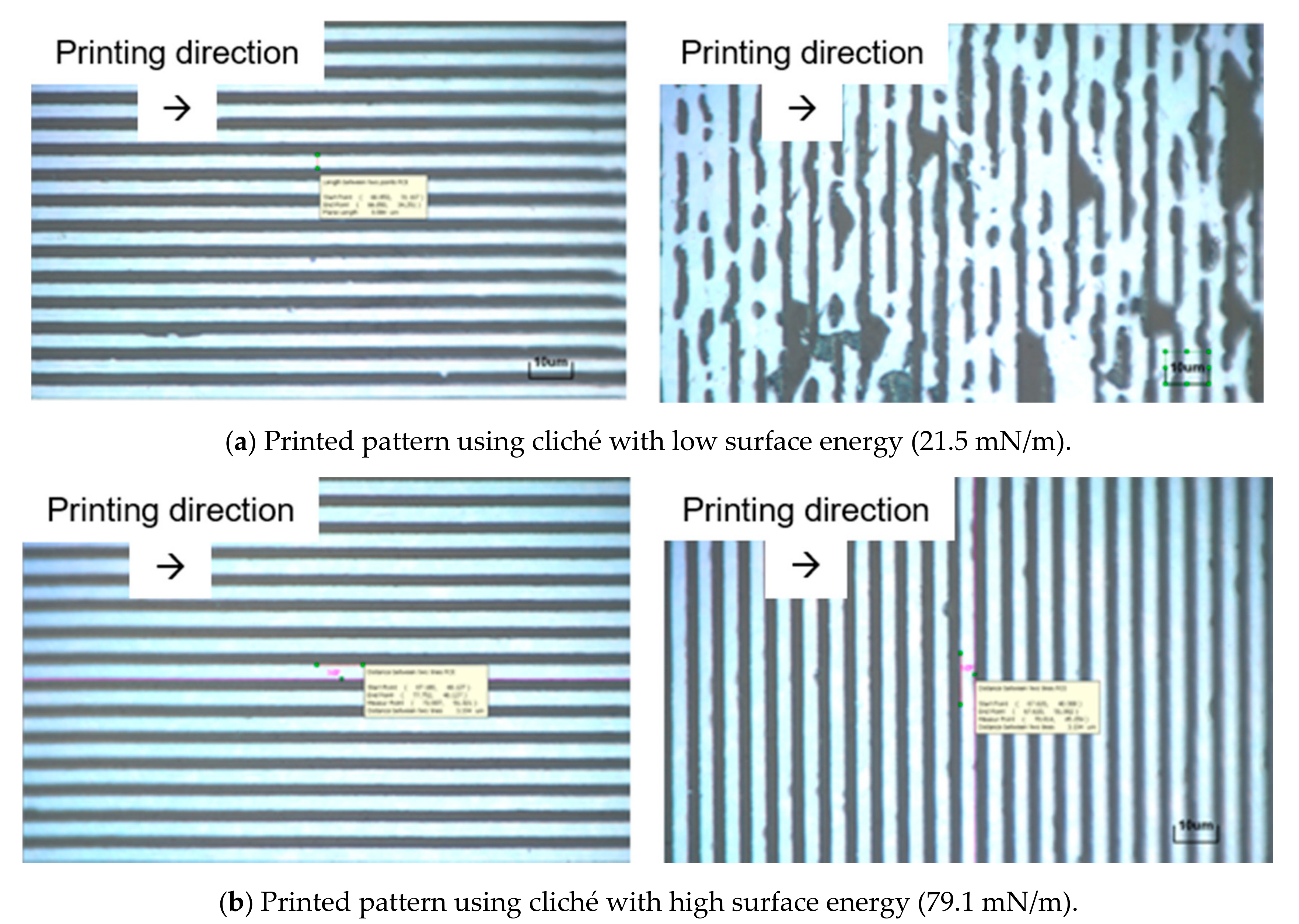
3. Results and Discussion

Figure 5 shows the printing patterns obtained at various off speeds for each resin. Referring to the process conditions when using glass- or Si-patterned clichés, the range of the normal printing speed to achieve fine patterns was set from 1 mm/s to 5 mm/s. At 1 mm/s, where the off-speed was slow, there was no significant change in the printing quality, irrespective of the resin used. However, as the off-speed increased to 10 mm/s and 20 mm/s, it was confirmed that a high printing quality could be obtained only when the resin with the highest surface energy was used as the cliché material. When the resin with a surface energy not significantly different from that of the blanket was used as the cliché material, the pattern off process was not effectively performed when the speed was increased. However, when PUA5 with a surface energy of 79.1 mN/m was used, which was considerably different from the surface energy of the blanket, the off process was effective at a high printing speed. Therefore, a high difference in the surface energies of the resin and blanket can enhance the printing speed. Figure 6 shows the results at a printing speed of 50 mm/s using the cliché with high surface energy. Although the speed is nearly 10 times faster than the conventional printing speed, the print quality does not show any sign of deterioration. The relationship between the maximum allowable printing speed and the surface energy difference is expressed by the graph shown in Figure 7. The larger the difference in the surface energy of the blanket and flexible cliché, the larger is the maximum allowable printing speed.
In addition, the printing quality varies depending on the angle between the movement direction of the roller and the pattern, which can also be explained by the relationship between the cohesion force and adhesion force of the ink and substrate. As shown in Figure 8a, if the direction of the roller is aligned with the direction of the pattern, the cliché detaches the ink easily because the amount of ink to be removed from the blanket at one time is relatively small. In addition, once separated ink has continuously encountered the pattern edge, detachment can occur easily, like crack propagation. However, if the direction of the roller is perpendicular to the direction of the pattern, it does not work well because a relatively large amount of ink should be detached from the blanket at one time. That is, in this case, the separation of the ink did not occur continuously, but the separation should be uniformly performed along a large width of the pattern edge. This angle dependency can be improved using a cliché having a high surface energy, as shown in Figure 8b. When a cliché with a surface energy of 79.1 mN/m was used, it was found that even if the direction of the pattern and the rolling were perpendicular to each other, the pattern detachment was efficiently performed and there was no problem in printing. Therefore, it can be concluded that it is effective to use a cliché having a high surface energy to form various patterns, such as the gate line of a TFT.

4. Conclusions

In this study, we confirmed the possibility of fabricating a flexible cliché that can replace the hard type in the reverse offset printing process using the nanoimprint process. In this study, various types of resins were tested to find ways to improve the printing speed and quality in fabricating fine patterns. When a cliché was fabricated using a material with a surface energy considerably different from that of the blanket, ink was easily and clearly detached from the blanket and transferred to the cliché. This confirms that the higher the surface energy of the cliché, the faster the printing speed. It was observed that productivity was 10 times higher when compared to the process using a hard cliché. In addition, to print various patterns, such as gate lines of TFTs, printing must be possible irrespective of the angle formed between the pattern and direction of the roller. When a flexible cliché is manufactured using a resin with a surface energy considerably different from that of the blanket, the ink can be detached easily and fine patterns can be engraved successfully regardless of the pattern shape. In conclusion, we developed a flexible cliché using a nanoimprint process with materials having a surface energy considerably different from that of the blanket and showed that the printing speed can be significantly increased and printing quality can be improved at the same time.

Acknowledgments

This research was supported by the Ministry of Trade, Industry and Energy (MOTIE), the Korea Institute for the Advancement of Technology (KIAT) through the Encouragement Program for The Industries of Economic Cooperation Region (N0002310), and was supported by a program of the Korea Institute of Machinery and Materials (NK202C) and was supported by the Basic Science Research Program through the National Research Foundation of Korea (NRF) funded by the Ministry of Science, ICT and Future Planning (NRF-2017R1A2B4008053).

Author Contributions

S.K., S.-H.L. and K.Y.K. conceived and designed the experiments; Y.J.K. and Y.J. performed the experiments; D.K. and T.M.L. manufactured the experimental system and analyzed the data; Y.T.C. and Y.J. wrote the paper; and Y.T.C. was involved in the design, experiment, and writing of paper as a whole.

Conflicts of Interest

The authors declare no conflict of interest.

References

  1. Tsumura, A.; Koezuka, H.; Ando, T. Macromolecular electronic device: Field‐effect transistor with a polythiophene thin film. Appl. Phys. Lett. 1986, 49, 1210–1212. [Google Scholar] [CrossRef]
  2. Burroughes, J.H.; Jones, C.A.; Friend, R.H. New semiconductor device physics in polymer diodes and transistors. Nature 1988, 335, 137–141. [Google Scholar] [CrossRef]
  3. Horowitz, G.; Fichou, D.; Peng, X.; Xu, Z.; Garnier, F. A field-effect transistor based on conjugated alpha-sexithienyl. Solid State Commun. 1989, 72, 381–384. [Google Scholar] [CrossRef]
  4. Garnier, F.; Hajlaoui, R.; Yassar, A.; Srivastava, P. All-polymer field-effect transistor realized by printing techniques. Science 1994, 265, 1684–1687. [Google Scholar] [CrossRef] [PubMed]
  5. Laquindanum, J.G.; Katz, H.E.; Lovinger, A.J.; Dodabalapur, A. Morphological origin of high mobility in pentacene thin-film transistors. Chem. Mater. 1996, 8, 2542–2544. [Google Scholar] [CrossRef]
  6. Dimitrakopoulos, C.D.; Mascaro, D.J. Organic thin-film transistors: A review of recent advances. IBM J. Res. Dev. 2001, 45, 11–27. [Google Scholar] [CrossRef]
  7. Yoshimura, Y.; Takeda, Y.; Fukuda, K.; Kumaki, D.; Tokito, S. High-speed operation in printed organic inverter circuits with short channel length. Org. Electron. 2014, 15, 2696–2701. [Google Scholar] [CrossRef]
  8. Fukuda, K.; Yoshimura, Y.; Okamoto, T.; Takeda, Y.; Kumaki, D.; Katayama, Y.; Tokito, S. Reverse‐Offset Printing Optimized for Scalable Organic Thin‐Film Transistors with Submicrometer Channel Lengths. Adv. Electron. Mater. 2015, 1. [Google Scholar] [CrossRef]
  9. Subramanian, V.; Fréchet, J.M.; Chang, P.C.; Huang, D.C.; Lee, J.B.; Molesa, S.E.; Murphy, A.R.; Rendinger, D.R.; Volkman, S.K. Progress toward development of all-printed RFID tags: Materials, processes, and devices. Proc. IEEE 2005, 93, 1330–1338. [Google Scholar] [CrossRef]
  10. Kunnari, E.; Valkama, J.; Keskinen, M.; Mansikkamäki, P. Environmental evaluation of new technology: Printed electronics case study. J. Clean. Prod. 2009, 17, 791–799. [Google Scholar] [CrossRef]
  11. Gaikwad, A.M.; Steingart, D.A.; Nga Ng, T.; Schwartz, D.E.; Whiting, G.L. A flexible high potential printed battery for powering printed electronics. Appl. Phys. Lett. 2013, 102. [Google Scholar] [CrossRef]
  12. Li, Z.; Zhang, R.; Moon, K.S.; Liu, Y.; Hansen, K.; Le, T.; Wong, C.P. Highly Conductive, Flexible, Polyurethane‐Based Adhesives for Flexible and Printed Electronics. Adv. Funct. Mater. 2013, 23, 1459–1465. [Google Scholar] [CrossRef]
  13. Nguyen, P.Q.; Yeo, L.P.; Lok, B.K.; Lam, Y.C. Patterned surface with controllable wettability for inkjet printing of flexible printed electronics. ACS Appl. Mater. Interfaces 2014, 6, 4011–4016. [Google Scholar] [CrossRef] [PubMed]
  14. Søndergaard, R.R.; Hösel, M.; Krebs, F.C. Roll‐to‐Roll fabrication of large area functional organic materials. J. Polym. Sci. Part B Polym. Phys. 2013, 51, 16–34. [Google Scholar] [CrossRef]
  15. Lee, T.M.; Noh, J.H.; Kim, C.H.; Jo, J.; Kim, D.S. Development of a gravure offset printing system for the printing electrodes of flat panel display. Thin Solid Films 2010, 518, 3355–3359. [Google Scholar] [CrossRef]
  16. Grau, G.; Kitsomboonloha, R.; Subramanian, V. Fabrication of a high-resolution roll for gravure printing of 2 µm features. Proceeding of SPIE Organic Photonics and Electronics, San Diego, CA, USA, 31 August 2015. [Google Scholar]
  17. Choi, Y.M.; Lee, E.; Lee, T.M. Mechanism of reverse-offset printing. J. Micromech. Microeng. 2015, 25, 075019. [Google Scholar] [CrossRef]
  18. Kim, M.; You, I.K.; Han, H.; Jung, S.W.; Kim, T.Y.; Ju, B.K.; Koo, J.B. Organic thin-film transistors with short channel length fabricated by reverse offset printing. Electrochem. Solid-State Lett. 2011, 14, H333–H336. [Google Scholar] [CrossRef]
  19. Kang, D.; Lee, E.; Kim, H.; Choi, Y.M.; Lee, S.; Kim, I.; Yoon, D.; Jo, J.; Kim, B.; Lee, T.M. Investigation on synchronization of the offset printing process for fine patterning and precision overlay. J. Appl. Phys. 2014, 115, 234908. [Google Scholar] [CrossRef]
  20. Jeong, Y.; Shin, S.; Choi, H.; Kim, S.; Kim, J.; Kwon, S.; Kim, K.Y.; Lee, S.; Jung, Y.G.; Cho, Y.T. Fabrication of Nano-Micro Hybrid Structures by Replication and Surface Treatment of Nanowires. Crystals 2017, 7, 215. [Google Scholar] [CrossRef]
  21. Johnson, K.L.; Kendall, K.; Roberts, A.D. Surface energy and the contact of elastic solids. Proc. R. Soc. Lond. A Math. Phys. Eng. Sci. 1971, 324, 301–313. [Google Scholar] [CrossRef]
  22. Lehr, C.M.; Bouwstra, J.A.; Boddé, H.E.; Junginger, H.E. A surface energy analysis of mucoadhesion: Contact angle measurements on polycarbophil and pig intestinal mucosa in physiologically relevant fluids. Pharm. Res. 1992, 9, 70–75. [Google Scholar] [CrossRef] [PubMed]
  23. Kwok, D.Y.; Neumann, A.W. Contact angle measurement and contact angle interpretation. Adv. Colloid Interface Sci. 1999, 81, 167–249. [Google Scholar] [CrossRef]
  24. Choi, Y.M.; Lee, E.S.; Lee, T.M.; Kim, K.Y. Optimization of a reverse-offset printing process and its application to a metal mesh touch screen sensor. Microelectron. Eng. 2015, 134, 1–6. [Google Scholar] [CrossRef]
  25. Chang, J.; Lee, S.; Lee, K.B.; Lee, S.; Cho, Y.T.; Seo, J.; Lee, S.; Jo, G.; Lee, K.; Kong, H.; et al. Overlay accuracy on a flexible web with a roll printing process based on a roll-to-roll system. Rev. Sci. Instrum. 2015, 86, 055108. [Google Scholar] [CrossRef] [PubMed]
Figure 1. Silicon master mold with a line and space pattern for the UV-NIL process to fabricate the cliché.
Applsci 07 01302 g001
Figure 2. Fabricated flexible cliché using UV-curable resin by the NIL process.
Applsci 07 01302 g002
Figure 3. The schematic explanation of reverse offset printing process.
Applsci 07 01302 g003
Figure 4. Reverse offset printing equipment used in this experiment.
Applsci 07 01302 g004
Figure 5. Results for printed pattern with 2-μm line width in reverse offset printing: (a) 1 mm/s, (b) 10 mm/s, and (c) 20 mm/s printing speed using PUA1 (surface energy: 21.5 mN/m); (d) 1 mm/s, (e) 10 mm/s, and (f) 20 mm/s printing speed using PUA4 (surface energy: 30.5 mN/m); and (g) 1 mm/s, (h) 10 mm/s, and (i) 20 mm/s printing speed using PUA5 (surface energy: 79.1 mN/m).
Applsci 07 01302 g005
Figure 6. Results for the printed pattern with a 2-μm line width in reverse offset printing using PUA5 resin as the cliché material with the highest surface energy (79.1 mN/m) at printing speeds ranging from 25 mm/s to 50 mm/s.
Applsci 07 01302 g006
Figure 7. Maximum allowable printing speed according to the surface energy difference between the blanket and the flexible cliché.
Applsci 07 01302 g007
Figure 8. Angle dependency of printed pattern using cliché fabricated from different resins.
Applsci 07 01302 g008
Table 1. Contact angles and surface energies of various resins used to fabricate cliché and other materials for comparison.
PUA1PUA2PUA3PUA4PUA5GlassPETBlanket
C.A. (°)101.590.385.7685.323.6452.743109.5
S.E. (mN/m)21.5125.6330.830.579.1153.6359.819.6

