The Use of Heat-Resistant Concrete Made with Ceramic Sanitary Ware Waste for a Thermal Energy Storage


1
Faculty of Fire Safety Engineering, The Main School of Fire Service, 52/54 Słowackiego Str., 01-629 Warsaw, Poland
2
Faculty of Natural Sciences, Siedlce University of Natural Sciences and Humanities, 2 Stanisława Konarskiego Str., 08-110 Siedlce, Poland
3
Faculty of Civil Engineering and Architecture, Lublin University of Technology, 40 Nadbystrzycka Str., 20-618 Lublin, Poland
*
Author to whom correspondence should be addressed.
Appl. Sci. 2017, 7(12), 1303; https://0-doi-org.brum.beds.ac.uk/10.3390/app7121303
Submission received: 17 November 2017
/
Revised: 9 December 2017
/
Accepted: 14 December 2017
/
Published: 16 December 2017
(This article belongs to the Section Materials Science and Engineering)
Abstract
:The paper presents the results obtained in the course of a study on the concrete made of aggregate obtained from wastes of sanitary ceramics. Previous examinations proved high in strength and durability of concrete of this type, and it showed a resistance to high temperatures. The material was classified as a fireproof concrete. While searching for the optimal applications of such concrete, a series of examinations and analyses on its thermal energy storage (TES) properties were performed. This paper describes the two-stage experiment on the thermal behavior of the concrete made with sanitary ceramic wastes during cooling processes in comparison to different building materials subjected to the same thermal conditions. On the basis of the thermal, infrared analysis, and suitable calculations, the thermal power and the ability of the composite to store thermal energy was estimated. Finally, it was stated that the concrete made of sanitary ceramic waste aggregate and alumina cement can be recommended as a heat-accumulating material, and in combination with high durability can be used, e.g., for the construction of fireplace bodies.
1. Introduction
The increase in the usage of concrete around the world is associated with the increased demand for raw materials necessary for its production. Reuse of waste materials as building materials is particularly important in order to reduce energy consumption and the use of natural resources, with respect to the 4R principle (Reduce-Reuse-Recover-Recycle) [1]. The use of waste materials as construction materials helps to protect the environment by supporting the reduction of greenhouse gas emission and the consumption of natural resources, and it also leads to cost reductions [2,3]. Changing the mentality of society and engineers will allow treating the waste not only as an environmental issue, but also as an important source of industrial raw materials. Introducing the idea of the closed-loop economy that involves closing the product’s life-cycle may result in a reduction in the amount of waste that needs to be deposited in landfills [4,5,6].
It is increasingly accepted to use green concretes in construction because of their numerous advantages. Green concretes offer many environmental, technical, and economic benefits (similar to the high performance concretes—HPC), such as high strength, increased durability, increased usability, reduced permeability, and excellent acid resistance. However, not all green concretes can be considered as HPCs. The properties listed are responsible for faster production of concrete, shortening of curing time, construction cost reduction, early termination of the project, maintenance cost reduction, and longer building service life. Green concretes promote sustainable and innovative use of waste materials and unconventional alternative materials [7,8]. One of these materials is a recycled aggregate based on ceramic sanitary wastes, which are often called white ceramics.
In the research conducted by [9] three types of coarse ceramic aggregate were used: crushed floor and wall tiles, as well as sanitary ceramics. The aggregate was introduced into the mix in a proportion of 20–100%. The results of the research show that it is possible to completely replace the coarse aggregate with the recycled ceramic aggregate. In other studies [10], concrete was tested, which was made solely of the ceramic aggregate derived from wall tiles. Cylindrical samples 100 mm in diameter, and 150 mm cubic-shape specimens were formed, and then they were stored in accordance with the standard requirements. The concrete’s compressive strengths after 3, 7, 14, and 28 days of maturing were determined. The results showed that the strength of the ceramic concrete increased with age considerably more than for concrete made of the natural aggregates. Additionally, in [11] it was shown that by replacing 20–25% of the gravel aggregate with the crushed sanitary ceramics, the concrete’s strength can be increased with respect to the traditional concrete. In addition to the strength tests, other features of the ceramic concrete were also investigated, e.g., the depth of water penetration. The results showed no difference in relation to the conventional concrete.
Studies [12] confirm that the use of the ceramic coarse aggregate in an amount of 30% improves the physical and mechanical properties of the concrete. The results of other studies [12,13,14,15,16,17,18] also confirm the usefulness of the ceramics as the recycled aggregate to concrete. The authors defined guidelines for the design of the non-structural and the structural concretes of a high strength. One of the directions is the production of the refractory and the heat-resistant concretes obtained on the basis of the sanitary ceramic waste material.
Attempts were also made to use a ceramic powder as a cement additive. In studies [19], the cement was replaced in amounts of 0%, 5%, 10%, and 20% of the ceramic powder. Despite maintaining the mixture’s physical parameters at higher amounts of the ceramic powder, a small decrease in strength of the concrete was observed. The optimum, from the point of view of the mixture’s workability and the concrete’s strength, was an addition in amounts not exceeding 15%. Similar studies were conducted [20,21,22], in which 10–40% of ceramic powder as a substitute for cement was used. It has been shown that such concrete has high strength and durability. At the same time, the powder did not cause any negative effects on the cement hydration process. Additionally, the pozzolanic activity of the mixtures with the ceramic powder was determined. Mortar samples were made in which 25% of the cement was replaced with ceramic powder. A comparison was performed only on samples containing the cement. The pozzolanic activity index tested for mortars after 28 days was 71%, and after 90 days was 74.5%. These values were lower than the standard requirements for fly ash (75% and 85%, respectively), thus, the pozzolanic activity of the ceramic powder was low.
In papers [13,23,24,25,26,27] the authors present the results of research on the recycled concrete, with resistances to high temperatures exceeding 1000 °C. The basic properties of the concrete mixture have been investigated, as well as the compressive and tensile strengths. Concretes based solely on the recycled aggregate, the Portland cement, and the alumina cement were performed. Researchers have also shown that the use of an aeration admixture effectively reduces the phenomenon of the concrete’s thermal spalling, which contributes to the increased safety of the structure in terms of a fire resistance. At the same time, the 10% aerated concrete achieved higher strength and the lower strengths drops during the heating up to 1000 °C, compared to the concrete without the aeration admixture [26].
When analyzing the research results on the use of a recycled aggregate in the form of crushed bricks and hollow bricks (the red ceramics) [28,29,30,31] it must be concluded that the results obtained are contradictory. Some researchers report that the physical and strength parameters of concretes with the red ceramics do not differ significantly from the conventional concretes. In most cases, the authors affirm the negative effect of the use of the red ceramics as the concrete’s aggregate. Much more favorable results are obtained with regard to the white ceramics, including the sanitary ceramics.
The research described in this paper is a continuation of the authors own studies presented in [25]. The results indicate that the recycled refractory concrete may have the ability to accumulate heat energy (thermal energy storage—TES), which is associated with new methods of its potential use, e.g., for the fireplace body. In this study selected materials have been investigated in the two-stage experimental program, with the results allowing the determination of the thermal power of the fireproof concrete with the ceramic aggregate. In order to estimate the initial TES properties samples were subjected to a low temperature load at 230 °C (first stage). Next, the materials were tested in the operational temperature of a fireplace (400 °C), and they were examined in order to determine the degree of the materials’ degradation. Conclusions were drawn, which indicate that recycled, fireproof concrete made with the ceramic waste aggregate can be successfully used to the construction of the fireplace body.
Analysis of the thermal parameters of various types of concrete is subjected to a number of studies [32,33,34,35,36], the results of which indicate the possibility of using the cement composite as the TES material. In addition, finding new methods to deposit ceramic wastes have a double positive impact on the environment. Firstly, currently stored wastes will be consumed, and secondly, the consumption of natural aggregates will decrease.
2. Thermal Energy Storage in Building Issues
A common feature of the TES materials is the ability to absorb, store, and exchange heat energy [37]. Among the issues of the building physics, the phenomenon of TES is considered as the ability to absorb and store the particular portion of heat, which can be later exchanged by the material. In the construction sector, such an effect is mainly used for heating issues with special attention to absorption and storage of the energy surpluses during hot periods, and its utilization during its shortage. The example of this situation can be in summer heat accumulators, which exchange the heat accumulated in the summer during the winter period.
From the point of view of the building physics, the attempts to store excessive energy inside the fireplace hearth are similar. The energy is usually exhausted into the atmosphere by the chimney together with fumes, but the aim is to store and use this energy for heating after the fireplace is damped down. The example of such a solution can be the Scandinavian fireplace made of natural stone that is characterized by a high heat accumulation ability. In this type of fireplace, with the applied technical solutions and the TES ability , the hearth temperature reaches about 1000 °C (normally it reaches 400 °C), which enables the fumes to burn down (soot burning). Excessive heat is accumulated in the solid body of the fireplace and consecutively exchanged even after the oven is extinguished. The exhaust gases are cool and clean, which has a positive impact on the environment. This type of technical solution requires specific materials used in their construction.
The Scandinavian fireplace is made of the natural steatite stone—a mineral that is a rare resource. Its treatment, to obtain the appropriate forms, is also difficult and expensive. The comparison of high temperature resistance of the mentioned mineral, derived from research [13], to the recycled concrete made of ceramic waste materials showed some resemblance between these materials. A concrete advantage is the ease of forming any shape. An economic consideration encouraged the authors to perform the research aimed at verifying the possibility of using concrete for the TES issues.
3. Thermal Transformations and Parameters Describing the TES Phenomena
The physical thermal transformations associated with the TES process, regardless of prevailing conditions, occur according to specific rules. They are systematized as shown:
- the amount of heat given out by the body is equal to the amount of heat absorbed by the environment of the body during the cooling,
- the amount of heat stored by the body during its heating is equal to the heat removed from the body during cooling (only if two changes occur in the same temperature range),
- the amount of heat ΔQ stored by the body during its heating or removed during the cooling is proportional to the body’s weight m and the difference of the body temperature ΔT before and after the thermal conversion; this rule can be written as:
The c parameter in Equation (1) is called as the specific heat. A simplified, commonly-quoted definition of this quantity is: the specific heat is the energy which enhances (or decreases) the temperature of a unit mass body by a unit temperature.
Another parameter which characterizes materials in terms of the thermal properties is the heat capacity. Its value b is calculated using the specific heat c and density of the material ρ of which the body is made:
The heat capacity is, therefore, the amount of the energy which is adopted while heating, or returned while cooling by 1 m3 of the material, changing its temperature by one degree. Alternatively, the heat capacity is the energy which lifts (or decreases) the temperature of the unit volume material, by a unit temperature.
Table 1 shows the values of the specific heat, density, and the heat capacity of various materials, including building materials. It can be stated that the best TES materials are not the materials of the highest bulk density—metals with bulk density of 7000–9000 kg/m3 are characterized by an average heat capacity of approx. 1.5 to 3.5 MJ/(m3∙K). The very good heat capacity, at low density, shows water at approx. 4.2 MJ/(m3∙K), and at even lower density, benzene (15.1 MJ/(m3∙K)). Granite, used as an aggregate in concrete, has a lower heat capacity than metals. Brick and river sand show even less heat capacity, at approx. 1.2 MJ/(m3∙K).
The heat capacity value is not sufficient to describe the maximum energy that can be stored in a unit volume of the material. In Equation (1), the ΔT is the difference between the temperature to which the body was heated, and the initial temperature before heating; assuming that the base temperature is room temperature, and the final temperature, a maximum temperature, to which the material can be heated, the heat accumulation capacity bmax can be calculated:
Calculations of the heat accumulation capacity of different materials were performed and are presented in Table 2. The maximum temperatures for materials listed were read from their technical sheets. These are the temperatures at which the materials maintain the invariability of shape, form, and physical state. This value for the heat resistant concrete was adopted in accordance with [13]; no destructive processes were observed at this temperature. It is easy to note that the ability to store the maximum amount of heat in a material’s volume, to a very large extent, depends not so much on the material’s heat capacity, as on its resistance to high temperatures.
Another parameter that determines whether the TES material will provide long-lasting comfort is the time of reflecting back (emission) of a stored energy. At a certain heat accumulation capacity, the emission time cannot be too short (then in the unit of time, too much heat is reflected back), or too long (then in the unit of time, too small heat is reflected back, e.g., insufficient to heat a room). A parameter, which binds the heat emission and time of this emission is the thermal power, is defined by the relationship:
where:
- P: thermal power,
- ΔQ: heat emission, and
- T: time of emission.
4. Experimental Program
4.1. Materials Used
Ten samples with dimensions of 4 × 4 × 16 cm (±0.2 cm), made of different building materials, were performed; steel (S), aerated concrete (AC), sand-lime brick (SLB), ceramic brick (CB), fireclay brick (FB), and four concretes: with gravel aggregate and Portland cement (CGA-PC), with gravel aggregate and alumina cement (CGA-AC), with ceramic aggregate and Portland cement (CCA-PC), with ceramic aggregate and alumina cement (CCA-AC), and granite (G). The samples were prepared in the majority by excision of the building elements (blocks, bricks, cobblestones). Concrete samples were molded in steel molds.
The steel sample was cut from a full bar with dimensions of 40 × 40 × 12,000 mm. The quality of the steel, designated according to EN 10025-2:2004, was defined as S 355 J2.
The sample of aerated concrete was cut using a saw with a diamond disc, from a block with dimensions of 240 × 240 × 590 mm. The density of the block was 700 kg/m3, compressive strength was 4 MPa, thermal conductivity was 0.7 W/(m2∙K), and the open porosity was 28.1%.
The sand-lime brick sample was cut from the product—a brick with dimensions 250 × 120 × 65 mm. Its density was equal to 1800 kg/m3, its thermal conductivity was 0.8 W/(m2∙K), and its open porosity was 15.4%.
The sample of ceramic brick was obtained from a solid brick of dimensions 250 × 120 × 65 mm. The material’s water absorption is no higher than 16%, its compressive strength was 15 MPa, its frost resistance was as for bricks of the 10 MPa class, and its open porosity was 16.9%.
The fireclay brick sample was cut from a full brick. The material has a minimum compressive strength of 30 MPa, an operational temperature of 1370 °C, an open porosity of 20%, and an apparent density of 2.1 g/cm3.
The granite rock sample was obtained from a rock block. A diamond disc was used for its preparation. The material has a specific density of 2.8 g/cm3, a bulk density of 2.7 g/cm3, a compressive strength of 59 MPa, a modulus of elasticity of 360 GPa, water absorption of 0.8%, and open porosity of 2.2%.
The concretes’ compositions used in the tests, as well as their basic properties, are described in the Section 4.3.
4.2. Aggregate Properties
Two types of aggregates were used to the concretes production: traditional—gravel (mainly granite), and recycled—made of white ceramics. The recycled aggregate used in the study was prepared on the basis of a post-production waste of sanitary ceramics [13]. Aggregate crushers were used to prepare the aggregate, allowing for the separation of the fine fraction (0–4 mm), which passed through a 4 mm sieve and the coarse fraction (4–8 mm), grains which remained in the 4 mm sieve, but passed through a sieve with a mesh of 8 mm. The coarse aggregate that remained in the 8 mm sieve were crushed again. The properties of the aggregates used are summarized in Table 3.
4.3. Mixtures and Properties of Concretes
Two cements were used in the concrete mix production. The first one was the Górkal 70 high alumina cement (Al2O3 content: 69–71%). This cement is recommended for use in concretes and mortars that are exposed to high temperatures. Declaration of the cement’s performance indicates the possibility of manufacturing composites, which can operate in a temperature of 1560 °C. The second cement used was the CEM I 42,5N—SR 3/NA Portland cement, which has stable physicochemical properties, suitable binding time, high early and final strength, low alkali content, and high resistance to aggressive chemicals; these features lead to the cement being commonly used in industrial concrete production. The basic parameters of both cements are shown in Table 4.
Four types of concrete were performed:
- with gravel aggregate and Portland cement: CGA-PC,
- with gravel aggregate and alumina cement: CGA-AC,
- with ceramic aggregate and Portland cement: CCA-PC, and
- with ceramic aggregate and alumina cement: CCA-AC.
All of the concretes had the same proportions of components as shown in Table 5.
Basic features of the concretes, such as bulk density, water absorption, and compressive strength (Table 6), were determined. Tests were performed after 28 days of maturing. The results obtained are the arithmetic average of six samples.
4.4. Tests and Methodology
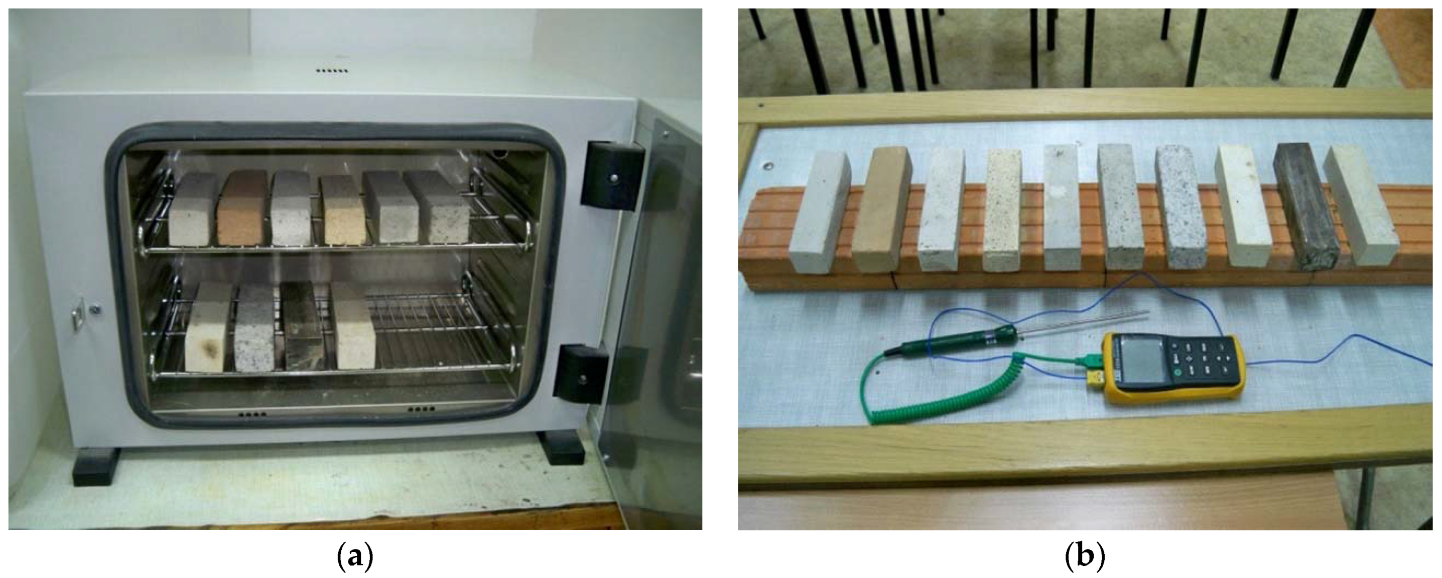
A two-stage experiment was designed. The aim of the first stage was to estimate the initial TES abilities of the selected materials including the fireproof concrete (with the ceramic aggregate). The test stand was equipped with a ceramic base, an electronic thermometer, and a laboratory dryer, which can heat the specimens to a temperature of 230 °C.
The room temperature was 25.4 °C. Samples were placed in the laboratory dryer and its maximum working temperature (230 °C) was set. The dryer reached the temperature after one hour and 15 min. At this temperature, the specimens were placed for three hours, after which they were removed from the dryer and laid upon a ceramic base. The samples’ temperature was measured using a digital thermometer by applying a probe to the surface of the sample in the middle of its length. The samples used in the experiment, together with the test stand, are shown in Figure 1. On the basis of the results obtained, the materials’ thermal power was calculated, using Equations (1) and (4).
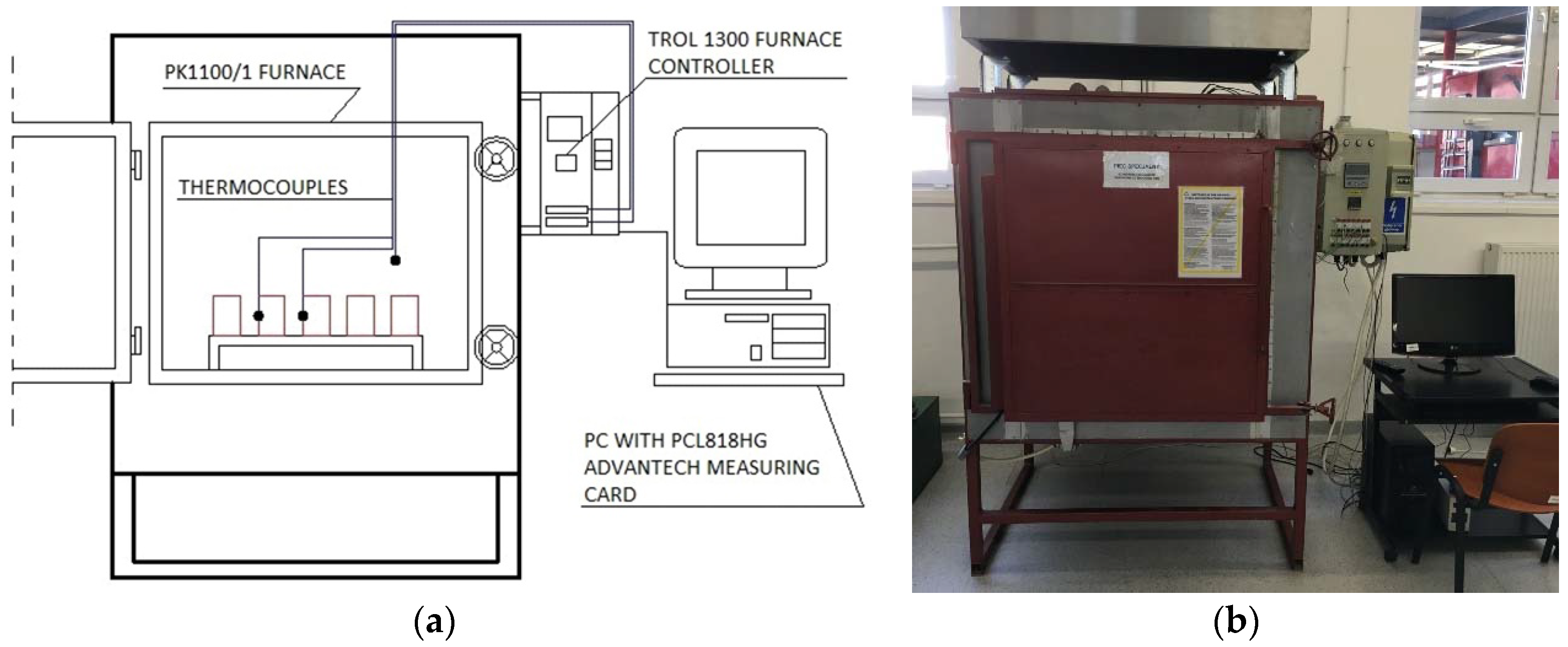
The second stage was a re-run of the experiment, but it was assumed to heat the samples to the temperature similar to these prevailing in the fireplace. The aim was to assess the thermal power in the operational temperature range of the fireplace. The test stand was equipped with the PK 1100/1 furnace (Thermolab S.C, Warsaw, Poland), which was controlled by a PC, and the infrared camera (Flir, Boston, MA, USA) was a FLIR123 model. The thermocouples, which are an integral part of the furnace, were used to measure the temperatures. The readings from the thermocouples were recorded on the PC. The scheme and the furnace are shown in Figure 2.
The samples tested were the same as the ones used during the first stage of the TES assessment. The specimens, after placing them in the furnace, were subjected to a relatively rapid temperature increase, i.e., within half an hour, the furnace was heated to a temperature of 400 °C. The samples remained for 30 min in the closed furnace. After switching off the heating mechanism, the furnace’s doors were opened in order to provide the possibility of the heat emission by the samples. Using the thermocouples installed on the samples, the surface temperature was measured.
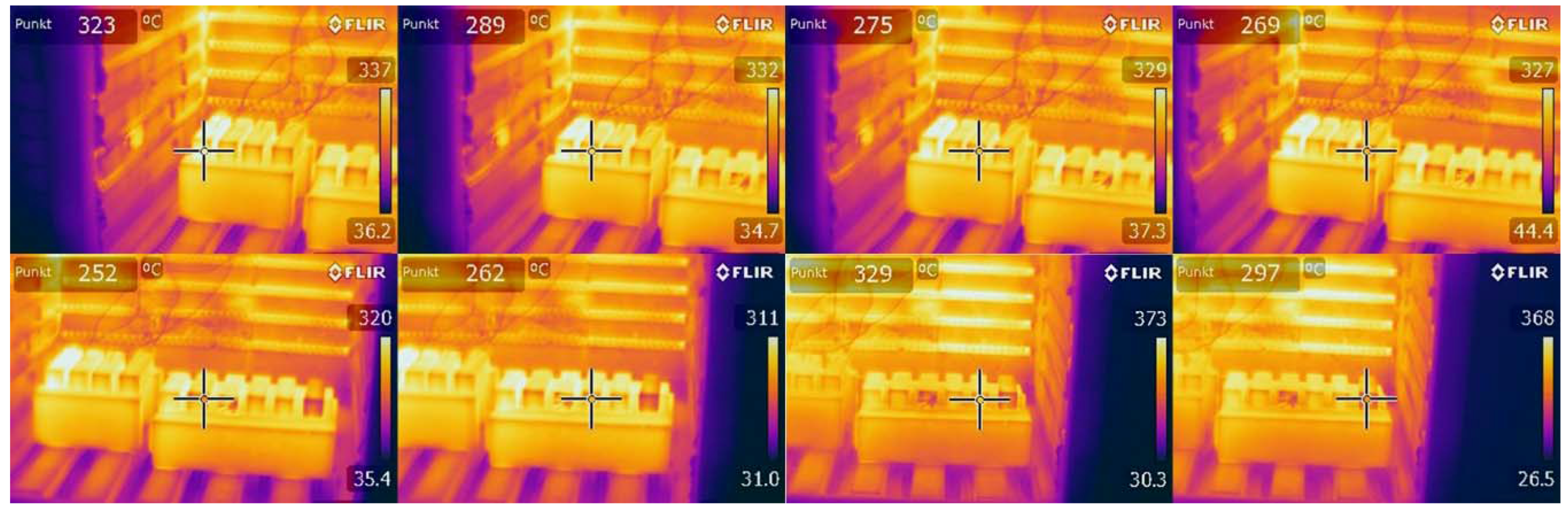
During the cooling process, at five-minute intervals, the infrared images were taken by a thermal imaging camera on which all the samples could be seen. Sample images after 3 min of cooling are shown in Figure 3.
5. Results and Discussion
5.1. Stage 1—Initial Assesment of the TES Properties at Lower Temperature
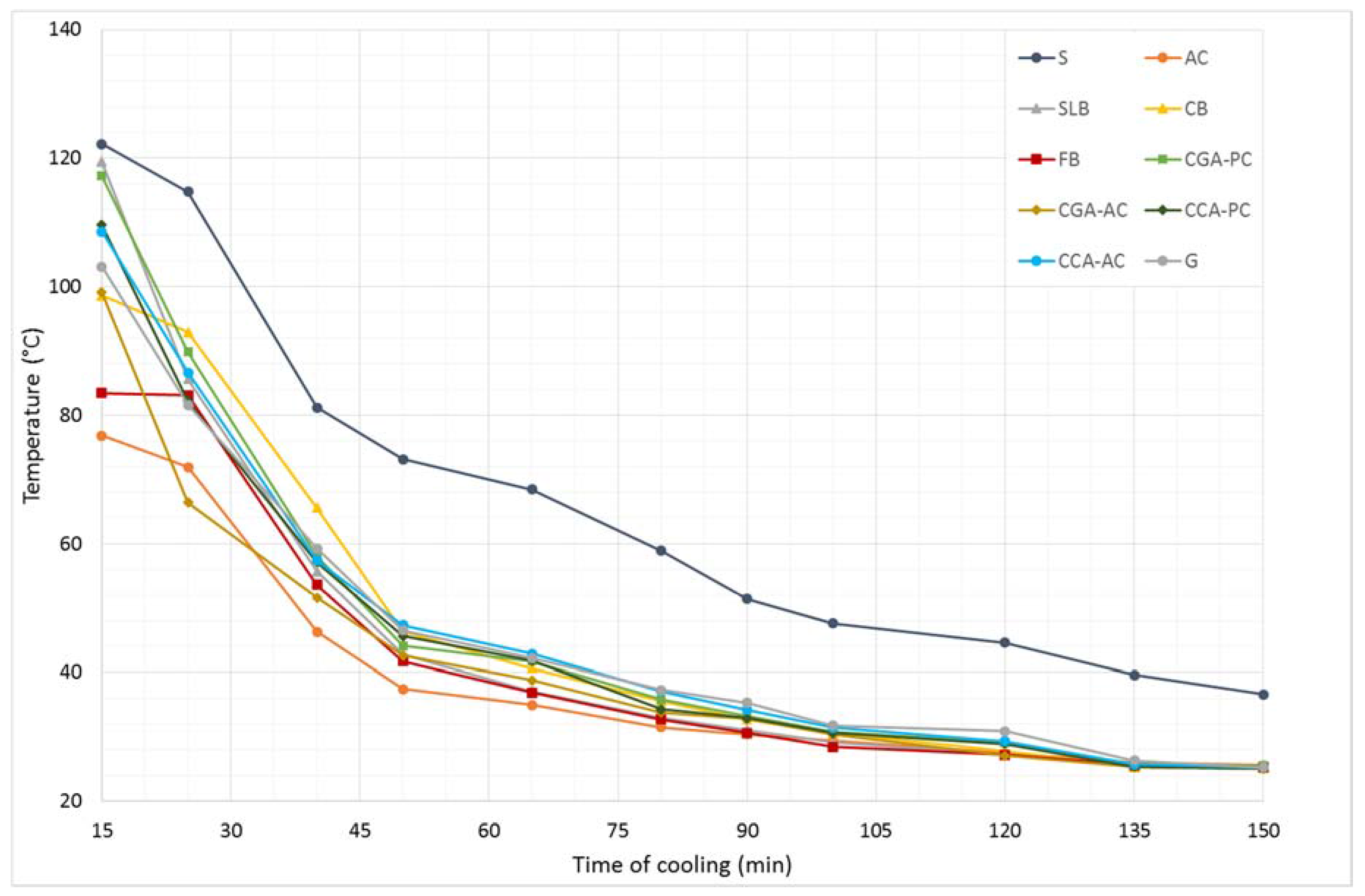
Results from the first stage of the experiment are shown in Figure 4.
In spite of the same size of the samples and the fact that they were left in the same thermal conditions, they showed different thermal characteristics. After the heating process, the specimens had different temperatures. None of the materials, after 3 h of heating did not reach the set temperature. After 15 min of cooling, the highest temperature reached was the steel specimen (122.2 °C), while the lowest was the sample made of the aerated concrete (76.8 °C). The reason for the differences, while heating and cooling of these materials, is their structure and internal interactions between the material’s molecules. Steel is a compact material which has the highest density, and the least amount of voids and free spaces inside its volume in comparison to the other materials tested. In addition, the high thermal conductivity of steel is due to the metallic bonding between molecules. An aerated concrete is radically different in terms of its structure: it has low density and high porosity; the appearance of air voids makes it an insulating material with a low heat transfer coefficient. The porosity of the surface of the aerated concrete gives it the largest contact surface with the cooler room air of all the materials tested. Such an effect unfavorably influences the emission time of the heat stored—the sample very quickly drops in temperature.
The analysis of the temperature drops during further cooling confirms this pattern. The steel sample, despite the fact that after 15 min reached a temperature close to the concrete samples (steel: 122.2 °C; ordinary concrete: 117.2 °C), it remained warm the longest, and the temperature drops in the subsequent intervals were the lowest. The aerated concrete specimen cooled down in the fastest time.
The analysis of the thermal behavior of other samples indicates the superiority of the concretes (including concrete with the ceramic aggregate) over the traditional ceramics in terms of the TES issues. Concrete samples as the more compact material with higher density, heat up at the same time to the higher temperatures under the same conditions (concrete samples: over 100 °C; ceramic samples: less than 100 °C).
The calculation of the thermal power is shown in Table 7. During the analysis of the results, it is noted that the highest thermal power reached was in the steel (8.8 W), and the lowest were concretes (5.3−6.6 W). The lowest thermal power was found in the aerated concrete (1.616 W) and the fireclay brick (2.408 W).
5.2. Stage 2—TES Properties in the Fireplace Operational Conditions
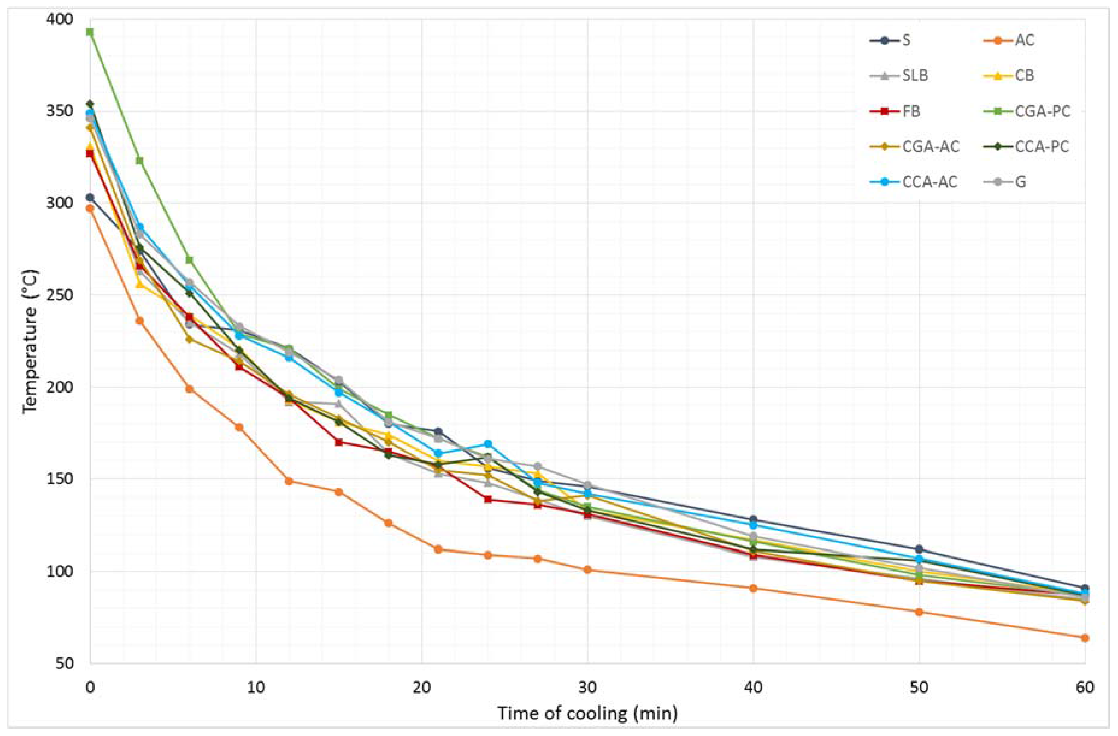
Results from the second stage of the experiment, in which samples were heated up to 400 °C, are shown in Figure 5.
The highest temperature reached was in the CGA-PC specimen (393 °C), while the lowest—similar to the first stage— was the AC sample (297 °C). As the heating temperature increases, the differences in the final temperature of the materials also increases. In this case, the temperature of steel (303 °C), immediately after heating, was only higher from the AC. This shows that the thermal properties of the materials, besides the material’s structure and type of bonding between molecules, also depend on the temperature at which the materials operate.
The temperature drops during cooling showing that aerated concrete cooled down in the shortest time, but a different cooling pattern was observed for the steel sample (in comparison to the first stage). The S sample was characterized by the lowest rate of the temperature drop in a function of the cooling time. After 9 min of cooling the S sample had a higher temperature than all concretes tested and, after 12 min, the S specimen had the highest temperature of all the materials.
The initial temperature after heating of the concretes made with ceramic aggregate was higher than almost all materials, i.e., CCA-PC and CCA-AC, at 354 °C and 349 °C, respectively. Only the CGA-PC sample obtained higher initial temperature, at 393 °C. During the first stage, more materials (S, SLB, and CGA-PC) obtained higher initial temperatures in comparison to the ceramic concretes. The test at 400 °C shows that the TES properties of concretes based on ceramic aggregate are better when the operational temperature increases, compared to other materials.
In the case of the temperature measurement using an infrared camera, when a high-temperature object (interior of the furnace) is reflected, an adulteration of the measurement results may appear unless the ambient temperature is considered. During measurements, the angle of the observation did not exceed 30°, and the emissivity coefficients of the materials’ surface were taken into account.
The analysis of thermal images was carried out using the comparative method. The samples’ temperatures were compared, which were obtained from the thermograms made at one time for the materials. The brightest color on the thermal image during the entire cooling period was observed for the steel sample, which was in agreement with the temperature reading from the thermocouple. The darkest color was recorded for the aerated concrete sample. This fact was consistent with the temperature readings—the AC sample reached the lowest temperature during the heating process, and the temperatures recorded for it in subsequent points in time were also the lowest. The thermographic examination was carried out in order to detect possible anomalies, i.e., an intensified infrared radiation for selected materials, which would not be compatible with temperature readings obtained from the thermocouples. The thermal images of the ceramic materials, concretes, and natural stone were similar in quality. This fact may indicate that concrete composites can fulfill the functions of heat radiators that have traditionally been made in old fireplaces made of ceramic and stone materials.
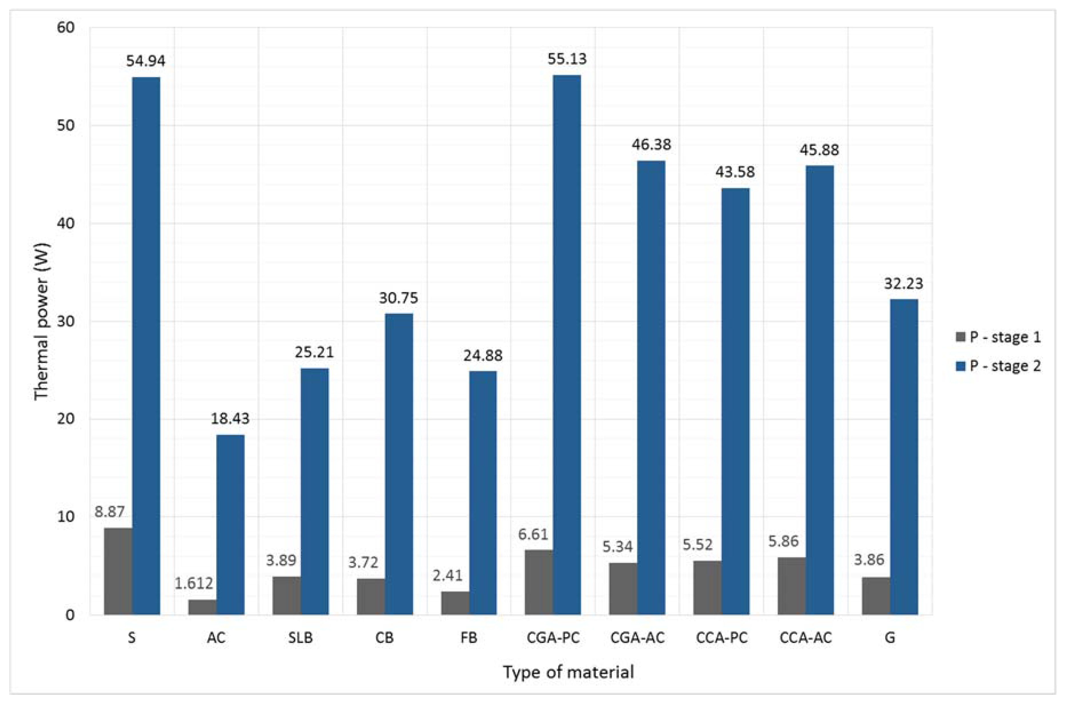
As in the case of the first stage of the experiment, the thermal power of the materials tested was calculated and the results are shown Table 8. The comparison of the thermal power between samples subjected to the low temperature load (stage 1) and the fireplace operational temperature are shown in Figure 6.
The thermal power of the materials heated to 400 °C ranges from 6.2 (for steel) to 11.4 (for aerated concrete) times greater than the materials’ thermal power obtained during the first stage of the experiment. Previously, only the steel obtained higher thermal power than the concrete samples. In the second stage the highest thermal power was achieved by the CGA-PC concrete. All tested concretes had a thermal power greater by an average of 82% than other materials (excluding steel). In addition, the largest increases in the thermal power (between the first and the second stage of the experiment) were achieved in the concretes and the steel sample. This shows that the TES properties of these materials are better when they operate at elevated temperature conditions.
Testing at the operating temperature of the fireplace shows that the concretes (including the fireproof concrete with ceramic waste aggregate) have very good TES properties, and in combination with high durability can successfully be used as a heat accumulator in the construction industry.
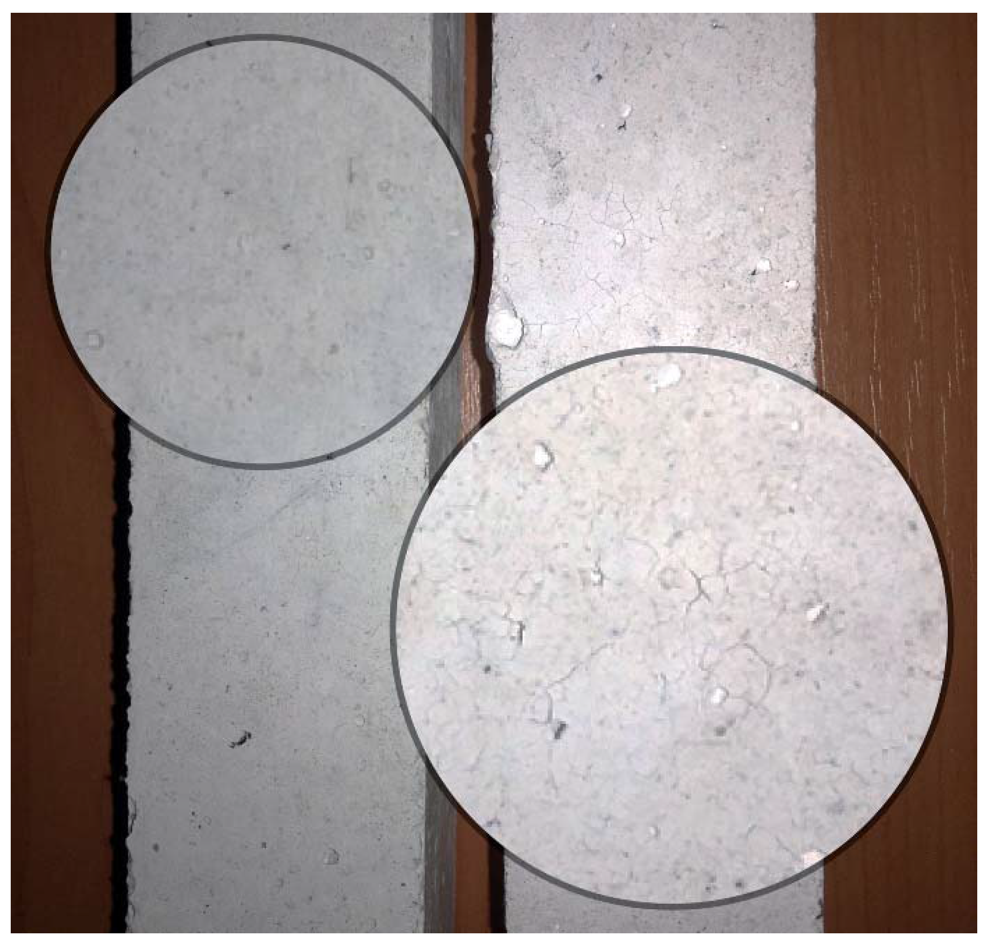
After conducting the research, specimens were left in a laboratory for a period of two weeks, after which their inspection was made. The samples made of concrete with gravel aggregate (CGA-PC, CGA-AC) showed damage in the form of cracks (Figure 7). A similar type of damage was observed for the concrete made of ceramic aggregate and Portland cement (CCA-PC). Damage occurred as a result of too high a temperature during the heating process. Other materials remained intact, including the CCA-AC concrete.
Damage after heating the concretes based on Portland cement (CGA-PC, CCA-PC) made it impossible to determine their basic mechanical properties—the compressive and tensile strength. The edges of the samples flaked off after heating, and the loss of their mass was noted. The concretes based on alumina cement (CGA-AC, CCA-AC) have a compact structure after heating, and it was possible to study their strength characteristics. For CGA-AC, the compressive strength was 28.4 MPa, and the tensile strength was 2.6 MPa. The strength characteristics for CCA-AC were 49.8 MPa and 4.2 MPa, respectively. The conclusion from this observation drew attention to the fact that, among the tested concretes, only the recycled one, for which the ceramic waste aggregate and alumina cement was used (CCA-AC), would be able to work without destruction in the thermal conditions that are present in a fireplace.
6. Conclusions
On the basis of the research obtained from the first and the second stage of the experiment, and the thermal images analysis, general assumptions about the favorable TES parameters of the recycled ceramic concrete were confirmed. Results obtained during the tests have confirmed the beneficial value of the heat stored during the heating, as well as the relatively low temperature drops of concretes while cooling. The tests at higher temperatures were relatively close to those obtained at the lower temperature range. All of the concretes showed good accumulating properties, considerably higher than other compared materials, e.g., red ceramics or fireclay bricks. The tests at higher temperatures, however, have shown that only the heat-resistant concrete (CCA-AC) has appropriate the parameters to work in the operational conditions of a fireplace. Other concretes were characterized by structural damage (mainly cracks) due to the influence of the elevated temperature.
The additional conclusions obtained from the literature study, research, and analysis can be formulated as follows:
- The parameters that determine the possibility of using the material as the TES material are as follows: the heat capacity (the material capacity to absorb and store heat in its volume), and the thermal power (the material ability to return the energy to the environment, in a given time).
- The primary factor determining the TES properties is the maximum temperature to which the material can be heated.
- Concrete made with ceramic waste aggregate and alumina cement, due to the ability to work in temperatures up to 1000 °C, has a high heat accumulation ability. This value is approximately two times higher than that of red ceramics and fireclay bricks. The results of the research also point to the relatively high thermal power of this material.
- The concrete prepared from ceramic waste aggregate is a good heat accumulator. These concretes may, thus, be the starting point for the practical application of such materials to the manufacture of condensing furnaces, or to the interior of fireplaces. Its additional advantage is the ease of forming any shape and the possibility of embedding it in the workplace without previous firing, as is in the case of the ceramics used so far.
Acknowledgments
This work was financially supported by Polish Ministry of Science and Higher Education within the statutory research of cooperating universities: The Main School of Fire Service in Warsaw, Lublin University of Technology, and Collegium Mazovia in Siedlce.
Author Contributions
P.O. and B.Z. conceived the idea of the experiment, conducted the experimental part, and analyzed the results. M.S. translated the article, analyzed the results, and provided manuscript formatting. All authors interpreted and discussed the experimental results. All authors of the article provided substantive comments.
Conflicts of Interest
The authors declare no conflict of interest.
References
- Blaszczynski, T.; Krol, M.; Kaplinski, O.; Paslawski, J.; Zavadskas, E.; Gajzler, M. Usage of green concrete technology in civil engineering. Procedia Eng. 2015, 122, 296–301. [Google Scholar] [CrossRef]
- Motz, H.; Geiseler, J. Products of steel slags an opportunity to save natural resources. Waste Manag. 2001, 21, 285–293. [Google Scholar] [CrossRef]
- Mroueh, U.; Eskola, P.; Laine-Ylijoki, J. Life-cycle impacts of the use of industrial by-products in road and earth construction. Waste Manag. 2001, 21, 271–277. [Google Scholar] [CrossRef]
- Blengini, G.; Garbarino, E. Resources and waste management in turin (italy): The role of recycled aggregates in the sustainable supply mix. J. Clean. Prod. 2010, 18, 1021–1030. [Google Scholar] [CrossRef]
- Knoeri, C.; Binder, C.; Althaus, H. Decisions on recycling: Construction stakeholders’ decisions regarding recycled mineral construction materials. Resour. Conserv. Recycl. 2011, 55, 1039–1050. [Google Scholar] [CrossRef]
- Turk, J.; Mladenovic, A.; Knez, F.; Bras, V.; Sajna, A.; Copar, A.; Slanc, K. Tar-containing reclaimed asphalt—Environmental and cost assessments for two treatment scenarios. J. Clean. Prod. 2014, 81, 201–210. [Google Scholar] [CrossRef]
- Liew, K.M.; Sojobi, A.O.; Zhang, L.W. Green concrete: Prospects and challenges. Constr. Build. Mater. 2017, 156, 1063–1095. [Google Scholar] [CrossRef]
- Tian, H.; Zhang, Y.; Ye, L.; Yang, C. Mechanical behaviours of green hybrid fibre-reinforced cementitious composites. Constr. Build. Mater. 2015, 95, 152–163. [Google Scholar] [CrossRef]
- Anderson, D.; Smith, S.; Au, F. Mechanical properties of concrete utilising waste ceramic as coarse aggregate. Constr. Build. Mater. 2016, 117, 20–28. [Google Scholar] [CrossRef]
- Awoyera, P.O.; Ndambuki, J.M.; Akinmusuru, J.O.; Omole, D.O. Characterization of ceramic waste aggregate concrete. HBRC J. 2016, in press. [Google Scholar] [CrossRef]
- Medina, C.; de Rojas, M.; Frias, M. Properties of recycled ceramic aggregate concretes: Water resistance. Cem. Concr. Compos. 2013, 40, 21–29. [Google Scholar] [CrossRef]
- Senthamarai, R.; Manoharan, P. Concrete with ceramic waste aggregate. Cem. Concr. Compos. 2005, 27, 910–913. [Google Scholar] [CrossRef]
- Halicka, A.; Ogrodnik, P.; Zegardlo, B. Using ceramic sanitary ware waste as concrete aggregate. Constr. Build. Mater. 2013, 48, 295–305. [Google Scholar] [CrossRef]
- Guerra, I.; Vivar, I.; Llamas, B.; Juan, A.; Moran, J. Eco-efficient concretes: The effects of using recycled ceramic material from sanitary installations on the mechanical properties of concrete. Waste Manag. 2009, 29, 643–646. [Google Scholar] [CrossRef] [PubMed]
- Medina, C.; Frias, M.; de Rojas, M. Microstructure and properties of recycled concretes using ceramic sanitary ware industry waste as coarse aggregate. Constr. Build. Mater. 2012, 31, 112–118. [Google Scholar] [CrossRef]
- Medina, C.; de Rojas, M.; Frias, M. Reuse of sanitary ceramic wastes as coarse aggregate in eco-efficient concretes. Cem. Concr. Compos. 2012, 34, 48–54. [Google Scholar] [CrossRef]
- Halicka, A.; Ogrodnik, P.; Zegardło, B. Reuse of ceramic sanitary waste as an aggregate in concrete resistant to high temperature. Budownictwo i Architektura 2013, 12, 153–160. (In Polish) [Google Scholar]
- Halicka, A.; Zegardło, B. Sanitary ceramic waste as a concrete aggregate. Przegląd Budowlany 2011, 82, 50–55. (In Polish) [Google Scholar]
- Subasi, S.; Ozturk, H.; Emiroglu, M. Utilizing of waste ceramic powders as filler material in self-consolidating concrete. Constr. Build. Mater. 2017, 149, 567–574. [Google Scholar] [CrossRef]
- Kannan, D.; Aboubakr, S.; El-Dieb, A.; Taha, M. High performance concrete incorporating ceramic waste powder as large partial replacement of portland cement. Constr. Build. Mater. 2017, 144, 35–41. [Google Scholar] [CrossRef]
- Pokorny, J.; Fort, J.; Pavlikova, M.; Studnicka, J.; Pavlik, Z.; Reiterman, P. Application of mixed ceramic powder in cement based composites. Adv. Mater. Res. 2014, 1054, 177–181. [Google Scholar] [CrossRef]
- Vejmelkova, E.; Konakova, D.; Kulovana, T.; Hubacek, A.; Cerny, R.; Reiterman, P. Mechanical and thermal properties of moderate-strength concrete with ceramic powder used as supplementary cementitious material. Adv. Mater. Res. 2014, 1054, 194–198. [Google Scholar] [CrossRef]
- Ogrodnik, P.; Zegardło, B.; Halicka, A. Preliminary assessment of utilization of sanitary ceramics wastes as an aggregate in concrete working at the high temperature. Bezpieczeństwo i Technika Pożarnicza 2012, 25, 49–56. (In Polish) [Google Scholar]
- Ogrodnik, P.; Zegardło, B.; Radzikowska, M. Use of post-production sanitary ceramic waste as a filler in cement composites of high chemical resistance. Przemysł Chemiczny 2017, 96, 1100–1104. [Google Scholar]
- Zegardło, B.; Halicka, A. Analysis of thermal properties of concrete made using aggregate from sanitary ceramic wastes. Budownictwo i Architektura 2011, 9, 39–49. (In Polish) [Google Scholar]
- Ogrodnik, P.; Szulej, J. The impact of aeration of concrete based on ceramic aggregate, exposed to high temperatures, on its strength parameters. Constr. Build. Mater. 2017, 157, 909–916. [Google Scholar] [CrossRef]
- Zegardlo, B.; Szelag, M.; Ogrodnik, P. Ultra-high strength concrete made with recycled aggregate from sanitary ceramic wastes—The method of production and the interfacial transition zone. Constr. Build. Mater. 2016, 122, 736–742. [Google Scholar] [CrossRef]
- Cachim, P. Mechanical properties of brick aggregate concrete. Constr. Build. Mater. 2009, 23, 1292–1297. [Google Scholar] [CrossRef]
- Correia, J.; de Brito, J.; Pereira, A. Effects on concrete durability of using recycled ceramic aggregates. Mater. Struct. 2006, 39, 169–177. [Google Scholar] [CrossRef]
- Debieb, F.; Kenai, S. The use of coarse and fine crushed bricks as aggregate in concrete. Constr. Build. Mater. 2008, 22, 886–893. [Google Scholar] [CrossRef]
- Pacheco-Torgal, F.; Jalali, S. Reusing ceramic wastes in concrete. Constr. Build. Mater. 2010, 24, 832–838. [Google Scholar] [CrossRef]
- Pan, J.; Zou, R.; Jin, F. Experimental study on specific heat of concrete at high temperatures and its influence on thermal energy storage. Energies 2017, 10, 33. [Google Scholar] [CrossRef]
- Wu, C.; Pan, J.; Zhong, W.; Jin, F. Testing of high thermal cycling stability of low strength concrete as a thermal energy storage material. Appl. Sci.-Basel 2016, 6, 271. [Google Scholar] [CrossRef]
- Bravo, M.; de Brito, J.; Evangelista, L. Thermal performance of concrete with recycled aggregates from CDW plants. Appl. Sci.-Basel 2017, 7, 740. [Google Scholar] [CrossRef]
- Dong, Z.; Li, Z.; Zhou, H.; Wu, K. Development of thermal energy storage concrete. Cem. Concr. Res. 2004, 34, 927–934. [Google Scholar]
- Ling, T.; Poon, C. Use of phase change materials for thermal energy storage in concrete: An overview. Constr. Build. Mater. 2013, 46, 55–62. [Google Scholar] [CrossRef]
- Gracia, A.; Cabeza, L.F. Phase change materials and thermal energy storage for buildings. Energy Build. 2015, 103, 414–419. [Google Scholar] [CrossRef]
- Kalinowski, E. Thermodynamics; Wydawnictwo Politechniki Wrocławskiej: Wrocław, Poland, 1994. (In Polish) [Google Scholar]
- Kucharczyk, W.; Mazurkiewicz, A.; Wojciech, L. Modern Construction Materials—Selected Issues; Politechnika Radomska: Radom, Poland, 2010. (In Polish) [Google Scholar]
- Pelay, U.; Lu, L.; Fan, Y.; Stitou, D.; Rood, M. Thermal energy storage systems for concentrated solar power plants. Renew. Sustain. Energy Rev. 2017, 79, 82–100. [Google Scholar] [CrossRef]
- Zhang, H.; Kong, W.; Tan, T.; Baeyens, J. High-efficiency concentrated solar power plants need appropriate materials for high-temperature heat capture, conveying and storage. Energy 2017, 139, 52–64. [Google Scholar] [CrossRef]
- Tiskatine, R.; Aharoune, A.; Bouirden, L.; Ihlal, A. Identification of suitable storage materials for solar thermal power plant using selection methodology. Appl. Therm. Eng. 2017, 117, 591–608. [Google Scholar] [CrossRef]
- Jemmal, Y.; Zari, N.; Maaroufi, M. Experimental characterization of siliceous rocks to be used as filler materials for air-rock packed beds thermal energy storage systems in concentrated solar power plants. Sol. Energy Mater. Sol. Cells 2017, 171, 33–42. [Google Scholar] [CrossRef]
- Khare, S.; Dell’Amico, M.; Knight, C.; McGarry, S. Selection of materials for high temperature sensible energy storage. Sol. Energy Mater. Sol. Cells 2013, 115, 114–122. [Google Scholar] [CrossRef]
- Jamroży, Z. Concrete and Ist Technologies; Wydawnictwo Naukowe PWN: Warszawa, Poland, 2008. (In Polish) [Google Scholar]
Figure 1.
The samples used for testing: (a) in a laboratory dryer; and (b) on the temperature measurement stand.
Figure 1.
The samples used for testing: (a) in a laboratory dryer; and (b) on the temperature measurement stand.

Figure 2.
The furnace used in the study: (a) scheme; and (b) real image.

Figure 3.
Thermal images of materials tested after 3 min of cooling.

Figure 4.
A temperature drop of the materials during cooling on the first stage of the experiment; S: steel; AC: aerated concrete; SLB: sand-lime brick; CB: ceramic brick; FB: fireclay brick; CGA-PC: concrete with gravel aggregate and Portland cement; CGA-AC: concrete with gravel aggregate and alumina cement; CCA-PC: concrete with ceramic aggregate and Portland cement; CCA-AC: concrete with ceramic aggregate and alumina cement; G: granite.

Figure 5.
The relation of the temperature drop as a function of the cooling time during the second stage of the experiment; designations are the same as for Figure 4.
Figure 5.
The relation of the temperature drop as a function of the cooling time during the second stage of the experiment; designations are the same as for Figure 4.

Figure 6.
Comparison of the materials’ thermal power between the results obtained in the course of the first and the second stages of the experiment.
Figure 6.
Comparison of the materials’ thermal power between the results obtained in the course of the first and the second stages of the experiment.

Figure 7.
Surface of CCA-AC (left) and CGA-AC (right) samples after heating at 400 °C.


| No. | Material | Specific Heat (J/(kg∙K)) | Bulk Density (kg/m3) | Heat Capacity (MJ/(m3·K)) |
|---|---|---|---|---|
| 1 | Benzene | 17,200 | 880 | 15.136 |
| 2 | Water | 4190 | 998 | 4.181 |
| 3 | Ice | 2100 | 880 | 1.848 |
| 4 | Gasoline | 2100 | 700 | 1.470 |
| 5 | Air | 1005 | 1.29 | 0.001 |
| 6 | iron | 449 | 7875 | 3.535 |
| 7 | Copper | 385 | 8933 | 3.439 |
| 8 | Brass | 377 | 8400 | 3.166 |
| 9 | Zinc | 389 | 7130 | 2.773 |
| 10 | Aluminum | 902 | 2720 | 2.453 |
| 11 | Concrete | 1130 | 2450 | 2.769 |
| 12 | Granite | 670 | 2670 | 1.788 |
| 13 | Brick | 850 | 1400 | 1.190 |
| 14 | River sand | 800 | 1550 | 1.240 |
| 15 | Ceramics | 880 | 2640 | 2.323 |
| 16 | Terracotta | 920 | 2000 | 1.840 |
| 17 | Glass | 840 | 2500 | 2.100 |
| 18 | Styrofoam | 1200 | 20 | 0.024 |
Table 2.
The maximum amount of the thermal energy, which can be stored in a unit volume of the material.
Table 2.
The maximum amount of the thermal energy, which can be stored in a unit volume of the material.
| No. | Material | Heat Capacity (MJ/(m3·K)) | Initial Temperature (°C) | Maximum Temperature (°C) | Temperature Difference (°C) | Heat Accumulation Capacity (MJ/m3) |
|---|---|---|---|---|---|---|
| 1 | Water | 4.181 | 20 | 100 | 80 | 334.5 |
| 2 | Steel | 3.535 | 20 | 1600 | 1580 | 5586.7 |
| 3 | Styrofoam | 0.024 | 20 | 80 | 60 | 1.4 |
| 4 | Granite | 1.789 | 20 | 900 | 880 | 1574.2 |
| 5 | Common brick | 1.190 | 20 | 380 | 360 | 428.4 |
| 6 | Fireclay brick | 1.190 | 20 | 1400 | 1380 | 1642.2 |
| 7 | Ordinary concrete | 2.769 | 20 | 250 | 230 | 636.7 |
| 8 | Heat-resistant concrete | 2.769 | 20 | 1000 | 980 | 3266.8 |
Table 3.
Basic properties of aggregates used in the study—gravel and ceramic.
| Property | Unit | Type of Aggregate | |
|---|---|---|---|
| Gravel | Sanitary Ceramics | ||
| Specific density | g/cm3 | 2.65 | 2.64 |
| Bulk density | g/cm3 | 2.46 | 2.36 |
| Compressive strength | MPa | 200 | 400–600 |
| Modulus of elasticity | GPa | 43 | 40–70 |
| Degree of crushing | - | 6.8 | 8.9 |
| Water absorption | % | 0.6 | 1.53 |
Table 4.
Basic properties of the cements used to manufacture the tested concretes.
| Property | Type of Cement | ||
|---|---|---|---|
| Unit | High Alumina Górkal 70 | CEM I 42,5N—SR 3/NA | |
| Blaine specific surface area | cm2/g | 4000–5000 | 3688 |
| Beginning of the binding time | min | ≥75 | 233 |
| End of the binding time | min | <240 | 291 |
| Compressive strength after 6 h | MPa | >18 | - |
| Compressive strength after 24 h | MPa | >30 | - |
| Compressive strength after 2 days | MPa | - | 23.9 |
| Compressive strength after 28 days | MPa | - | 55.9 |
| Specific density | g/cm3 | 2.96 | 3.01 |
| Cl content | % | ≤0.10 | 0.07 |
| SO3 content | % | ≤0.50 | 2.77 |
Table 5.
The concretes’ mix proportions.
| Component | Amount (kg/m3) |
|---|---|
| Alumina/Portland cement | 493.38 |
| Fine aggregate 0–4 mm | 991.37 |
| Coarse aggregate 4–8 mm | 396.55 |
| Water | 201.38 |
Table 6.
Basic features of the concretes used in the study.
| Feature | Unit | Concrete Type | Test Method | |||
|---|---|---|---|---|---|---|
| CGA-PC | CGA-AC | CCA-PC | CCA-AC | |||
| Bulk density | kg/m3 | 2269 (0.36) | 2238 (0.22) | 2178 (0.32) | 2165 (0.28) | EN 12390-7 |
| Water absorption | % | 3.24 (2.35) | 3.11 (1.70) | 3.79 (2.21) | 3.98 (2.46) | According to [45] |
| Open porosity | % | 7.35 (2.12) | 6.96 (1.63) | 8.25 (2.08) | 8.62 (3.11) | According to [45] |
| Compressive strength | MPa | 49.9 (1.61) | 56.4 (1.49) | 74.5 (2.46) | 88.6 (4.50) | EN 12390-3 |
Coefficient of variation in brackets. CGA-PC: concrete with gravel aggregate and Portland cement; CGA-AC: concrete with gravel aggregate and alumina cement; CCA-PC: concrete with ceramic aggregate and Portland cement; CCA-AC: concrete with ceramic aggregate and alumina cement.
Table 7.
The thermal power of the materials tested—the first stage of the experiment.
| Material Type | S | AC | SLB | CB | FB | CGA-PC | CGA-AC | CCA-PC | CCA-AC | G |
|---|---|---|---|---|---|---|---|---|---|---|
| m (kg) | 2.078 | 0.252 | 0.465 | 0.536 | 0.439 | 0.574 | 0.575 | 0.520 | 0.560 | 0.666 |
| c (J/(kg∙K)) | 449 | 1130 | 800 | 850 | 850 | 1130 | 1130 | 1130 | 1130 | 670 |
| ΔT (K) | 85.6 | 51.2 | 94.1 | 73.5 | 58.1 | 91.7 | 74.0 | 84.5 | 83.4 | 77.9 |
| ΔQ (kJ) | 79.87 | 14.55 | 35.01 | 33.49 | 21.68 | 59.48 | 48.04 | 49.65 | 52.77 | 34.73 |
| t (s) | 9000 | 9000 | 9000 | 9000 | 9000 | 9000 | 9000 | 9000 | 9000 | 9000 |
| P (W) | 8.874 | 1.616 | 3.889 | 3.720 | 2.408 | 6.608 | 5.337 | 5.516 | 5.863 | 3.859 |
where: m: sample weight; c: specific heat; ΔT: temperature difference; ΔQ: amount of emitted energy; t: emission time; P: thermal power; S: steel; AC: aerated concrete; SLB: sand-lime brick; CB: ceramic brick; FB: fireclay brick; G: granite.
Table 8.
The thermal power of materials tested—second stage of the experiment.
| Material Type | S | AC | SLB | CB | FB | CGA-PC | CGA-AC | CCA-PC | CCA-AC | G |
|---|---|---|---|---|---|---|---|---|---|---|
| m (kg) | 2.078 | 0.252 | 0.465 | 0.536 | 0.439 | 0.574 | 0.575 | 0.52 | 0.56 | 0.666 |
| c (J/(kg∙K)) | 449 | 1130 | 800 | 850 | 850 | 1130 | 1130 | 1130 | 1130 | 670 |
| ΔT (K) | 212 | 233 | 244 | 243 | 240 | 306 | 257 | 267 | 261 | 260 |
| ΔQ (kJ) | 197.8 | 66.3 | 90.8 | 110.7 | 89.6 | 198.5 | 167.0 | 156.9 | 165.2 | 116.0 |
| t (s) | 3600 | 3600 | 3600 | 3600 | 3600 | 3600 | 3600 | 3600 | 3600 | 3600 |
| P (W) | 54.94 | 18.43 | 25.21 | 30.75 | 24.88 | 55.13 | 46.38 | 43.58 | 45.88 | 32.23 |
where: m: sample weight, c: specific heat, ΔT: temperature difference, E = ΔQ = c∙m∙ΔT: amount of emitted energy, t: emission time, P: thermal power.
© 2017 by the authors. Licensee MDPI, Basel, Switzerland. This article is an open access article distributed under the terms and conditions of the Creative Commons Attribution (CC BY) license (http://creativecommons.org/licenses/by/4.0/).
Share and Cite
MDPI and ACS Style
Ogrodnik, P.; Zegardło, B.; Szeląg, M. The Use of Heat-Resistant Concrete Made with Ceramic Sanitary Ware Waste for a Thermal Energy Storage. Appl. Sci. 2017, 7, 1303. https://0-doi-org.brum.beds.ac.uk/10.3390/app7121303
AMA Style
Ogrodnik P, Zegardło B, Szeląg M. The Use of Heat-Resistant Concrete Made with Ceramic Sanitary Ware Waste for a Thermal Energy Storage. Applied Sciences. 2017; 7(12):1303. https://0-doi-org.brum.beds.ac.uk/10.3390/app7121303
Chicago/Turabian StyleOgrodnik, Paweł, Bartosz Zegardło, and Maciej Szeląg. 2017. "The Use of Heat-Resistant Concrete Made with Ceramic Sanitary Ware Waste for a Thermal Energy Storage" Applied Sciences 7, no. 12: 1303. https://0-doi-org.brum.beds.ac.uk/10.3390/app7121303
Note that from the first issue of 2016, this journal uses article numbers instead of page numbers. See further details here.