Cognitive Routing in Software-Defined Underwater Acoustic Networks


School of Electrical Engineering, University of Ulsan (UOU), Ulsan 680-749, Korea
*
Author to whom correspondence should be addressed.
Appl. Sci. 2017, 7(12), 1312; https://0-doi-org.brum.beds.ac.uk/10.3390/app7121312
Submission received: 17 November 2017
/
Revised: 13 December 2017
/
Accepted: 13 December 2017
/
Published: 17 December 2017
(This article belongs to the Special Issue Underwater Acoustics, Communications and Information Processing)
Abstract
:There are two different types of primary users (natural acoustic and artificial acoustic), and there is a long propagation delay for acoustic links in underwater cognitive acoustic networks (UCANs). Thus, the selection of a stable route is one of the key design factors for improving overall network stability, thereby reducing end-to-end delay. Software-defined networking (SDN) is a novel approach that improves network intelligence. To this end, we propose a novel SDN-based routing protocol for UCANs in order to find a stable route between source and destination. A main controller is placed in a surface buoy that is responsible for the global view of the network, whereas local controllers are placed in different autonomous underwater vehicles (AUVs) that are responsible for a localized view of the network. The AUVs have fixed trajectories, and sensor nodes within transmission range of the AUVs serve as gateways to relay the gathered information to the controllers. This is an SDN-based underwater communications scheme whereby two nodes can only communicate when they have a consensus about a common idle channel. To evaluate our proposed scheme, we perform extensive simulations and improve network performance in terms of end-to-end delay, delivery ratio, and overhead.
1. Introduction
The underwater acoustic network (UAN) is a form of advanced technology that allows the communication among different acoustic users to deal with various applications that cover ranges from the depths of the ocean to its surface. Underwater communications systems have gained much attention due to increased demand by offshore industries for these applications. The communications systems include both natural acoustic systems (e.g., marine mammals) and artificial acoustic systems (e.g., sonar systems). Due to the high attenuation of radio/optical waves in water, the only reliable medium for communications in the ocean is acoustic waves [1]. Therefore, both natural and artificial acoustic systems rely on acoustic waves for communications. Moreover, the unique challenges of the underwater environment (e.g., severe path loss, limited bandwidth, long propagation delay) make it highly complicated for these networks to establish a stable route with an efficient routing scheme. In addition, among the unique challenges in the underwater environment, spectrum scarcity is a critical issue in this research area, and this needs to be addressed for safe and stable communications.
Due to the limited spectrum (between 1 and 40 KHz [2]), various acoustic users trigger high competition to utilize the spectrum resources efficiently. Therefore, safe and stable communications have become a great challenge in the underwater environment. To address these issues, a new technique is required that simultaneously considers spectrum sensing and routing for underwater networks. Cognitive acoustics (CA) was announced as a viable solution to resolve spectrum scarcity issues in underwater networks [3] because it can utilize the spectrum in an environmentally friendly manner (i.e., avoiding harmful interference with natural acoustic systems) and in an efficient manner (i.e., providing high spectrum utilization). For this purpose, a sensing technique is required to detect the presence/absence of the primary user (PU), thereby ensuring that PU activity is safeguarded. An acoustic link is only formed when two acoustic users reach a consensus about a common idle channel.
Several routing protocols have been proposed for underwater networks, but for cognitive underwater networks, the number of protocols that consider a cognitive capability with a routing technique is limited. Nevertheless, safe and stable communications issues for underwater cognitive acoustic networks (UCANs) are still under investigation in order to reach a robust and distinguished solution. Moreover, existing underwater networks are composed of thousands of nodes that are deployed to collect data in an area of interest in the ocean, thereby satisfying the requirements of a single application. Another issue in these networks is that due to application constraints and vendor dependency, it is difficult to use these nodes for other services in the same area [4]. To overcome the shortcomings with existing architectures in underwater networks, we intend to apply a new concept of software-defined networking (SDN) in this domain. SDN is an emerging technology that increases network intelligence by separating the control plane from the data plane [5]. SDN technology has been progressively diffused into different types of network systems, including UANs, in order to overcome the limitations in these networks [1,4,6]. It offers the flexibility to adapt and satisfy different applications.
Our main objective is to combine a cognitive capability with a routing technique in underwater networks by using the SDN approach. We intend to overcome the problems of spectrum scarcity and high latency in UCANs. Our goal is to select the best route between source and destination that maximizes the capacity and minimizes the duration among all the paths. Spectrum sensing is done with an orthogonal frequency division multiplexing (OFDM)-based energy detection scheme. The SDN controllers programmatically configure the traffic and have a global view of the network. Our proposed scheme has a single main controller (MC) and several local controllers (LCs). LCs are mobile autonomous underwater vehicles (AUVs) that have a localized view of the network. Sensor nodes send requests to LCs querying them for a route to the target node. The LC quickly responds to the request if it has a route to the destination; otherwise, it forwards the request to the MC.
The key contributions of this paper are as follows:
- i
- A novel technique, the cognitive acoustic software-defined underwater network (CA-SDUN), which ensures cognitive routing in underwater sensor networks based on a new concept for SDN, is proposed in order to find a stable route between source and destination. AUVs moving in fixed trajectories serve as local controllers. In this manner, the technique improves the spectrum opportunities and network stability for different users communicating with each other in the ocean.
- ii
- The SDN is applied for the first time using a combination of a cognitive capability and a routing technique in order to overcome the problems of limited services altogether due to application constraints, spectrum scarcity, and high latency.
2. Related Work
Routing in UCANs is challenging as compared to conventional routing protocols in UANs. Yan et al. [7] proposed depth-based routing (DBR) for underwater sensor networks to provide scalable and efficient services for dense networks. DBR is based on a greedy algorithm in which each sensor node makes a decision by comparing its own depth with the depth of the previous node. The protocol achieved a 95% packet delivery ratio without considering recovery algorithms to bypass the connectivity voids. Pressure routing for underwater sensor networks [8] addressed the local maxima by maintaining a recovery route. In this algorithm, a route discovery method was provided that implements hop-limited two-dimensional (2D) flooding. To select a set of forwarding nodes that maximizes greedy progress and limits co-channel interference, an opportunistic routing mechanism and a dead-end recovery method were used. To bypass connectivity voids in a network, Noh et al. [9] proposed void-aware pressure routing (VAPR), a modified version of pressure routing, to ensure loop freedom for mobile networks. VAPR is a soft-state protocol that uses enhanced beaconing to propagate the data from sonobuoys to sensor nodes, and opportunistic directional data forwarding then builds a directional trail to the closest sonobuoy.
Pompili et al. [10] proposed two distributed geographic routing algorithms for delay-insensitive and delay-sensitive applications in underwater environments to investigate the problem of data gathering. They achieved high acoustic channel efficiency by limiting the error rate for each packet. The objective of these protocols was to minimize energy consumption by jointly selecting the best next hop, the optimal transmit power, and the best forward error correction (FEC) rate. The channel-aware routing protocol (CARP) [11] is another robust relay-selection mechanism to achieve high-throughput efficiency. The protocol exploits link quality information to route around connectivity voids and shadow zones. Yoon et al. [12] proposed an AUV-aided underwater routing protocol (AURP) to maximize the data delivery ratio and minimize the energy consumption of underwater sensor nodes. The scheme not only uses heterogeneous acoustic channels but also controls the mobility of the AUVs. This was the first protocol to employ multiple AUVs as relay nodes in a multi-hop underwater acoustic sensor network. Carlson et al. [13] designed a reactive, link-state mobile ad hoc network routing protocol—a form of location-aware source routing (LASR) that considers the characteristics of underwater acoustic networks. LASR uses the idea of dynamic source routing (DSR) for communications between AUVs. The protocol achieved greater reliability than both DSR and blind-flooding routing protocols.
The diagonal and vertical routing protocol (DVRP) [14] is another method proposed for underwater wireless sensor networks to improve throughput and to reduce network load by calculating a flooding zone. The protocol increases the reliability of the network by preventing flooding in the whole network. Coutinho et al. [15] proposed a geographic and opportunistic routing protocol with depth adjustment-based topology control for communication recovery (abbreviated as GEDAR) to improve the data packet delivery ratio in mobile underwater sensor networks. The protocol uses greedy opportunistic forwarding to route packets and to move void nodes to new depths in order to adjust the topology. Ilyas et al. [16] proposed an AUV-aided efficient data-gathering (AEDG) routing protocol for reliable data delivery in underwater sensor networks. AEDG employs an AUV for data collection from gateways; to associate sensor nodes with gateways, it uses a shortest path tree (SPT) algorithm. The protocol achieved better performance in terms of data gathering and energy consumption, even in harsh oceanic conditions. Rani and Talwar [17] proposed an energy-efficient chain-based routing protocol for data gathering in underwater sensor networks. The whole network topology is divided into subregions where a cluster head in each sub region is responsible for gathering and transmission of data to the next upper region. AUV-aided routing method integrated path planning (AA-RP) [18] integrated the AUV’s dynamic path planning algorithms into the routing protocol. It utilized the cooperation of sensor nodes to reduce energy consumption by selecting gateway nodes (GNs) as agents of AUVs, which communicate with the AUVs when ordinary sensor nodes fail to make connections. The AUVs are mobile sink nodes that forward data from sensor nodes to the surface of the ocean.
None of these routing protocols for underwater sensor networks considered spectrum scarcity issues caused by limited communications frequencies. Proposing a cognitive routing protocol that takes the spectrum scarcity issue into account is essential in order to meet the increasing demands of underwater acoustic users. Luo et al. [19] proposed a novel medium access control (MAC) protocol, called dynamic control channel MAC (DCC-MAC), by investigating the congestion of control channel in a UCAN. The important feature of this protocol is that each node could adjust and extend the bandwidth of its control channel by flexibly selecting proper data channels. A receiver-initiated spectrum management (RISM) [20] system is another protocol proposed for UCANs. It allows acoustic users to efficiently and courteously utilize the spectrum with both natural acoustic systems and artificial acoustic systems. The system increases the overall data transmission rate by combining a collision avoidance mechanism with joint power and channel allocation. Its results showed better performance for both the tree topology and the partially connected mesh topology by integrating spectrum sensing at the physical layer with spectrum sharing at the medium access control layer. Li et al. [21] proposed a cognitive acoustic transmission scheme, called dolphin-aware data transmission (DAD-Tx) to achieve the optimal end-to-end throughput with dolphin awareness. The protocol achieved better performance by modeling the dolphins’ activities and mathematically describing the dolphin-awareness as a probabilistic constraint. OFDM-based spectrum-aware routing (OSAR) [22] was proposed to combine cognitive capability with a routing technique in order to overcome the problems of spectrum scarcity and high latency in underwater cognitive networks.
Similarly, research in software-defined underwater networks is still very limited. SoftWater [23] was first introduced to facilitate such developments and to support a variety of applications for next-generation underwater sensor networks. With separation of the control and data planes, SoftWater provides a hardware infrastructure, software networking algorithms, heterogeneous underwater communications technologies, fault recovery schemes, and underwater mobility management. A software-defined network-based solution [4] was proposed to build an architecture for underwater networks in big data, which includes design of both the data plane and control plane. The study was supposed to maximize capacity, reduce management complexity, and provide technical support for underwater acoustic sensor networks. A new high data rate software-defined underwater acoustic networking platform, SEANet G2 (second generation) [24], was proposed to provide several benefits over existing underwater acoustic platforms. The study was designed to describe the hardware, software, and network architecture of the proposed platform. The design demonstrates data rates of 522 kbit/s achieved at sea over short horizontal links. Lal et al. [25] discussed and reviewed the state-of-the-art security threats for underwater networks along with their existing solutions. The study addressed main research challenges related to the cooperation of static and mobile nodes and presented future solutions based on software-defined cognitive networking with the support for cross-layering communications and context-aware networking. Consequently, combining cognitive principles with routing schemes to design an algorithm for cognitive acoustic software-defined underwater networks has not yet been considered. This is the first work implementing a cognitive routing protocol in an SDUN that simultaneously considers spectrum sensing and routing for underwater communications. A comparison of all schemes described in this section is given in Table 1.
3. Proposed Cognitive Acoustic Software-Defined Underwater Network
We propose a cognitive routing protocol for software-defined underwater acoustic networks. The objective of this novel routing protocol is to overcome major issues in existing underwater communications that lead to network deterioration. This work combines a cognitive capability with a routing technique in underwater networks by using SDN as a new candidate to improve network performance and communications reliability. Taking advantage of SDN, we propose that the sensor nodes within the considered network be used for various services in the same area. This means that the sensor nodes working for one application collect information from their surroundings and send the gathered data to the controller. This logically centralized controller then performs data scheduling and network management to collect information of interest for any other application in order to take full advantage of the whole network. Our aim is to find a stable route between source and destination by jointly selecting the channel and relay node in an efficient and reliable manner.
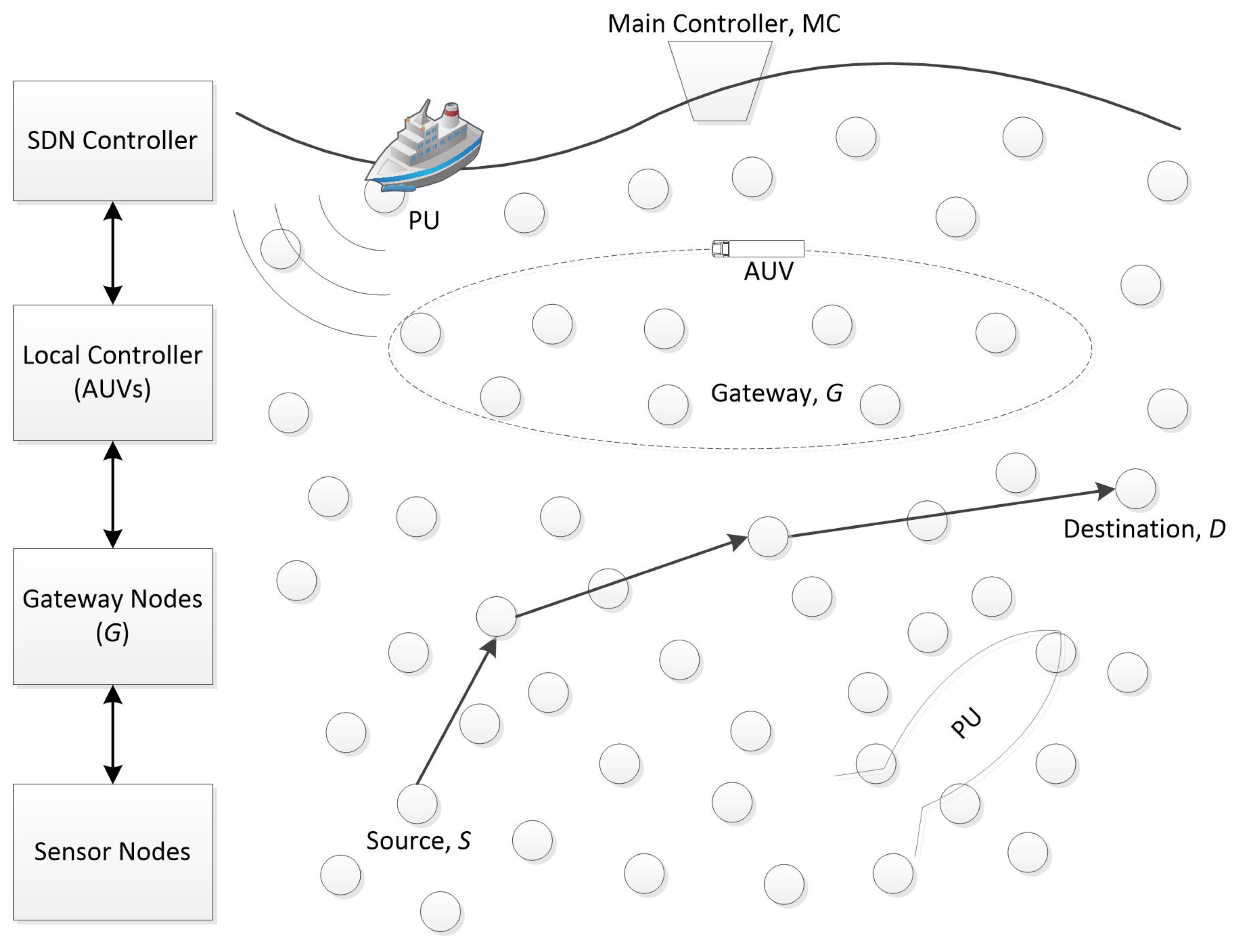
A cognitive acoustic software-defined underwater network is shown in Figure 1, where a source node in the deep ocean is looking for a stable route to a destination far away from it at a different depth in the ocean. The CA-SDUN considers C different communicating nodes. A surface buoy serving as a main controller keeps global updated information on the network. The mobile AUVs (i.e., LCs) improve network reliability by sharing the burden of the single main controller. LCs move on fixed trajectories where the track is maintained by the MC. The sensor nodes, G, within transmission range of the LCs’ track, serve as gateways between conventional sensor nodes, N, and the AUVs, and send information to all neighboring nodes as an extended beacon message. The nodes receiving the messages keep a record of these gateways in their flow tables. This is a four-layered hierarchical network scheme where the first two layers (MC and LCs) communicate directly with each other while gateways (the third layer) are used between sensor nodes (the fourth layer) and the AUVs, as shown in Figure 1. These gateways collect data from all neighboring nodes and store this information until passing it over to the LCs. The double-layering of controllers (MC and LCs) improves network performance in terms of delay and overhead. Both natural acoustic systems (e.g., marine mammals) and artificial acoustic systems (e.g., sonar systems) play the role of primary users (PUs), as shown in Figure 1. All sensor nodes periodically update their current network state with each other and send the gathered information to LCs (either directly or via gateways). All LCs share their localized view of the network with the MC, such that the MC establishes a global network view.
The protocol has two phases: beaconing and route estimation. The beaconing phase establishes the global and localized network states for the MC and LCs, respectively, and updates all the sensor nodes with the current network state. In the route estimation phase, a querying node sends a route request message to an LC. On receiving the message, the LC checks its flow table to determine if it has an updated route to the destination. It quickly responds to the source node without contacting the MC if it finds the updated route in its flow table. In the following subsections, we will discuss each phase in depth.
- Beaconing Phase: In the beaconing phase, all sensor nodes (either gateways or conventional nodes) send a beacon message to their neighbors. The beacon message includes node ID, depth, channel state, and speed. Channel state is the presence or absence of the primary user (PU), which will be explained in the next subsection. The MC sends a request message to the LCs in order to maintain the global network state. Each LC forwards this message to all the nodes within transmission range. By doing so, gateway nodes exchange the gathered data with the LCs, which forward it to the MC. The gateway nodes identify themselves as a gateway (an extra entity) in the beacon message. At the conclusion of this phase, all the communicating nodes in the network are aware of the updated network state. In this way, any querying node, whenever it comes across link fragility, can ask the controller for an updated stable route to a destination without sending the packet back to the source node.
- Route Estimation Phase: When a source node wants to communicate with the destination node, it sends a request message to the controller. The foremost part of this cognitive routing scheme that makes it efficient is the estimation of path duration between source and destination. This is a challenging task for any source node in an underwater environment when one kind of PU includes marine mammals. To make it possible, we apply the SDN technique so that the controllers are responsible for providing the best stable route between source and destination by jointly selecting both channel and relay. We all know that the unpredicted movement of marine mammals makes the underwater environment more challenging, which results in several fragile links. For that reason, the two layers of controllers help the sensor nodes with the provision of stable links by keeping an updated network state. There are two possibilities for the source node: either it is outside the transmission range of an LC, or it is within transmission range of an LC.Case 1: Source outside transmission rangeThe source node needs to find the best relay node to reach any gateway when it is outside the transmission range of any LC. The source sends a beacon message to all neighboring nodes and calculates the transmission delay for each node within transmission range. The source then selects the relay node that has the minimum transmission delay from among all the neighboring nodes. As in our previous work [22], the transmission delay (s) is calculated as follows:where i is the source node, j is any node among the N sensor nodes within transmission range of i, and shows a common idle channel from among M channels; is the packet size (bits) ; is the data rate (bits/s) of link , defined as , where is the capacity of the common idle channel between the two communicating nodes as assumed elsewhere [26], and are upper and lower frequencies of each channel, respectively, and in dB re Pa is the power spectral density of the transmitted signal. If there is more than one common channel between two communicating nodes, then the querying node selects the one with highest data rate. is the propagation delay (s), defined as ; (m) where represents a 2D network; , in which is the projection of distance on the line connecting the source to the MC. One might think the MC is not the target of the source if an LC finds a route to the destination in its flow table. The reason for calculating this projection with respect to the MC is to minimize the transmission delay in reaching a controller in order to improve overall network performance. This will also reduce the number of hops by selecting the nodes farthest from the source/querying node. Another reason is the calculation of depth; it is more reasonable to identify surface depth than to estimate the depth of a moving AUV.Among all the neighboring sensor nodes within transmission range of the source node, the source selects the one that has the minimum to reach any gateway. Therefore, the best relay node is calculated as:where N is the total number of neighboring nodes within transmission range of the source node. In so doing, the source node selects the relay node hop-by-hop, and finally reaches the gateway. As this is a cognitive routing scheme, several gateways help the network to make stable links, thereby reducing the delay. Two nodes can only communicate if they have consensus about a common idle channel. Therefore, the gateway set increases the chances that there is a single gateway available to make a stable link. The gateway stores the information until it establishes a link with the AUV. If a relay node finds itself within transmission range of the AUV, it will send the packet directly to the AUV. Once a link is established with an LC, the LC checks its flow table for a route to the destination. If the LC does not find a route to the destination, it sends the request packet to the MC to find the best stable route to the destination.Case 2: Source within transmission rangeWhen a source is within transmission range of an LC, it directly sends a request packet to the LC; otherwise, it finds a gateway from set G. The LC checks in its flow table for a route to the destination, and sends a reply message if it has the best route to the destination. If it does not find a match, it forwards the request packet to the MC. Once the message reaches the controller, the LC/MC estimates the best stable route to the destination in the following manner. Any controller first calculates the path duration (s) of all paths P between source and destination as follows:where , is the total number of hops making up each path between source and destination, and (link duration prediction) (s) is calculated as:where is the expected node connectivity, which can be measured from all the beacon messages a node receives from its neighboring nodes within transmission range in time t, i.e., . This connectivity parameter helps the network to avoid sparse conditions for both channel and relay selection. Finally, the controller finds the best route, R, to the destination:The source node, after receiving the best route, starts transmitting data. As this is a cognitive routing scheme, minimizing the path duration enhances the stability of the network that has a high data rate with low delay. This is because the unique challenges of underwater environment along with mobile PUs increase the chances of link fragility. Therefore, selecting the route with high data rate and low delay sustains stability in underwater networks. If any intermediate node fails to sustain stability, it repeats the above procedure to reach a nearby LC without sending the request packet back to the source node. Consequently, the SDN approach reduces delay by reducing the number of control messages.
Spectrum Sensing and the Channel Model
In this subsection, we explain how all communicating nodes in the ocean perform spectrum sensing to detect the presence of the PU signal in an underwater acoustic channel. One might think about how a sound signal from marine mammals is detected by CA users. Here, we briefly discuss the assumptions we make for sound signals produced by marine mammals. Various studies have been carried out to measure and detect different sound patterns produced by different marine mammals [27,28]. The methods marine scientists use to measure animal sounds are not part of this work. Our motive is to protect the signal produced by either marine mammals or sonar systems from interference by CA users. Basically, the sound patterns of marine animals like whales, dolphins, etc., have pauses of a few seconds, and multipath arrivals of sound with echoes are considered noise. Moreover, mammals can hear each other at up to 6 miles apart [28]; beyond that distance, the sound signal is also considered noise. Therefore, the spectrum can be utilized even when marine mammals are communicating with each other, either during pauses or when CA users are far enough from legitimate users to safeguard PU signals. For that reason, we model PU activity as an exponential on/off activity pattern. With SONAR systems as a PU, we assume that both transmitters and receivers are equipped with transducers. However, for natural acoustic systems, receivers only are equipped with transducers.
We consider an OFDM-based cognitive acoustic system in which the PU-OFDM system consists of S subcarriers. Spectrum sensing is done with an energy detection scheme to determine which subcarriers are free from PU activity. In an OFDM modulation scheme [29], the symbols of the PU first pass through a serial-to-parallel converter to generate parallel streams, and they then enter the S-point inverse fast Fourier transform (IFFT) block, which generates transmission samples. Then, multiplexing is done to generate serial streams of PU symbols, after which a cyclic prefix is added to the original samples. Finally, the OFDM-based PU samples are transmitted through an underwater acoustic channel. On the receiver side, CA users receive samples from the acoustic channel, remove the cyclic prefix, and allow these samples to pass through a serial-to-parallel converter to enter the S-point FFT block. The receiver detects the total number of subcarriers that can be used by CA users for communicating with each other. Therefore, the received signal after the FFT operation is defined as:
where is the subcarrier index. To detect the presence or absence of a PU signal on the underwater acoustic channel, the received signal is then modeled as a binary hypothesis test, as follows:
where , is a complex PU signal at subcarrier q, and is noise. The energy-based test statistic in a discrete domain is given as follows:
where W is the time-bandwidth product, and is the conjugate signal of .
The acoustic propagation speed in the underwater realm is the key parameter, which is assumed to be 1500 m/s in most of the literature. However, in acoustics theory, the propagation speed is mainly affected by depth (pressure), salinity, and temperature, and can be modeled in meters per second as follows [10]:
where z is the depth in kilometers, s is the salinity in parts per trillion, and T = (temperature in C)/10.
The dependence of path loss (dB) on signal frequency f (kHz) is another peculiar property of an underwater acoustic channel. This path loss affects the received signal power while traveling over distance d (m), which in turn changes the signal-to-noise-ratio (SNR) (dB) for each user transmitting on f. Therefore, each sensor node experiences a different SNR, which is calculated as follows [30]:
where is the transmitted power, is the width of frequencies, and is the noise power spectral density in dB re Pa, which is calculated as:
The right-hand side of (11) refers to the superposition of four components: turbulence , shipping and other human activities , wind and waves , and thermal noise . These four components are calculated as follows [31]:
in (10) is defined as , where k is the path loss exponent that models the geometry (spherical and cylindrical) of propagation, and (dB/km) is the absorption coefficient, which can be obtained by Thorp’s formula [32]:
where .
Acoustic communications in underwater systems present various challenges due to environmental conditions that are primarily related to accurate modeling of the channel behavior [33]. To propose an appropriate routing algorithm for software-defined cognitive underwater networks, an introductory requirement is to design a relatively accurate channel model. Guerra et al. [34] showed the significant difference in using a ray tracing tool over empirical propagation formulas. The empirical equations cannot model complex phenomena, such as sound speed profile, bathymetry, and sound propagation in bottom sediments, whereas a Bellhop ray tracing tool provides accurate emulation of sound propagation and a relatively accurate channel model. However, the authors also claimed that accuracy provided by a Bellhop simulator is only limited to channel attenuation. For modeling noise in an underwater channel environment, empirical equations are still used in simulations. Also, Qarabaqi and Stojanovic [35] claimed that ray theory seems to be a viable solution for providing an accurate picture of an underwater acoustic channel. We second them; therefore, like Toso et al. [36] and Bahrami et al. [37], in this study, we use beam tracing tools, such as the Bellhop [38], to compute channel attenuation to take into account ineluctable channel variations.
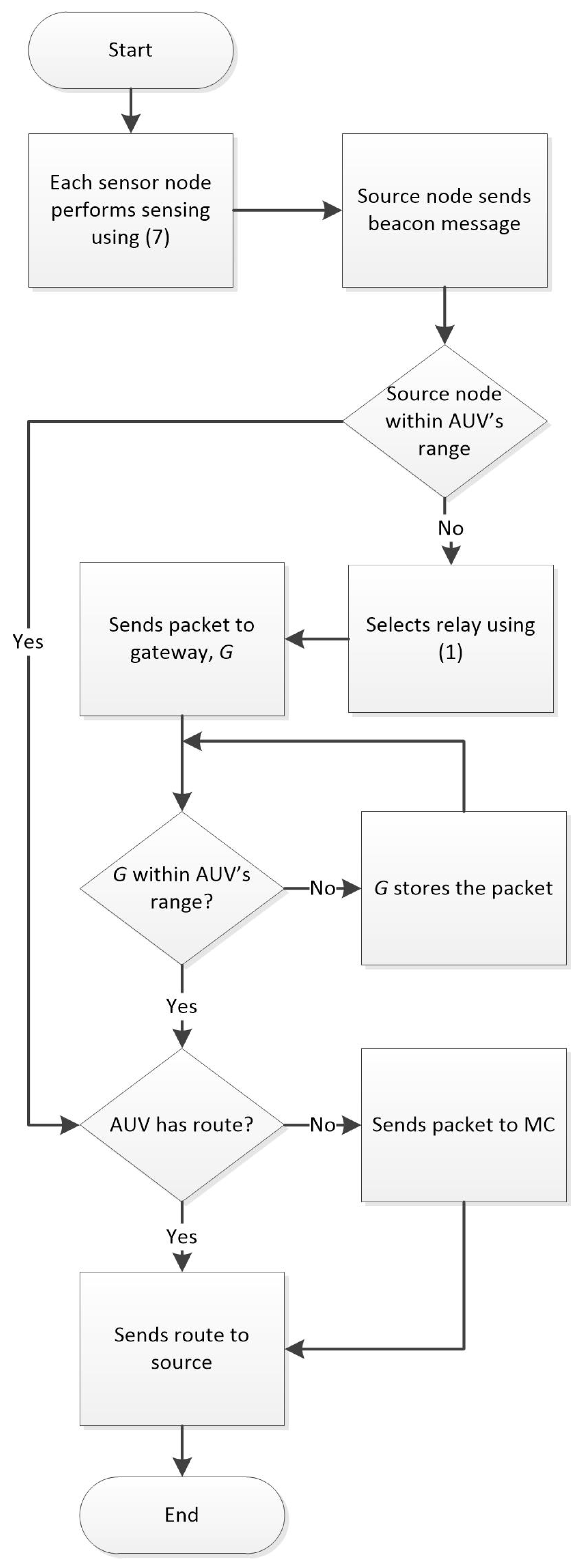
Now, the term in (1) and (4) shows the common idle channel between two communicating acoustic nodes that is free from PU activity. We explain the summary of the proposed algorithm by considering an example scenario, as shown in Figure 1. Assume that the MC and all LCs have the global and the localized view of the network, respectively. Source S is looking for a stable route to reach destination D. The source reaches gateway G by making hop-to-hop links using (1). G forwards the request packet to an LC. The LC checks its flow table and does not find a match. It forwards the packet to the MC, which calculates a stable route using (4). The MC sends this packet to the LC, which sends it back to the source node. The source finally forwards the data packet to the destination via the prescribed route. The flow chart of the complete algorithm is shown in Figure 2.
4. Performance Evaluation
We evaluated the performance of CA-SDUN in ns-MIRACLE [39] connected with a Bellhop channel simulator [38] via the World Ocean Simulation System (WOSS) [34] interface. We distributed randomly placed sensor nodes in a target area of 700 m × 700 m × 700 m, each having a transmission range of 100 m. The spectrum band (10–40 KHz) was divided into M = 5, and each channel was able to be occupied by a licensed PU. The bandwidth of each channel was 6 KHz, with carrier frequencies of {13, 19, 25, 31, 37} KHz. This means that a band of frequencies is free for use by legitimate users in order to transmit data packets over a number of free subcarriers. The total number of subcarriers, S, was 128, and each had carrier spacing of 46.875 Hz. As we know that channel sensing is affected by sensing time in any cognitive radio network, we therefore used fewer subcarriers to make it reasonable for underwater cognitive acoustic networks. For the same reason, we used the length of cyclic prefix at 12.4 ms, with symbol duration at 21.33 ms, which is greater than the typical value of the delay spread in underwater networks (i.e., approximately 11 ms [30]). The number of PUs moving randomly in the network was two. The number of AUVs used was two, each moving at a speed of 1.5 m/s and having a transmission range of 300 m. There was one MC placed at the surface of the ocean. The number of sensor nodes varied from 10 to 30. Packet size was assumed to be fixed (i.e., 64 bytes), and transmission power dB re Pa, which is within the range of the power value for acoustic signals of dolphins [27].
As argued in Section 2, there is no publicly known cognitive routing protocol for software-defined underwater networks that combines a cognitive capability with a routing technique by using the SDN approach. Therefore, we chose to compare CA-SDUN with two reference schemes (AA-RP [18] and DVRP [14]), each in combination with an energy detector-based spectrum sensing scheme [40] for underwater cognitive sensor networks. For simplicity, we denote these schemes as Cog-AA-RP and Cog-DVRP. AA-RP considers AUVs as mobile sinks that collect data from sensor nodes and forward the collected data to the surface. A gateway node (GN) is an agent of an AUV which communicates with the AUV when ordinary sensor nodes fail to make a connection. The GN stores information until it forwards it to the AUV. Cog-AA-RP modifies the AA-RP protocol such that each sensor node (including the GN and the AUV) first senses the spectrum and exchanges the local sensing results to find common idle channels. Finally, it implements the key idea of AA-RP to collect data to forward to the surface station. DVRP is a flood-based routing protocol for underwater sensor networks that forwards data packets (based on the flooding zone angle) from the sender nodes towards the surface of the ocean. It selects the next-hop node within the defined flooding zone. Like Cog-AA-RP, Cog-DVRP modifies the DVRP protocol such that each sensor node exchanges the spectrum sensing results within its defined zone in order to find a common idle channel. The two communicating nodes, having consensus about a common idle channel, then exchange data packets to establish a stable route between source and destination.
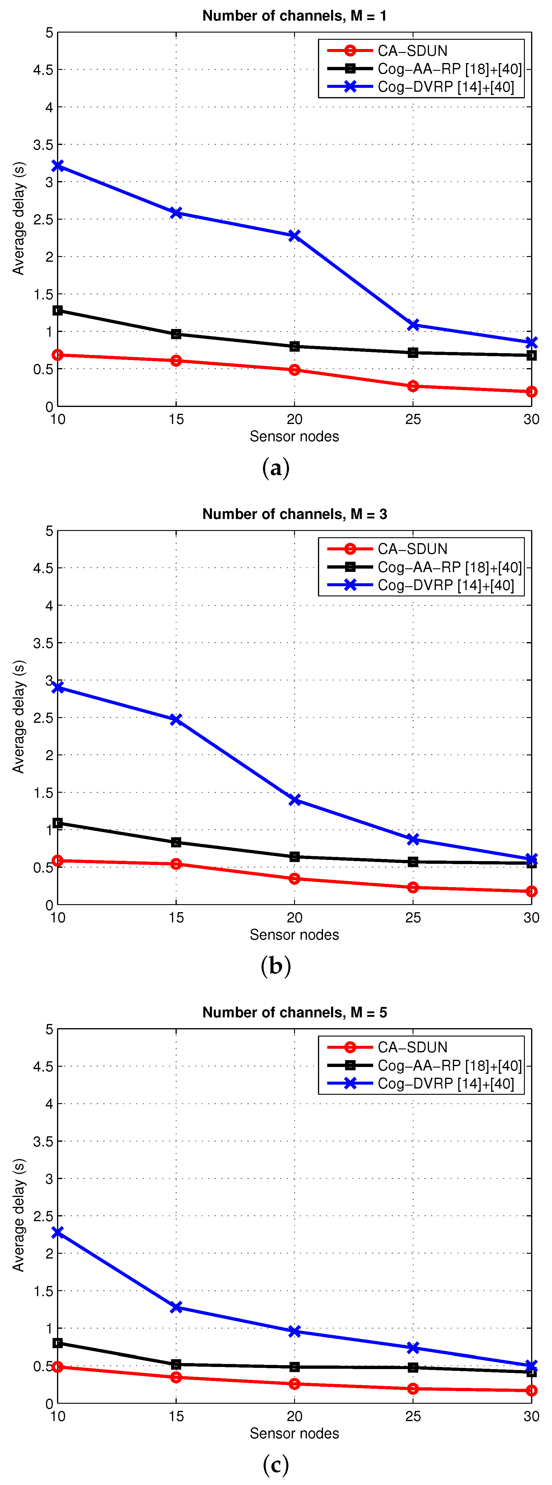
Figure 3 shows the performance of average delay as a function of the number of sensor nodes with the number of channels as a parameter. Average delay is defined as the average time required by a packet sent from the source node to reach the destination. The average delay decreases with an increase in the number of sensor nodes. The pattern is the same for the three schemes, i.e., when increasing the number of sensor nodes and increasing the number of channels, delay decreases. This is because the connectivity in the network increases with an increase in sensor nodes, and in the latter case, the large number of channels in the network increases the chances for the sensor nodes to have even more common idle subcarriers. With fewer sensor nodes, the delay is high for all the schemes because a packet usually has to wait longer than normal to find the next hop node. Moreover, finding a common idle channel in cognitive communications scenarios is another reason for packet delay. As our goal is to maintain network stability by providing the best route between source and destination, we therefore applied the SDN approach where controllers know the route to the destination by keeping an updated network topology. In CA-SDUN, considering that the AUVs on fixed trajectories serve as LCs further reduces the delay. When these LCs know the route to the destination, they reply to the gateway/querying node with the updated route without communicating with the MC, and thereby reduce network delay. On the other hand, AUVs in Cog-AA-RP select nodes based on the distance and neighbor information of the first-hop node after finding a common idle channel between two communicating nodes. Hence, CA-SDUN outperforms Cog-AA-RP because it allows each querying node to directly make a connection with the controller to get a stable route. Also, both CA-SDUN and Cog-AA-RP outperform Cog-DVRP. This is because Cog-DVRP restricts the neighboring set for the querying node. The querying node is bound to select a relay node within the flooding zone. As this is a cognitive routing scheme, the elementary step of selecting a common idle channel between two communicating nodes further degrades the performance of this reference scheme. As a result, finding a relay node within the flooding zone decreases network performance by reducing the number of sensor nodes.
Figure 4 shows the performance of packet delivery ratio as a function of the number of sensor nodes with the number of channels as a parameter. Packet delivery ratio is defined as the ratio of the number of packets delivered to the destination to the number of packets generated by the source node. The delivery ratio increases with an increase in the number of sensor nodes. The SDN approach in CA-SDUN improves network performance in terms of delivery ratio because of the logically centralized controller that dictates the behavior of the network. In Cog-DVRP, a querying node has to select the next node for every hop until it reaches the surface of the ocean. By doing so, it may come across several fragile links due to greater delay, resulting in link failures and a low packet delivery ratio. However, Cog-AA-RP outperforms Cog-DVRP because the AUV is responsible for forwarding data from sensor nodes to the surface of the ocean. Nevertheless, the selection of a GN by the AUV with the restriction of a common idle channel lowers the delivery ratio in comparison with CA-SDUN. In our scheme, the MC keeps the global view of the network, which means the MC manages all the information about idle channels and relay nodes. Therefore, by calculating the path duration, the MC provides the best stable route between source and destination to each querying node. In the cognitive underwater environment, in addition to underwater environmental challenges, another factor that affects the packet delivery ratio is the selection of a common idle channel. We can see from Figure 4 that increasing the number of channels increases the chance for the sensor nodes to have even more common idle subcarriers. However, for CA-SDUN, the packet delivery ratio is higher for different numbers of channels in comparison with the other two reference schemes. The reason is the selection of the relay node based on minimum transmission delay. When there is only a single channel in the network, there is a smaller number of idle subcarriers; hence, CA users face difficulty in accessing subcarriers free from a PU. Increasing the number of channels allows CA users to access the common idle sub-bands, and increases the chances for more sensor nodes to participate in the network. Hence, in this regard, the delivery ratio under CA-SDUN is the highest, compared to other scenarios, when the number of channels is M = 5, as shown in Figure 4c.
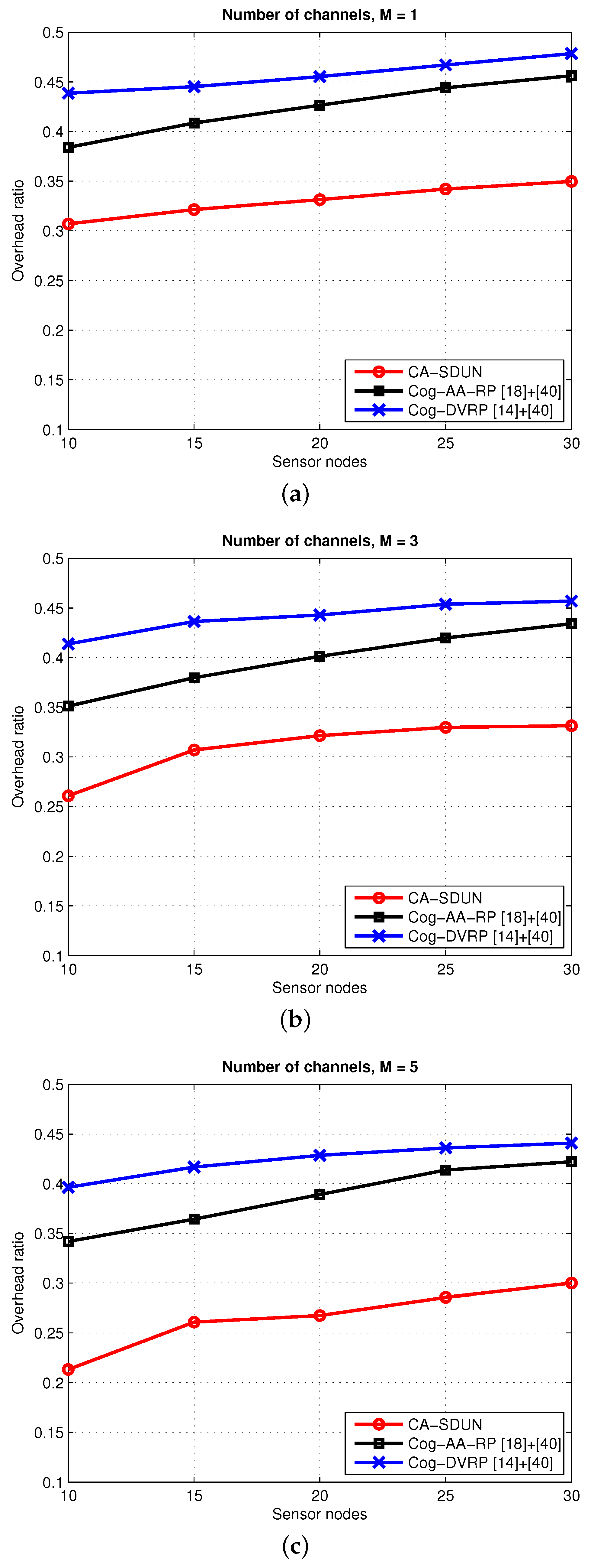
Figure 5 shows the overhead ratio of CA-SDUN, Cog-AA-RP, and Cog-DVRP as a function of the number of sensor nodes, with the number of channels as a parameter. Overhead ratio is defined as the ratio of the number of control packets to the total number of packets in the network. The routing overhead for the three schemes increases with an increasing number of sensor nodes in the network. We observed similarity in all the schemes in terms of an increase in overhead ratio when the number of sensor nodes increased and the number of channels decreased—the more sensor nodes, the higher the message update rate. However, CA-SDUN outperforms both reference schemes. This is because of the centralized controller, which reduces the number of control messages in the network. Each querying/gateway node in CA-SDUN communicates with the LCs whenever it encounters a packet mismatch or it requires a route update. When these LCs know the route to the destination, they reply to the querying nodes with the updated route without communicating with the MC, and thereby reduce the message rate. Moreover, in any case of an unstable link due to the unavailability of any sensor node or channel, the querying node directly asks the LC for a route update without sending the packet back to the source node. However, in the reference schemes, nodes send beacon messages to all neighboring nodes for each update on the network state. The overhead ratio for both Cog-AA-RP and Cog-DVRP is higher than for CA-SDUN. In Cog-AA-RP, the AUV sends hello messages to all the first-hop neighboring nodes to choose GNs in a timely manner, and these GNs exchange messages with sensor nodes to collect data; hence, a large overhead is incurred. On the other hand, in Cog-DVRP, calculating the flooding zone further reduces the chances of successful packet delivery. This is because sensor nodes may not find a common idle channel for communications, which therefore increases the overhead ratio. Figure 5 also shows that increasing the number of channels increases the free subcarriers in the network, and thereby decreases overhead by providing a larger number of unused subcarriers to all types of sensor node for stable communications. A complete analysis of our simulation results shows that the SDN-based scheme outperforms non–SDN-based schemes, and using AUVs in the network enhances network performance.
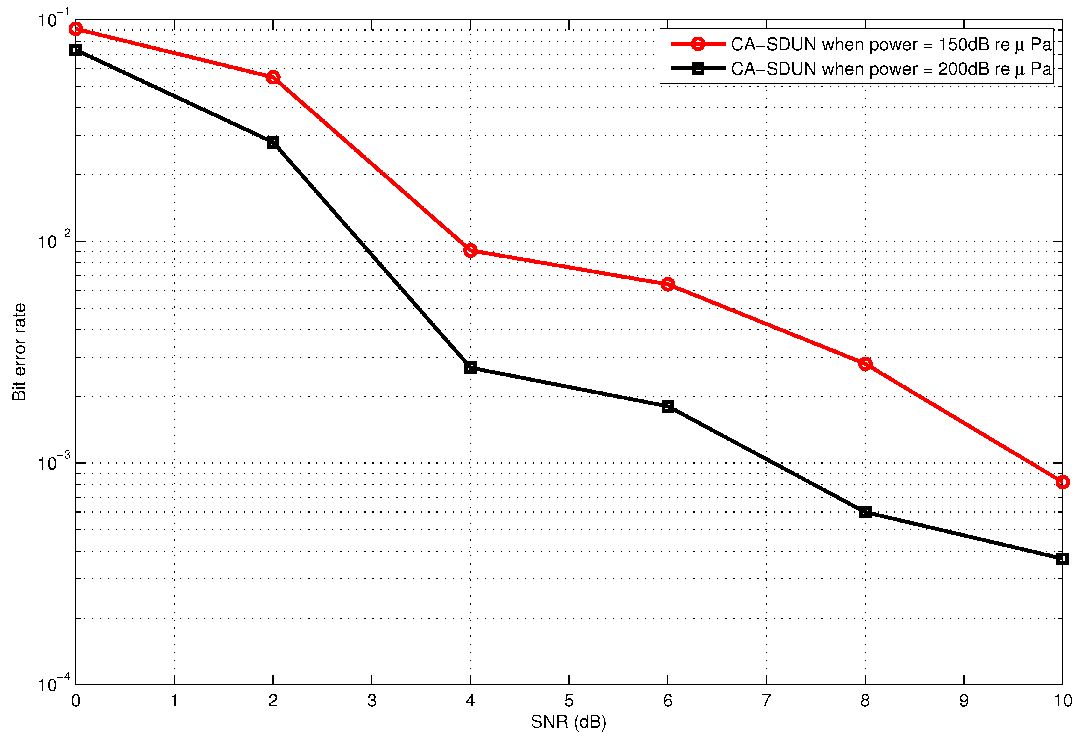
Figure 6 shows the data rate as a function of different frequencies with the bandwidth as a parameter. The data rate decreases dramatically with increasing frequencies because the path loss increases with an increase in frequency. However, increasing the bandwidth improves the data rate, but the operating region for majority of acoustic systems has limited bandwidth in underwater networks due to strong attenuation. Therefore, we achieve a low data rate for low bandwidth. Figure 7 shows the relationship between bit error rate and various SNR values. Bit error rate is used to determine the quality of transmitted signal in a channel. The lower the bit error rate, the better the quality of the received signal. It can be seen from the curve that the bit error rate improves with the increase in SNR and transmission power.
5. Conclusions
In this paper, we proposed a novel routing protocol for cognitive acoustic software-defined underwater networks. The idea of combining a cognitive capability with a routing scheme in software-defined underwater networks makes this protocol unique. The protocol has two phases: beaconing and route estimation. A main controller is responsible for network management, while AUVs serving as local controllers move on fixed trajectories to reduce the number of control messages and any network delay. The controllers are responsible for providing a stable route between source and destination for the querying node. A link is formed between two nodes if they have a consensus about a common idle channel, and a link with the minimum duration is selected to make a stable route. Both natural acoustic systems and artificial acoustic systems are considered to be PUs in this scheme. Therefore, spectrum sensing is performed with an OFDM-based energy detection scheme. Our results show better performance for average delay, packet delivery ratio, and routing overhead ratio.
For sensing channels and then selecting relay, a large amount of energy is required in the proposed scheme. Therefore, it is an urgent problem to consider a good trade-off among energy consumption, overhead, and delay for cognitive routing schemes based on traffic and energy balancing. Also, energy harvesting techniques, such as harvesting energy from acoustic links to recharge sensors/AUV batteries, should be considered to prolong the network lifetime. We have left these research issues for future work.
Acknowledgments
This work was supported by the National Research Foundation of Korea funded by the MEST under Grant NRF 2015R1A2A1A15053452 and NRF 2016K2A9A1A01950711.
Author Contributions
Huma Ghafoor and Insoo Koo proposed, analyzed, designed and contributed to writing the research idea all together.
Conflicts of Interest
The authors declare no conflict of interest.
References
- Lal, C.; Petroccia, R.; Pelekanakis, K.; Conti, M.; Alves, J. Toward the Development of Secure Underwater Acoustic Networks. IEEE J. Ocean. Eng. 2017, 42, 1075–1087. [Google Scholar] [CrossRef]
- Luo, Y.; Pu, L.; Zuba, M.; Peng, Z.; Cui, J.-H. Cognitive Acoustics: Making Underwater Communications Environment-friendly. In Proceedings of the International Conference on Underwater Networks and Systems, Rome, Italy, 12–14 November 2014. [Google Scholar]
- Luo, Y.; Pu, L.; Zuba, M.; Peng, Z.; Cui, J.-H. Challenges and Opportunities of Underwater Cognitive Acoustic Networks. IEEE Trans. Emerg. Top. Comput. 2014, 2, 198–211. [Google Scholar] [CrossRef]
- Wang, J.; Ma, L.; Chen, W. Design of underwater acoustic sensor communication systems based on software-defined networks in big data. Int. J. Distrib. Sens. Netw. 2017, 13, 1–14. [Google Scholar] [CrossRef]
- Xu, H.; Li, X.-Y.; Huang, L.; Deng, H.; Huang, H.; Wang, H. Incremental Deployment and Throughput Maximization Routing for a Hybrid SDN. IEEE/ACM Trans. Netw. 2017, 99, 1–15. [Google Scholar] [CrossRef]
- Fan, R.; Goldrick, C.; Gerla, M. An SDN Architecture for Underwater Search and Surveillance. In Proceedings of the 13th Annual Conference on Wireless On-Demand Network Systems and Services, Jackson, WY, USA, 21–24 February 2017; pp. 96–99. [Google Scholar]
- Yan, H.; Shi, Z.; Cui, J.-H. DBR: Depth-Based Routing for Underwater Sensor Networks. In Proceedings of the 7th International IFIP-TC6 Networking Conference on Adhoc and Sensor Networks, Wireless Networks, Next Generation Internet, Singapore, 5–9 May 2008; pp. 72–86. [Google Scholar]
- Lee, U.; Wang, P.; Noh, Y.; Vieira, L.; Gerla, M.; Cui, J.-H. Pressure Routing for Underwater Sensor Networks. In Proceedings of the IEEE INFOCOM, San Diego, CA, USA, 14–19 March 2010. [Google Scholar]
- Noh, Y.; Lee, U.; Wang, P.; Choi, B.S.C.; Gerla, M. VARP: Void Aware Pressure Routing for Underwater Sensor Networks. IEEE Trans. Mob. Comput. 2013, 12, 895–908. [Google Scholar] [CrossRef]
- Pompili, D.; Melodia, T.; Akyildiz, I.F. Distributed Routing Algorithms for Underwater Acoustic Sensor Networks. IEEE Trans. Wirel. Commun. 2010, 9, 2934–2944. [Google Scholar] [CrossRef]
- Basagni, S.; Petrioli, C.; Petroccia, R.; Spaccini, D. Channel-aware Routing for Underwater Wireless Networks. In Proceedings of the IEEE OCEANS, Yeosu, Korea, 21–24 May 2012. [Google Scholar]
- Yoon, S.; Azad, A.K.; Oh, H.; Kim, S. AURP: An AUV-aided underwater routing protocol for underwater acoustic sensor networks. Sensors 2012, 12, 1827–1845. [Google Scholar] [CrossRef] [PubMed]
- Carlson, E.A.; Beaujean, P.-P.J.; An, E. Location-Aware Source Routing Protocol for Underwater Acoustic Networks of AUVs. J. Electr. Comput. Eng. 2012, 2012, 1–18. [Google Scholar] [CrossRef]
- Ali, T.; Jung, L.T.; Faye, I. Diagonal and Vertical Routing Protocol for Underwater Wireless Sensor Network. Procedia Soc. Behav. Sci. 2014, 129, 372–379. [Google Scholar] [CrossRef]
- Coutinho, R.W.L.; Boukerche, A.; Vieira, L.F.M.; Loureiro, A.A. GEDAR: Geographic and opportunistic routing protocol with depth adjustment for mobile underwater sensor networks. In Proceedings of the IEEE International Conference on Communications, Sydney, Australia, 10–14 June 2014. [Google Scholar]
- Ilyas, N.; Alghamdi, T.; Farooq, M.; Mehboob, B.; Sadiq, A.; Qasim, U.; Khan, Z.; Javaid, N. AEDG: AUV-aided Efficient Data Gathering Routing Protocol for Underwater Wireless Sensor Networks. Procedia Comput. Sci. 2015, 52, 568–575. [Google Scholar] [CrossRef]
- Rani, J.M.; Talwar, R. Energy efficient chain based cooperative routing protocol for WSN. Appl. Soft Comput. 2015, 35, 386–397. [Google Scholar] [CrossRef]
- Zhuo, W.; Hongmei, G.; Longjie, J.; Xiaoning, F. AUV-aided communication method for underwater mobile sensor network. In Proceedings of the IEEE OCEANS, Shanghai, China, 10–13 April 2016; pp. 1–7. [Google Scholar]
- Luo, Y.; Pu, L.; Mo, H.; Zhu, Y.; Peng, Z.; Cui, J.-H. Dynamic Control Channel MAC for Underwater Cognitive Acoustic Networks. In Proceedings of the IEEE INFOCOM, San Francisco, CA, USA, 10–14 April 2016. [Google Scholar]
- Luo, Y.; Pu, L.; Mo, H.; Zhu, Y.; Peng, Z.; Cui, J.-H. Receiver-Initiated Spectrum Management for Underwater Cognitive Acoustic Network. IEEE Trans. Mob. Comput. 2017, 16, 198–212. [Google Scholar] [CrossRef]
- Li, X.; Sun, Y.; Guo, Y.; Fu, X.; Pan, M. Dolphins First: Dolphin-Aware Communications in Multi-hop Underwater Cognitive Acoustic Networks. IEEE Trans. Wirel. Commun. 2017, 16, 2043–2056. [Google Scholar] [CrossRef]
- Ghafoor, H.; Noh, Y.; Koo, I. OFDM-based Spectrum-Aware Routing in Underwater Cognitive Acoustic Networks. IET Commun. 2017. [Google Scholar] [CrossRef]
- Akyildiz, I.F.; Wang, P.; Lin, S.-C. Softwater: Software-defined networking for next-generation underwater communication systems. Ad Hoc Netw. 2016, 46, 1–11. [Google Scholar] [CrossRef]
- Demirors, E.; Shi, J.; Guida, R.; Melodia, T. SEANet G2: Toward a High-Data-Rate Software-Defined Underwater Acoustic Networking Platform. In Proceedings of the ACM WUWNET’16, Shanghai, China, 24–26 October 2016. [Google Scholar]
- Lal, C.; Petroccia, R.; Conti, M.; Alves, J. Secure Underwater Acoustic Networks: Current and Future Research Directions. In Proceedings of the IEEE UComms, Lerici, Italy, 30 August–1 September 2016. [Google Scholar]
- Ding, L.; Melodia, T.; Batalama, S.N.; Matyjas, J.D.; Medley, M.J. Cross-Layer Routing and Dynamic Spectrum Allocation in Cognitive Radio Ad Hoc Networks. IEEE Trans. Veh. Technol. 2010, 59, 1969–1979. [Google Scholar] [CrossRef]
- Erbe, C.; Reichmuth, C.; Cunningham, K.; Lucke, K.; Dooling, R. Communication masking in marine mammals: A review and research strategy. Mar. Pollut. Bull. 2016, 103, 15–38. [Google Scholar] [CrossRef] [PubMed]
- Mellinger, D.K.; Clark, C.W. MobySound: A reference archive for studying automatic recognition of marine mammal sounds. Appl. Acoust. 2006, 67, 1226–1242. [Google Scholar] [CrossRef]
- Axell, E.; Larsson, E.G. Optimal and Sub-Optimal Spectrum Sensing of OFDM Signals in Known and Unknown Noise Variance. IEEE J. Sel. Areas Commun. 2011, 29, 290–304. [Google Scholar] [CrossRef]
- Stojanovic, M.; Preisig, J. Underwater Acoustic Communication Channels: Propagation Models and Statistical Characterization. IEEE Commun. Mag. 2009, 47, 84–89. [Google Scholar] [CrossRef]
- Stojanovic, M. On the relationship between capacity and distance in an underwater acoustic communication channel. ACM SIGMOBILE Mob. Comput. Commun. Rev. 2007, 11, 34–43. [Google Scholar] [CrossRef]
- Berkhovskikh, L.; Lysanov, Y. Fundamentals of Ocean Acoustics; Springer: Berlin/Heidelberg, Germany, 1982. [Google Scholar]
- Casari, P.; Tapparello, C.; Guerra, F.; Favaro, F.; Calabrese, I.; Toso, G.; Azad, S.; Masiero, R.; Zorzi, M. Open-source Suites for Underwater Networking: WOSS and DESERT Underwater. IEEE Netw. 2014, 28, 38–46. [Google Scholar] [CrossRef]
- Guerra, F.; Casari, P.; Zorzi, M. World Ocean Simulation System (WOSS): A Simulation Tool for Underwater Networks with Realistic Propagation Modeling. In Proceedings of the 4th ACM International Workshop on Underwater Networks (WuWNeT), Berkeley, CA, USA, 3 November 2009. [Google Scholar]
- Qarabaqi, P.; Stojanovic, M. Statistical Characterization and Computationally Efficient Modeling of a Class of Underwater Acoustic Communication Channels. IEEE J. Ocean. Eng. 2013, 38, 701–717. [Google Scholar] [CrossRef]
- Toso, G.; Casari, P.; Zorzi, M. The Effect of Different Attenuation Models on the Performance of Routing in Shallow-Water Networks. In Proceedings of the Underwater Communications and Networking (UComms), Sestri Levante, Italy, 3–5 September 2014; pp. 1–5. [Google Scholar]
- Bahrami, N.; Khamis, N.H.H.; Baharom, A.B. Study of Underwater Channel Estimation Based on Different Node Placement in Shallow Water. IEEE Sens. J. 2016, 16, 1095–1102. [Google Scholar] [CrossRef]
- Porter, M.B. Bellhop Code. Available online: http://oalib.hlsresearch.com/Rays/index.html (accessed on May 2016).
- Baldo, N.; Miozzo, M.; Guerra, F.; Rossi, M.; Zorzi, M. MIRACLE: The Multi-Interface Cross-Layer Extension of ns2. EURASIP J. Wirel. Commun. Netw. 2010, 2010. [Google Scholar] [CrossRef]
- Wang, N.; Gao, Y.; Cuthbert, L. Spectrum Sensing Using Adaptive Threshold based Energy Detection for OFDM Signals. In Proceedings of the IEEE International Conference on Communication Systems (ICCS), Macau, China, 19–21 November 2014; pp. 359–363. [Google Scholar]
Figure 1.
Cognitive acoustic software-defined underwater network (CA-SDUN). SDN: software-defined networking; PU: primary user.
Figure 1.
Cognitive acoustic software-defined underwater network (CA-SDUN). SDN: software-defined networking; PU: primary user.

Figure 2.
A flowchart representing the CA-SDUN protocol. MC: main controller.

Figure 3.
Performance comparison between CA-SDUN, Cog-AA-RP, and Cog-DVRP for average delay as a function of the number of sensor nodes with different numbers of channels, M. (a) average delay when M = 1; (b) average delay when M = 3; and (c) average delay when M = 5. CA-SDUN: cognitive acoustic software-defined underwater network; Cog-AA-RP: cognitive AUV-aided routing method integrated path planning; Cog-DVRP: cognitive diagonal and vertical routing protocol; AUV: autonomous underwater vehicle.

Figure 4.
Performance comparison between CA-SDUN, Cog-AA-RP, and Cog-DVRP for the packet delivery ratio as a function of the number of sensor nodes with different numbers of channels, M. (a) packet delivery ratio when M = 1; (b) packet delivery ratio when M = 3; and (c) packet delivery ratio when M = 5. CA-SDUN: cognitive acoustic software-defined underwater network; Cog-AA-RP: cognitive AUV-aided routing method integrated path planning; Cog-DVRP: cognitive diagonal and vertical routing protocol; AUV: autonomous underwater vehicle.

Figure 5.
Performance comparison between CA-SDUN, Cog-AA-RP, and Cog-DVRP for overhead ratio as a function of the number of sensor nodes with different numbers of channels, M. (a) overhead ratio when M = 1; (b) overhead ratio when M = 3; and (c) overhead ratio when M = 5. CA-SDUN: cognitive acoustic software-defined underwater network; Cog-AA-RP: cognitive AUV-aided routing method integrated path planning; Cog-DVRP: cognitive diagonal and vertical routing protocol; AUV: autonomous underwater vehicle.

Figure 6.
Data rate as a function of different frequencies. CA-SDUN: cognitive acoustic software-defined underwater network.
Figure 6.
Data rate as a function of different frequencies. CA-SDUN: cognitive acoustic software-defined underwater network.

Figure 7.
Bit error rate as a function of signal-to-noise-ratio (SNR). CA-SDUN: cognitive acoustic software-defined underwater network.
Figure 7.
Bit error rate as a function of signal-to-noise-ratio (SNR). CA-SDUN: cognitive acoustic software-defined underwater network.


Table 1.
Comparison of related schemes. SDUN: software-defined underwater network; UAN: underwater acoustic network; UCAN: underwater cognitive acoustic network; DBR: depth-based routing; VAPR: void-aware pressure routing; CARP: channel-aware routing protocol; AURP: AUV-aided underwater routing protocol; LASR: location-aware source routing;DVRP: diagonal and vertical routing protocol; GEDAR: geographic and opportunistic routing protocol with depth adjustment-based topology control for communication recovery; AEDG: AUV-aided efficient data-gathering; AA-RP: AUV-aided routing method integrated path planning; DCC-MAC: dynamic control channel medium access control; RISM: receiver-initiated spectrum management; OSAR: orthogonal frequency division multiplexing (OFDM)-based spectrum-aware routing; AUV: autonomous underwater vehicle.
| Protocols | Proposed for UANs? | Proposed for UCANs? | Proposed for SDUN? | Routing in UANs? | Cognitive Routing in UANs? | Cognitive Routing in SDUN? |
|---|---|---|---|---|---|---|
| DBR [7] | ✓ | ✗ | ✗ | ✓ | ✗ | ✗ |
| [8] | ✓ | ✗ | ✗ | ✓ | ✗ | ✗ |
| VAPR [9] | ✓ | ✗ | ✗ | ✓ | ✗ | ✗ |
| [10] | ✓ | ✗ | ✗ | ✓ | ✗ | ✗ |
| CARP [11] | ✓ | ✗ | ✗ | ✓ | ✗ | ✗ |
| AURP [12] | ✓ | ✗ | ✗ | ✓ | ✗ | ✗ |
| LASR [13] | ✓ | ✗ | ✗ | ✓ | ✗ | ✗ |
| DVRP [14] | ✓ | ✗ | ✗ | ✓ | ✗ | ✗ |
| GEDAR [15] | ✓ | ✗ | ✗ | ✓ | ✗ | ✗ |
| AEDG [16] | ✓ | ✗ | ✗ | ✓ | ✗ | ✗ |
| [17] | ✓ | ✗ | ✗ | ✓ | ✗ | ✗ |
| AA-RP [18] | ✓ | ✗ | ✗ | ✓ | ✗ | ✗ |
| DCC-MAC [19] | ✗ | ✓ | ✗ | ✗ | ✗ | ✗ |
| RISM [20] | ✗ | ✓ | ✗ | ✗ | ✗ | ✗ |
| [21] | ✗ | ✓ | ✗ | ✗ | ✗ | ✗ |
| OSAR [22] | ✗ | ✓ | ✗ | ✗ | ✓ | ✗ |
| SoftWater [23] | ✓ | ✗ | ✓ | ✗ | ✗ | ✗ |
| [4] | ✓ | ✗ | ✓ | ✗ | ✗ | ✗ |
| SEANet G2 [24] | ✓ | ✗ | ✓ | ✗ | ✗ | ✗ |
| [25] | ✓ | ✓ | ✓ | ✗ | ✗ | ✗ |
© 2017 by the authors. Licensee MDPI, Basel, Switzerland. This article is an open access article distributed under the terms and conditions of the Creative Commons Attribution (CC BY) license (http://creativecommons.org/licenses/by/4.0/).
Share and Cite
MDPI and ACS Style
Ghafoor, H.; Koo, I. Cognitive Routing in Software-Defined Underwater Acoustic Networks. Appl. Sci. 2017, 7, 1312. https://0-doi-org.brum.beds.ac.uk/10.3390/app7121312
AMA Style
Ghafoor H, Koo I. Cognitive Routing in Software-Defined Underwater Acoustic Networks. Applied Sciences. 2017; 7(12):1312. https://0-doi-org.brum.beds.ac.uk/10.3390/app7121312
Chicago/Turabian StyleGhafoor, Huma, and Insoo Koo. 2017. "Cognitive Routing in Software-Defined Underwater Acoustic Networks" Applied Sciences 7, no. 12: 1312. https://0-doi-org.brum.beds.ac.uk/10.3390/app7121312
Note that from the first issue of 2016, this journal uses article numbers instead of page numbers. See further details here.