Article

Design and Cooling Performances of an Air Conditioning System with Two Parallel Refrigeration Cycles for a Special Purpose Vehicle

Lee Department of Mechanical Engineering, Dong-A University, Busan 604-714, Korea
Submission received: 7 December 2016 / Accepted: 13 February 2017 / Published: 15 February 2017
(This article belongs to the Section Energy Science and Technology)

Abstract

:
The objective of this study is to design and briefly investigate the cooling performances of an air conditioning system for a special purpose vehicle under various experimental conditions. An air conditioning system with two parallel refrigeration cycles consisting of two compressors and two condensers for satisfying the required cooling performance of the special purpose vehicle was tested under extremely hot weather conditions and high thermal load conditions and then optimized by varying the refrigerant charge amount. The optimum refrigerant charge amount of the tested air conditioning system was 1200 g with the consideration of the cooling speed and cooling capacity. The indoor temperatures of the suggested air conditioning system at the refrigerant charge amounts of 1200 g, 1400 g, and 1600 g were 24.7 °C, 25.2 °C, and 26.4 °C, respectively, at the elapsed time of 300 s. The cooling time required to reach a 15.0 °C inner temperature in the suggested air conditioning system increased by 13.3% with the decrease of the refrigerant charge amount from 1600 g to 1200 g. The cooling capacity and the coefficient of performance (COP) of the suggested air conditioning system increased by 37.9% and 10.9%, respectively, due to a decrease of the refrigerant charge amount from 1600 g to 1200 g. The observed cooling performance characteristics of the air conditioning system with two parallel refrigeration cycles means it could be suitable for cabin cooling of special purpose vehicles. In addition, the designed special air conditioning system with two parallel refrigeration cycles for a special purpose vehicle was built to ensure a sufficient cooling performance for equipped passengers.

1. Introduction

With an increase in the thermal comfort for passenger cabins and intelligent driving for easy driver control and convenience, many smart and green passenger vehicles have been developed and researched by various automotive makers [1,2]. In addition, advanced automotive technology, with the modernization of the transportation industry, seeks to improve the comfort and convenience of the driver. Accordingly, numerous advanced air conditioning systems and heating systems for cabin heating and cooling of passenger vehicles have been studied to improve the thermal comfort and air conditioning room for individual passengers, including drivers of passenger vehicles [3,4]. Meanwhile, the research and development on an air conditioning system for a cabin for a special purpose vehicle, which is frequently used under severe thermal load and weather conditions, is scarce because of lower production rate and low numbers of manufacturing companies. In this study, the special purpose vehicle is used under both extremely severe weather conditions such as in Southeast Asia and the tropical equatorial regions, and combat policemen equipped with thick protective clothing for demonstration crash and suppression were onboard. In particular, an advanced air conditioning system with high cooling performance for cabin cooling of the special purpose vehicle is required to ensure the sufficient cooling capacity due to the usage with severe thermal load conditions. The combat policemen caused the high cooling loads with respect to the air conditioning system. Therefore, the air conditioning system design of the special purpose vehicle operated under harsh environments is more important for resolving the extremely higher thermal loads. Generally, the air conditioning system design used for a special purpose vehicle involves similar steps to those of the normal passenger vehicles. Before design of an air conditioning system for cabin cooling, one should consider the thermal loads, including the external environments, driving conditions, and heat generation by passengers. Also, the narrow space and space limitation of the compartment for vehicles cause thermal aggregation and ineffective ventilation by preventing the flow of air [5]. Numerous studies on performance evaluations and enhancements of the conventional air conditioning system for passenger vehicles have been published in the open literature. Kim et al. (2007) carried out an experimental research on the performance characteristics of the refrigeration system using R-134a. They analyzed the performance characteristics and suggested the superheat control method for improving the energy efficiency of the tested refrigeration system [6]. Jang et al. (2012) studied improvements in plate heat exchanger performance distributed by R-134a in the evaporator. They reported that the heat transfer coefficient with the advanced distributed refrigerant flow rate was improved up to 10% [7]. Sin et al. (2012) studied cooling performances of the refrigeration system for a refrigerator truck with the change of refrigerants R-404a and R-134a. They reported that the system performances decreased with the increase of the outdoor temperatures due to a rise in the power consumption and reduction of the refrigerating capacity [8]. Tamura et al. (2005) tested the automotive cooling and heating air conditioning system using CO2 with the heat pump method. They developed a highly efficient automotive cooling and heating air conditioning system using the waste heat released by the heat pump cycles during dehumidification. In addition, the developed system achieves the same cooling performance as a conventional automotive air conditioning system using R-134a [9]. Tuo and Hrnjak (2012) studied the performances of an automotive air conditioning system using R134a in direct expansion (DX) mode and flash gas bypass (FGB) mode. They reported that the cooling capacity and coefficient of performance (COP) of the designed system in FGB mode were improved 13%–18% and 4%–7%, respectively, compared with that of the DX mode [10]. Qi et al. (2010) investigated experimentally on performance enhancement of an automotive air conditioning system using newly developed micro-channel heat exchangers with lower weight and volume compared with conventional and currently used heat exchangers. They reported that the COP of the designed system under all the other test conditions except the idle condition was higher than that of the conventional system. In addition, the cooling capacity of the designed system increased by 5% and the COP improved by 7.9% under high vehicle speed [11]. Lee and Jung (2012) studied the performances of R1234yf and R134a in a heat pump bench tester under the conditions for automotive air-conditioners. They performed the ‘drop-in’ tests under summer and winter conditions with R1234yf and R-134a in a bench tester equipped with an open type compressor for automotive air conditioning systems. They reported that the COP and the cooling capacity of R1234yf are 2.7%–4.0% lower than those of R-134a, respectively [12]. Also, Zindove et al. [13] conducted a weathering test on interior automotive components under high temperature condition.
Previous studies on automotive air conditioning systems for cabin cooling in the vehicles have focused on the conventional passenger vehicles, including small- and medium-size or light- and heavy-duty vehicles. However, the research on the performance evaluation of the air conditioning system for special purpose vehicles has been limited in the open literature. Therefore, the objective of this study is to design and experimentally investigate the cooling performance characteristics of the air conditioning system for a special purpose vehicle under extremely hot weather conditions and higher thermal load conditions caused by equipped passengers. In addition, the special air conditioning system with two parallel refrigeration cycles for a special purpose vehicle was built to ensure a sufficient cooling performance for equipped passengers.
The paper is divided into four sections: introduction of the problem statement, experimental setup and configuration, results and discussion, and conclusion. The experimental setup section discusses the system configuration, data reduction, thermal load and air flow rate evaluation. Refrigerant enthalpy method has been used for calculations and the results for cooling performance of air conditioning are discussed using COP (for steady state performance) and cooling speed (for transient state performance). This paper is an extended version with updated results of the conference paper presented at 6th International Conference on Experiments/Process/System Modeling/Simulation/Optimization (IC-EpsMsO, Athens, Greece) in 2015.

2. Experimental Setup and Configuration

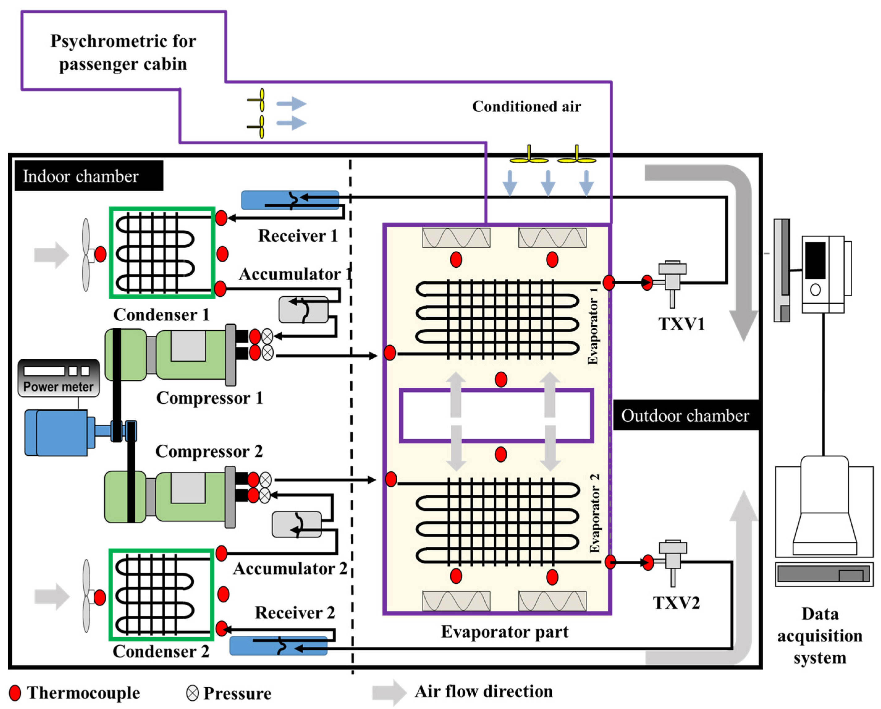
2.1. System Configuration

2.1.1. Set-Up

Figure 1 shows the schematic diagram of the experimental set-up for evaluating the cooling performances of the air-conditioning system with the two parallel refrigeration cycles for a special purpose vehicle. The experiments were performed and analyzed in the psychrometric chambers. The psychrometric unit consists of two chambers to control temperature and humidity conditions, respectively, as shown in Figure 1. The psychrometric chambers were controlled by using a proportional integral differential (PID) control, and the two chambers were equipped with temperature and humidity devices which comprised a cooling coil, a heating coil and a humidifier, to control the temperature and humidity settings of the air with an accuracy of ±0.2 °C. The temperature range for the psychometric chamber was −30 to 60 °C. The humidity range for psychometric chamber was 30%–95% RH (relative humidity) with humidity accuracy of ±5%. The measurements of the psychrometric chamber for the indoor compartment and the psychrometric chamber for the outdoor compartment were 4000 mm (length) × 2300 mm (width) × 2300 mm (height) and 7000 mm (length) × 2300 mm (width) × 2300 mm (height), respectively. The position of indoor chamber and outdoor chamber is highlighted in the schematic as shown. Both compartments were equipped with the PTC (positive temperature coefficient) heater and the refrigeration system for controlling the temperature and humidity conditions during the experiments and for reaching the required cooling capacity.
In this study, an air conditioning system with two parallel refrigeration cycles for the special purpose vehicle was designed using R-134a. In the tested air conditioning system with two parallel refrigeration cycles, two reciprocating compressors with a displacement volume of 160.0 cm3·rev−1 at 380 V were installed and driven by the electric motor of 8.0 kW, since each reciprocating compressor connected to the electric motor. Two thermostatic expansion valves (TEV) were positioned in front of the evaporator part. In order to ensure adequate sub-cooling and prevent vapor expansion, the two receiver tanks with a height of 320.0 mm and a diameter of 120.0 mm were used and installed at the outlet of the condenser part. Two accumulators with a height of 180.0 mm and a diameter of 120.0 mm were located in front of the two compressors to prevent the liquid refrigerant flows into the compressor inlet. Table 1 shows the specifications of the air-conditioning system with the two parallel refrigeration cycles for a special purpose vehicle.
Figure 2 shows the schematic diagrams of the condenser part and evaporator part of the two parallel refrigeration cycles for the air conditioning system of the special purpose vehicle. Figure 2a shows the configuration and air flow mechanism of the evaporator part of the air conditioning system for the special purpose vehicle. The evaporator part with measurements of 1100 mm (length) × 920 mm (width) × 220 mm (height) located at the indoor compartment had four fans with radial type and two heat exchangers. Size of the heat exchanger with an aluminum plate fin was 850 mm (length) × 160 mm (width) × 163 mm (height) and fin pitch was 2.0 mm. The fan of the evaporator part was multi-blade type. The fans applied to one section of the evaporator part circulated the air to the inner space through the middle hole of the evaporator part, as shown in Figure 2a. The cold air passing the evaporator is distributed into the outlet ports of the evaporator part. Figure 2b shows the configuration and the air flow mechanism of the condenser part of the air conditioning system for the special purpose vehicle. The condenser part located at the indoor compartment had one fan and one heat exchanger. The measurements of the heat exchanger with an aluminum groove fin were 820 mm (length) × 52 mm (width) × 270 mm (height). The fan of the condenser part was axial and propeller type. The fans applied to the condenser part circulated the air to the outside space as shown in Figure 2b. In particular, the suggested air flow mechanism of the evaporator part was optimized for the designed air conditioning system of the special purpose vehicle, effectively supplying the cooled air to the cabin of the combat policemen or equipped passengers.

2.1.2. Test Conditions

Table 2 shows the test conditions for evaluating the cooling performances of the air-conditioning system with the two parallel refrigeration cycles for a special purpose vehicle. The air temperatures indoors at a relative humidity of 50% was varied within a range of 25.0 °C. The compressor speed was fixed at 2700 rev·min−1. The refrigerant charge of the tested air conditioning system for seeking the optimum operation of the two parallel refrigeration cycles was varied within a range of 1200 g to 1600 g, with an interval of 200 g. The air temperatures for outdoors was set to 40.0 °C, reflecting the average temperature in the hot seasons in Southeast Asia and the tropical equatorial regions due to the locations near the equator, as shown in Table 3 [14]. The developed air conditioning system with two parallel refrigeration cycles was originally designed for use in the hot seasons in Southeast Asia and the tropical equatorial regions. Table 3 shows the average outdoor temperatures of the Southeast Asian region.

2.2. Data Reduction

Table 4 shows the uncertainties of the experimental parameters and measured data. Thermocouples with an accuracy of ±0.1 °C were used to measure the refrigerant-side and air-side temperatures, and digital pressure gauges with an accuracy of ±0.1% were installed to measure the refrigerant-side pressure. The mass flow rate of the Coriolis type flow meter was measured with an accuracy of ±0.2% of the reading. A data logger of a digital power meter type with an accuracy of ±0.5% was used to measure the electric power consumed by an electric motor used for driving two compressors. The precision limits and bias limits of all the parameters associated with cooling capacity and COP were estimated in uncertainty analysis. The average uncertainties of the experimental data on cooling capacity and the COP were determined to be 3.5% and 4.7%, respectively, using the method suggested by Moffat [15].
Based on the measured data, the heat transfer rate of the refrigerant-side was calculated by Equation (1) using the refrigerant enthalpy method (ASHRAE Standard 116, 1983) [16]. The cooling capacity of the evaporator part was calculated by Equation (2) using both the air flow rate and temperature difference suggested by Kim et al. (2009) [17]. The air-side cooling capacity of the evaporator part was validated against the refrigerant-side heat transfer rate of the evaporator part. The cooling capacity of the air-side was consistent with the heat transfer rate of the refrigerant-side within ±5.0%, so the present experimental setup was found to be appropriate.
Q ˙ r e f = m ˙ r e f Δ h r e f
Q ˙ e v a p = C a i r V ˙ a i r ρ a i r ( T air , out T air , in )
The compressor work was calculated by Equation (3) using the refrigerant enthalpy method. The COP (coefficient of performance) of the tested air conditioning system was calculated by Equation (4) using the air-side cooling capacity of the evaporator part and the compressor work.
W c o m p = m ˙ r e f ( h c o m p , o u t h c o m p , i n )
COP = Q e v a p W c o m p
Both the cooling capacity and the COP as the steady state performance and cooling speed of the cabin as a transient performance were evaluated, and the cooldown speed to reach a target temperature for the cabin cooling was considered. In particular, the cooldown performances of the suggested air conditioning system for a special purpose vehicle used in Southeast Asian nations are significant parameters of the heat pump because better and quicker cooldown performance in a special purpose vehicle operated in hot weather conditions will allow the passengers with equipped clothing to feel comfortable. Moreover, transient performance can be actively and quickly controlled to meet the cooling loads in the cabin because of the two parallel refrigeration cycles with two compressors used in the air conditioning system.

2.3. Thermal Load Calculation for Air Conditioning System Design

Extreme weather conditions in Southeast Asia and Central and Western Asia are due to the location near the equator. Table 5 shows the thermal loads for the required air conditioning system design for a special purpose vehicle. The heat loads of the air conditioning system for a special purpose vehicle was calculated using the following methods. The wall of the cabin for passengers of the special purpose vehicle consisted of a metal with a thickness of 9.0 mm, polyurethane for insulation with a thickness of 30.0 mm, and wood with a thickness of 5.0 mm. The inside volume of the cabin was 17.1 m3 for 12 persons with equipped clothing. The thermal load of the cabin wall was 3000 W using the overall heat transfer coefficient method [18]. The total heat loads of the 12 persons were 9000 W with the heat dissipation of a man considered as 750 W in the case of short-term heavy work based on the average metabolic rate of men, and the thermal loads of the equipment and ventilation were 660 W and 3600 W, respectively as mentioned in [19]. In addition, the safety factor for the air conditioning system design was assumed to be 30% and this value is usually considered in the automotive air conditioning system design [20]. The total thermal loads of the designed air conditioning system with two parallel refrigeration cycles for a special purpose vehicle were 21.0 kW. In addition, two parallel refrigeration cycles with two compressors for the air conditioning system of a special purpose vehicle were selected due to the limitations of the cooling capacity of the belt driven compressor connected to the engine applied to a special purpose vehicle. In addition, the suggested two parallel refrigeration cycles system in this study was designed to supply the most effectively cooled air to the passengers with equipped clothing.

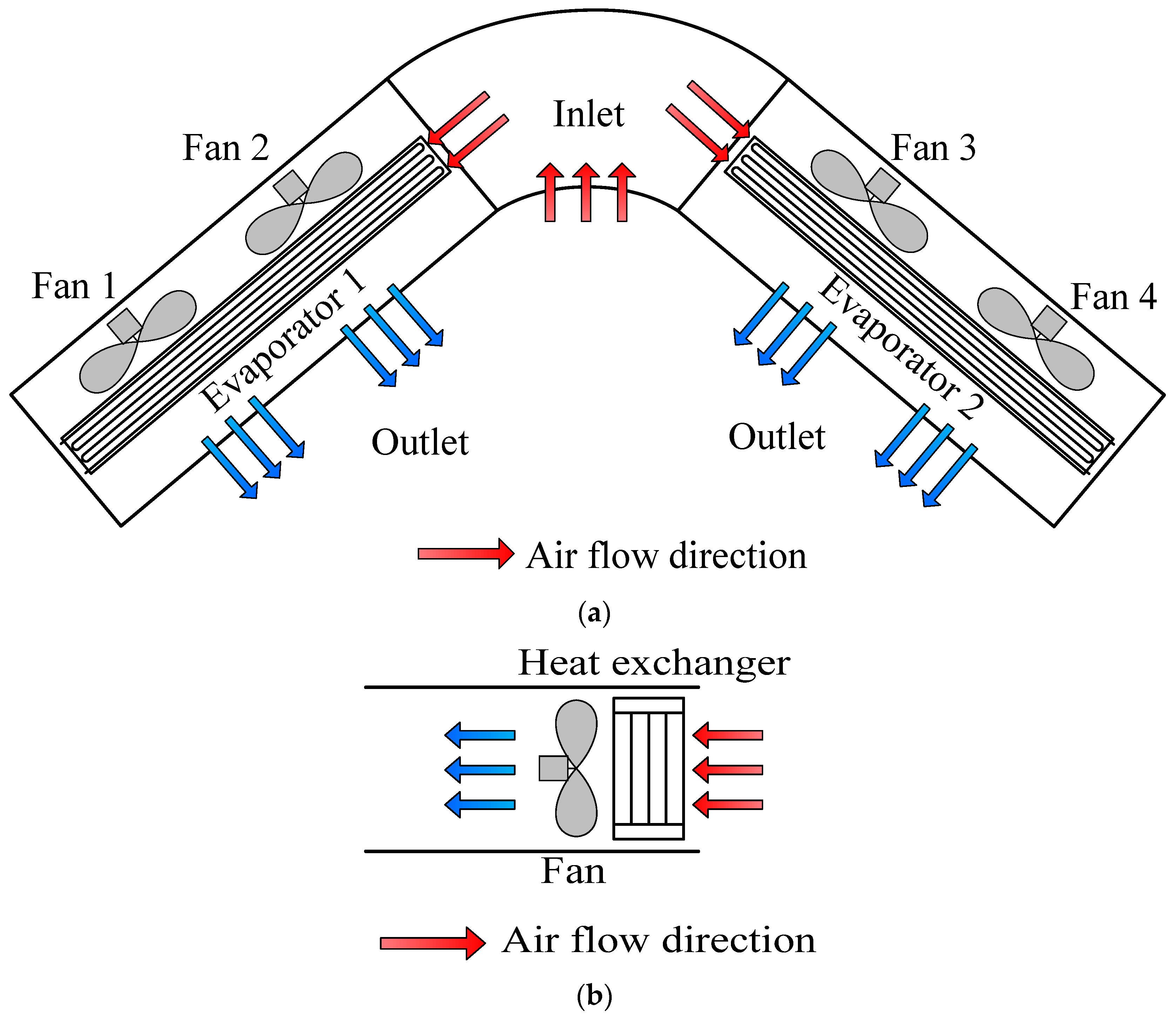
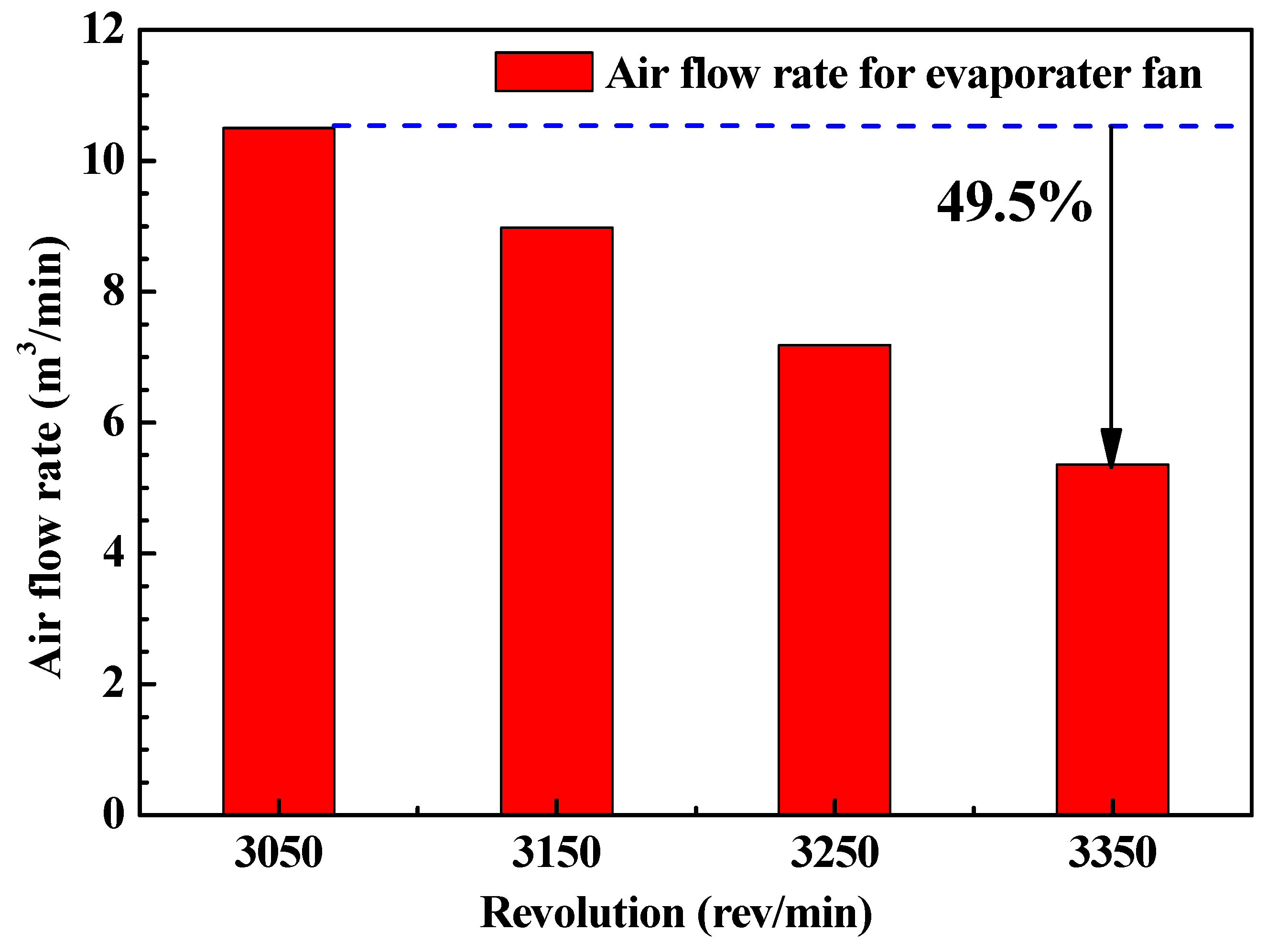
2.4. Air Flow Rate of the Evaporator Fan

Initial air flow rate set of the evaporator fan is very important to satisfy the required cooling capacity of 21.0 kW for the cabin cooling of the special purpose vehicle. An evaporator fan with a rating voltage of 24.0 V was used, along with electric current ranges of 4.3 A to 5.6 A in a radial direction. The fan was a multi-blade type, and the air flow rate was measured with changing fan rotation speeds from 3000 rpm to 3300 rpm with internal rotation of 100 rpm, as shown in Figure 3. Figure 3 shows the air flow rate of the evaporator fan with fan rotation speeds. As the rotation speed of the evaporator fan increased from 3000–3300 rev/min, the air flow rate decreased by approximately 49.5%. The maximum air flow rate of evaporator fan within tested ranges was 10.5 m3/min and the initial air flow rate of the evaporator fan of 10.0 m3/min was set to meet the thermal loads of cabin cooling. The obtained air flow rate of the evaporator fan was used to calculate the air-side cooling capacity of the evaporator part of the air conditioning system.

3. Results and Discussion

The air-conditioning system with two parallel refrigeration cycles for a special purpose vehicle under severe weather and usage conditions was designed, and the cooling performances including the COP and the cooling capacity of the designed system were briefly evaluated. The cooling capacity and the COP needed to satisfy the thermal loads of the cabin room with 12 persons of the tested special purpose vehicle under the warmer weather conditions of Southeast Asia were obtained. Generally, the maximum thermal cooling load of the special purpose vehicle under average weather conditions in the abovementioned region (40 °C outside temperature) was 21.0 kW. As a result, the suggested air conditioning system with two parallel refrigeration cycles for a special purpose vehicle was properly designed to provide the cooling capacity of 21.0 kW.

3.1. Design of the Air conditioning (A/C) with Two Parallel Refrigeration Cycles

By using the refrigerant charge matching method for the cooling system as mentioned in Lee et al. [21], the refrigerant charge of the designed air conditioning system for a special purpose vehicle was set to 1200 g at an outdoor temperature of 40.0 °C and an indoor temperature of 40.0 °C. The compressor speed was set to 2700 rev/min because the cooling speed of the air conditioning system with two parallel refrigeration cycles for the special purpose vehicle at the refrigerant charge amount of 1200 g was superior to other cases, as shown in Figure 4. The indoor temperature of the air conditioning system with the two parallel refrigeration cycle for a special purpose vehicle at the refrigerant charge amount of 1200 g just reached the target temperature 25.0 °C within the elapsed time of 300 s. At the elapsed time of 300 s, the indoor temperatures of the suggested air conditioning system at the refrigerant charge amounts of 1200 g, 1400 g, and 1600 g were 24.7 °C, 25.2 °C, and 26.4 °C, respectively. This cooling time of 300 s for the indoor temperature of 25.0 °C was required for customer satisfaction. In addition, with respect to the time required for the indoor temperatures of the suggested air conditioning system to reach 15.0 °C, the time taken increased by 13.3% when the refrigerant charge amount was decreased from 1600 g to 1200 g. Figure 4 shows the cooling speeds of the air conditioning system with two parallel refrigeration cycles for the special purpose vehicle with the change of refrigerant charge amounts from 1200 g to 1600 g.

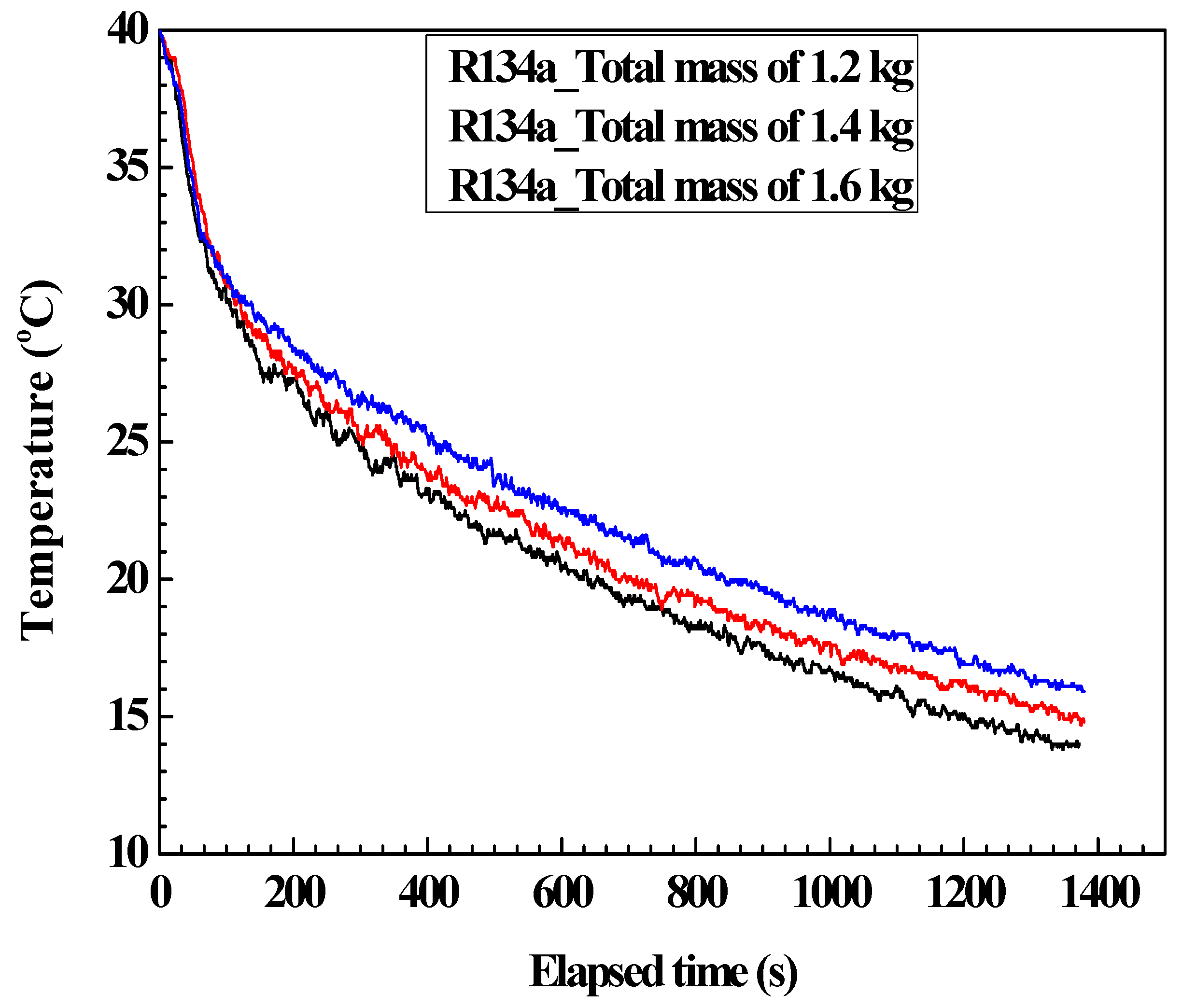
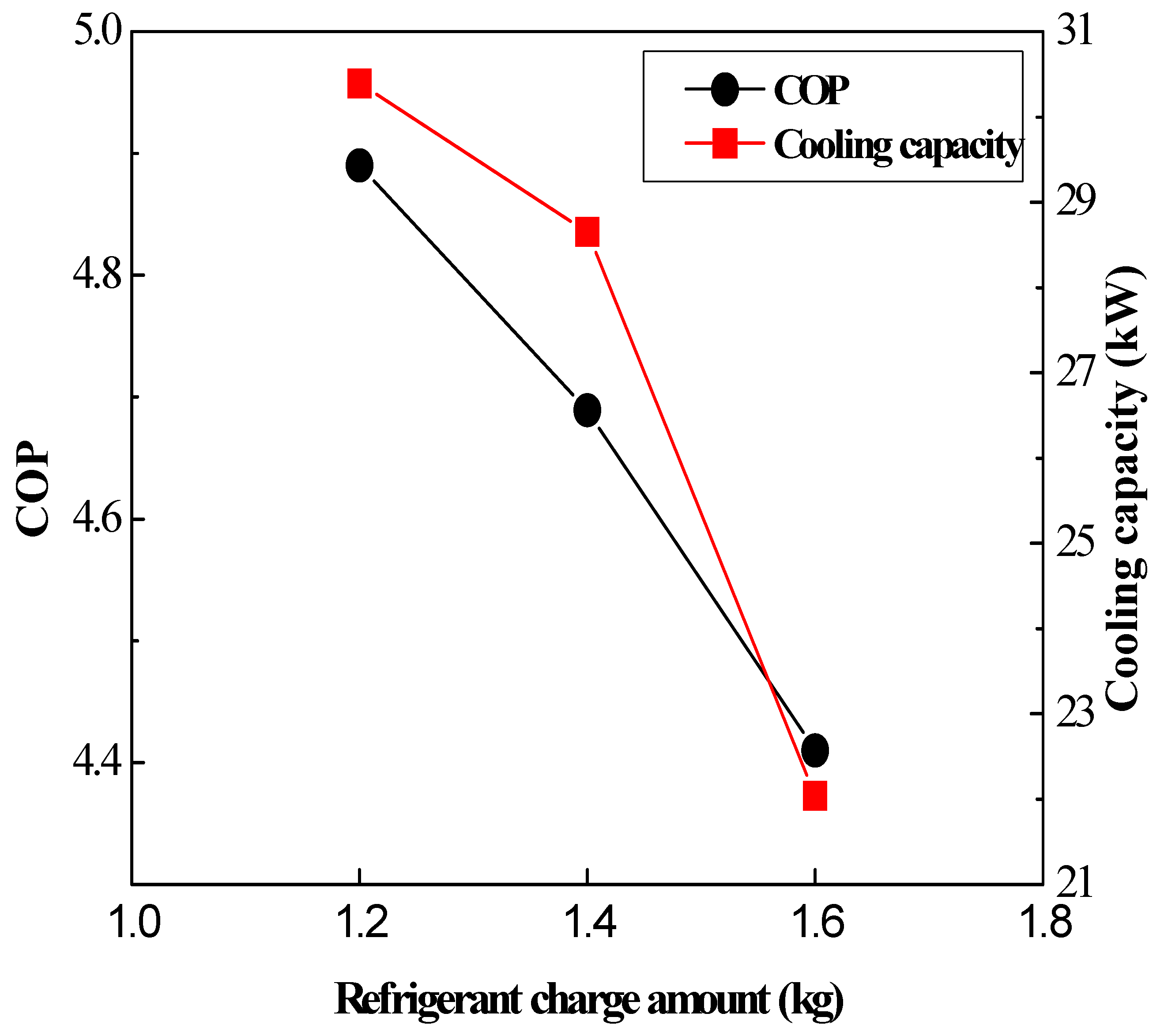
3.2. Cooling Performances (Cooling Capacity and COP) of the Designed A/C

Figure 5 shows the cooling capacity and COP of the air conditioning system with two parallel refrigeration cycles for the special purpose vehicle with the change of refrigerant charge amounts from 1200 g to 1600 g. The cooling capacity and the COP of the suggested air conditioning system increased by 37.9% and 10.9%, respectively, with the decrease of the refrigerant charge amount from 1600 g to 1200 g because of the decreased power consumption of the compressor with the decreased of the refrigerant charge amounts. Based on the results of Figure 4 and Figure 5, the suggested air conditioning system with two parallel refrigeration cycles for the special purpose vehicle was normally operated initially to meet the required cooling capacity of 21.0 kW regardless of the amount of refrigerant, due to the large difference between the refrigerant evaporating temperature and initial inner temperature. However, with respect to the cooling time to be reached at the indoor temperature of 25.0 °C within 300 s and the target indoor temperature of 15.0 °C, the designed air conditioning system with the two parallel refrigeration cycles for a special purpose vehicle was optimized at the refrigerant charge amount of 1200 g and satisfied the requirement of the fast cooling speed for the customers. Therefore, the performance of the designed air conditioning system for a special purpose vehicle showed that it could be used as an air conditioning system for the cabin cooling of a special purpose vehicle used under the warmer weather conditions of Southeast Asia.

4. Conclusions

This study designed the air conditioning system with two parallel refrigeration cycle for a special purpose vehicle and tested the cooling performances of the suggested air conditioning system under extremely hot weather conditions and higher thermal load conditions caused by equipped passengers. An experimental set-up was built to evaluate the cooling capacity and the COP of the designed air conditioning system with two parallel refrigeration cycles using R-134a and parameters were optimized by varying the refrigerant charge amount. In addition, cooling speed of the indoor tempeature to reach the target temperature of 25.0 °C and 15.0 °C, respectively, and was evaluated for suggesting the thermal comfort for passengers with higher thermal loads. The indoor temperature of the air conditioning system with the two parallel refrigeration cycles for a special purpose vehicle at the refrigerant charge amount of 1200 g just reached at the target temperature 25 °C within the elapsed time of 300 s. At the elapsed time of 300 s, the indoor temperatures of the suggested air conditioning system at the refrigerant charge amounts of 1200 g, 1400 g, and 1600 g were 24.7 °C, 25.2 °C, and 26.4 °C, respectively. The cooling time to reach the 15.0 °C inner temperature for the suggested air conditioning system increased by 13.3% with the decrease of the refrigerant charge amount from 1600 g to 1200 g. The cooling capacity and the COP of the suggested air conditioning system increased by 37.9% and 10.9%, respectively, with the decrease of the refrigerant charge amount from 1600 g to 1200 g because of the decreased power consumption of the compressor with the decreased of the refrigerant charge amounts. In addition, the suggested air conditioning system with two parallel refrigeration cycles for the special purpose vehicle was normally operated initially to meet the required cooling capacity of 21.0 kW, regardless of the amount of refrigerant due to the large difference between the refrigerant evaporating temperature and initial inner temperature. The observed cooling performance characteristics of the designed air conditioning system with two parallel refrigeration cycles mean it could be suitable for cabin cooling of the special purpose vehicles. In addition, the cooling speed satisfied the required thermal comfort for passengers with higher thermal loads like combat policemen. In addition, the designed special air conditioning system with two parallel refrigeration cycles for a special purpose vehicle was built to ensure sufficient cooling performance for equipped passengers.

Acknowledgments

This work was supported by the Dong-A University research fund. Some contents of this article were already presented at the 6th International Conference on Experiments/Process/System Modeling/Simulation/Optimization (IC-EpsMsO, Athens-Greece) in 2015.

Author Contributions

Moo-Yeon Lee is the first and the corresponding author. He designed the research and wrote the paper. All results and discussions are performed by Moo-Yeon Lee.

Conflicts of Interest

The authors declare no conflicts of interest.

Nomenclature

A/CAir conditioning
COPCoefficient of performance
CSpecific heat (kJ/kg·K)
hEnthalpy, (kJ/kg)
m ˙ Mass flow rate (kg/s)
Q ˙ Heat transfer rate or cooling capacity, (W)
rpmRevolution per minute (rev/min)
TTemperature, (°C)
V ˙ Volume flow rate, (m3/s)
WWork, (kJ/kg)
ρ Density (kg/m3)

Subscripts

airair
Comp.compressor
Evap.evaporator
In.inlet
Out.outlet
Ref.refrigerant

References

  1. Lee, M.Y.; Lee, D.Y. Review on Conventional Air Conditioning, Alternative Refrigerants and CO2 Heat Pumps for Vehicles. Adv. Mech. Eng. 2013, 5, 713924. [Google Scholar] [CrossRef]
  2. Lee, H.S.; Lee, M.-Y. Cooling Performance Characteristics on Mobile Air-Conditioning System for Hybrid Electric Vehicles. Adv. Mech. Eng. 2013, 5, 282313. [Google Scholar] [CrossRef]
  3. Lee, D.W.; Jeong, H.H.; An, J.C.; Baek, C.H.; Kim, J.H.; Jeong, C.S.; Wang, Y.H. Experimental Study of Impact on the Thermal Comfort for Three-dimensional Air-Conditioning System. In Proceedings of the KSAE 2013 Annual Conference, Jeju, Korea, 1–4 May 2013; pp. 706–711.
  4. Yoon, S.H.; Park, J.Y.; Son, D.Y.; Choi, Y.H.; Park, K.S. A Numerical Study of Automotive Indoor Thermal Comfort Model According to Boarding Conditions and Parameters Related to HVAC. Trans. Korean Soc. Mech. Eng. A 2014, 38, 979–988. [Google Scholar] [CrossRef]
  5. Seo, J.W.; Park, J.H.; Choi, Y.H. Evaluation of Thermal Comfort and Cooldown performance inside Automotive Cabin according to Air-conditioning Vent Location. Trans. Korean Soc. Autom. Eng. 2012, 20, 120–129. [Google Scholar] [CrossRef]
  6. Kim, J.H.; Kim, J.K.; Kim, S.B.; Ha, O.N. An Experimental Study on Performance Characteristics of Refrigeration System Using R134a Refrigerating System. In Proceedings of the KSME 2007 Annual Spring Conference, Busan, Korea, 30 May–1 June 2007; pp. 1529–1534.
  7. Jang, J.K.; Chang, Y.S.; Kang, B.H. Performance Analysis of Evaporator with Improved Distribution in Plate Heat Exchanger using R134A. In Proceedings of the KSME Thermal Engineering 2012 Annual Spring Conference, Gangwon-do, Korea, 23–26 May 2012; pp. 9–10.
  8. Sin, Y.C.; Kim, S.H.; Cho, H.H. Analysis of Cooling Performance in a R404A and R134a Refrigerator Truck. In Proceedings of the KSAE 2012 Annual Conference, Goyang, Korea, 21–24 November 2012; pp. 1037–1042.
  9. Tamura, T.; Yakumaru, Y.; Nishiwaki, F. Experimental study on automotive cooling and heating air conditioning system using CO2 as a refrigerant. Int. J. Refrig. 2005, 28, 1302–1307. [Google Scholar] [CrossRef]
  10. Tuo, H.; Hrnjak, P. Flash gas bypass in mobile air conditioning system with R134a. Int. J. Refrig. 2012, 35, 1869–1877. [Google Scholar] [CrossRef]
  11. Qi, Z.; Zhao, Y.; Chen, J. Performance enhancement study of mobile air conditioning system using microchannel heat exchangers. Int. J. Refrig. 2010, 33, 301–312. [Google Scholar] [CrossRef]
  12. Lee, Y.; Jung, D. A brief performance comparison of R1234yf and R134a in a bench tester for automobile applications. Appl. Therm. Eng. 2012, 35, 240–242. [Google Scholar] [CrossRef]
  13. Zindove, T.; Niekerk, T.V.; Wilm, T.; Mercorelli, P. Development of a temperature controlled weathering test box to evaluate the life cycle behaviour of interior automotive components. IFAC-PapersOnLine 2015, 48, 117–120. [Google Scholar] [CrossRef]
  14. Incropera, F.P.; DeWitt, D.P. Fundamentals of Heat and Mass Transfer, 4th ed.; John Wiley & Sons: New York, NY, USA, 1996. [Google Scholar]
  15. Moffat, R.J. Uncertainty analysis in the planning of an experiment. J. Fluids Eng. 1985, 107, 173–178. [Google Scholar] [CrossRef]
  16. Methods of Testing for Seasonal Efficiency of Unitary Air-Conditioners and Heat Pumps; ASHRAE Standard 116; American Society of Heating, Refrigerating and Air-Conditioning Engineers (ASHRAE): Atlanta, GA, USA, 1983.
  17. Kim, S.C.; Won, J.P.; Kim, M.S. Effects of operating parameters on the performance of a CO2 air conditioning system for vehicles. Appl. Therm. Eng. 2009, 29, 2408–2416. [Google Scholar] [CrossRef]
  18. Choi, E.S.; Park, I.G. Effects of charged mass of refrigerant on the performance of a home air-conditioner. In Proceedings of the SAREK 1998 Winter Annual Conference, Gangwon-do, Korea, 11–14 November 1998; pp. 204–208.
  19. Seo, J.H.; Bang, Y.M.; Lee, M.Y. Investigation on the performance of special purpose automotive air conditioning system using dual refrigeration cycle. Trans. Korean Soc. Mech. Eng. B. 2016, 40, 213–220. [Google Scholar] [CrossRef]
  20. Howell, R.H.; Coad, W.J.; Sauer, H.J. Principles of Heating Ventilating and Air Conditioning, 6th ed.; ASHRAE: Atlanta, GA, USA, 2009. [Google Scholar]
  21. Lee, M.Y.; Lee, D.Y.; Kim, Y.C. Performance characteristics of a small capacity directly cooled refrigerator using R290/R600a. Int. J. Refrig. 2008, 31, 734–741. [Google Scholar] [CrossRef]
Figure 1. Schematic diagram of the experimental setup.
Applsci 07 00190 g001
Figure 2. Schematic diagrams of the evaporator and condenser parts. (a) One section of the evaporator part; (b) Condenser part.
Applsci 07 00190 g002
Figure 3. Air flow rate of the evaporator fan with fan rotation speeds.
Applsci 07 00190 g003
Figure 4. Cooling speeds of the two parallel refrigeration cycles with the refrigerant charge amount for a special purpose vehicle.
Applsci 07 00190 g004
Figure 5. Cooling capacity and COP of the two parallel refrigeration cycles with the refrigerant charge amount for a special purpose vehicle.
Applsci 07 00190 g005
Table 1. Specifications of the air conditioning system with two parallel refrigeration cycles.
Components Specifications
CompressorDisplacement rate (cm3/rev)
Type
Size (L, W, H, mm)
160.0
Reciprocating
1100.0 × 920.0 × 220.0
EvaporatorFin type
Size (L, W, H, mm)
Fan type
Fin type
Aluminum plate
850.0 × 160.0 × 163.0
Multi-blade
Aluminum groove
CondenserSize (L, W, H, mm)
Fan type
820.0 × 52.0 × 270.0
Axial and propeller
Receiver tankSize (D, H, mm)120.0 × 320.0
AccumulatorSize (D, H, mm)120.0 × 180.0
Expansion deviceTypeThermostatic expansion valve (TEV)
RefrigerantTypeR-134a
Table 2. Test conditions. rpm: revolutions per minute.
ComponentsConditions
Outdoor air temperature (°C)40.0
Indoor air temperature (°C)25.0
Indoor target temperature (°C)15.0, 25.0
Refrigerant charge amount (g)1200, 1400, 1600
Compressor speed (rpm)2700
Table 3. Average outdoor temperature of the Southeast Asian region.
RegionsTemperature (°C)
Vietnam34.3
Thailand38.4
Myanmar38.4
India41.9
Saudi Arabia43.2
Yemen43.1
Average temperature40.0
Table 4. Uncertainties of the experimental parameters and measured data. COP: coefficient of performance.
ComponentsConditions
Thermocouples (T-type)±0.1 °C
Pressure gage (Sensors, PI3H)±0.1%, Max 25 MPa
Mass flow rate (Coriolis type)±0.2%, Max 650 kg/h
Data logger (E. Gate IP (V3), 2.93 W @ 12.06 V)±0.5%
COP4.7%
Cooling capacity3.5%
Table 5. Thermal loads for the required air conditioning system design.
ComponentsConditions
Inner volume (m3)17.1
Constant of the wallMetal, polyurethane, wood
Maximum number of passengers 12
Amount of body heat (W)750

