
Pushover Analysis on Infill Effects on the Failure Pattern of Reinforced Concrete Frames

School of Civil Engineering, Qingdao University of Technology, Qingdao 266033, China
*
Author to whom correspondence should be addressed.
Appl. Sci. 2017, 7(4), 428; https://0-doi-org.brum.beds.ac.uk/10.3390/app7040428
Submission received: 27 March 2017
/
Revised: 12 April 2017
/
Accepted: 20 April 2017
/
Published: 23 April 2017
Abstract
:This paper presents a pushover analysis using ABAQUS (Dassault Company, Providence, Rhodes Island, USA) for spatial reinforced concrete (RC) frames. The main purpose is to study the effect of the infills on failure patterns of the RC frames. The Finite Element Method (FEM) model considered an RC frame with fulfilled infills, half-filled infills, and without infills. Column moment, the effective width of the cast in situ slab, and the required ratio of column to beam strength are calculated and analyzed. Research findings indicate that the location of the inflection point varied because of the effect of infills. Some of the calculated values of column moments are larger than those values according to the design code. The effective slab width and the required ratio of column to beam strength are found to be reduced due to the infill effects. The actual effective width of the slab should be considered in the required ratio of column to beam strength. Reasonable advice is proposed and discussed for design purposes.
1. Introduction
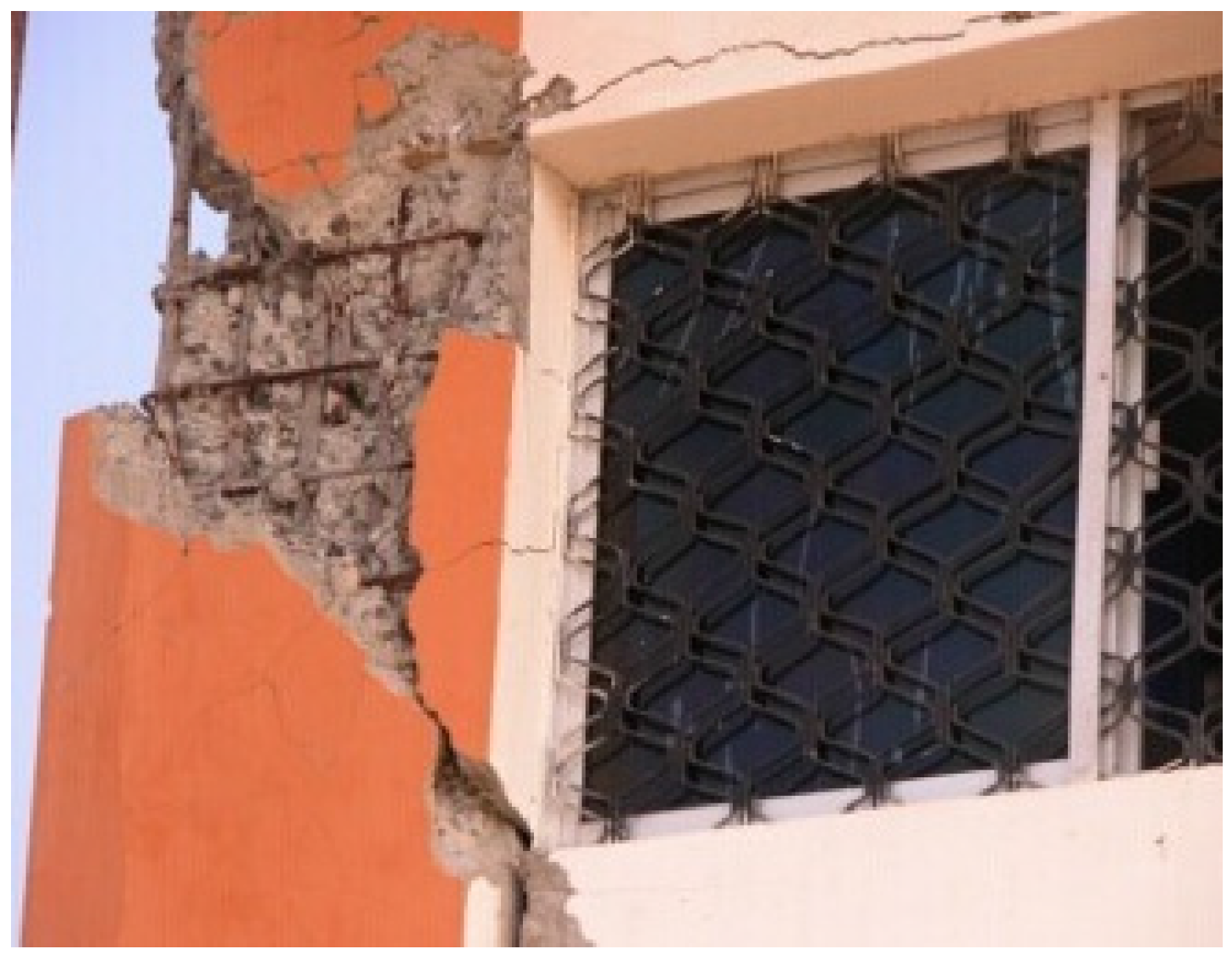
Worldwide, seismically-induced structural damage demonstrates that “strong column-weak beam” ductile failure mechanisms have not been fully, or even partially, realized, which is inherently contradictory with the philosophy that has been adopted by design codes [1,2,3,4,5,6]. Seismic damage investigation [7,8] and relevant studies revealed that such mechanical behaviors should have been substantially changed due to the interactions between infills and surrounding frames. Improper openings and half-filled infills resulted in short columns, which betray the so called “strong shear, weak bending” principles [9,10,11,12], as shown in Figure 1 and Figure 2.
EC8 [13] and ASCE 41-06 [14] point out that diagonal strut force of infills are applied. Chinese code [15] specifies that infills can be considered as non-structural components. Only a reduced period factor is introduced to consider the infills’ effect on the dynamics of the structures. This method simplifies the design process, but ignores the infills’ effect on the seismic performance of structural components and what shall be passed on to the whole structure. Neglecting the interactions between the infills and the surrounding frames will lead to discrepancy. How to evaluate the internal force of reinforced concrete (RC) components correctly and propose appropriate recommendations become challenging issues.
During recent decades, studies of frames with infills have been carried out. In the 1960s, Holmes [16] and Smith [17] proposed that the carry capacity and stiffness of frames could be increased due to infills. Zovkic [11] and Bertero [18] studied infill material effects on the seismic performance of structures and pointed out that the performance of the infill was of great relevance to material strength. Mehrabi [19] stated that a strong infill weak frame had better hysteretic energy dissipation capacity. However, existing studies showed that a weaker floor is another important reason for non-ductile failure [20]. Low frequency cyclic loading experiments were carried out by Stavridis [21] and Sigmund [22] to research infills with openings. Tests results indicated that the hysteretic energy dissipation capacity was decreased due to openings, and the failure mode of infills was related to the height and location of the openings.
The above studies focused mainly on the effect of infills by subassemblies. However, only a few studies have been carried out in RC frames structures. The joint effect of cast in-situ slabs and infills are still insufficient. To guarantee accurate and safe design of RC frames with infills, this paper carries out a pushover analysis using ABAQUS (Dassault Company, Providence, Rhodes Island, USA) and focuses on the internal forces, such as the bending moment at the ends of columns, the effective slab width affected by infills, and the required ratio of column-to-beam strength. Recommendations are proposed based on the analysis results.
2. Numerical Modeling
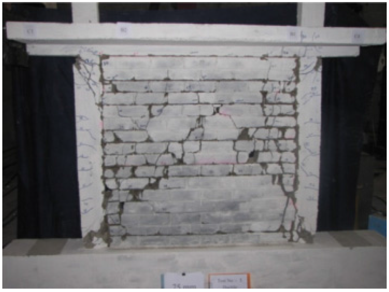
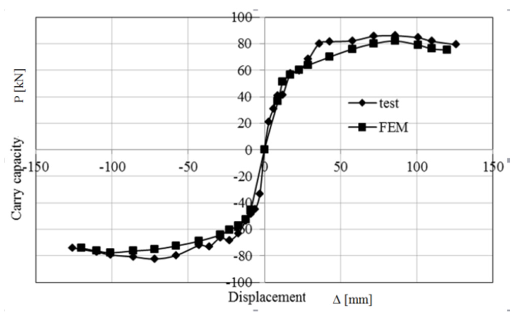
Three-dimensional validation models have been developed using ABAQUS (Dassault Company, Providence, Rhodes Island, USA). A damaged plasticity model is applied to simulate the cracking behavior of the concrete. Concrete and reinforcement element types are C3D8R and T3D2, respectively. Reinforcement is embedded into the concrete in the model. The main element size is 50 mm. The loading program is low frequency cyclic loading and the loading path can be found in [23]. The displacement of the test is from 0.1% story drift to 4.2% story drift. The loading increment follows ±3 mm (0.1%), ±6 mm (0.2%), ±9 mm (0.3%), ±12 mm (0.4%), ±17 mm (0.6%), ±23 mm (0.8%), ±29 mm (1%), ±36 mm (1.25%), ±43 mm (1.5%), ±58 mm (2%), ±72 mm (2.5%), ±86 mm (3%), ±101 mm (3.5%), ±110 mm (4%), and ±120 mm (4.2%). The full Newton Raphson solution technique is used in the analysis. The unbalanced force convergence criterion and the displacement criterion are used in the simulation. The convergence standard of the unbalanced force is 5 × 10⁻⁴. The comparison of the skeleton curves of RC-2 in [23] is shown in Figure 3. The comparison characteristic displacement and load are summarized in Table 1. The analysis results show that the Finite Element Analysis (FEA) data fit the experimental results well and can be used to conduct parametric analyses.
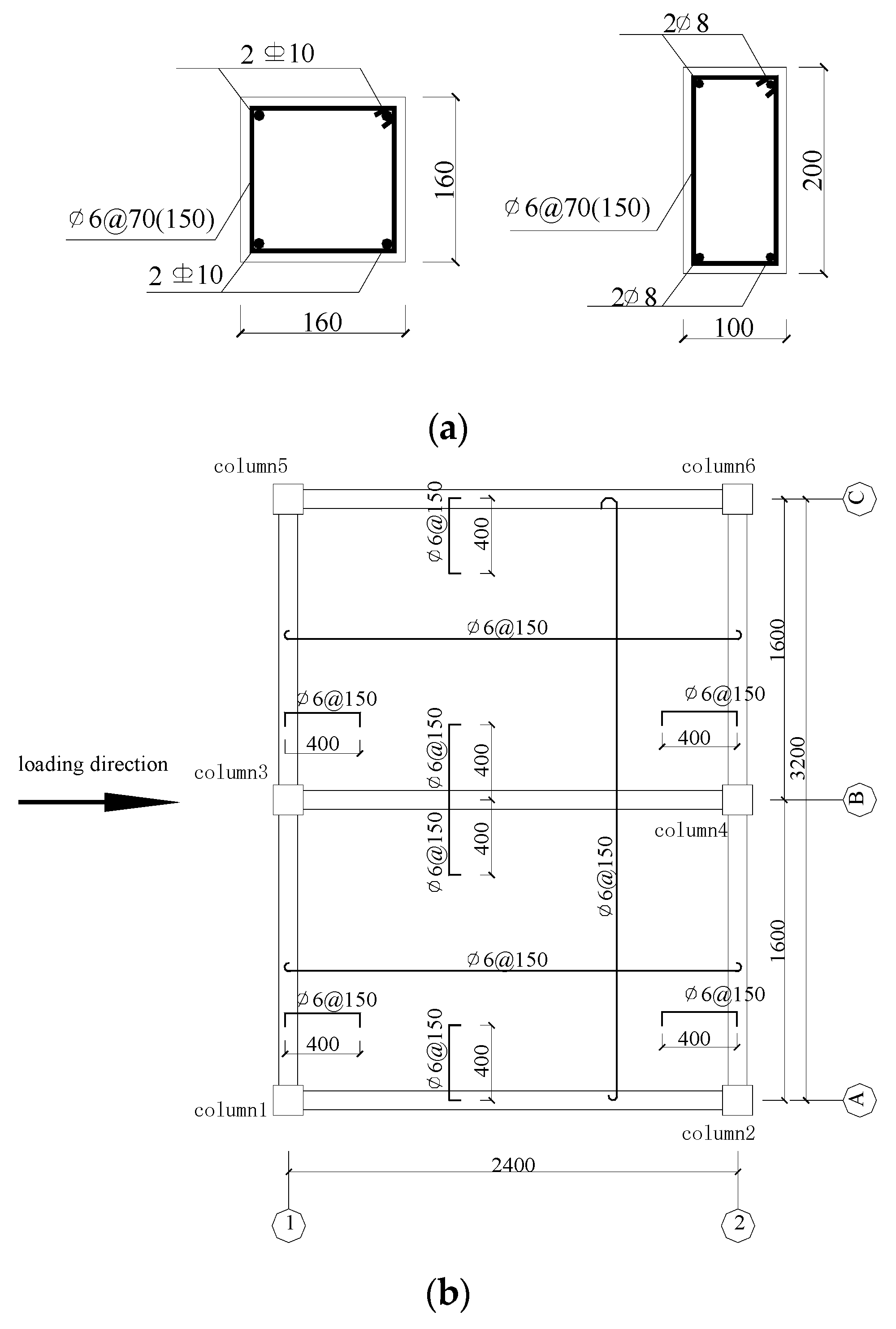
The pushover model is extended based on the experiment frame RC-2 and is also scaled 1:2.5. The model is 1 bay × 2 bay with one story. The plan dimension is 2.4 m × 3.2 m. The height of the model is 1.44 m. The cross-section dimension of the column and beam are 160 mm × 160 mm and 100 mm × 200 mm, respectively. The thickness of the slab is 50 mm. Constitutive equations of steel and concrete are shown in Equations (1)–(9) [24].
Constitutive equations of steel:
where Es = the elastic modulus of the steel bar; = stress of the steel bar; = the representative yield strength of the steel bar; = the yield strain corresponding to ; = the strain at the starting point of hardening; = the peak strain; and k = the slop of the hardening section.
Constitutive equations of concrete:
The stress-strain curve under axial compression:
where = parameter for declining segments in the stress-strain curve under axial compression; = the representative strength of the concrete axis compression strength; = peak strain corresponding to ; and = parameter of damage evolution for concrete axis compression strength.
The stress-strain curve under axial tension:
where = parameter for the declining segments in the stress-strain curve under axial tension; = representative strength of the concrete axis tensile strength; = peak strain corresponding to; and = parameter of damage evolution for the concrete axis tensile strength.
The axial compressive ratio of edge and corner columns are 0.6 and 0.3, respectively. Details of the components are shown in Figure 4.
Fired bricks are used in the pushover model, and the constitutive relation of the material is shown in Equation (10) [25].
According to [23], the compressive strength of concrete was fc = 28.4 MPa and the elastic modulus was 2.85 × 10⁴ MPa for the RC frames. The steel bar yield strength of diameter 6, 8, and 10 are 294 MPa, 304 MPa, and 384 MPa, respectively. The steel bar yield elastic moduli of diameters 6, 8, and 10 are 1.51 × 10⁵ MPa, 1.68 × 10⁵ MPa, and 1.56 × 10⁵ MPa, respectively. The compressive strength of infill is 2.67 MPa and the elastic modulus is 4272 MPa.
A surface-to-surface contact algorithm is applied to simulate the interface behavior between infills and the surrounding frames. A penalty function was used for tangential friction and the friction coefficient is 0.7. Hard contact is adopted in the normal behavior. Axes A, B, and C designate the frames with a half-filled infill wall, non-infill wall, and full-filled infill wall, respectively. The FEM model is shown in Figure 5.
3. Results and Discussions
3.1. Damage Phenomenon of the Models
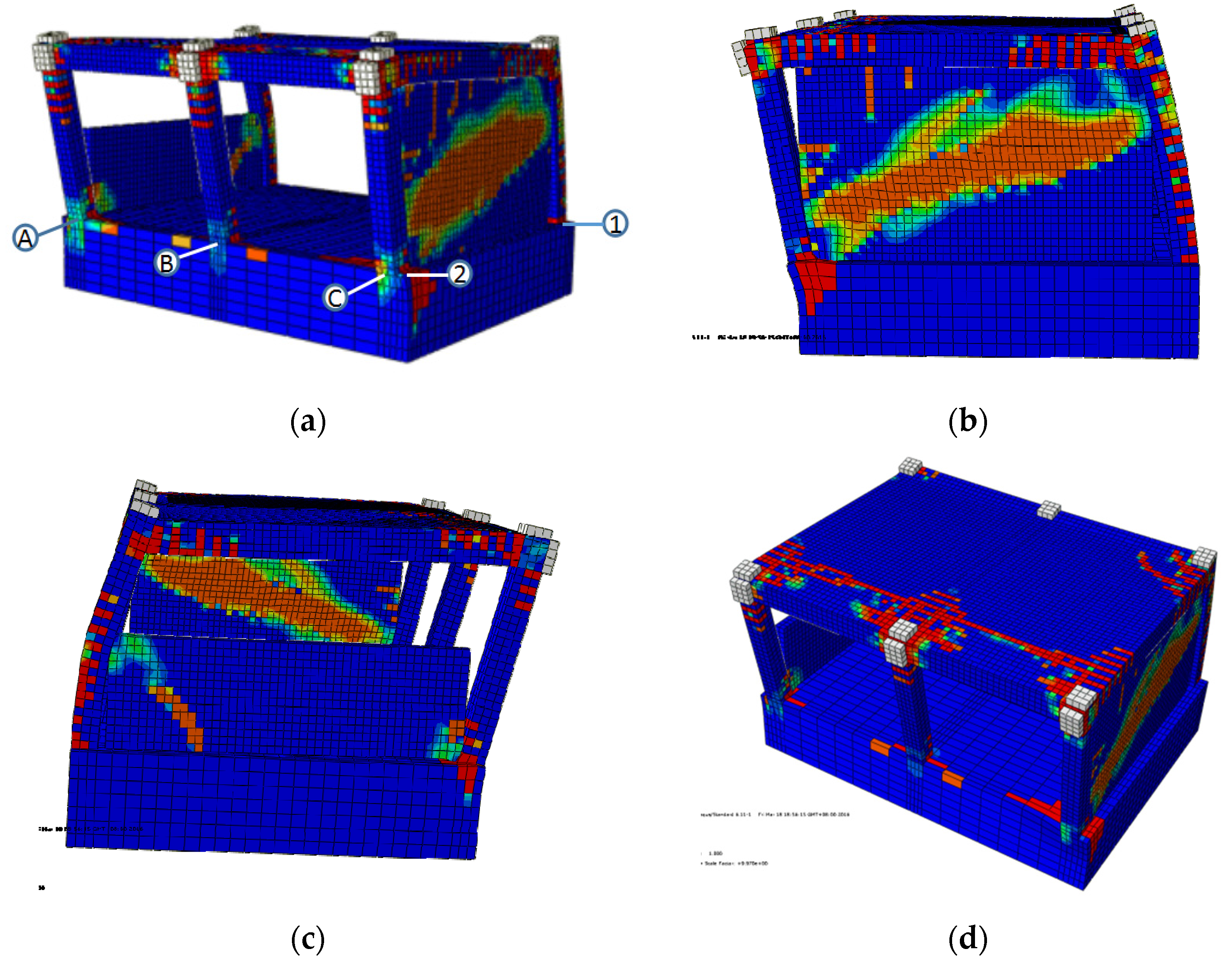
The frame damage cloud chart in tension is shown in Figure 6. The cracks in columns with infills are shown to be focused not only on the ends of the columns, but also within a certain length around those ends, such as those shown in column 1 and column 5. The damage of beams along axis C is shown to be more severe than that along the axis A. Such phenomena can be attributed to the participation of infills. According to the ASCE 41-06 [14], when cracks occurred in the infills, the mechanism of infills can be considered as struts. Therefore, infills should have substantially changed the mechanism of columns and beams. The computational model of half-filled infills has not been considered in [14], but in FEM analysis the trend of cracks from the half-filled infill wall in axis A indicates that the strut may not be distributed and developed along the diagonal direction of the infill wall. Therefore, an appropriate computational model must be investigated and developed.
3.2. Shear Force of Columns
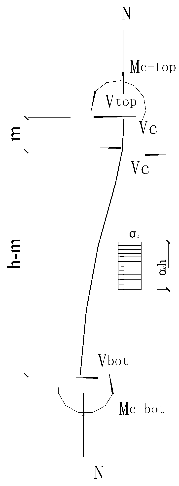
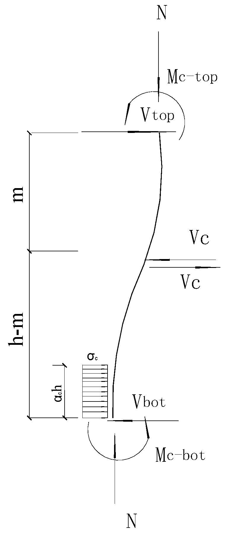
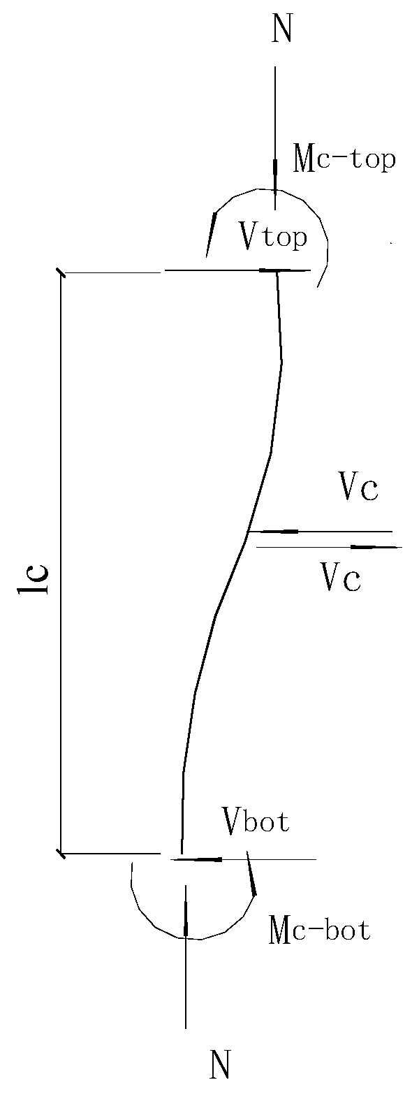
The strut effect of infilled walls should be taken into account in the calculation of column shear force. The stress between the frame and the infilled wall is simplified as a rectangular shape. The contact length is equal to , where is the equivalent contact length factor and h is the net height of the column, and can be calculated by Equations (13)–(16). The computing model of column 5 is shown in Figure 7. Suppose the second-order effect of the column is ignored, the equations are shown in Equations (11) and (12).
where, and = the bend moments of top column and bottom column, respectively; t = the thickness of the infilled wall; and = the shear forces of top column and bottom column, respectively; Vc = shear force at the inflection point; m = the distance between the column top and the location of the inflection point of the column; and = the equivalent stress of the infilled wall, and can be calculated by [26].
In the case of the column with the half-filled wall, the strut acts on the middle part of the column. The computing model of Column 1 is shown in Figure 8. The equations are shown in Equations (13) and (14). The second-order effect of column is also ignored.
where, a = the height of the infilled wall.
The computing model of Column 2 and Column 6 is shown in Figure 9. The equations are shown in Equations (15) and (16).
Shear force of each columns calculated by Equations (11)–(16) are shown in Table 2. It can be seen that the results of the columns with infilled walls have large deviations compared to Chinese code [15], EC8 [13], and ASCE41-06 [14]. Chinese code [15] and ACI [27] code do not take infilled walls into consideration, and the computing model is shown in Figure 10. EC8 provision 5.9 defines the clear column length equal to the length of column not in contact with the infills, considering the height of the infills is smaller than the clear length of the adjacent column. ASCE provision 7.4.2 points out that the reduced column length should be taken into consideration. The values are 1.56 to 5.02 times larger than those calculated by the codes. Shear failure of the column may appear in frames with infilled walls and shall be considered in the design process.
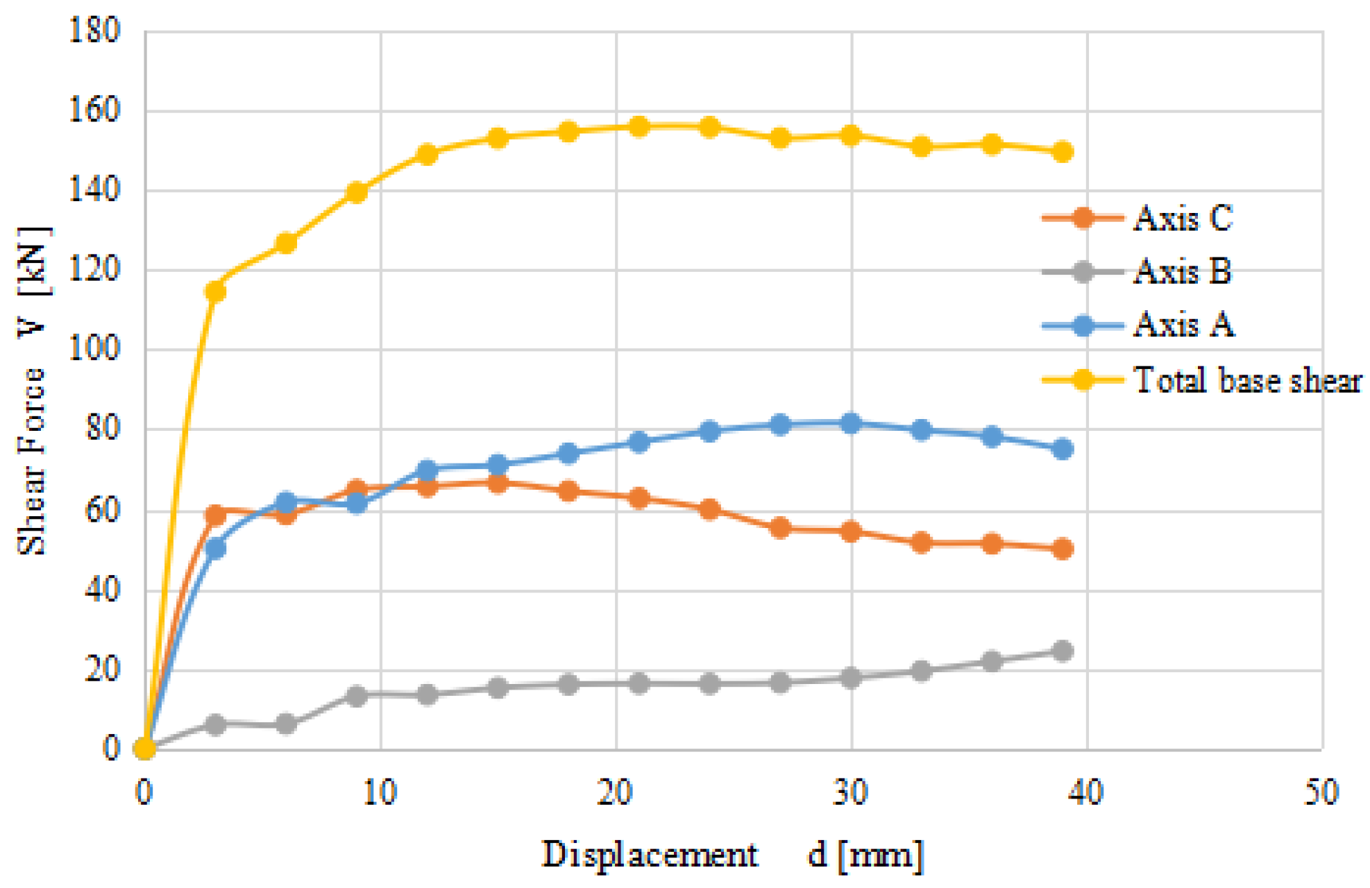
3.3. Base Shear Distribution of Each Axis Frame
The base shear of each axis frame is shown in Figure 11. It can be indicated that during the loading process the base shear distribution appeared among the three axis frames. At a displacement of 3 mm, the maximum base shear appeared in the axis C frame, while the minimum base shear appeared in the axis B frame. Due to the damage of the full-filled walls, the shear of axis C decreased while the shear of axis A increased when the displacement was larger than 12 mm. The shear of axis A began to decrease after 30 mm, which indicated that the half-filled wall was damaged. The shear force shifted to the axis B frame and the base shear of the axis B frame increases. The base shear of axes A and C are significantly greater than axis B at 39 mm, which illustrated that the infilled wall plays an important role in the whole lateral stiffness of the structure.
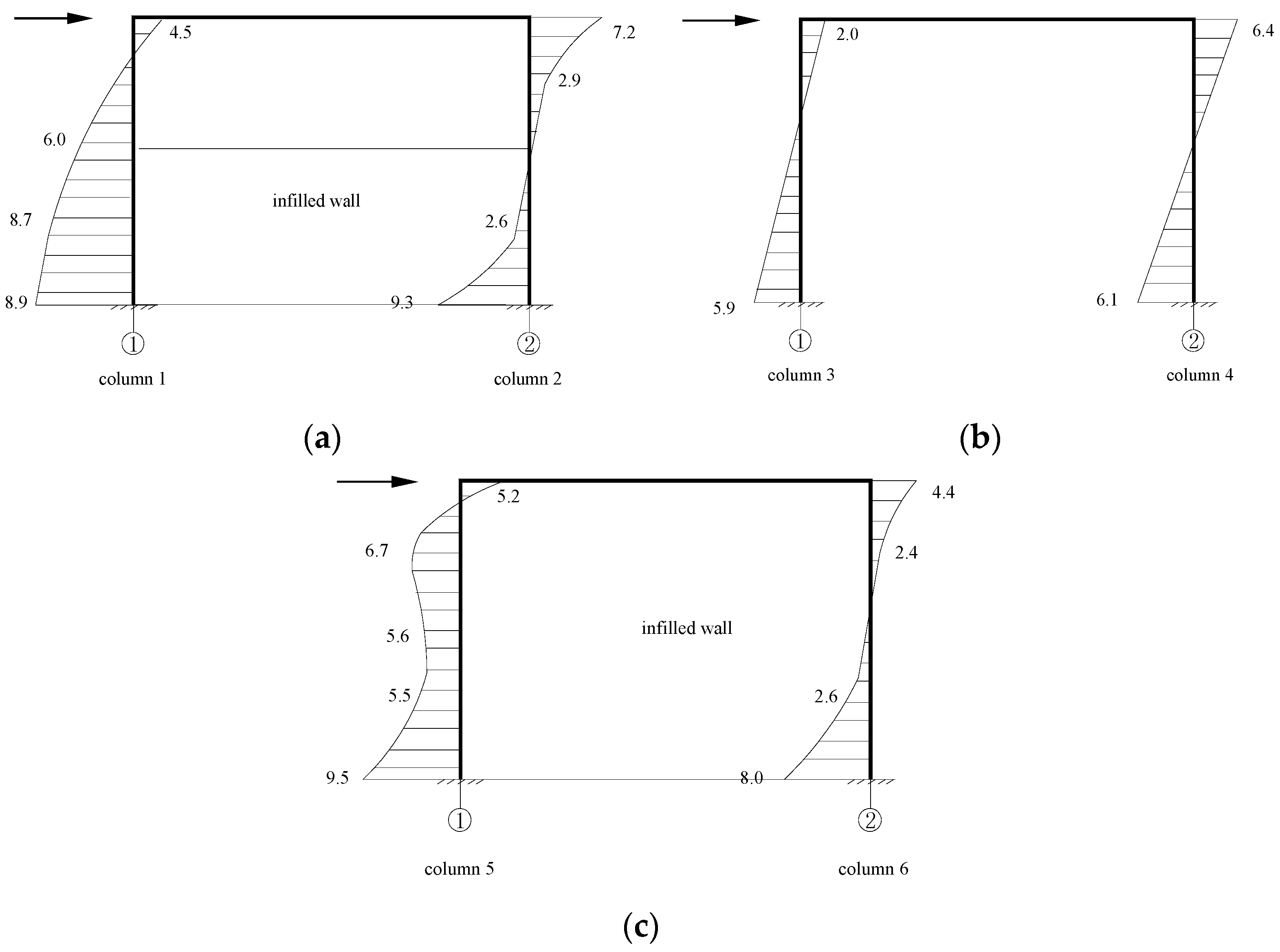
3.4. Bending Moments of Columns
According to the Chinese code [15], 2% story drift can be defined as strong earthquakes. Thus, the bending moments of columns are calculated at 2% story drift and are compared in Figure 12. Figure 12 shows that the infills affect the bending moment of columns significantly, especially for the half-infilled and full-filled frames. The height of the inflection point within the column moved to 0.89 h (Column 5 of axis C) and 0.85 h (Column 1 of axis A) from the column feet borders, respectively. In the inflection point method, the inflection point is at 2/3 h from the column feet for the 1st floor columns (where H is the clear height of the column). Table 3 summarizes the comparison between calculation results by codes and FEM analysis. The values of the column moments are calculated by the inflection point method. Some FEM analysis results indicate that by considering the actual infill contribution, the bending moments could be 6.1%–30.9% larger than those according to the design codes. It could be dangerous, according to the standard design approach. Therefore, infills should be paid sufficient attention in seismic design.
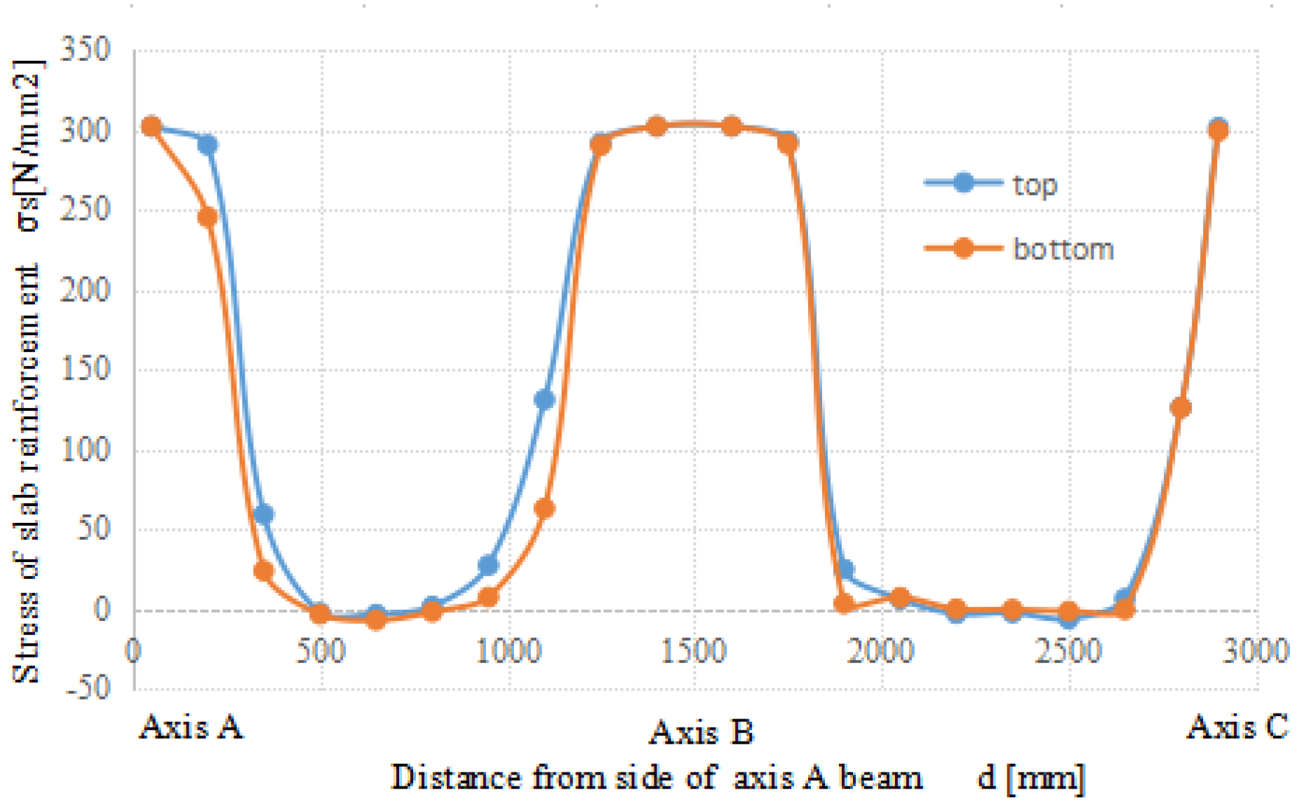
3.5. Effective Slab Width
Stress of the top and bottom slab reinforcement is shown in Figure 13. Figure 13 indicates that the rebar near the beams yielded at 2% story drift. Stress of the top reinforcement is slightly larger than that of the bottom reinforcement. A comparison between axis A and axis C indicates that infill affects the stress of the slab reinforcement. The participation of slab reinforcement on two sides of the beam of axis B is larger than those of axes A and C. Meanwhile, participation of slab reinforcement on two sides of the beam of axis A is larger than those of axis C. It can be concluded that role of the slab is weakened by infills and the effective slab width should be adjusted according to the infill types.
The expression for the effective slab width () is defined in Equation (17), where the equivalent strain method is used [23]:
The calculated results of each axis are summarized in Table 4. The effective slab width decreases significantly due to infills, and values according to the ACI code [27] and other researchers [28,29] are on the conservative side, especially in the full-filled infill case. According to the FEM results, effective slab width should be equal to b + 4t for interior joints and b + 2t for exterior joints with full-filled infills. The effective slab width should be equal to b + 6t for interior joints and b + 3t for exterior joints with half-filled infills (where t is the thickness of the slab). The effective slab width of axis B is larger than the ACI code and existing research results, which means it might be unsafe during the design process.
3.6. Required Ratio of Column to Beam Strength
The required ratio of column to beam strength is defined in Equation (18). The calculated results of each joint are shown in Table 5.
where = sum of moment of columns calculated at the 2% story drift; and = sum of moment of beams calculated at the 2% story drift. Where the slab is in tension under moments at the face of the joint, slab reinforcement within an effective slab width can be calculated with the proposed equations above.
It can be seen that the required ratio of column to beam strength is smaller than 1.0 with full-filled infill, which demonstrated that the infilled wall has changed the behavior of the frame. The required ratio considered slab is 16–70% larger those ignored slab. In other words, the required ratios of Joint 2 of axis A and Joint 4 of axis B, when the slab is ignored, are 1.48 and 1.28 , respectively. When the slab is taken into consideration, the values change to 1.13 and 0.76, respectively. Thus, if the effective width is ignored, the amplified factor in the column may still not be enough to achieve a “strong column weak beam”. The effective slab width should take infills into consideration and the effective width should take the infill type into account.
4. Conclusions
Based on the pushover analyses, the following conclusions are made:
- (1)
- The columns’ shear forces calculated by FEM results are 1.56 to 5.02 times larger than those calculated by design codes. Shear failure of a column may appear in frames with infilled walls. This shall be considered in the design of the column.
- (2)
- Infilled walls exhibit a significant effect on column bending moments, however, this has not been sufficiently addressed in the current design code and practice. According to the FEM analysis, bending moments of some columns are shown to be 6.1%–30.9% larger than those obtained from the design codes. It will be inherently unsafe according to the standard design approach. The influence of infills on the location of the inflection point should be taken into account when using the inflection point method.
- (3)
- Amplified factors of the sum of column bending moments are normally used for the purpose of achieving a “strong column weak beam” design philosophy. However, most of the available design codes neglect the role of cast in situ slabs. Analysis results show that the effective slab width will be particularly reduced by the existence of infills. Combined action of slabs and infills should be taken into account in the design. According to the FEM results of the current model, the effective slab width is recommended to be equal to b + 4t for interior joints and b + 2t for exterior joints with fulfilled infills, whereas the effective slab width is recommended to be equal to b + 6t for interior joints and b + 3t for exterior joints with half-filled infills, respectively.
- (4)
- The required ratio of column to beam strength is reduced when infill exists, i.e., particularly the full-filled case, which indicates that the infilled wall has changed the behavior of the frame substantially. If the effective width is considered, the columns could become “stronger” than presumed.
Owing to some limitations, the above analysis demonstrated only partial parameters’ effects on the behavior of reinforced concrete frames, with or without infills, in the context of structural seismic design, particularly relevant to “strong column weak beam” philosophy. More parameters, such as different material models and properties, openings, and axial load ratios, etc., shall be taken into consideration in further investigations to present a comprehensive understanding of the gaps between the current design standard and the practice.
Acknowledgments
The research is financially supported by the National Natural Science Foundation of China (Grant No. 51508289, 51478231, and 51608288) and the Taishan Scholar Priority Discipline Talent Group program funded by the Shandong Province.
Author Contributions
Ning Ning carried out the simulation and analyzed the FEA results. Chunwei Zhang, Dehu Yu and Shan Jiang gave suggestions on establishment of finite element model and theoretical calculation of the paper.
Conflicts of Interest
The authors declare no conflict of interest.
References
- Arslan, M.H.; Korkmaz, H.H. What is to be learned from damage and failure of reinforced concrete structures during recent earthquake in Turkey? Eng. Fail. Anal. 2007, 14, 1–22. [Google Scholar] [CrossRef]
- Yan, B.; Huang, L.; Deng, L. Approach of the collapses of RC frame structure school buildings. In Proceedings of the Earth and Space 2010: Engineering, Science, Construction, and Operations in Challenging Environments (2010 ASCE), Honolulu, HI, USA, 14–17 March; 2010; pp. 2653–2662. [Google Scholar]
- Rossetto, T.; Peiris, N. Observations of damage due to the Kashmir earthquake of October 8, 2005 and study of current seismic provisions for buildings in Pakistan. Bull. Earthq. Eng. 2009, 7, 681–899. [Google Scholar] [CrossRef]
- Sun, B.; Zhang, G. The wenchuan earthquake creation of a rich database of building performance. Sci. China 2010, 10, 2668–2680. [Google Scholar] [CrossRef]
- Rossetto, T.; Peiris, N.; Alarcon, J.E.; So, E.; Sargeant, S.; Free, M.; Sword-Daniels, V.; del Re, D.; Libberton, C.; Verrucci, E.; et al. Field observations from the Aquila, Italy earthquake of April 6, 2009. Bull. Earthq. Eng. 2011, 9, 11–37. [Google Scholar] [CrossRef]
- Zimmermann, T.; Strauss, A. Capacity of old brick masonry with regard to cyclic stress. Bauingenieur 2010, 85, S2–S9. [Google Scholar]
- Zhang, C.; Ou, J. Modeling and Dynamical Performance of the Electromagnetic Mass Driver System for Structural Vibration Control. Eng. Struct. 2015, 82, 93–103. [Google Scholar] [CrossRef]
- Zhai, C.; Jiang, S.; Chen, Z. Dimensional analysis of the pounding response of an oscillator considering contact duration. J. Eng. Mech. 2015, 141. [Google Scholar] [CrossRef]
- Romão, X.; Costa, A.A.; Paupério, E.; Rodrigues, H.; Vicente, R.; Varum, H.; Costa, A. Field observations and interpretation of the structuralperformance of constructions after the 11 May 2011 Lorca earthquake. Eng. Fail. Anal. 2013, 34, 670–692. [Google Scholar] [CrossRef]
- Chang, H.-Y.; Lin, K.-C. Reconnaissance observations on the buildings damaged by the 2010 Taiwan Kaohsiung earthquake. Nat. Hazards 2013, 69, 237–249. [Google Scholar] [CrossRef]
- Zovkic, J.; Sigmund, V.; Guljas, I. Cyclic testing of a single bay reinforced concrete frames with various types of masonry infill. Earthq. Eng. Struct. Dyn. 2013, 42, 1131–1149. [Google Scholar] [CrossRef]
- Haldar, P.; Singh, Y.; Paul, D.K. Identification of seismic failure modes of URM infilled RC frame buildings. Eng. Fail. Anal. 2013, 33, 97–118. [Google Scholar] [CrossRef]
- Eurocodes Committee for standardization. Eurocode 8: Design of Structures for Earthquake Resistance-Part1: General Rules, Seismic Actions and Rules for Buildings; Eurocodes Committee for standardization: Bruxelles, Belgium, 2004. [Google Scholar]
- Seismic Rehabilitation of Existing Buildings; ASCE 41-06; American Society of Civil Engineers: Louisville, VA, USA, 2007.
- Ministry of Housing and Urban-Rural Construction of the People's Republic of China. Seismic Design Code for Buildings: GB50011-2010; China Building Industry Press: Beijing, China, 2010.
- Holmes, M. Steel frames with brickwork and concrete infilling. Proc. Inst. Civ. Eng. 1961, 19, 473–478. [Google Scholar] [CrossRef]
- Smith, B.S. Methods for predicting the lateral stiffness and strength of multi-story infilled frames. Build. Sci. 1967, 2, 247–257. [Google Scholar] [CrossRef]
- Bertero, V.; Brokken, S. Infills in seismic resistant buildings. J. Struct. Eng. 1983, 109, 1337–1361. [Google Scholar] [CrossRef]
- Meharbi, A.B.; Shing, P.B.; Schuller, M.P.; Noland, J.L. Experimental evaluation of masonry-infilled RC frames. J. Struct. Eng. 1996, 122, 228–237. [Google Scholar] [CrossRef]
- Santhi, H.M.; Samud Knight, G.M.; Muthumani, K. Evaluation of Seismic Performance of Gravity Load Design Reinforced Concrete Frames. J. Perform. Constr. Facil. 2005, 19, 277–282. [Google Scholar] [CrossRef]
- Stavidis, A.; Koutromanos, I.; Shing, P.B. Shake-table test of a 3-story reinforced concrete frame with masonry infill wall. Earthq. Eng. Struct. Dyn. 2012, 41, 1089–1108. [Google Scholar] [CrossRef]
- Sigmund, V.; Penava, D. Influence of openings, with and without confinement, on cyclic response of infilled RC frames-An experimental study. J. Earthq. Eng. 2013, 18, 113–146. [Google Scholar] [CrossRef]
- Ning, N.; Qu, W.; Zhu, P. Role of Cast-in-Situ Slabs in RC Frames under low frequency cyclic load. Eng. Struct. 2014, 59, 28–38. [Google Scholar] [CrossRef]
- China National Standard GB50010-2010. In Chinese Code for Design of Concrete Structures; China Building Industry Press: Beijing, China, 2010.
- Powell, B.; Hodgkinson, H.R. Determination of Stress/Strain Relationship of Brickwork; The British Ceramic Research Association: Stoke on Trent, UK, 1976. [Google Scholar]
- Saneinejad, A.; Hobbs, B. Inelastic design of infilled frames. J. Struct. Eng. 1995, 121, 634–650. [Google Scholar] [CrossRef]
- ACI Committee 318. Building Code Requirements for Structural Concrete; American Concrete Institute: Farmington Hill, HI, USA, 2014. [Google Scholar]
- Zerbe, H.E.; Durrani, A.J. Seismic Response of Joints in Two-Bay Reinforced Concrete Frame Subassemblies with a Floor Slab. ACI Struct. J. 1990, 87, 406–415. [Google Scholar]
- Ehsani, M.R.; Wight, J.K. Effect of Transverse Beams and Slab on Behavior of Reinforced Concrete Beam-to-Column Joints. J. ACI Proc. 1985, 82, 188–195. [Google Scholar]
Figure 1.
Short column failure.

Figure 2.
Failure of an infill wall and the surrounding frame.

Figure 3.
Comparison of the skeleton.

Figure 4.
Design of the specimens. (a) Cross-sections of columns and beams; and (b) details of the slab and plan view of the model (top view).
Figure 4.
Design of the specimens. (a) Cross-sections of columns and beams; and (b) details of the slab and plan view of the model (top view).

Figure 5.
FEM model.

Figure 6.
Damage cloud chart. (a) Damage of the whole structure; (b) damage of the full-filled wall and the surrounding frame; (c) damage of the half-filled wall and the surrounding frame; and (d) damage of the slabs.
Figure 6.
Damage cloud chart. (a) Damage of the whole structure; (b) damage of the full-filled wall and the surrounding frame; (c) damage of the half-filled wall and the surrounding frame; and (d) damage of the slabs.

Figure 7.
The computing model of RC Column 5 with a full-filled wall.

Figure 8.
The computing model of RC Column 1 with a half-filled wall.

Figure 9.
The computing model of RC Column 2 and Column 6 with a half-filled wall.

Figure 10.
Computing model of column shear in the Chinese code.

Figure 11.
Base shear distribution of each axis frame.

Figure 12.
The bending moments in columns (kN.m). (a) Column bending moment of axis A; (b) column bending moment of axis B; and (c) column bending moment of axis C.
Figure 12.
The bending moments in columns (kN.m). (a) Column bending moment of axis A; (b) column bending moment of axis B; and (c) column bending moment of axis C.

Figure 13.
Stress of the slab reinforcement.


Table 1.
Characteristic displacement and load.
| Py | Pmax | Δy | Δmax | Μ | Ru | |
|---|---|---|---|---|---|---|
| (kN) | (kN) | (mm) | (mm) | μ = Δmax/Δy | Ru = Δmax/H | |
| test | 69.90 | 84.25 | 30 | 80 | 2.67 | 1/36 |
| FEM | 65.63 | 77.88 | 33.26 | 93.5 | 2.81 | 1/31 |
Table 2.
The calculated maximum column shear force.
| The Maximum Column Shear Force /kN | ||||||
|---|---|---|---|---|---|---|
| Location | Axis A (Half-Filled Infilled Wall) | Axis B (Non-Infilled Wall) | Axis C (Full-Filled Infilled Wall) | |||
| Column 1 | Column 2 | Column 3 | Column 4 | Column 5 | Column 6 | |
| Calculated by Equations (11)–(14) | 27.7 | 49.4 | 6.3 | 10.1 | 71.0 | 50.2 |
| Chinese code [15] and ACI 318-14 [27] | 10.8 | 13.3 | 6.3 | 10.1 | 11.8 | 9.9 |
| EC8 [13] | 15.2 | 18.5 | 6.3 | 10.1 | 11.8 | 9.9 |
| ASCE41-06 [14] | 21.6 | 26.6 | 6.3 | 10.1 | 12.8 | 10.7 |
Table 3.
Summary of column bending moments.
| Column Moment/kN.m | ||||||||||||
|---|---|---|---|---|---|---|---|---|---|---|---|---|
| Axis A | Axis B | Axis C | ||||||||||
| Column 1 | Column 2 | Column 3 | Column 4 | Column 5 | Column 6 | |||||||
| Top | Bottom | Top | Bottom | Top | Bottom | Top | Bottom | Top | Bottom | Top | Bottom | |
| FEM | 4.5 | 8.9 | 7.2 | 9.3 | 2.0 | 5.9 | 6.4 | 6.1 | 5.2 | 9.5 | 4.4 | 8.0 |
| Chinese code [15] and ACI 318-14 [27] | 4.5 | 8.9 | 5.5 | 11.0 | 2.6 | 5.2 | 4.2 | 8.4 | 4.9 | 9.8 | 4.1 | 8.2 |
| EC8 [13] | 6.3 | 12.6 | 7.7 | 15.4 | 2.6 | 5.2 | 4.2 | 8.4 | 4.9 | 9.8 | 4.1 | 8.2 |
| ASCE41-06 [14] | 8.9 | 17.8 | 10.9 | 21.9 | 2.6 | 5.2 | 4.2 | 8.4 | 5.2 | 10.4 | 4.3 | 8.6 |
Table 4.
Effective slab width (mm).
| Axis A Beam | Axis B Beam | Axis C Beam | ||
|---|---|---|---|---|
| Effective slab width (b + bef) /mm | FEM | 250 | 756 | 205 |
| ACI 318-14 [27] | 300 | 700 | 300 | |
| Zerbe et al. [28] | 300 | 500 | 300 | |
| Ehsani et al. [29] | 300 | 500 | 300 | |
Table 5.
Required ratio of column to beam strength.
| Axis A | Axis B | Axis C | ||||
|---|---|---|---|---|---|---|
| Joint 1 | Joint 2 | Joint 3 | Joint 4 | Joint 5 | Joint 6 | |
| Sum of column moment/kNm | 4.5 | 8.9 | 7.2 | 9.3 | 2.0 | 5.9 |
| Sum of beam moment (consider slab)/kNm | 10.2 | 10.4 | 12.7 | 13.4 | 9.0 | 9.5 |
| Sum of beam moment (ignore slab)/kNm | 7.9 | 8.0 | 7.6 | 8.0 | 7.7 | 7.9 |
| Moment of column-to-beam (consider slab) | 0.61 | 1.13 | 0.10 | 0.76 | 0.68 | 0.81 |
| Moment of column-to-beam (ignore slab) | 0.80 | 1.48 | 0.17 | 1.28 | 0.79 | 0.97 |
© 2017 by the authors. Licensee MDPI, Basel, Switzerland. This article is an open access article distributed under the terms and conditions of the Creative Commons Attribution (CC BY) license (http://creativecommons.org/licenses/by/4.0/).
Share and Cite
MDPI and ACS Style
Ning, N.; Yu, D.; Zhang, C.; Jiang, S. Pushover Analysis on Infill Effects on the Failure Pattern of Reinforced Concrete Frames. Appl. Sci. 2017, 7, 428. https://0-doi-org.brum.beds.ac.uk/10.3390/app7040428
AMA Style
Ning N, Yu D, Zhang C, Jiang S. Pushover Analysis on Infill Effects on the Failure Pattern of Reinforced Concrete Frames. Applied Sciences. 2017; 7(4):428. https://0-doi-org.brum.beds.ac.uk/10.3390/app7040428
Chicago/Turabian StyleNing, Ning, Dehu Yu, Chunwei Zhang, and Shan Jiang. 2017. "Pushover Analysis on Infill Effects on the Failure Pattern of Reinforced Concrete Frames" Applied Sciences 7, no. 4: 428. https://0-doi-org.brum.beds.ac.uk/10.3390/app7040428
Note that from the first issue of 2016, this journal uses article numbers instead of page numbers. See further details here.