
Innovation of New Occlusion Devices for Cancers

Department of Mechanical Engineering, National Taiwan University, Taipei 10617, Taiwan
*
Author to whom correspondence should be addressed.
Appl. Sci. 2017, 7(5), 530; https://0-doi-org.brum.beds.ac.uk/10.3390/app7050530
Submission received: 24 March 2017
/
Revised: 27 April 2017
/
Accepted: 9 May 2017
/
Published: 19 May 2017
(This article belongs to the Special Issue Selected Papers from the 2016 International Conference on Inventions)
Abstract
:Liver cancer, a life-threatening disease, can be cured if found early. A common treatment for liver tumors that cannot be removed by surgery is hepatic artery embolization. It involves injecting small beads to block the blood flow towards cancer cells. In this paper, we propose the world’s first nitinol spherical occlusion device, which can be deployed in the upstream of an artery to reduce the blood flow to the downstream cancer cells. Finite element models were developed to predict the device’s mechanical integrity during manufacturing and deployment. Computational fluid dynamics were applied to simulate the device’s clinical occlusion performance. Simulation results suggested that devices with a metal density of 14–27% would reduce the average blood flow rate by 30–50%. A conceptual prototype was first cut by pulsed-fiber optic laser, and a series of expansions and heat treatments were used to shape the device to its final geometry. Flow experiments were conducted for proof of concept, and results showed that the spherical occlusion device successfully reduced the flow as designed. The occlusion device with the metal density of 27% was able to reduce 44% of flow, which agreed well with the simulation results.
1. Introduction
Liver cancer is one of the leading causes of death worldwide [1]. The most common type of liver cancer is hepatocellular carcinoma, which is mainly caused by cirrhosis due to the Hepatitis B virus (HBV), Hepatitis C virus (HCV), alcohol, and tobacco. Over 75% of liver cancer cases are attributable to persistent viral infections with either HBV or HCV. Cirrhosis infection with HBV or HCV is more likely to develop into hepatocellular carcinoma [2,3,4,5]. In addition to these two major contributors, excessive alcohol consumption is a significant risk factor of cirrhosis that will later develop into hepatocellular carcinoma as well [6,7,8].
Current treatments for liver cancer include surgery (partial hepatectomy or liver transplant), tumor ablation, radiation therapy, chemotherapy, targeted therapy, and hepatic artery embolization. Surgery is the most commonly used method of treating early-stage liver cancer; however, it is limited to patients with smaller tumors and without other severe diseases. For patients who are not suitable for surgery, the following treatments may be better options. In tumor ablation, a needle or probe is inserted into the tumor through the skin; then, a high-frequency current, concentrated alcohol, or microwaves are delivered to the liver tumors to destroy them without removing them. In radiation therapy, high-energy rays are used to kill cancer; however, the radiation can easily damage healthy liver tissue as well. In chemotherapy, anti-cancer drugs are injected into a vein, where they enter the bloodstream and reach all areas of the body. In contrast, targeted therapy flags specific genes or proteins and prevents the growth of cancer cells with minimum side effects. In hepatic artery embolization, small beads are injected to block a branch of the hepatic artery and thereby reduce the blood flow towards cancer cells; however, it has some clinical limitations. First, its flow direction is difficult to control, and the beads may also travel to normal blood vessels and healthy cells. Furthermore, the embolization effects last for only a limited period, so multiple treatments are required.
Denekamp et al. studied the effects of vascular occlusion in mouse tumors by applying D-shaped metal clamps to induce regrowth delay. Results showed that after 18 h of clamping, no tumors regrew within 23 days. It was found that a clamping period exceeding 24 h was necessary to achieve complete eradication of tumor cells [9]. Yamada et al. performed transcatheter hepatic artery embolization in 120 patients with unresectable hepatoma. Based on Karnofsky’s criteria, the therapeutic effects of hepatic artery embolization were rated as 0-B (favorable objective changes without subjective benefit) or better in 96% of the total cases and as 1-B (observed tumor regression unequivocally) or better in 75% of the total cases [10,11]. Hill et al. evaluated the clinical effects of the Amplatzer vascular plug, an embolization device for congenital heart disease made by Abbott Vascular (Santa Clara, CA, USA). Results showed that 94% of the patients had complete vessel occlusion within ten minutes [12]. These previous studies have demonstrated that tumor regrowth can indeed be reduced by cutting the blood supply to cancer cells. Therefore, we propose a novel nitinol “spherical occlusion device” for future cancer treatment options. This device, the first of its kind in the world, also represents the first “spherical” variation or transformation from traditional intravascular stents with a cylindrical shape.
The spherical occlusion device is crimped inside a catheter for delivery to the lesion site and deployed at the upstream location of the hepatic artery to cut off the blood supply. It can stay inside the body for months as needed and be retrieved by catheter when the task is completed. Furthermore, it can carry chemotherapy and radioactive drugs directly to the lesion site and treat cancers more effectively. The safety and efficacy of the drugs can be addressed by controlling the drug release rate, which would help to avoid toxicity, reduce side effects, and maximize the therapeutic outcome. Finite element analysis (FEA) models were developed to simulate the mechanical performance of the device during manufacturing and deployment, including a series of expansions and heat treatments, crimping inside a catheter, and release to the artery. Computational fluid dynamics (CFD) models were also developed to evaluate the presence of the spherical occlusion device on the flow changes in arteries. A pulsed-fiber optic laser, along with a series of expansions/heat treatments and electro-polishing, was used to make the first prototype of our spherical occlusion device possible.
2. Materials and Methods
2.1. Design of Spherical Occlusion Device
Catheters are thin hollow tubes that can be inserted in the body to treat diseases or perform surgical procedures. Our spherical occlusion device is designed to be crimped cylindrically inside a 1.6 mm catheter for delivery. Upon arriving at the lesion site, it is released from the catheter and expands from its original cylindrical shape to the final spherical diameter of 5.2 mm. To achieve such a dramatic shape and size transformation via self-expansion, nitinol alloy (NiTi) was chosen as the device’s material due to its exceptional super-elasticity and shape-memory properties. Nitinol is the primary material for self-expanding stents and many other advanced medical devices today. With appropriate tooling and heat treatments, nitinol devices can be molded into various shapes and sizes depending on their final clinical applications [13,14]. Nitinol has excellent biocompatibility due to the formation of a passive titanium-oxide (TiO2) layer on the surface to protect the device’s body from corrosion.
Stent design is an art of balance. A stent designer is required to strike the perfect balance among many conflicting design requirements. For example, interventional cardiologists in recent years have observed a new clinical issue called longitudinal stent compression (LSC), a failure mode not previously reported in coronary stents [15]. This new clinical issue emerges as a consequence of the bold attempts made by the industry to dramatically improve the stent deliverability in the human body. Our spherical occlusion device is another good example; the higher mesh density (for better occlusion) and smaller device profile (for easier delivery) have to be balanced carefully. In order to reach a compromise among conflicting design requirements, countless design iterations, along with fast prototyping, have become common practice in the industry before product launch.
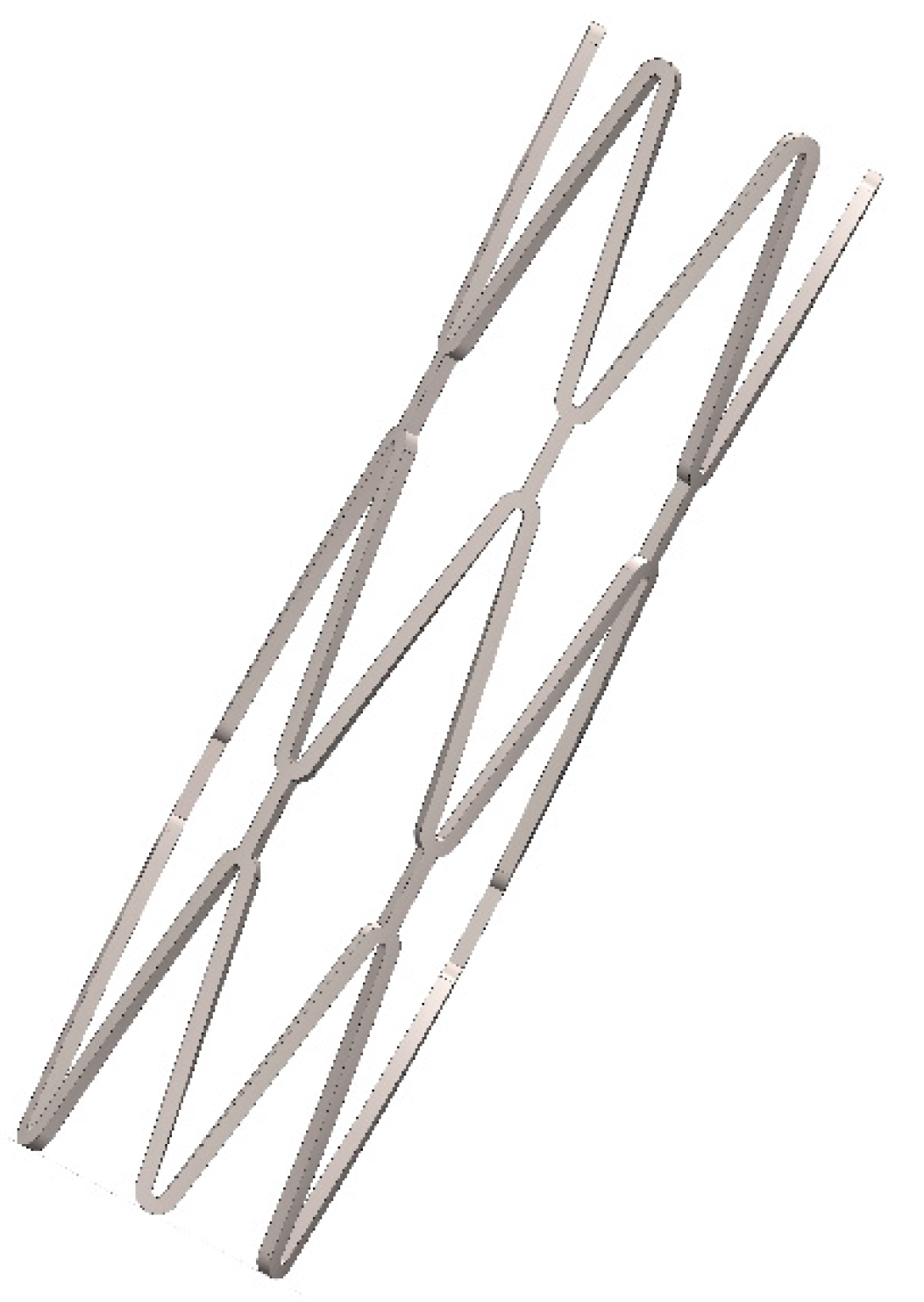
In this paper, a parametric design scheme, integrated with the developed FEA and CFD models, was implemented in our design process to reduce the design iteration time [16,17]. It is a method of linking device dimensions to geometry in such a way that when the defined design parameters change, the design drawing changes as well. Important device geometries such as tubing diameter, strut geometry, and crown radius and number are parameterized by mathematical equations. Once the drawings are generated, computational analysis is used to screen out inadequate designs before lengthy prototyping and bench testing procedures begin. This integrated CAD (Computer Aided Design)/FEA/CFD scheme is able to cut the design iteration time significantly; used in the medical device industry, it can save precious time and reduce a single-product development cycle from months to weeks. Figure 1 shows the initial cylindrical configuration of the spherical occlusion device at 2.0 mm. Here, a 2-D drawing of the spherical occlusion device was first sketched and then wrapped onto a 3-D cylinder to create the 3-D cylindrical design pattern in SolidWorks (Dassault Systemes SolidWorks Corp., Waltham, MA, USA). This device has to withstand large deformation without fracture during the dramatic shape and size transformations from crimping to expansion and from cylinder to sphere. Computer simulations including FEA and CFD were implemented next to predict the device integrity and find the optimized design.
2.2. Finite Element Models
Computational modeling provides extensive information under a highly-controlled environment, making it possible to screen numerous device design iterations prior to costly prototyping. The ABAQUS/Standard finite element solver (Dassault Systemes Simulia Corp., Providence, RI, USA) was used with its super-elastic user-defined material subroutine UMAT. This subroutine is able to capture the unique stress-strain behavior with the pronounced hysteresis loop of the nitinol material during simulations [18,19]. Finite element models were developed to evaluate the device’s integrity when subjected to various loading conditions, including multiple device expansions and their subsequent heat treatments during manufacturing, crimping of the device inside a catheter, and releasing it into a blood vessel. These numerical procedures were simulated with the following steps:
- Expand the device’s diameter to 2.0 mm, 3.0 mm, 4.0 mm, and 5.2 mm. Anneal the device after each expansion to remove residual stresses.
- Crimp the device inside a 1.6 mm cylindrical catheter for delivery.
- Release the device into a 5.2 mm artery model.
A 1.5 mm inner sphere, a 6.0 mm outer sphere, and a 10.0 mm outer cylinder were created in the FEA models to simulate the expansion and crimping procedures. In each expansion and its subsequent heat treatment, the 1.5 mm sphere, placed inside the device, was expanded sequentially and continuously to open the device to the next target size. The stress and strain in each element were reset to zero to simulate the removal of residual stresses. The device deformed geometry was extracted for the next expansion until the final device diameter of 5.2 mm was reached. The 6.0 mm outer sphere was then placed outside the device to help shape the device into a perfect sphere from the outside. After the shaping step, the 10.0 mm outer cylinder was used to crimp the device to the catheter size of 1.6 mm. Finally, the deployment of the device was simulated by releasing the outer cylinder to 5.2 mm, allowing the device to self-expand to its final dimension. The element type C3D8I (incompatible mode eight-node brick element) was used to simulate the spherical occlusion device, while the element type SFM3D4R (reduced integration four-node quadrilateral surface element) was used for both spheres and the cylinder.
2.3. Computational Fluid Dynamics Model
The blood flow was governed by the continuity equation and the Navier-Stokes equation:
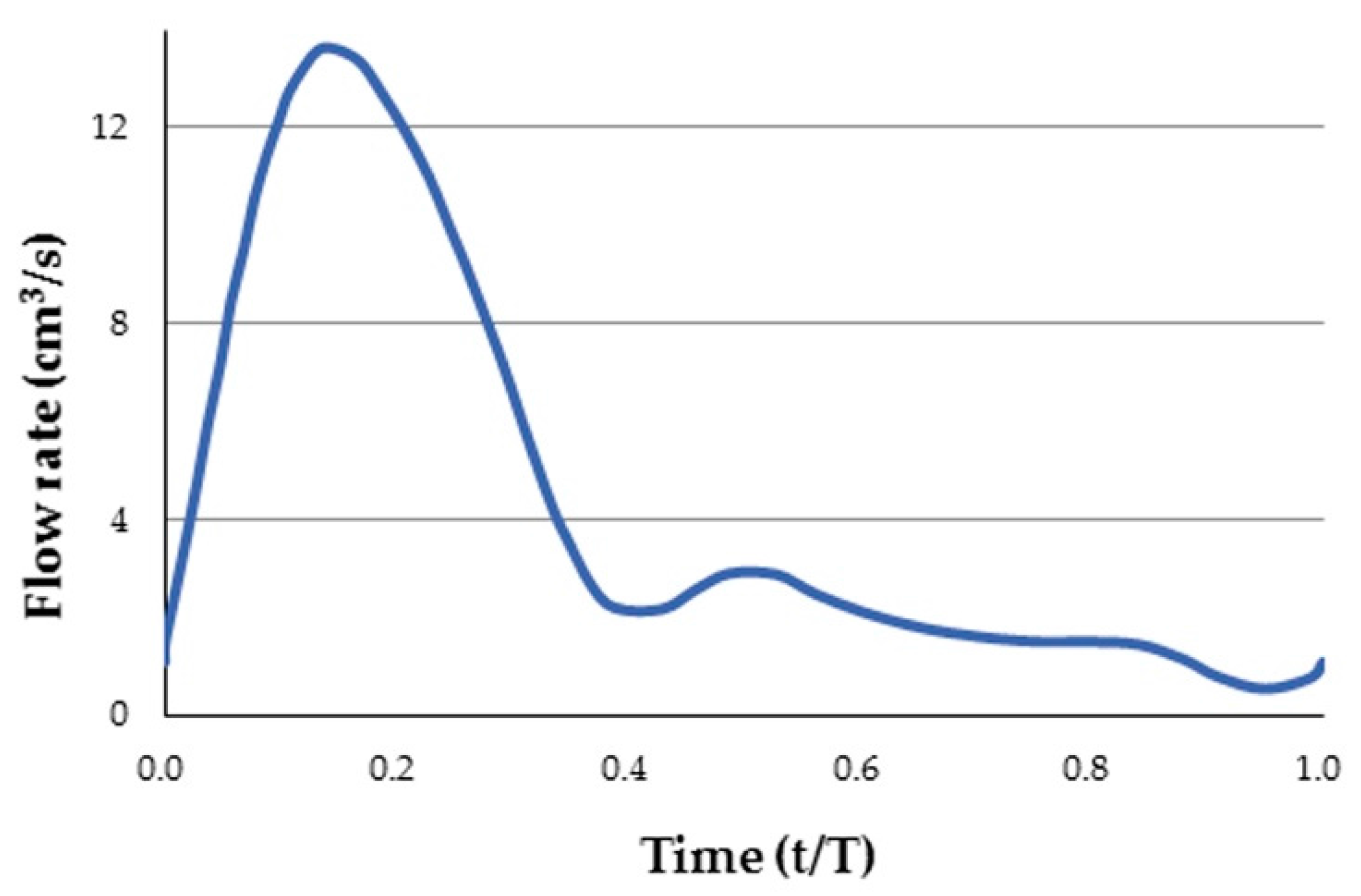
Several assumptions were made in the CFD model. The blood flow was assumed to be incompressible and laminar, with a blood density of 1060 kg/m3. The FLUENT software (ANSYS, Inc., Canonsburg, PA, USA) was used to solve these governing equations. The boundary condition of the artery wall was assumed to be no-slip. A fully-developed pulsatile flow was prescribed at the inlet (Figure 2), while a uniform pressure was prescribed at the outlet. The Carreau model was used to describe the non-Newtonian behavior of the blood flow as follows:
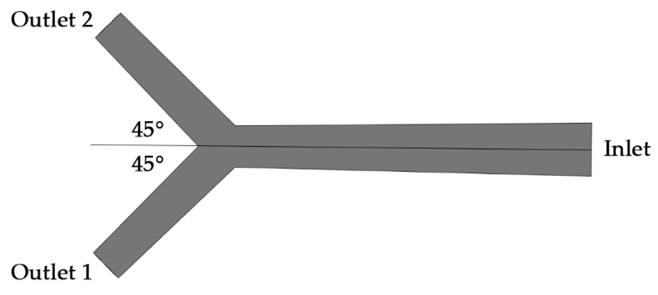
where is the viscosity at infinite shear rate, is the viscosity at zero shear rate, is the relaxation time, and n is the power index related to the material. These parameters were obtained by fitting the Carreau model to the experimental data: = 0.0035 kg/ms, = 0.25 kg/ms, = 25.0 s, and n = 0.25 [20,21,22,23]. A simple hepatic artery bifurcation model was built, with an inlet of 6 mm in diameter and two outlets of 4 mm in diameter (Figure 3). The angle between outlet 1 and outlet 2 was designed to be 90°. The spherical occlusion device was placed at the upstream of outlet 2, with two different metal densities of 14% and 27% evaluated.
The stent CFD model was meshed with the 4-node linear tetrahedron element in the lumen area, but with the 6-node linear wedge (prism) element near the artery wall where the inflation layers were used to capture the high-gradient variations near the boundary. A mesh sensitivity study was conducted to evaluate the flow rates at the inlet and outlets (without the spherical occlusion device) when t = 0.14 s for various element numbers starting from approximately 500,000 to 3,000,000 with increments of 500,000 (Table 1). Simulated results converged relatively quickly and their values became stabilized when the element number was greater than 1,500,000. Therefore, we selected a conservative value of 2,500,000 as the final element number for all cases investigated to ensure that variations in the flow behavior were adequately captured.
2.4. Prototyping
Producing the spherical occlusion device requires laser-cutting of the designed pattern onto a nitinol hypotube, followed by an alternating series of expansions and heat treatments as it is gradually shaped into a sphere using customized tooling. The repeated heat treatment in each expansion stage relieves all residual stresses within the device, thus allowing subsequent expansion to the next size without fractures. Through these procedures, a nitinol spherical occlusion device designed for the purposes of flow occlusion can be produced.
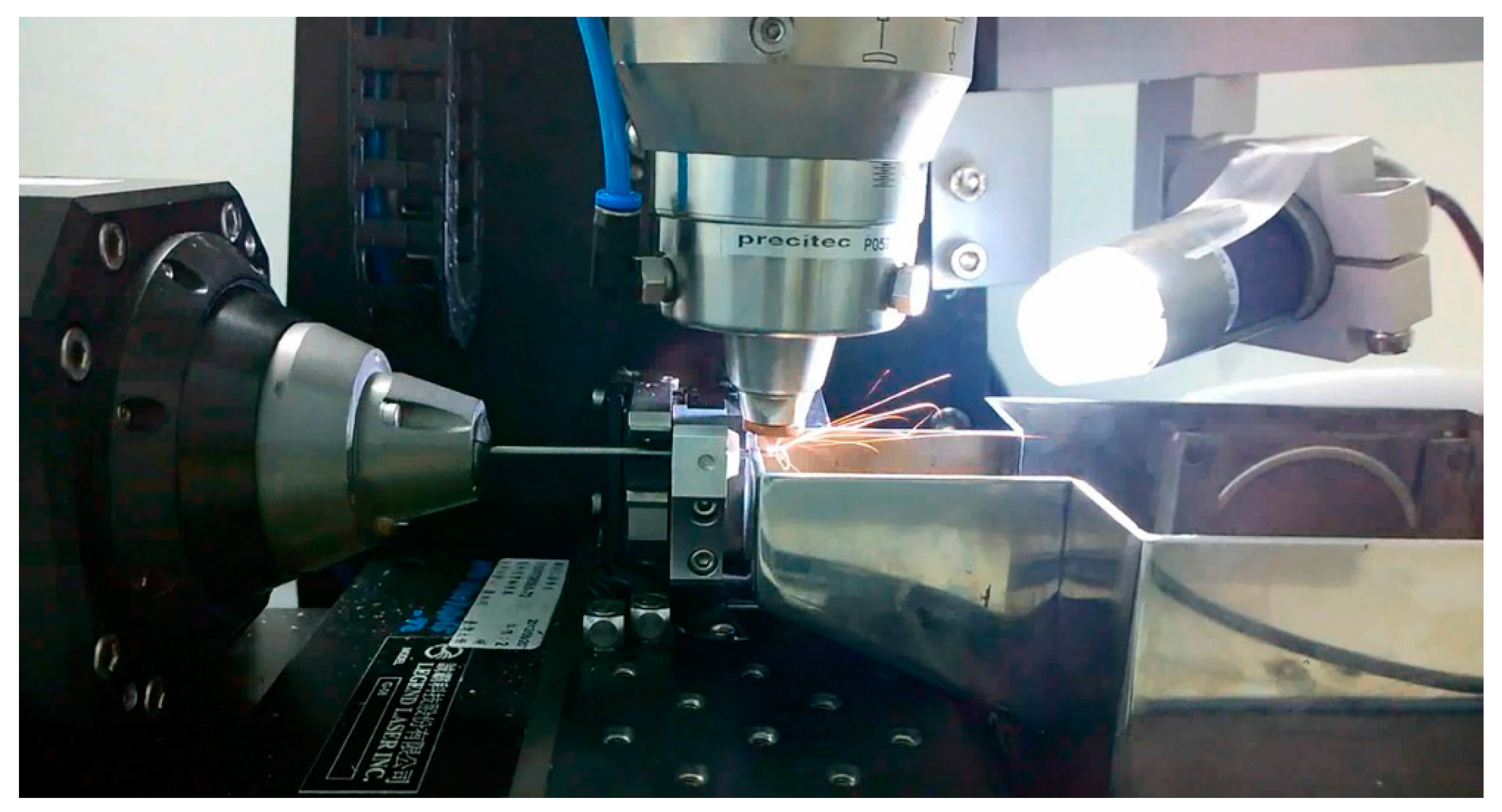
A laser module consisting of a Rofin 100 W pulsed fiber laser, an Aerotech linear X–Y motor stage, and a Z-direction server motor were integrated, with Argon as the assisted gas. The linear motion and rotation of the hypotube were provided by the linear X–Y motor stage, while the distance between the laser source and hypotube surface was controlled by the Z-direction server motor to achieve the optimal focal depth. A 2-D drawing was first sketched on the X–Y plane and then coded into the 3-D cylindrical coordinate system. The design pattern was cut onto a seamless hypotube based on the coded geometry (Figure 4). The control algorithm used to coordinate the linear X–Y motor stage with the timing of laser firing was the Position Synchronized Output.
Nitinol possesses the properties of super elasticity and shape memory, allowing the device to memorize and return to its designed shape upon release. In order to create such behavior, special heat treatment was implemented after laser cutting to shape the device to the desired levels. Steel balls with diameters of 2.0 mm, 3.0 mm, 4.0 mm, and 5.2 mm were used sequentially to expand the device to its target size (Figure 5a). After the final diameter was reached, a special fixture was used to help shape the device into a perfect sphere from the outside (Figure 5b). Heat treatment was applied after each expansion stage to shape the device and relieve its residual stresses. The two most important parameters for heat treatment are time and temperature. The high temperatures associated with laser cutting and heat treatment may create spatter, oxide layers, and other debris that must be removed with further surface finishing. Surface finishing was accomplished in two major steps: sand-blasting and electro-polishing. Experiments were conducted to optimize the combination of processing parameters for heat treatment and surface finishing.
2.5. Flow Experiments
To evaluate the device occlusion performance, two types of flow experiments were conducted: an occlusion experiment and a digital particle image velocimetry (DPIV) experiment. A plastic bifurcate hepatic artery model, similar to the one mentioned in Section 2.3, was manufactured and connected to a tubing system. The spherical occlusion device was deployed at the upstream of outlet 2 to evaluate its occlusion performance, as shown in Figure 6. A blood simulating fluid, phosphate buffered saline (PBS) buffer solution (Biokit Biotechnology Inc., Miaoli County, Taiwan), was used as the operating fluid.
In the occlusion experiment, 500 mL PBS buffer solution from a beaker was supplied to the inlet of the hepatic artery model through a communicating pipe and a vertical burette (Figure 6). Two more beakers were placed at the downstream of this open-loop tubing system to collect and measure the fluid volumes from outlet 1 and outlet 2, respectively. The spherical occlusion device with the metal density of 27% was tested and the occlusion rate was calculated as:
where is the fluid volume collected from outlet 2 without occlusion and is the fluid volume collected from outlet 2 with occlusion.
Digital particle image velocimetry (DPIV) experiments were also conducted to evaluate the occlusion performance with the same hepatic artery model connected to a closed-loop tubing system. A peristaltic pump (Gamma X, ProMinent Corp., Heidelberg, Germany) was used to generate a pulsatile flow of 72 beats per minute to simulate the blood flow driven by the cardiac impulse. Flow-field visualizing particles (Long Win Science and Technology Corp, Miaoli County, Taiwan) of 30 μm in diameter were added into the solution. In order to illuminate the particles and visualize the flow, a 300 W green laser was refracted to create a sheet of light. A 25-frame per second digital camera was placed perpendicular to the light sheet to capture images of illuminated particles. MATLAB PIVlab (developed by Dr. William Thielicke and Prof. Dr. Eize J. Stamhuis) was used to analyze the visualized flow field [24,25,26,27]. Contrast limited adaptive histogram equalization (CLAHE) was applied to increase the contrast of the images. Direct Fourier Transform Correlation with Multiple Passes and Deforming Windows (FFT window deformation) was chosen as the DPIV algorithm. Two passes with interrogation areas of 64 pixels and 32 pixels were used.
3. Results
In this paper, we propose a novel nitinol “spherical occlusion device” for future cancer treatment. This is the first of its kind in the world and also represents the first “spherical” variation from traditional cylindrical stents. Such a shape transformation was achieved through a series of expansions and heat treatments. Figure 7 shows the FEA contour plots of strain distribution during a series of expansions. It was found that the maximum strain of the device usually occurred at the inner surface of the most-curved region. At the end of each expansion, the subsequent heat treatment relieved all stresses within the device, which became stress-free. The deformed geometry of the device was then extracted for the next expansion until the final diameter of 5.2 mm was reached.
The spherical occlusion device has to withstand large deformation without fracturing during the dramatic shape transformations from crimping to expansion and from cylinder to sphere. FEA simulation results showed that the maximum strain encountered during the entire process was 10.0% when the device was crimped inside a catheter of 1.6 mm diameter for delivery. Since the nitinol failure strain is approximately 12%, this shows that our device is able to withstand large deformation safely. Table 2 lists the maximum strains encountered during the manufacturing and deployment procedures.
A hepatic artery bifurcation model was used to evaluate the device’s occlusion performance. The device was placed at the upstream of outlet 2, as shown in Figure 3 and Figure 6. CFD simulation results showed that devices with metal densities of 27% and 14% were able to reduce the blood flow by 50% and 30%, respectively (Figure 8). The reduction of the blood flow in the target branch implied that a portion of the blood flow was redirected towards the other branch, according to the conservation of mass. The spherical occlusion device can be custom-made by tailoring its metal density to reduce blood flow by specific amounts.
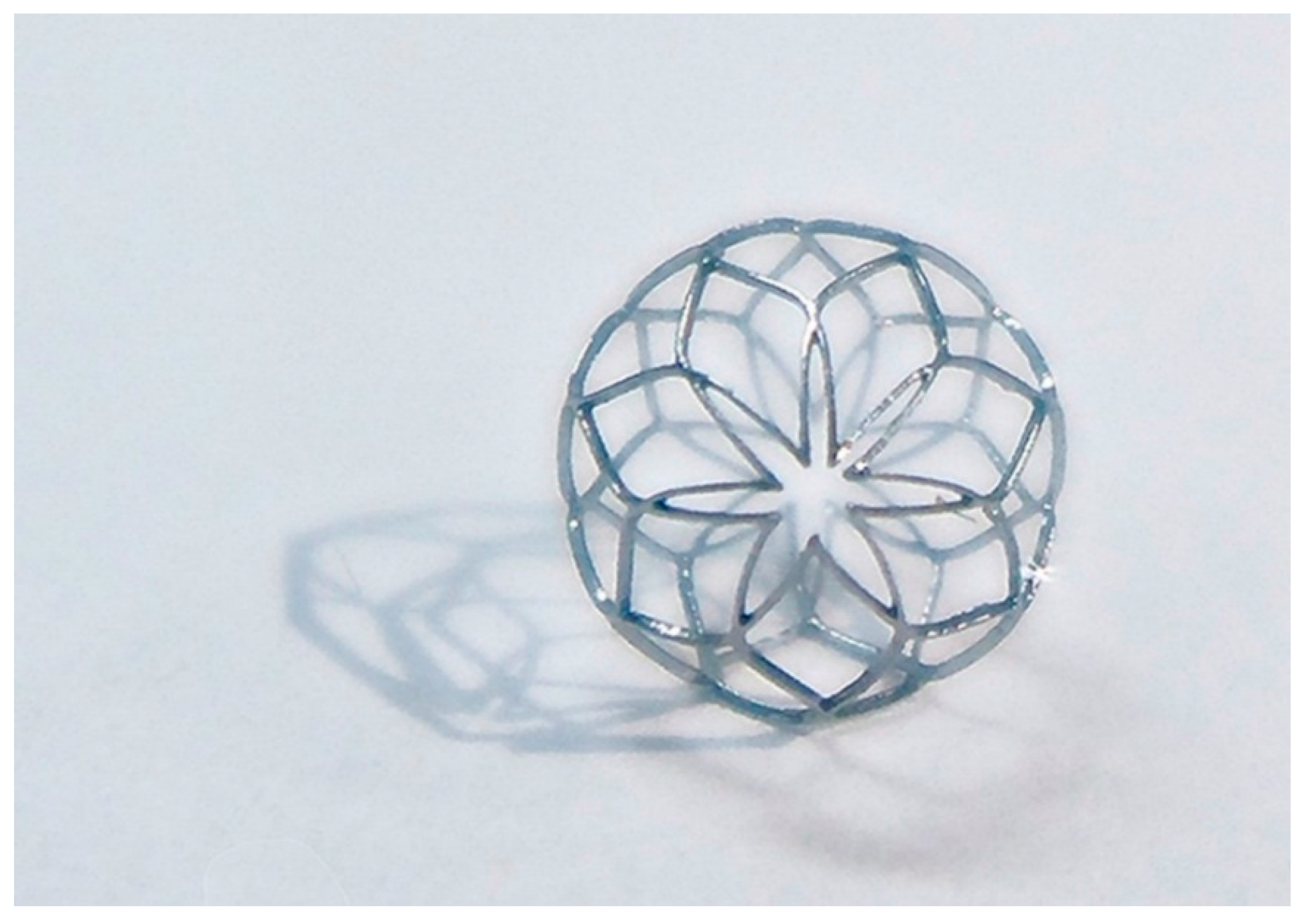
During heat treatment, the two most important parameters are temperature and time. Higher temperature and longer operating time negatively impact the device’s mechanical properties. After laser cutting, the spherical occlusion device was expanded gradually to the desired shape and diameter and heat-treated multiple times in a salt bath at 500 °C for 200 s. The device surface was then sand-blasted and electro-polished to achieve a mirror-like surface finish. Sand-blasting was first applied with aluminum oxide particles (37–44 μm) sprayed at a pressure of 2 kg/cm2 for one minute to remove large debris, followed by electro-polishing to further improve the surface conditions. The electro-polishing solution was a mixture of 79% (volume) of acetic acid and 21% (volume) of perchloric acid. The anode and cathode were made of a stainless steel flake and a titanium wire, respectively. The electro-polishing process was conducted at room temperature in two stages, with the first stage at 7.7 volts for 60 s and the second stage at 11.3 volts for another 60 s. Figure 9 presents the world’s first prototype of the spherical occlusion device for demonstration of our novel design concept.
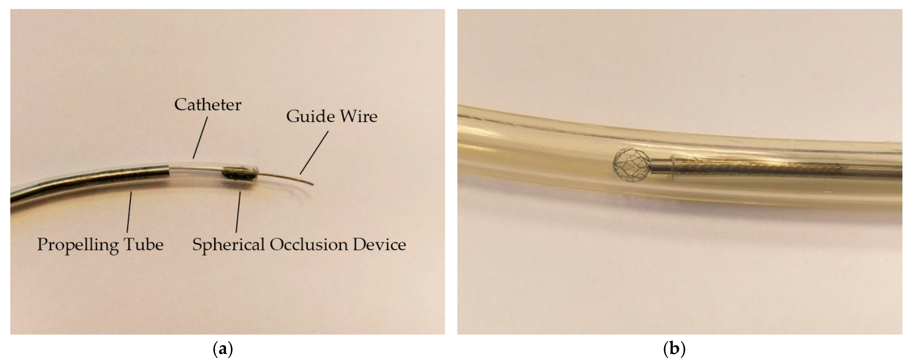
Prior to the occlusion experiments, the spherical occlusion device was deployed at the upstream of outlet 2 using a home-made assembly of the delivery system including a guide wire, a catheter, and a propelling tube. The spherical occlusion device was crimped inside the catheter cylindrically, while the guide wire ran through its center as shown in Figure 10a. The guide wire was delivered to the far distal end of outlet 2 in the artery model to provide support, while the rest of the components followed the guide wire to the target site. The propelling tube, sitting between the catheter and the guide wire, moved forward to push the occlusion device out of the catheter for deployment. The spherical occlusion device expanded to its full spherical shape in the artery model, as shown in Figure 10b. Comparing Figure 10a,b, the spherical occlusion device proved to withstand large deformation without fractures during the dramatic shape transformation from crimping to expansion and from cylinder to sphere.
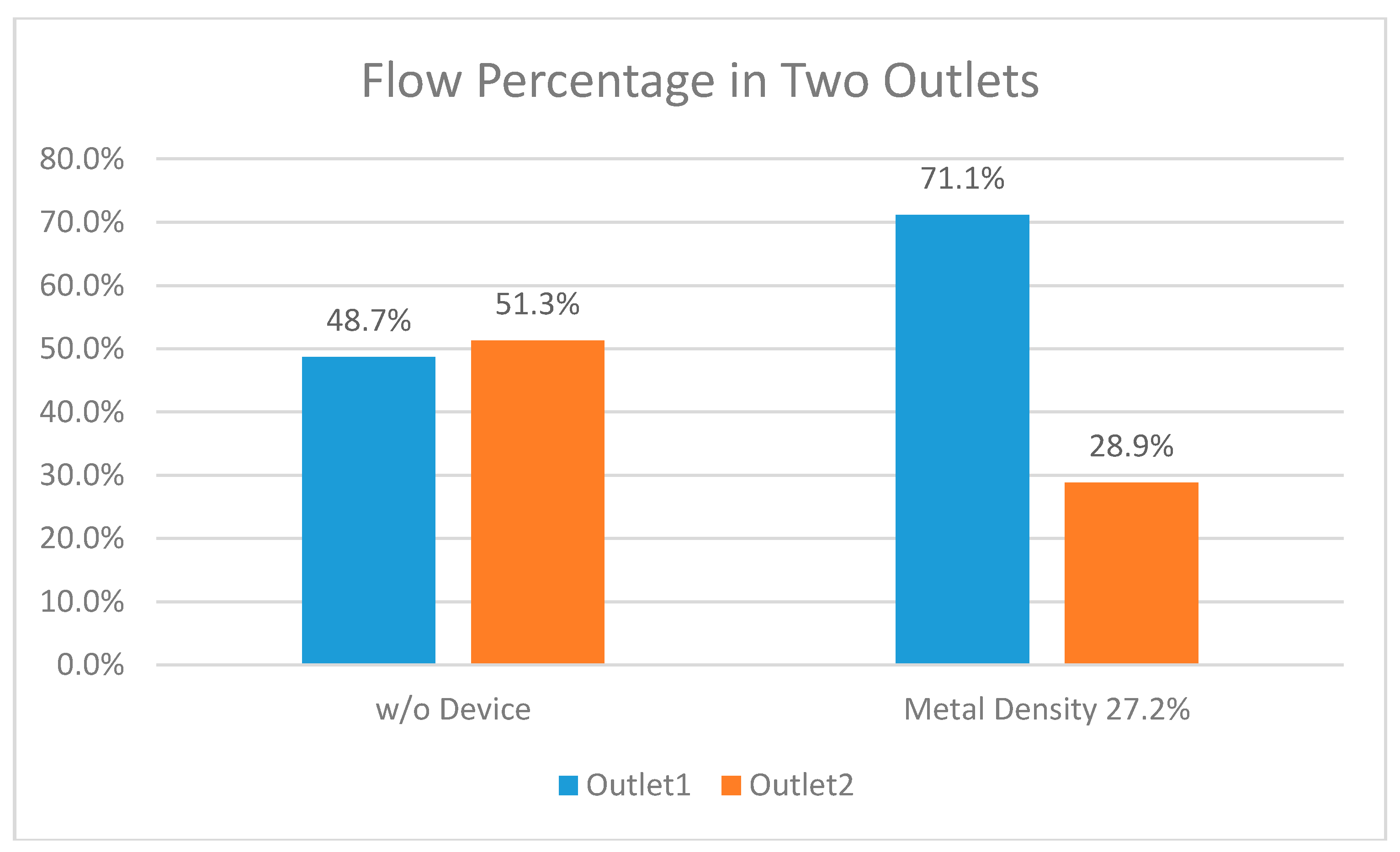
In the occlusion experiment, 500 mL PBS buffer solution from a beaker was supplied to the inlet of the hepatic artery model. Fluids flowing out from both outlets were collected and measured to evaluate the performance of the spherical occlusion device (metal density of 27%). As shown in Figure 11, the fluid volumes collected from both outlets were nearly identical before the occlusion device was placed (48.7% for outlet 1 vs. 51.3% for outlet 2). However, when the occlusion device was placed at outlet 2, the fluid volumes collected from both outlets changed drastically to 71.1% and 28.9% for outlets 1 and 2, respectively. This showed that 44% of the flow at outlet 2 was successfully reduced by the presence of the occlusion device and redirected to outlet 1 instead. With the metal density of 27%, the flow was reduced by 44% which agreed well with the CFD simulations. This occlusion experiment proves that the spherical occlusion device is able to reduce the blood flow as designed by tailoring the device’s metal density.
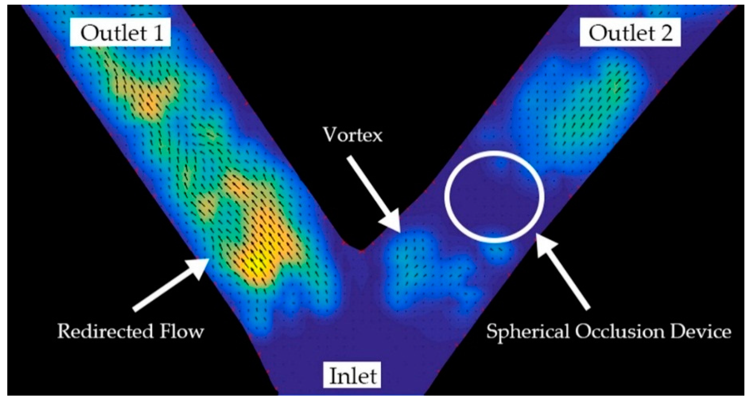
Figure 12 shows a DPIV image taken at the peak point of the pulsatile flow in Figure 8. It clearly shows the formation of a vortex located at the upstream or proximal side of the spherical occlusion device. The particle velocity at outlet 1 increased significantly, while the particle velocity at outlet 2 decreased. Since the diameters of the two branches were identical, the flow rate was proportional to the particle velocity. This suggested that the flow rate was far greater at outlet 1 than at outlet 2. According to the conservation of mass, it implied that the flow at outlet 2 was redirected to outlet 1 after the device was deployed. DPIV results showed that the spherical occlusion device successfully reduced the flow to levels that agreed well with the CFD numerical simulations.
4. Discussion
The spherical occlusion device is a new treatment option for liver cancers. We believe that such occlusion devices could also be extended to other types of cancers elsewhere in the body. The spherical shape was chosen over other geometries for better fit inside an artery. The typical shape of the commercial plug devices is usually double-cone (dog-bone), cylindrical, or umbrella which has a longer contacting zone with the artery. Since most of the arteries are tapered from the proximal to the distal end, this may create some size mismatch issue where the distal section of the artery is over-expanded by the plug yet the proximal section is mal-apposed (not fully contacted). Our proposed spherical occlusion device’s contact zone with the artery is merely a circumferential ring, potentially minimizing the size mismatch issue.
Nitinol alloy was chosen as our device’s material due to its excellent super-elasticity and biocompability. Biocompatibility of an alloy is directly related to the corrosion behavior of the material in a specified solution and the tendency for the alloy to release its potential toxic ions. To quantify toxicity, inhibition of mitosis in human fibroblasts in tissue cultures exposed to test materials is an accepted screening method. Results showed that no significant toxicity effects were found in nitinol [28]. Literature reviews generally indicate that nitinol has extremely good biocompatibility due to the formation of a passive titanium-oxide layer (TiO2). This oxide layer not only increases the stability of the surface layers by protecting the bulk material from corrosion, but also creates a physical and chemical barrier against Ni oxidation and modifies the oxidation pathways of Ni [13]. However, nitinol has its limitations when applied as an implant in some cases. Peripheral stents made of nitinol suffer stent fracture issues which may in turn cause restenosis. Schlager et al. compared the rates of restenosis, and their results showed that restenosis remains a major problem even with current nitinol stent technology [29].
Another potential indication for the spherical occlusion device is the intracranial aneurysm. An intracranial aneurysm is a cerebrovascular disorder in which weakness in the cerebral arterial wall causes localized ballooning of the blood vessel. As the aneurysm grows, it puts pressure on surrounding brain tissues and may eventually rupture, leading to life-threatening hemorrhagic stroke. Our spherical occlusion device is able to fit the aneurysm geometry nicely and provide more gentle and uniform radial support to an intracranial aneurysm, thereby reducing the risk of rupture. In addition, it can be directly deployed inside the aneurysm and block the blood flow in a single step, which significantly shortens the surgery time.
When the spherical occlusion device is used to treat intracranial aneurysm, the occlusion rate has to be as high as possible. As mentioned in this paper, the occlusion rate is mainly controlled by the device’s metal density. However, since the device has to be crimped inside a catheter for delivery, the device’s metal density has an upper limit, beyond which the device becomes too dense to pack. To overcome this issue, we are currently pursuing several alternative ideas. For example, a covered stent made of a metallic frame covered by an extremely durable fabric, such as polyester, is likely to provide almost total occlusion. Similar effects could also be achieved via electro-spinning to coat a thin layer of film on our spherical occlusion device. Another novel concept is to place a smaller sphere inside a larger sphere to effectively increase the overall metal density without having to change the metal density of an individual sphere. These two spheres could be crimped inside a catheter end-to-end and delivered sequentially in a single deployment. In summary, we are currently pursuing several options to achieve our goal without physically increasing the device’s metal density.
Fortunately, when the spherical occlusion device is used to treat cancers, the occlusion rate will not have to be too high. It is our intention to leave sufficient blood flow to carry chemotherapy and radioactive drugs downstream to the lesion site and treat cancers more effectively. The drugs could be administered by controlling the metal density of the occlusion device and drug release rate to maximize the therapeutic outcome.
The spherical occlusion device is crimped inside a catheter for delivery to the lesion site and deployed at the upstream location of the cancer cells to reduce their blood supply. It can stay inside the body for months as needed and be retrieved by catheter when the task is completed. A “hook-and-loop” mechanism can be designed, with the hook on the catheter side and the loop on the device side. During retrieval, the hook on the catheter can engage and catch the loop to bind the device to the catheter.
5. Conclusions
In this paper, an alternative treatment option for cancers in the future—the spherical occlusion device—is proposed. This spherical occlusion device can reduce the blood supply to cancer cells to certain degrees when deployed at the upstream of the hepatic artery. A parametric design scheme was implemented in this study and successfully reduced the design iteration time for this device. Computational FEA and CFD models were developed to simulate the mechanical integrity and occlusion performance of the spherical occlusion device. CFD simulation results showed that significant reduction of the blood flow rate by 30–50% was feasible when the metal density of the device was 14–27%. A conceptual prototype, the first of its kind in the world, was cut by pulsed-fiber optic laser before undergoing a series of expansions and heat treatments to shape the device to its final geometry. Flow experiments were conducted for proof of concept, and results showed that the spherical occlusion device successfully reduced the flow as designed. The occlusion device with the metal density of 27% was able to reduce 44% of flow, which agreed well with the CFD simulations. We believe that the novel spherical occlusion device proposed in this paper will add a new dimension to future cancer treatments.
Acknowledgments
This research was supported by the Ministry of Science and Technology in Taiwan through Grant MOST-105-2221-E-002-092-MY3. The authors are grateful for the support and help.
Author Contributions
The novel concept of this spherical occlusion device for cancers was developed by Hao-Ming Hsiao. Computational simulations were performed by Chien-Erh Lin and Yi-Ping Wang. Prototyping of this device, including laser cutting, heat treatment, and electro-polishing, were made possible by Tzu-Yuan Lin, Chien-Erh Lin, and Han-Yu Lee. The fluid dynamics experiments were conducted by Tzu-Yuan Lin and Chien-Erh Lin.
Conflicts of Interest
The authors declare no conflict of interest.
References
- Stewart, B.W.; Wild, C.P. Liver Cancer. In World Cancer Report 2014; International Agency for Research on Cancer: Lyon, France, 2014; pp. 403–412. [Google Scholar]
- Boscha, F.X.; Ribesa, J.; Díaza, M.; Cléries, R. Primary Liver Cancer: Worldwide Incidence and Trends. Gastroenterology 2004, 127, 5–16. [Google Scholar] [CrossRef]
- Beasley, R.P.; Lin, C.C.; Hwang, L.Y.; Chien, C.S. Hepatocellular Carcinoma and Hepatitis B virus: A Prospective Study of 22,707 Men in Taiwan. Lancet 1981, 318, 1129–1133. [Google Scholar] [CrossRef]
- Perz, J.F.; Armstrong, G.L.; Farrington, L.A.; Hutin, Y.J.F.; Bell, B.P. The contributions of hepatitis B virus and hepatitis C virus infections to cirrhosis and primary liver cancer worldwide. J. Hepatol. 2006, 45, 529–538. [Google Scholar] [CrossRef] [PubMed]
- Arbuthnot, P.; Kew, M. Hepatitis B virus and hepatocellular carcinoma. Int. J. Exp. Pathol. 2001, 82, 77–100. [Google Scholar] [CrossRef] [PubMed]
- Fattovich, G.; Stroffolini, T.; Zagni, I.; Donato, F. Hepatocellular carcinoma in cirrhosis: Incidence and risk factors. Gastroenterology 2004, 127, 35–50. [Google Scholar] [CrossRef]
- Donato, F.; Tagger, A.; Gelatti, U.; Parrinello, G.; Boffetta, P.; Albertini, A.; Decarli, A.; Trevisi, P.; Ribero, M.L.; Martelli, C.; et al. Alcohol and hepatocellular carcinoma: The effect of lifetime intake and hepatitis virus infections in men and women. Am. J. Epidemiol. 2002, 155, 323–331. [Google Scholar] [CrossRef] [PubMed]
- Hassan, M.M.; Hwang, L.Y.; Hatten, C.J.; Swaim, M.; Li, D.; Abbruzzese, J.L.; Beasley, P.; Patt, Y.Z. Risk factors for hepatocellular carcinoma: Synergism of alcohol with viral hepatitis and diabetes mellitus. Hepatology 2002, 36, 1206–1213. [Google Scholar] [CrossRef] [PubMed]
- Denekamp, J.; Hill, S.A.; Hobson, B. Vascular occlusion and tumour cell death. Eur. J. Cancer Clin. Oncol. 1983, 19, 271–275. [Google Scholar] [CrossRef]
- Yamada, R.; Sato, M.; Kawabata, M.; Nakatsuka, H.; Nakamura, K.; Takashima, S. Hepatic artery embolization in 120 patients with unresectable hepatoma. Radiology 1983, 148, 397–401. [Google Scholar] [CrossRef] [PubMed]
- Karnofsky, D.A. Meaningful clinical classification of therapeutic responses to anti-cancer drugs. Clin. Pharmacol. Ther. 1961, 2, 709–712. [Google Scholar] [CrossRef] [PubMed]
- Hill, S.L.; Hijazi, Z.M.; Hellenbrand, W.E.; Cheatham, J.P. Evaluation of the Amplatzer vascular plug for embolization of peripheral vascular malformations associated with congenital heart disease. Catheter. Cardiovasc. Interv. 2006, 67, 112–118. [Google Scholar] [CrossRef] [PubMed]
- Duerig, T.W.; Pelton, A.; Stöckel, D. An Overview of Nitinol Medical Applications. Mater. Sci. Eng. A Struct. 1999, 273, 149–160. [Google Scholar] [CrossRef]
- Machado, L.G.; Savi, M.A. Medical applications of shape memory alloys. Braz. J. Med. Biol. Res. 2003, 36, 683–691. [Google Scholar] [CrossRef] [PubMed]
- Hsiao, H.M.; Yeh, C.T.; Wang, C.; Chao, L.H.; Li, D.R. Effects of stent design on new clinical issue of longitudinal stent compression in interventional cardiology. Biomed. Microdevices 2014, 16, 599–607. [Google Scholar] [CrossRef] [PubMed]
- Hsiao, H.M.; Chiu, Y.H.; Lee, K.H.; Lin, C.H. Computational modeling of effects of intravascular stent design on key mechanical and hemodynamic behavior. Comput. Aided Des. 2012, 44, 757–765. [Google Scholar] [CrossRef]
- Hsiao, H.M.; Wang, Y.P.; Ko, C.Y.; Cheng, Y.H.; Lee, H.Y. A novel nitinol spherical occlusion device for liver cancer. Materials 2016, 9, 19. [Google Scholar] [CrossRef]
- Pham, T.M.; DeHerrera, M.; Sun, W. Analysis and simulation of PTMA device deployment into the coronary sinus: Impact of stent strut thickness. Mech. Biol. Syst. Mater. 2011, 2, 1–10. [Google Scholar]
- Hsiao, H.M.; Yin, M.T. An intriguing design concept to enhance the pulsatile fatigue life of self-expanding stents. Biomed. Microdevices 2014, 16, 133–141. [Google Scholar] [CrossRef] [PubMed]
- Chien, S.; Usami, S.; Taylor, H.M.; Lundberg, J.L.; Gregersen, M.I. Effects of hematocrit and plasma proteins on human blood rheology at low shear rates. J. Appl. Physiol. 1966, 21, 81–87. [Google Scholar] [PubMed]
- Seo, T.; Schachter, L.G.; Barakat, A.I. Computational study of fluid mechanical disturbance induced by endovascular stents. Ann. Biomed. Eng. 2005, 33, 444–456. [Google Scholar] [CrossRef] [PubMed]
- Hsiao, H.M.; Lin, C.H.; Liao, Y.C.; Chen, H.Y.; Wang, T.W. Hemodynamic behavior of coronary stents in straight and curved arteries. Curr. Nanosci. 2014, 10, 205–211. [Google Scholar] [CrossRef]
- Hsiao, H.M.; Lee, K.H.; Liao, Y.C.; Cheng, Y.C. Cardiovascular stent design and wall shear stress distribution in coronary stented arteries. Micro Nano Lett. 2012, 7, 430–433. [Google Scholar] [CrossRef]
- Thielicke, W.; Stamhuis, E.J. PIVlab—Towards User-friendly, Affordable and Accurate Digital Particle Image Velocimetry in MATLAB. J. Open Res. Softw. 2014, 2, e30. [Google Scholar] [CrossRef]
- PIVlab—Time-Resolved Digital Particle Image Velocimetry Tool for MATLAB (Version: 1.41). Available online: http://0-dx-doi-org.brum.beds.ac.uk/10.6084/m9.figshare.1092508 (accessed on 9 March 2017).
- Thielicke, W. The Flapping Flight of Birds—Analysis and Application. Ph.D. Thesis, University of Groningen, Groningen, The Netherlands, 31 October 2014. [Google Scholar]
- Garcia, D. A fast all-in-one method for automated post-processing of PIV data. Exp. Fluids 2011, 50, 1247–1259. [Google Scholar] [CrossRef] [PubMed]
- Putters, J.L.M.; Sukul, K.; de Zeeuw, G.R.; Bijma, A.; Besselink, P.A. Comparative Cell Culture Effects of Shape Memory Metal (Nitinol), Nickel and Titanium: A Biocompatibility Estimation. Eur. Surg. Res. 1992, 24, 378–382. [Google Scholar] [CrossRef] [PubMed]
- Schlager, O.; Dick, P.; Sabeti, S.; Amighi, J.; Mlekusch, W.; Minar, E.; Schillinger, M. Long-Segment SFA Stenting—The Dark Sides: In-Stent Restenosis, Clinical Deterioration, and Stent Fractures. J. Endovasc. Ther. 2005, 12, 676–684. [Google Scholar] [CrossRef] [PubMed]
Figure 1.
Initial cylindrical configuration of spherical occlusion device.

Figure 2.
Fully-developed pulsatile flow prescribed at the inlet.

Figure 3.
Hepatic artery bifurcation model for numerical simulations.

Figure 4.
Cutting the design pattern of the spherical occlusion device onto a hypotube by laser.

Figure 5.
(a) Steel ball expanding the spherical occlusion device; (b) Special fixture for shaping the device into a perfect sphere from the outside.
Figure 5.
(a) Steel ball expanding the spherical occlusion device; (b) Special fixture for shaping the device into a perfect sphere from the outside.

Figure 6.
Hepatic artery model (left) and occlusion experiment setup (right).

Figure 7.
Contour plots of strain distribution during a series of expansions.

Figure 8.
Reduction of blood flow by occlusion device in single pulse at outlet 2.

Figure 9.
World’s first spherical occlusion device.

Figure 10.
Deployment of spherical occlusion device. (a) Spherical occlusion device crimped inside catheter; (b) Spherical occlusion device expanded to its full sphere after deployment.
Figure 10.
Deployment of spherical occlusion device. (a) Spherical occlusion device crimped inside catheter; (b) Spherical occlusion device expanded to its full sphere after deployment.

Figure 11.
Fluid volume measurements at both outlets before vs. after occlusion.

Figure 12.
Digital particle image velocimetry (DPIV) image showing successful occlusion performance.
Figure 12.
Digital particle image velocimetry (DPIV) image showing successful occlusion performance.


Table 1.
Mesh sensitivity study for stent computational fluid dynamics (CFD) model.
| Total Element Number | Flow Rate at Inlet, cm3/s | Flow Rate at Outlet 1, cm3/s | Flow Rate at Outlet 2, cm3/s |
|---|---|---|---|
| 597,575 | 13.668 | 6.837 | 6.831 |
| 1,042,898 | 13.658 | 6.834 | 6.823 |
| 1,410,707 | 13.654 | 6.831 | 6.822 |
| 1,936,959 | 13.651 | 6.830 | 6.821 |
| 2,548,140 | 13.647 | 6.827 | 6.820 |
| 3,155,138 | 13.647 | 6.826 | 6.820 |
Table 2.
Maximum strains encountered during manufacturing and deployment procedures.
| Manufacturing/Deployment | Maximum Strain |
|---|---|
| Expansion to 2.0 mm | 0.1% |
| Expansion to 3.0 mm | 4.6% |
| Expansion to 4.0 mm | 6.5% |
| Expansion to 5.2 mm | 9.1% |
| Crimping to 1.6 mm | 10.0% |
© 2017 by the authors. Licensee MDPI, Basel, Switzerland. This article is an open access article distributed under the terms and conditions of the Creative Commons Attribution (CC BY) license (http://creativecommons.org/licenses/by/4.0/).
Share and Cite
MDPI and ACS Style
Hsiao, H.-M.; Lin, T.-Y.; Lin, C.-E.; Lee, H.-Y.; Wang, Y.-P. Innovation of New Occlusion Devices for Cancers. Appl. Sci. 2017, 7, 530. https://0-doi-org.brum.beds.ac.uk/10.3390/app7050530
AMA Style
Hsiao H-M, Lin T-Y, Lin C-E, Lee H-Y, Wang Y-P. Innovation of New Occlusion Devices for Cancers. Applied Sciences. 2017; 7(5):530. https://0-doi-org.brum.beds.ac.uk/10.3390/app7050530
Chicago/Turabian StyleHsiao, Hao-Ming, Tzu-Yuan Lin, Chien-Erh Lin, Han-Yu Lee, and Yi-Ping Wang. 2017. "Innovation of New Occlusion Devices for Cancers" Applied Sciences 7, no. 5: 530. https://0-doi-org.brum.beds.ac.uk/10.3390/app7050530
Note that from the first issue of 2016, this journal uses article numbers instead of page numbers. See further details here.