
Terawatt-Isolated Attosecond X-ray Pulse Using a Tapered X-ray Free Electron Laser

1
Department of Physics, Center for Attosecond Science and Technology, Pohang University of Science and Technology, Pohang 790-784, Korea
2
Max Planck Center for Attosecond Science, Pohang 790-784, Korea
3
Max Planck Institute for the Physics of Complex Systems, Noethnitzer Street 38, 01187 Dresden, Germany
*
Author to whom correspondence should be addressed.
Appl. Sci. 2017, 7(6), 614; https://0-doi-org.brum.beds.ac.uk/10.3390/app7060614
Submission received: 30 March 2017
/
Revised: 29 May 2017
/
Accepted: 8 June 2017
/
Published: 13 June 2017
(This article belongs to the Special Issue X-Ray Free-Electron Laser)
Abstract
:High power attosecond (as) X-ray pulses are in great demand for ultrafast dynamics and high resolution microscopy. We numerically demonstrate the generation of a ~230 attosecond, 1.5 terawatt (TW) pulse at a photon energy of 1 keV, and a 115 attosecond, 1.2 TW pulse at a photon energy of 12.4 keV, using the realistic electron beam parameters such as those of Korean X-ray free electron laser (XFEL) in a tapered undulator configuration. To compensate the energy loss of the electron beam and maximize its radiation power, a tapering is introduced in the downstream section of the undulator. It is found that the tapering helps in not only amplifying a target radiation pulse but also suppressing the growth of satellite radiation pulses. Tapering allows one to achieve a terawatt-attosecond pulse only with a 60 m long undulator. Such an attosecond X-ray pulse is inherently synchronized to a driving optical laser pulse; hence, it is well suited for the pump-probe experiments for studying the electron dynamics in atoms, molecules, and solids on the attosecond time-scale. For the realization of these experiments, a high level of synchronization up to attosecond precision between optical laser and X-ray pulse is demanded, which can be possible by using an interferometric feedback loop.
1. Introduction
The advent of X-ray free electron laser (XFEL) [1,2,3,4,5] sources has set a new frontier in X-ray science due to remarkable advances in its characteristics. Synchrotron sources produce insufficient brightness and picosecond-long X-ray pulses, which yield only blurred images of atoms and molecules in motion. XFELs are coherent, ultra-brilliant tunable laser pulses. The current XFEL pulse is characterized by its peak power of 10–50 GW and its pulse duration of a few to about 100 femtoseconds (fs).
Attosecond science is a new exciting frontier born with the subfemtosecond extreme ultraviolet light pulses via high harmonic generation (HHG) based on femtosecond lasers [6,7]. This field will enrich even more with the development of isolated attosecond (as) XFEL pulses. XFEL presently exceeds HHG sources [8,9], with a greater power and a shorter wavelength. It is these properties that still suggest XFEL pulse as a future light source because even a shorter pulse duration and higher power is possible [10]. By the development of such high-intensity attosecond X-ray sources, the realm of ultrafast processes that can be explored will be greatly extended. The imaging of a single molecule [11], the real time tracking of electron distribution around atoms and molecules [12,13], and the dynamical investigation of X-ray nonlinear processes [14] are a few examples among the investigations that will set milestones. Therefore, the generation of attosecond X-ray pulses has drawn attention. Such high-intensity X-ray pulses cause radiation damage by depositing energy directly into the sample. However, the estimation of radiation damage as a function of photon energy, pulse length, integrated pulse intensity, and sample size shows that experiments using very high X-ray dose rates and ultrashort exposures provide useful structural information before radiation damage destroys the sample [15,16]. Novel techniques have been proposed to further shorten the pulse length, mostly employing one or more external lasers [17,18,19,20,21,22,23,24,25,26] and generating short electron bunches [27,28].
Recently, Tanaka [29] proposed a scheme to produce high peak powers of up to the terawatt range. His design uses a combination of slotted foil [27], enhanced self-amplified spontaneous emission (SASE) [20], and optical and electron beam delay between undulator sections. In another work, Prat and Reiche [30] suggested a simpler scheme for a TW-attosecond free electron laser (FEL) in which a multiple slot foil is used to effectively divide an electron bunch into many different parts by preserving the emittance in some parts. The same authors in another work [31] show a TW-attosecond pulse by introducing a transverse tilt to an electron beam while properly delaying and correcting the trajectory of the electron beam between certain undulator modules. Kumar et al. [32] devised a new idea where only one single electron spike is used repeatedly. The radiation amplification is based on the superradiant behavior of short pulses [33,34], where the power level can significantly exceed the saturation power of an XFEL while shortening its pulse length.
In this paper, the multiple electron spike scheme [29] is adopted for realistic simulations. For this purpose, the beam parameters of the XFEL in Pohang Accelerator Laboratory (PAL-XFEL) are taken. We studied both cases of hard and soft TW-attosecond XFEL. The role of tapered undulator [35] on the output radiation pulse characteristics is also discussed for both cases. This is the first numerical demonstration for a TW, isolated, attosecond, soft X-ray pulse.
2. Scheme
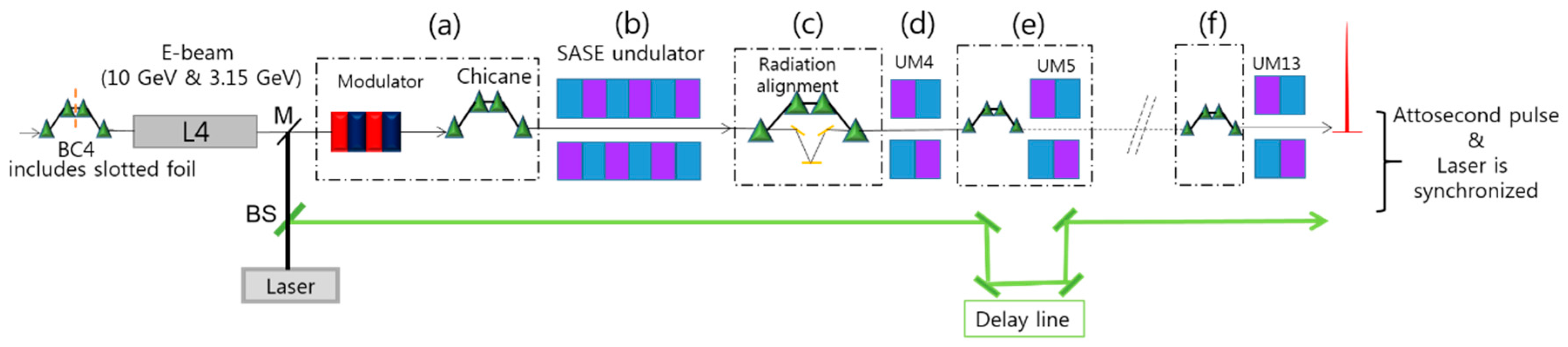
The basic scheme is shown in Figure 1. A slotted foil [27] is inserted in the last bunch compressor section of the PAL-XFEL linac. The foil spoils the electron beam emittance in the head and tail parts of the bunch and suppresses lasing there. Note that the slot is set relatively wide in our scheme because its function is not to shorten the pulse length as in the original proposal but to set a defined temporal window of lasing and define the lasing domain in the electron bunch [29]. The next is the ESASE [20] section that consists of an optical laser, a modulator, and a magnetic chicane for the density modulation of an unspoiled part of the electron beam at the end of a linac section (Figure 1a). In this ESASE section, the electron beam is energy-modulated in a strong magnetic field modulator via the interaction with a co-propagating laser. The shape of the optical cycles of the pulse is replicated in the energy distribution of the electron beam. Later, a magnetic chicane converts the energy modulation to a density modulation so that the flat current profile changes into a profile of current spikes. The electron beam with these current spikes is sent to an undulator (Figure 1b) for radiation generation. The SASE undulator is made by three undulator modules (UMs). The length of the undulator is kept short to avoid saturation and to keep the electron-beam energy spread at a minimum.
Figure 1c represents a chicane–mirror system composed of four dipole magnets and a set of mirrors [36]. The magnetic chicane is used for delaying an electron beam and diluting the microbunching developed in an undulator. A set of reflecting mirrors is used to delay an X-ray pulse with respect to a particular electron spike in the electron beam. The X-ray pulses are delayed in such a way that the leading radiation spike (target pulse) acts as a seed to trailing current spikes (more description below along with Figure 2) [29]. Figure 1d shows the second, even shorter undulator (1 UM only) for a radiation amplification. This undulator is used to amplify the target pulse. For a good amplification, the radiation seed always needs a fresh electron spike. Figure 1e shows a small magnetic chicane followed by a small undulator section (1 UM only). A small chicane is used to create the delay of the electron beam by a laser wavelength λL to align the radiation spike to the next current spike. The same unit shown in Figure 1e is used several times in the downstream undulator for repeated electron beam delays and repeated amplifications of a target pulse to obtain an isolated TW-attosecond radiation pulse at the end.
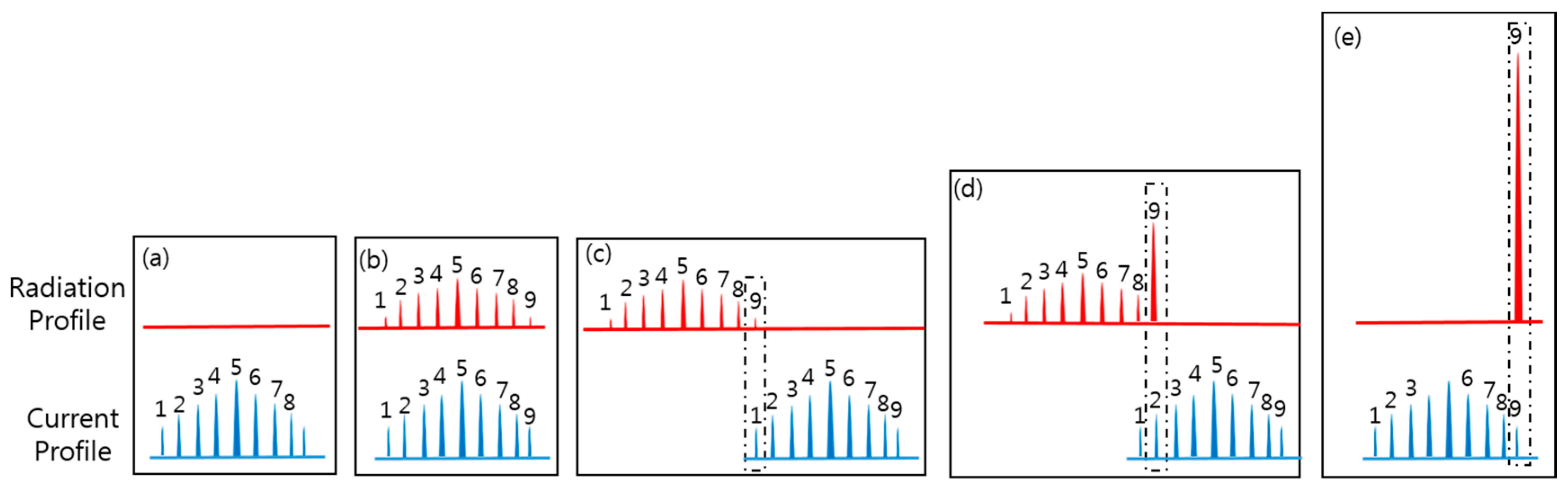
Figure 2 shows the working principle of the scheme. First, Figure 2a shows that a few current spikes with different magnitudes are generated by an optical laser’s interaction with electron beam inside the modulator, followed by a density modulation in a magnetic chicane (see Figure 1a). The separation between the current spikes is in the order of the modulation laser wavelength λL. Figure 2b shows the current and radiation profile after the first stage of amplification (Figure 1b), and the same number of radiation spikes (a total of 9) are generated. Now, in Figure 2c, the 9th radiation spike is selected as a target pulse and aligned with the tail current peak (1st current peak) via a chicane–mirror system (Figure 1c). Figure 2d shows the current and radiation profile after 2 UM amplification. The electron beam is delayed by λL to align the 2nd current spike with the target radiation pulse for next amplification (Figure 1e). This procedure is repeated and the target pulse is aligned sequentially with all the current spikes to yield a solitary TW-attosecond radiation pulse, as shown in Figure 2e, at the undulator exit (Figure 1f).
3. Results and Discussion
We illustrate two cases of TW-attosecond XFEL: one in a hard X-ray regime (12.4 keV or 0.1 nm) and the other in the soft X-ray region (~1 keV or 1.25 nm). To consider a more realistic situation, we use the parameters of Korean XFEL [5].
3.1. Terawatt-Attosecond Hard X-ray Pulse Generation
First, an electron beam with an energy of 10 GeV, a 200 pC bunch charge, an average current of 2.0 kA, 66 fs in length with a normalized emittance of 0.5 mm-mrad, and an un-correlated energy spread of 0.01% is generated using ELEGANT code [37] by taking into account the space-charge effects and the microbunching instabilities [38]. The popular ELEGANT code has been used to track the particle dynamics in six dimensional phase space coordinates.
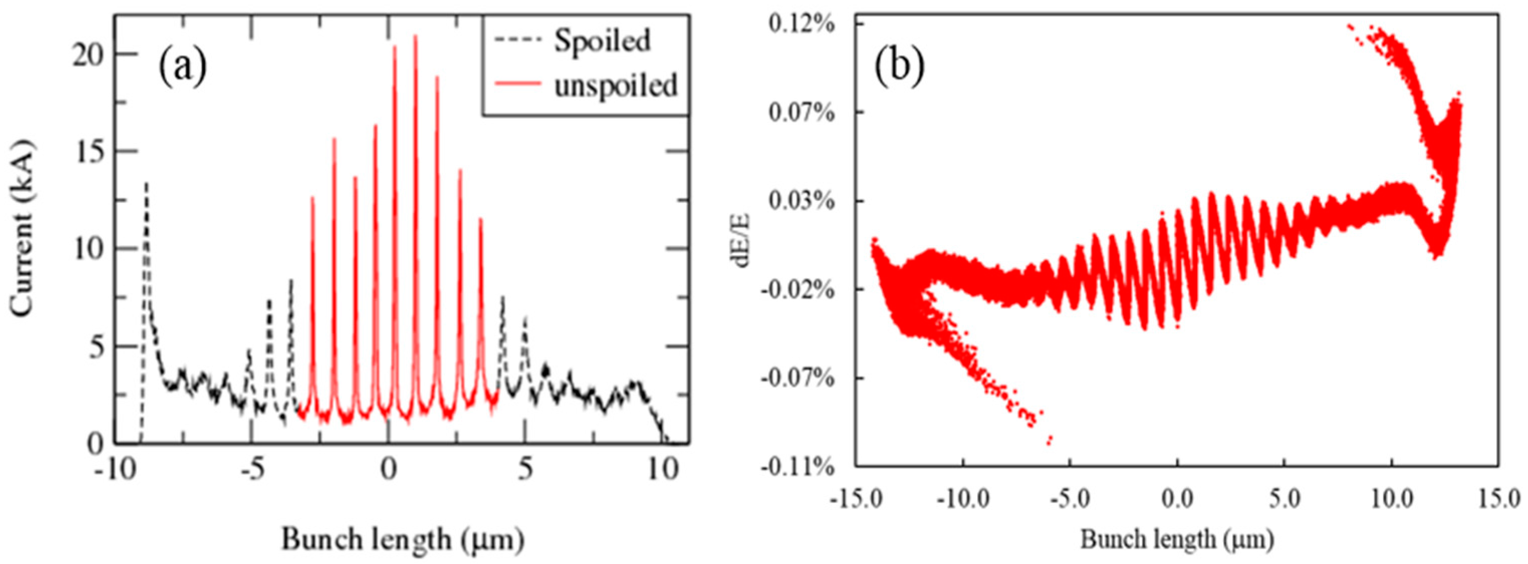
For the energy modulation of an electron beam (Figure 1a), an 800 nm, 30 fs, and 50 GW laser is used inside a two period modulator with a wiggler period of 50 cm; the density modulation is generated by a magnetic chicane with a time-of-flight parameter R56 of ~0.16 mm. The generated current distribution after these two processes is shown in Figure 3a: several current spikes with different magnitudes at an average background current of 2 kA. Figure 3b shows the corresponding plot in the longitudinal phase space after the energy and current modulation of a 10 GeV electron beam. Note that the current spikes are larger by a factor of approximately 8 compared to the background current. Note also that the window for the lasing section of the current profile can be controlled by the slotted foil system [27]. The red line in Figure 3a is the unspoiled section of the electron bunch, which is fed to UMs to generate an X-ray pulse at a photon energy of 12.4 keV. The nine current spikes in total are considered. These spikes radiate strongly in an undulator. Usually, the advantage of operating an FEL with a high peak current is the increase in X-ray output power. However, high current spikes also suffer from the energy spread, which is taken into account in this calculation. In Figure 3b, one can see that the increase in peak currents is accompanied by corresponding increases in the peak–peak energy modulation depth.
Now, the electron beam is sent to UMs to generate an X-ray pulse at a 12.4 keV photon energy. For undulator radiation, simulations are performed using three-dimensional time-dependent FEL code GENESIS [39]. Note that, due to large energy modulation, high peak current spikes suffer from the energy chirp [40] due to short-range and long-range space-charge effects. Short range space-charge effects acting against microbunching have been included in the GENESIS code [39] but the long-range space-charge effect (or longitudinal debunching effect) is overlooked in the simulation code [39]. Here, it is worth acknowledging that according to [41], longitudinal debunching causes a reduction in the peak current of the current spikes during radiation amplification and the reduction is of the order of only a few percents, not significant for high-electron beam energies (i.e., >3 GeV).
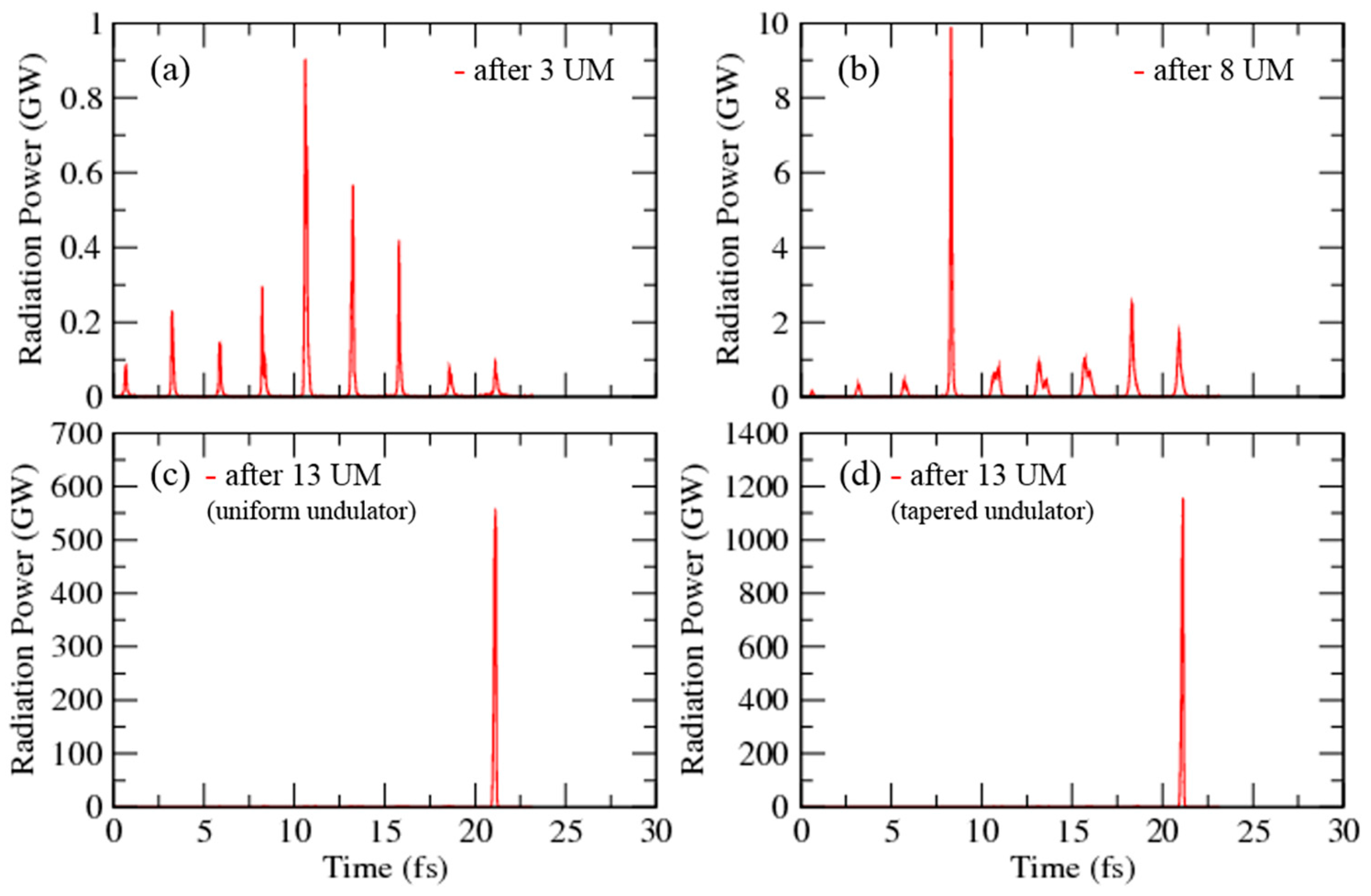
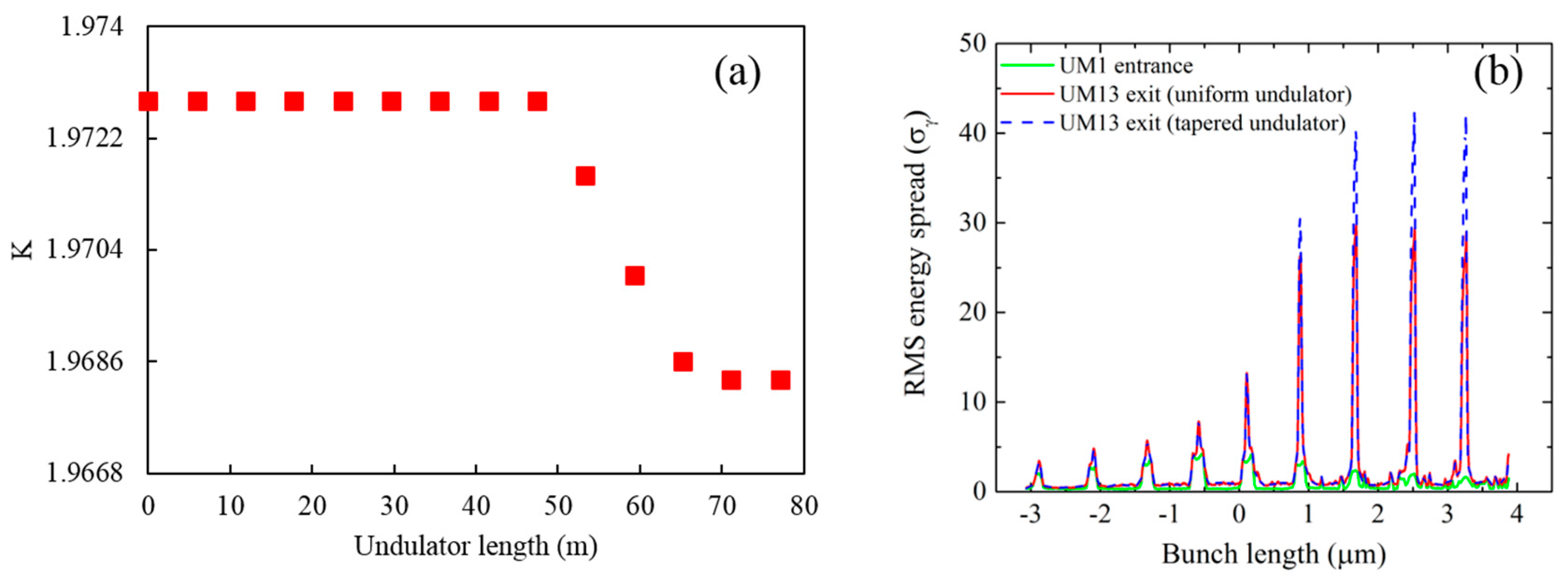
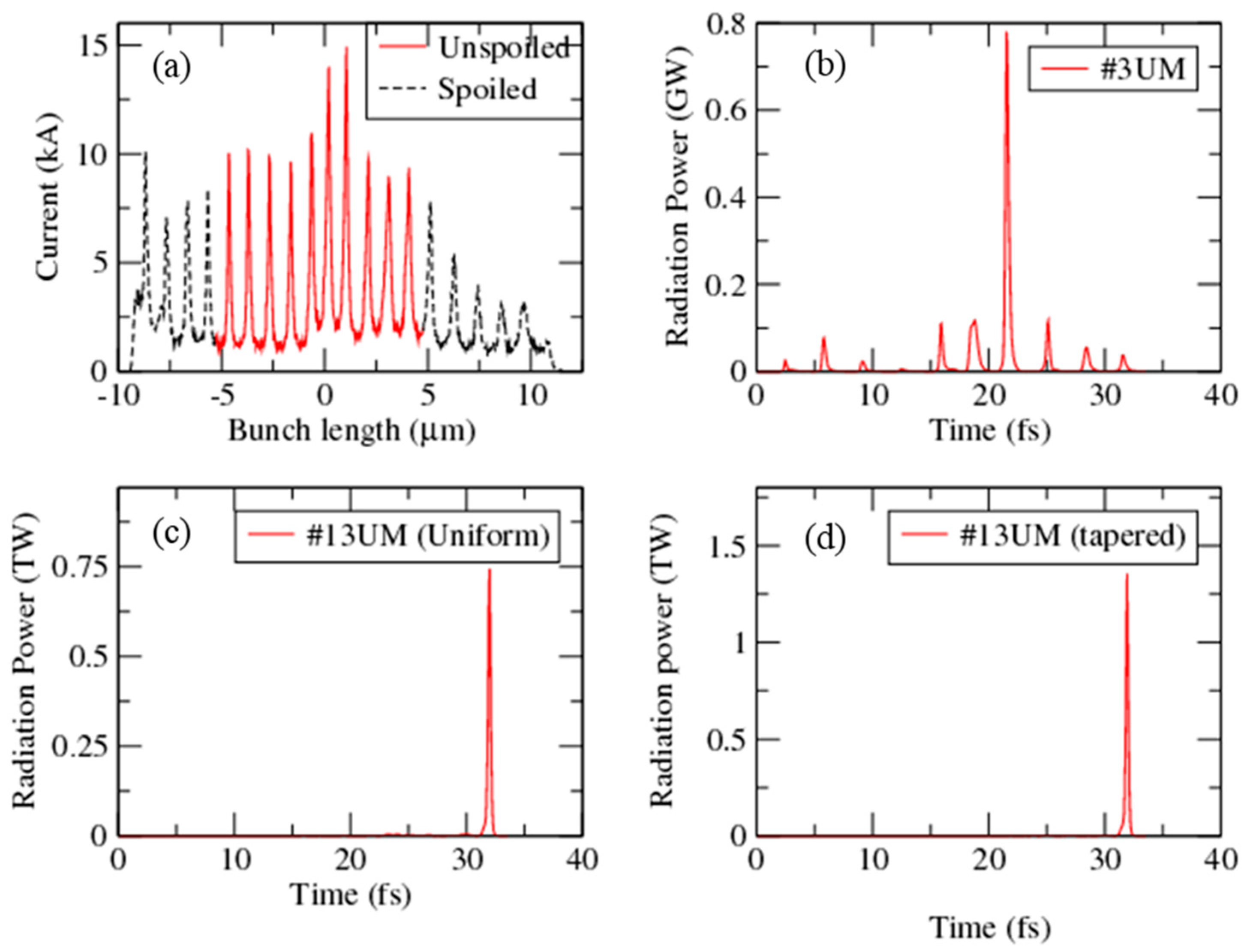
Figure 4a shows the temporal profile of the radiation pulse after the 3rd UM. The first three UMs play a role in generating initial SASE radiation. Each UM is 5 m long with an undulator period of 2.6 cm (Figure 1b). The drift space between two UMs is long enough to accommodate the magnetic chicane used for the electron beam delay. After the first amplification stage, the optical delay is adjusted before the next UM to align the target pulse (i.e., the 9th pulse in the radiation profile) with the tail current spike (i.e., the 1st current spike in the current profile) (Figure 2c). At each of the following amplification stages, the target pulse is aligned with a fresh current spike (i.e., the 2nd, 3rd, 4th, and so on) using the electron-beam delay unit. Figure 4b shows the snapshot of the radiation pulse after 8 UMs. After 8 UMs, we get one dominant radiation spike with a few weak neighboring radiation spikes. The snapshot of the radiation after 13 UMs in a uniform undulator is shown in Figure 4c. After the 13th UM, we obtain a 0.55 TW and 130 attosecond radiation pulse at a photon energy of 12.4 keV in a 75 m long uniform undulator. This power corresponds to 0.1 mJ energy (or 5 × 10¹⁰ photons) per pulse. As the amplification progresses, the resonant condition is gradually broken. The undulator strength parameter K may need to be tapered to maintain the resonance condition as the electron beam loses its energy [35]. Initially, up to 47.4 m long, the energy loss was not severe. Thus, we considered tapering in the last part of the undulator. For each undulator module, K value was optimized to maximize the power. Figure 4d shows the result of tapering optimization: the radiation profile after 13 UMs in a tapered undulator. The radiation power was doubled, up to 1.2 TW, by applying the tapering from UM9 to UM13, within a 75 m long undulator without any other modification.
High peak currents suffer from the energy spread and the major energy loss occurs at the current spikes to which the target radiation spike is seeded. By choosing a tapering to compensate the degradation of the seeded current spike, we preserve the resonance condition in that region and partially suppress the amplification at the neighboring current spikes due to the off-resonance condition. The ideal tapering profile is a smoothly varying function of undulator length. However, a stepwise undulator tapering is considered here along UM9-UM13 modules, maximizing the output power. The stepwise tapering is shown in Figure 5a. First, UM1-UM8 undulator modules have the same parameter . The modules UM9-UM13 belongs to the exponential regime of radiation amplification. Therefore, is adjusted to decrease sharply along the undulator. The undulator parameter of the nth undulator module can be described as
where is the initial undulator parameter, k is the segment number at which the tapering starts, and a and b are the coefficients obtained by multidimensional scans that maximize the radiation power. The optimal values for hard X-ray case are plotted in Figure 5a with = 1.9728 and = 8.
Figure 5b shows the growth of the electron-beam energy spread. The green curve shows the initial energy spread due to the current modulation by the ESASE section prior to the undulator entrance. The red curve shows the growth of the energy spread after 13 UMs in the uniform undulator case and the blue-dotted curve in the tapered undulator case. One can see that some of the current spikes are still reusable due to the small energy spread. Therefore, the radiation power can be further increased if more units are added.
For the robustness of the scheme, the shot noise effect on the X-ray pulse peak power and the pulse duration have been tested. The simulation was performed for 10 different seed values. Figure 6a shows the average power for uniform and tapered configuration. For the tapered undulator system, the average power after 13 UM stage amplification is 0.9 ± 0.2 TW (red curve), while the average pulse duration is 100 ± 15 attosecond FWHM. For the uniform undulator system, the average power is restricted to a maximum of 0.42 ± 0.1 TW.
Figure 6b shows the clean radiation spectrum for both the uniform (black line) and the tapered undulator (red line). For the uniform undulator, the FWHM pulse width is 130 as (inset) and the spectrum bandwidth is 15 eV wide. From the frequency–time bandwidth relation, , the bandwidth turns out to be 14 eV wide. In case of tapered undulator, the pulse width is 115 as, and the spectrum width is 20 eV wide. Using we obtain a bandwidth 15.8 eV wide. These estimates indicate that there is a chirp induced in the amplification. The chirp is larger in the tapered case than in the uniform case. The radiation spectrum of the tapered undulator is slightly broader compared to that of the uniform undulator. This spectral bandwidth increases due to the sideband growth in the tapered undulator case.
3.2. Terawatt-Attosecond Soft X-ray Pulse Generation Tables and Schemes
The generation of attosecond soft X-ray XFEL pulse has also been investigated. In the soft X-ray beamline of PAL-XFEL, the electron beam has an energy of 3.15 GeV with a bunch charge of 200 pC and an average current of 2.0 kilo-ampere (kA). The electron-bunch is 66 fs long with a normalized emittance of 0.3 mm-mrad and an uncorrelated energy spread of 0.01%.
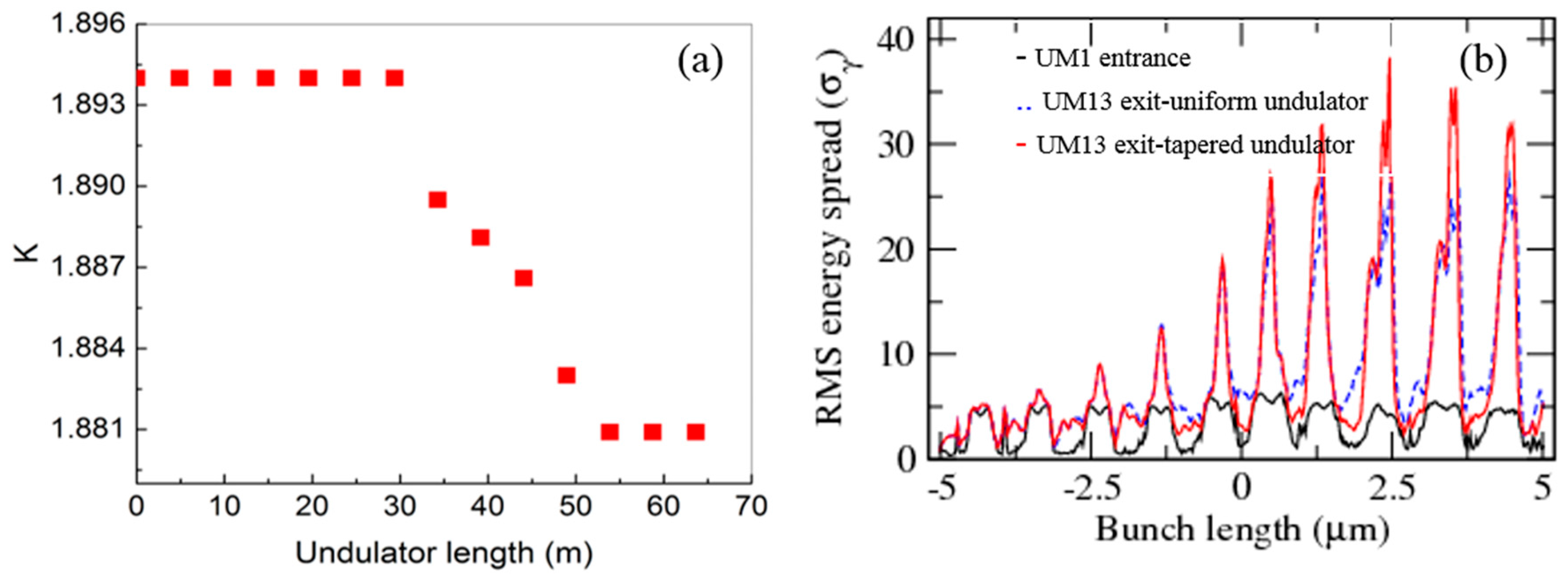
A series of simulations similar to those for the hard X-ray XFEL has been carried out. Figure 7a shows the current distribution after the modulator-chicane section. The black-dotted line represents the spoiled part by a slotted foil, and the central part (red line) shows the unspoiled part of the electron beam, which is chosen for radiation amplification. To generate this comb-like current profile, an optical laser at 1200 nm with a 65 fs pulse duration and 26 GW power is used for energy modulation in electron beam using a two-period modulator of 50 cm wiggler period. For the current modulation, a magnetic chicane of R56 ~0.11 mm is used. In total, 13 UMs are used for amplification. Each UM is 4.9 m long with a 3.4 cm undulator period. Figure 7b shows the temporal profile of the output radiation power after the first 3 UMs. The first three UMs without the delay of the electron beam are optimized, at the expense of radiation power, for minimum energy spread and a short pulse length. Figure 7c shows a solitary radiation pulse of 0.75 TW and 258 attosecond pulse duration in a 60 m long uniform undulator that includes 13 UMs and the drift sections. The radiation power can be increased up to 1.3 TW in a tapered undulator and to a 230 attosecond pulse duration, as shown in Figure 7d. This power corresponds to 0.3 mJ of energy (or 1 × 10¹² photons) per pulse.
A stepwise tapering (Equation (1)) is applied along UM7-UM13 modules of the soft X-ray undulator to maximize the radiation power. Figure 8a shows the tapering of parameter applied along the undulator in the soft X-ray case. Optimal values for the soft X-ray case are as follows: = 1.8940, = 6, and and are optimized by multi scans to maximize the output radiation power. Figure 8b shows the electron-beam energy spread at various places: the black line at the entrance of the undulator, the blue-dotted line at the undulator exit in the uniform undulator, and the red line at the undulator exit in the tapered undulator.
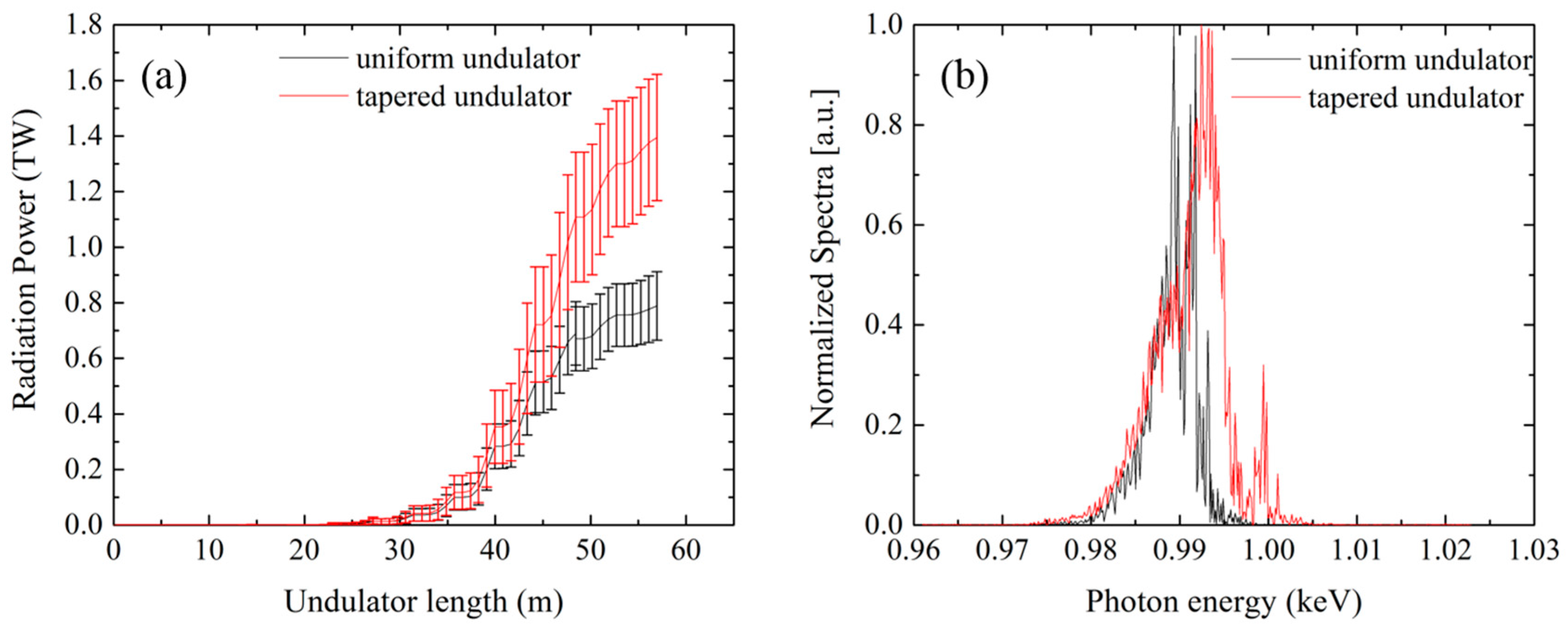
The effect of the electron beam’s shot noise on the peak power of soft X-ray pulse and the pulse length is tested. The simulation was performed for 10 different random seeds, whose results are shown in Figure 9a. The black curve with errors shows the radiation power for 10 different random seeds in a uniform undulator. The average power (black curve) after 13 UM stage amplification is 0.8 ± 0.1 TW, and the average pulse duration is 260 ± 20 attosecond FWHM. Simulations in a tapered undulator show that the average power (red curve and errors) after 13 UM stage amplification is 1.4 ± 0.2 TW, while the average pulse duration is 230 ± 20 attosecond FWHM. From Figure 9a, it is clear that the radiation growth is not saturated even after 13 UMs. Therefore, the radiation power can be further increased if more UMs are added. Figure 9b shows the radiation spectra for a uniform (black curve) and a tapered (red curve) undulator. Note that the radiation spectrum in case of a tapered undulator (red curve) is broader and shows one additional mode due to the tapering of the K parameter.
The realization of X-ray delay is important in this scheme. A soft X-ray mirror typically suffers from transmission losses while hard X-ray Bragg reflectors are only narrow-band, which cannot be applied to this scheme due to the broad-band nature of the radiation spikes [42]. Hence, the design of an X-ray delay unit using grazing incidence geometry has been discussed in detail in [32]. According to [32], a chicane–mirror system using mirrors with a length of 5~6 cm and a deflection angle of 0.1° in grazing incidence geometry would be suitable for obtaining the required optical delay. A similar X-ray delay unit would also be applicable in soft X-ray cases. Moreover, the mirror stages with a 10 nm resolution are commercially available. Therefore, the delay can be controlled with a high degree of precision.
For meaningful pump-probe experiments at the XFEL end stations, the synchronization of the X-ray pulse and optical laser has to be sustained over the full legnth of the experimental configuration including the delay chicanes and other transport optics. Therefore, it is required that all electron beam and optical components are placed onto the same support system. The mechanical vibration leads to the instability in optical path lengths. However, using a feedback loop [43], such an instability can be suppressed and the time delay between pump and probe pulses can be controlled within 20 as RMS. Optical transport of ultrashort pulses generated by optical laser from its optical table to the experimental stations, which are ~100 m away, requires ultra-high vacuum transport system. S. Schulz et al. [44] and P. Cinquegrana et al. [45] have demonstrated that a carefully designed laser beam transport, including a free space propagation of 150 m and a number of beam folding mirrors allows one to keep the timing fluctuations to less than 4 femtoseconds RMS.
4. Conclusions
We have carried out simulations for the hard X-ray beamline (10 GeV e-beam) and for the soft X-ray beamline (3.15 GeV e-beam) of Korean XFEL to assess the performance of the multi-electron spike scheme. The simulation results indicate that an isolated attosecond radiation pulse of 0.6 TW power and a 130 attosecond duration can be achieved at a photon energy of 12.4 keV in a ~75 m long uniform undulator, which can be further scaled up to 1 TW and 115 attosecond duration in a 75 m long tapered undulator. Similarly, in the soft X-ray case, a radiation pulse of 0.75 TW power and 258 attosecond duration can be achieved at a photon energy of ~1 keV (1.25 nm) in a ~60 m long uniform undulator, which can be further enhanced up to 1.35 TW and a duration of 230 attosecond via tapering to a few downstream undulator sections within a 60 m long undulator. We noticed that tapering helps in suppressing the amplification of satellite pulses. Only a target pulse (seed pulse) is amplified due to on-resonance amplification. Moreover, the undulator tapering allows one to achieve a two-fold increase in the peak power within the same undulator length. Additional work on the careful optimization of electron beams, lasing domains, and ESASE parameters may further improve the performance of this scheme in SASE FELs. Such high power and short X-ray pulses will be useful in such research fields as bioimaging, mostly for single-molecule imaging [11], as well as ultrafast science.
Acknowledgments
This research has been supported in part by the Global Research Laboratory Program [Grant No. 2009-00439], by the Max Planck POSTECH/KOREA Research Initiative Program [2016K1A4A4A01922028], through the National Research Foundation of Korea (NRF) funded by Ministry of Science, ICT Future Planning, and by the Nuclear Research Foundation of Korea (NRF) grant funded by the Korea government (MEST) (No. 2012027506). Alexandra S. Landsman acknowledges the support of the Max Planck Center for Attosecond Science (MPC-AS).
Author Contributions
S.K. and D.E.K. conceived and designed the simulation method; S.K. performed the simulations and analyzed the data; S.K., A.S.L. and D.E.K. wrote the paper.
Conflicts of Interest
The authors declare no conflict of interest.
References
- Emma, P.; Akre, R.; Arthur, J.; Bionta, R. First lasing and operation of an angstrom wavelength free-electron laser. Nat. Photonics 2010, 4, 641–647. [Google Scholar] [CrossRef]
- Altarelli, M.; Brinkmann, R.; Chergui, M.; Decking, W. DESY Report; The European X-ray Free Electron Laser: Schenefeld, Germany, 2006. [Google Scholar]
- Ishikawa, T.; Aoyagi, H.; Asaka, T.; Asano, Y.A. Compact X-ray free-electron laser emitting in the sub-angstrom region. Nat. Photonics 2012, 6, 540–544. [Google Scholar] [CrossRef]
- Amann, J.; Berg, W.; Blank, V.; Decker, F.J. Demonstration of self-seeding in a Hard-X-ray free-electron laser. Nat. Photonics 2012, 6, 693–698. [Google Scholar] [CrossRef]
- Ko, I.S.; Han, J.H. Current status of PAL-XFEL. In Proceedings of the 2014, 27th Linear Accelerator Conference, Geneva, Switzerland, 31 August–5 September 2014. [Google Scholar]
- Paul, P.M.; Toma, E.S.; Breger, P.; Mullot, G. Observation of a train of attosecond pulses from high harmonic generation. Science 2001, 292, 1689–1692. [Google Scholar] [CrossRef] [PubMed]
- Hentschel, M.; Kienberger, R.; Spielmann, C.H.; Reider, G.A. Attosecond Metrology. Nature 2001, 414, 509–513. [Google Scholar] [CrossRef] [PubMed]
- Krausz, F.; Ivanov, M. Attosecond Physics. Rev. Mod. Phys. 2009, 81, 163–234. [Google Scholar] [CrossRef]
- Corkum, P.B.; Krausz, F. Attosecond Science. Nat. Phys. 2007, 3, 381. [Google Scholar] [CrossRef]
- Dunning, D.J.; McNeil, B.W.J.; Thompson, N.R. Towards Zeptosecond-scale pulses from X-ray free-electron lasers. Phys. Procedia 2014, 52, 62–67. [Google Scholar] [CrossRef]
- Fratalocchi, A.; Ruocco, G. Single-molecules imaging with X-ray free-electron lasers: Dream or reality. Phys. Rev. Lett. 2011, 106, 105504. [Google Scholar] [CrossRef] [PubMed]
- Goulielmakis, E.; Loh, Z.H.; Wirth, A.; Santra, R. Real-time observation of valence electron motion. Nature 2010, 466, 739–743. [Google Scholar] [CrossRef] [PubMed]
- Geiseler, H.; Rottke, H.; Zhavoronkov, N.; Sandner, W. Real-Time observation of interference between atomic one-electron and two-electron Excittaions. Phys. Rev. Lett. 2012, 108, 123601. [Google Scholar] [CrossRef] [PubMed]
- Fuchs, M.; Trigo, M.; Chen, J.; Ghimire, S. Anomalous nonlinear X-ray Compton scattering. Nat. Phys. 2015, 11, 964–970. [Google Scholar] [CrossRef]
- Neutze, R.; Wouts, R.; Spoel, D.V.D.; Weckert, E. Potential for biomolecular imaging with femtosecond X-ray pulses. Nature 2000, 406, 752–757. [Google Scholar] [CrossRef] [PubMed]
- Inoue, I.; Inubushi, Y.; Sato, T.; Tono, K. Observation of femtosecond X-ray Interactions with matter using an X-ray-X-ray pump-probe scheme. Proc. Natl. Acad Sci. USA 2016, 113, 1492–1497. [Google Scholar] [CrossRef] [PubMed]
- Saldin, E.; Schneidmiller, A.; Yurkov, M.V. A new technique to generate 100 GW-level attosecond X-ray pulses from the X-ray SASE FELs. Opt. Commun. 2004, 239, 161–172. [Google Scholar] [CrossRef]
- Zholents, A.A.; Fawley, W.M. Proposal for intense attosecond radiation from an X-ray free-electron laser. Phys. Rev. Lett. 2004, 92, 224801. [Google Scholar] [CrossRef] [PubMed]
- Saldin, E.L.; Schneidmiller, E.A.; Yurkov, M.V. Self-amplified spontaneous emission FEL with energy-chirped electron beam and its application for generation of attosecond X-ray pulses. Phys. Rev. ST Accel. Beams 2006, 9, 050702. [Google Scholar] [CrossRef]
- Zholents, A.A. Method of an enhanced self-amplified spontaneous emission for X-ray free electron lasers. Phys. Rev. ST Accel. Beams 2005, 8, 040701. [Google Scholar] [CrossRef]
- Zholents, A.A.; Zolotorev, M.S. Attosecond X-ray pulses produced by ultra-short transverse slicing via laser electron beam interaction. New J. Phys. 2008, 10, 025005. [Google Scholar] [CrossRef]
- Xiang, D.; Huang, Z.; Stupakov, G. Generation of intense attosecond X-ray pulses using ultraviolet laser induced microbunching in electron beams. Phys. Rev. ST Accel. Beams 2009, 12, 060701. [Google Scholar] [CrossRef]
- Ding, Y.; Huang, Z.; Ratner, D.; Bucksbaum, P.; Merdji, H. Generation of attosecond X-ray pulses with a multicycle two-color enhanced self-amplified spontaneous emission scheme. Phys. Rev. ST Accel. Beams 2009, 12, 060703. [Google Scholar] [CrossRef]
- Kumar, S.; Kang, H.S.; Kim, D.E. Generation of isolated attosecond hard X-ray pulse in enhanced self-amplified spontaneous emission scheme. Opt. Express 2011, 19, 7537. [Google Scholar] [CrossRef] [PubMed]
- Kumar, S.; Kang, H.S.; Kim, D.E. Tailoring the amplification of attosecond pulse through detuned X-ray FEL undulator. Opt. Express 2015, 23, 2808. [Google Scholar] [CrossRef] [PubMed]
- Chung, S.Y.; Yoon, M.; Kim, D.E. Generation of attosecond X-ray and gamma-ray via Compton backscattering. Opt. Express 2009, 17, 7853–7861. [Google Scholar] [CrossRef] [PubMed]
- Emma, P.; Bane, K.; Cornacchia, M.; Huang, Z. Femtosecond and subfemtosecond X-ray pulses from a self-amplified spontaneous emission-based free electron laser. Phys. Rev. Lett. 2004, 92, 074801. [Google Scholar] [CrossRef] [PubMed]
- Reiche, S.; Musumeci, P.; Pellegrini, C.; Rosenzweig, J.B. Development of ultra-short pulse, single coherent spike for SASE X-ray FELs. Nucl. Instrum. Methods Phys. Res. Sect. A 2008, 593, 45. [Google Scholar] [CrossRef]
- Tanaka, T. Proposal for a Pulse-compression scheme in X-ray free electron lasers to generate a multiterawatt, attosecond X-ray pulse. Phys. Rev. Lett. 2013, 110, 084801. [Google Scholar] [CrossRef] [PubMed]
- Prat, E.; Reiche, S. Simple method to generate terawatt-attosecond X-ray free electron laser pulses. Phys. Rev. Lett. 2015, 114, 244801. [Google Scholar] [CrossRef] [PubMed]
- Prat, E.; Lohl, F.; Reiche, S. Efficient generation of short and high power X-ray free electron laser pulses based on superradiance with a transversely tilted beam. Phys. Rev. ST Accel. Beams 2015, 18, 100701. [Google Scholar] [CrossRef]
- Kumar, S.; Parc, Y.W.; Landsman, A.S.; Kim, D.E. Temporally-coherent terawatt attosecond XFEL synchronized with a few cycle laser. Sci. Rep. 2016, 6, 37700. [Google Scholar] [CrossRef] [PubMed]
- Bonifacio, R.; Souza, L.D.S.; Pierini, P.; Piovella, N. The superradiant regime of an FEL: Analytical and numerical results. Nucl. Instrum. Methods Phys. Res. Sect. A 1990, 296, 358–367. [Google Scholar] [CrossRef]
- Bonifacio, R.; Piovella, N.; McNeil, B.W.J. Superradiant evolution of radiation pulses in a free electron laser. Phys. Rev. A 1991, 44, R3441. [Google Scholar] [CrossRef] [PubMed]
- Kroll, N.M.; Morton, P.L.; Rosenbluth, M.N. Free-electron lasers with variable parameter wigglers. IEEE J. Quant. Electron. 1981, 17, 1436–1468. [Google Scholar] [CrossRef]
- Geloni, G.; Kocharyan, V.; Saldin, E. A simple method for controlling the line width of SASE X-ray FELs. In DESY Report; No. 10-004; Cornell University Library: Ithaca, NY, USA, 2010. [Google Scholar]
- Borland, M. Elegant: A Flexible SDDS-Compliant Code for Accelerator Simulation; Report No. LS-287; Cornell University Library: Ithaca, NY, USA, 2000; pp. 1–11. [Google Scholar]
- Lee, J.H.; Han, J.H.; Lee, S.; Hong, J.; Kim, C.H.; Min, C.K.; Ko, I.S. PAL-XFEL laser heater commissioning. Nucl. Instrum. Methods Phys. Res. Sect. A 2017, 843, 39. [Google Scholar] [CrossRef]
- Reiche, S. GENESIS 1.3: A fully 3D time-dependent FEL simulation code. Nucl. Instrum. Methods Phys. Res. Sect. A 1999, 429, 243–248. [Google Scholar] [CrossRef]
- Geloni, G.; Saldin, E.; Schneidmiller, E.; Yurkov, M. Longitudinal impedence and wake from XFEL undulators. Impact on current-enhanced SASE schemes. Nucl. Instrum. Methods Phys. Res. Sect. A 2007, 583, 228. [Google Scholar] [CrossRef]
- Gruner, F.J.; Schroeder, C.B.; Maier, A.R.; Becker, S.; Mikhailova, J.M. Space-charge effects in ultrahigh electron bunches generated by laser-plasma accelerators. Phys. Rev. ST Accel. Beams 2009, 12, 020701. [Google Scholar] [CrossRef]
- Feldhaus, J.; Saldin, E.L.; Schneider, J.R.; Schneidmiller, E.A.; Yurkov, M.V. Possible application of X-ray optical elements for reducing the spectral bandwidth of an X-ray SASE FEL. Opt. Commun. 1997, 140, 341. [Google Scholar] [CrossRef]
- Chini, M.; Mashiko, H.; Wang, H.; Chen, S. Delay control in attosecond pump-probe experiments. Opt. Express 2009, 17, 21459–21464. [Google Scholar] [CrossRef] [PubMed]
- Schulz, S.; Grguras, I.; Behrens, C.; Bromberger, H. Femtosecond all optical synchronization of an X-ray free electron laser. Nat. Commun. 2015, 6, 5938. [Google Scholar] [CrossRef] [PubMed]
- Cinquegrana, P.; Cleva, S.; Demidovich, A.; Gaio, G. Optical beam transport to a remote location for low jitter pump-probe experiments with a free electron laser. Phys. Rev. ST Accel. Beams 2014, 17, 040702. [Google Scholar] [CrossRef]
Figure 1.
(Color online) Schematic layout for the terawatt (TW)-attosecond X-ray free electron laser (XFEL) [29], (a) ESASE section; (b) SASE undulator; (c) Chicane-mirror system; (d) single undulator module (UM4); (e) a small magnet chicane for e-beam delay followed by single undulator module (UM5); and (f) a small magnet chicane for e-beam delay.

Figure 2.
Working principle of the scheme: the alignment process between the current profile of electron bunch (consisting of nine blue spikes produced by ESASE in Figure 1a) and the radiation profile (consisting of nine red spikes) at different locations of Figure 1.

Figure 3.
(a) The current modulation of a 10 GeV electron beam for hard X-ray amplification; the black-dashed line shows the spoiled section of the current profile and the red-dashed line shows the unspoiled section. (b) The longitudinal phase space plot showing energy modulation of the electrons along the electron bunch after the interaction with the optical laser (Figure 1a).

Figure 4.
The radiation amplification along the undulator for hard X-ray case. Snapshot of the radiation pulse (a) after 3 UMs; (b) after 8 UMs; (c) after 13 UMs in a uniform undulator; and (d) after 13 UMs when a tapering is considered in UM9-UM13. A single isolated 130 attosecond FWHM, 1.2 TW radiation pulse is obtained in a tapered undulator.

Figure 5.
(a) Undulator parameter K for a stepwise tapering, and (b) the electron beam energy spread at the undulator entrance and exit for hard X-ray case.
Figure 5.
(a) Undulator parameter K for a stepwise tapering, and (b) the electron beam energy spread at the undulator entrance and exit for hard X-ray case.

Figure 6.
(a) The average radiation power and the power fluctuations for 10 different random seeds for a uniform and a tapered undulator. (b) Power spectrum of the radiation output for hard X-ray case (inset shows the temporal profiles of the radiation powers).
Figure 6.
(a) The average radiation power and the power fluctuations for 10 different random seeds for a uniform and a tapered undulator. (b) Power spectrum of the radiation output for hard X-ray case (inset shows the temporal profiles of the radiation powers).

Figure 7.
(a) Current modulation of an electron beam of 3.15 GeV energy. The dashed-black line shows the spoiled section, and the red line is the unspoiled section of the current profile. The snapshot of the radiation pulse amplification (b) after 3 UMs; (c) after 13 UMs in a uniform undulator; and (d) after 13 UMs in a tapered undulator.

Figure 8.
(a) Stepwise tapering in the undulator parameter K for the attosecond-TW XFEL in soft X-ray region, and (b) variation of the electron beam energy spread along the undulator.
Figure 8.
(a) Stepwise tapering in the undulator parameter K for the attosecond-TW XFEL in soft X-ray region, and (b) variation of the electron beam energy spread along the undulator.

Figure 9.
(a) The average radiation power for 10 different random seeds along the uniform undulator (black line) and along the tapered undulator (red line) in the soft X-ray case, and (b) the power spectra for the uniform undulator (black line) and for the tapered undulator (red line).
Figure 9.
(a) The average radiation power for 10 different random seeds along the uniform undulator (black line) and along the tapered undulator (red line) in the soft X-ray case, and (b) the power spectra for the uniform undulator (black line) and for the tapered undulator (red line).

© 2017 by the authors. Licensee MDPI, Basel, Switzerland. This article is an open access article distributed under the terms and conditions of the Creative Commons Attribution (CC BY) license (http://creativecommons.org/licenses/by/4.0/).
Share and Cite
MDPI and ACS Style
Kumar, S.; Landsman, A.S.; Kim, D.E. Terawatt-Isolated Attosecond X-ray Pulse Using a Tapered X-ray Free Electron Laser. Appl. Sci. 2017, 7, 614. https://0-doi-org.brum.beds.ac.uk/10.3390/app7060614
AMA Style
Kumar S, Landsman AS, Kim DE. Terawatt-Isolated Attosecond X-ray Pulse Using a Tapered X-ray Free Electron Laser. Applied Sciences. 2017; 7(6):614. https://0-doi-org.brum.beds.ac.uk/10.3390/app7060614
Chicago/Turabian StyleKumar, Sandeep, Alexandra S. Landsman, and Dong Eon Kim. 2017. "Terawatt-Isolated Attosecond X-ray Pulse Using a Tapered X-ray Free Electron Laser" Applied Sciences 7, no. 6: 614. https://0-doi-org.brum.beds.ac.uk/10.3390/app7060614
Note that from the first issue of 2016, this journal uses article numbers instead of page numbers. See further details here.