
Simulation Investigation on Combustion Characteristics in a Four-Point Lean Direct Injection Combustor with Hydrogen/Air

1
Key Laboratory of Aero-engine Thermal Environment and Structure, Ministry of Industry and Information Technology, Nanjing University of Aeronautics and Astronautics, Nanjing 210016, China
2
School of National Defense Engineering, PLA University of Science and Technology, 88 Biaoying Rd., Nanjing 210007, China
3
School of Mechanical Engineering, Purdue University, West Lafayette, IN 47907-2088, USA
*
Author to whom correspondence should be addressed.
Appl. Sci. 2017, 7(6), 619; https://0-doi-org.brum.beds.ac.uk/10.3390/app7060619
Submission received: 5 May 2017
/
Revised: 5 June 2017
/
Accepted: 12 June 2017
/
Published: 14 June 2017
(This article belongs to the Special Issue Clean Energy and Fuel (Hydrogen) Storage)
Abstract
:To investigate the combustion characteristics in multi-point lean direct injection (LDI) combustors with hydrogen/air, two swirl–venturi 2 × 2 array four-point LDI combustors were designed. The four-point LDI combustor consists of injector assembly, swirl–venturi array and combustion chamber. The injector, swirler and venturi together govern the rapid mixing of hydrogen and air to form the mixture for combustion. Using clockwise swirlers and anticlockwise swirlers, the co-swirling and count-swirling swirler arrays LDI combustors were achieved. Using Reynolds-Averaged Navier–Stokes (RANS) code for steady-state reacting flow computations, the four-point LDI combustors with hydrogen/air were simulated with an 11 species and 23 lumped reaction steps H2/Air reaction mechanism. The axial velocity, turbulence kinetic energy, total pressure drop coefficient, outlet temperature, mass fraction of OH and emission of pollutant NO of four-point LDI combustors, with different equivalence ratios, are here presented and discussed. As the equivalence ratios increased, the total pressure drop coefficient became higher because of increasing heat loss. Increasing equivalence ratios also corresponded with the rise in outlet temperature of the four-point LDI combustors, as well as an increase in the emission index of NO EINO in the four-point LDI combustors. Along the axial distance, the EINO always increased and was at maximum at the exit of the dump. Along the chamber, the EINO gradually increased, maximizing at the exit of chamber. The total temperature of four-point LDI combustors with different equivalence ratios was identical to the theoretical equilibrium temperature. The EINO was an exponential function of the equivalence ratio.
1. Introduction
The atmospheric environment is becoming worse, and the environmental protection consciousness of people is stronger than ever. To reduce the effects of the misuse of fossil fuels and their destructive impacts on nature, extensive efforts has been applied to develop hydrogen fuel as an alternative to hydrocarbon fuels [1,2,3,4]. The pollutants produced by the combustion of hydrogen are lower and less damaging than those produced by the combustion of hydrocarbon fuels, therefore, hydrogen could be used as a novel, renewable and environmentally-friendly fuel. The hydrogen fuelled combustion system in operation would mean that there would be no ozone layer depletion, and greenhouse gases and acid rain would be minimised. Hydrogen fuelled combustion of gas turbine engines has huge environmental advantages for the current system, because only water and nitrogen oxides (NOx) are the emissions of hydrogen combustion [5,6]. The hydrogen-enrichment of natural gas could be used to solve several drawbacks encountered for turbulent premixed combustion [7,8,9]. Using the CHEMKIN PREMIX code based on the GRI (Gas Research Institute) kinetic mechanism, the laminar burning velocities in a combustor with hydrogen–methane/air were calculated [10]. The methane reactivity could be enhanced slightly in lean mixtures conditions. Using Time-Resolved Particle Image Velocimetry, Di Sarli [11] investigated the transient interactions of premixed flames and toroidal vortex in combustors with hydrogen-enriched methane/air. The hydrogen presence would increase the main toroidal vortex velocity to affect the flow field and generate different sub-vortices. While the hydrogen substitutes for the methane, the vortex would wrinkle the flame front which induces the small flame pockets separates from the main front. Using a Large Eddy Simulation (LES) method, the unsteady propagation of the premixed flames around toroidal vortices in a combustor with hydrogen-enriched methane/air was simulated [12]. With the hydrogen mole fraction varying from 0 to 0.5 for lean mixtures, good predictions of experimental data could be obtained. The flame shape and structure affected by the vortex were presented. The hydrogen diffusion time was higher than that of the flame roll-up round the vortex.
Hydrogen will be a great potential surrogate for fuel fossil fuels for gas turbine engines in the future, but currently, it is not widely used for gas turbine engines. Previous research on the application of hydrogen focused on internal combustion engines. For example, hydrogen has been seen as suitable for spark ignition engines as fuel, and compression ignition engines are also now in the process of modification to operate with hydrogen [2]. There are only sporadic studies of hydrogen applications for gas turbine engines. Daniel [13] investigated a low emission combustor using hydrogen lean direct injections. At an inlet temperature of 588 to 811 K and inlet pressure of 0.4 to 1.4 MPa, the NOx emissions and combustion performance were measured, and the equivalence ratios were up to 0.48. With multiple injection points and quick mixing, all the injectors were installed to achieve lean direct injection (LDI) technology.
The combination of nitrogen dioxide (NO2) and nitric oxide (NO) is usually called as NOx. The formation of photochemical smog, acid rain and harmful ozone is caused by such NOx emissions as from aircraft engines [14,15]. For fuelled hydrogen gas turbine engines, low NOx emissions of combustion are usually required in order to meet the demand of environmental emissions regulations. The temperature, mixedness, residence time, and engine operation pressure would play an important role in NOx emission production. For designing advanced gas turbine combustors in the future, locally leaner combustion should be developed to achieve low NOx emissions [16,17,18].
Because there is an exponential correlation between the NOx emissions and local combustion temperature, the local temperature peaks and NOx emissions could be reduced through decreasing the burning zone equivalence ratio (below stoichiometric values). There are several low emission combustion technologies, such as lean prevaporized premixed (LPP) combustion [19,20,21], rich quench lean (RQL) combustion [22,23,24,25,26], and lean direct injection (LDI) combustion [27]. Compared with traditional designs, the LDI combustion concept has received considerable attention as an extremely promising technology that utilizes rapid mixing of fuel-air to produce lean combustible mixtures, as well as reduce NOx emissions from the gas turbine engine. LPP combustion technologies could reduce the NOx emission from gas turbine engines, but there are some shortcomings of autoignition and flashback problems for LPP combustor, so that the ignition delay times of the kerosene fuels is shorter when the kerosene is at high pressure and in high temperature conditions [28]. Using multiple smaller assemblies to produce an injector/swirler assembly, rapid mixing could be achieved. Then, multiple small burning zones would be produced. To promote reduced NOx formation, a rapid mixing process, a uniform fuel air mixture, and a short residence time in high temperature zones, are generally best [29]. The evolution of LDI technologies for combustor design was summarized by the authors of [30,31]. To define and refine the next-generation and look for a tool to provide guidance, the combustion characteristics in multi-lean direct injection combustors were investigated with the National Combustion Code (NCC). The different vane angles swirlers were used to form a 3 × 3 element array LDI combustor. Using experimental data, the predictions of CO emission index, NOx emissions index and lean blowout were verified for two different geometry configurations [32]. To gather experience for the next-generation LDI-2, the non-reacting and reacting flow computation method was used to simulate the LDI-2 combustor, which consists of thirteen-element injectors. The NCC includes an approach of spray-modeling, mesh-refinement, kinetics-modeling and ignition. The emissions predictions of EINOx, the emission index of CO (EICO) and the unburned hydrocarbon (UHC) were evaluated for LDI-2 [33]. A parameterized model of swirl–venturi LDI was used to explore a design method [34]. The Reynolds-averaged Navier–Stokes equation for steady-state reacting computations was used to simulate the 20 three-element LDI combustor. The 18-step Jet-A reduced reaction mechanism was used to directly solve the species concentrations of combustion in the LDI combustor. The axial flow field would be vulnerable to the geometric perturbations. The turbulent kinetic energy, axial velocity, fuel distribution, static temperature and species mass fractions were analyzed. At inlet temperatures between 835 and 865 K and inlet pressure of 1034 kPa, the emission of 9-point swirl–venturi LDI (SV-LDI) was measured [35]. The two swirler blade angles were 45° and 60°, respectively. The NOx emissions of LDI with 45° swirler was lower than that of the LDI with 60° swirler. The swirling flow field characteristics of the multipoint LDI combustor with nine fuel injectors were also investigated [36]. Using an injector, an axial swirler and a convergent–divergent venturi, the fuel/air rapid mixing and a recirculation zone for a stabilized flame were achieved. The vane angle of each swirler was 60° and the swirl number was 1.0. The transient swirling flow field structure, the component of velocity and Reynolds stresses were measured by a 3D Particle Image Velocimetry (PIV) system. If the recessed center swirler arrays of LDI combustor are different, the flow structures are significantly different. For both co-swirler LDI combustor and counter-swirler combustor, the short strong central recirculation zones are produced. For the baseline arrays LDI combustor, the turbulent activity near the swirler exit was highest. In a self-sustaining combustion oscillations combustor, the thermoacoustic coupling was observed [37]. The oscillation amplitude was highest when the equivalence ratio was highest. The oscillation strength was affected slightly by the different fuel distributions, whereas the overall equivalence ratio was constant. The proper orthogonal decomposition (POD) was used to present the energetic spatial components that could represent OH* distribution and periodic variation. The fluctuation location and magnitude could be visualized by the POD modes. There were similar phases and locations between OH* variations and periodic changes. A multipoint lean direct injection combustor, which includes 36 fuel injectors and fuel-air mixers was investigated [38]. The construction consists of the injectors, swirlers and fuel distributer, where Jet-A was used as the fuel. The effects of inlet total temperature, inlet total pressure, and equivalence ratio on the NOx emission were investigated when the inlet temperatures and inlet pressures could reach up to 866 K and 4825 kPa. The spray combustion characteristics of a multi-point LDI combustor was investigated [39]. The RANS code was used to simulate the flow and combustion characteristics in the combustor. Using several spray sub-models for the liquid spray modeling, the spray properties were analyzed and discussed. The short flames from individual injectors, a uniform temperature profile at the chamber exit and the uniformly low temperature distribution inside the combustor were observed. The flow field at the injector exits becomes highly strained when the air flow velocity is increasing. The injector structure, rapid mixing, reacting, and operating cycle conditions would affect the performance, operability, and emission of the combustor.
The swirl–venturi four-point lean direct injection combustor with hydrogen/air is explored and the influence of key geometric, swirl–venturi array and equivalence ratio on reacting flow and emission production characteristics is discussed. A swirl–venturi 2 × 2 array four-point LDI combustor has been designed. The injector, swirler and venturi together govern the rapid mixing of hydrogen and air to form a combustible mixture. Using the clockwise swirler and anticlockwise swirler, the co-swirling and count-swirling swirler arrays of LDI combustors were achieved. With the Reynolds-averaged Navier–Stokes code for steady-state reacting computations, the four-point LDI combustors with hydrogen/air were simulated with a reduced 23-step reaction mechanism. The axial velocity, swirl number, velocity angle, effective area, total pressure drop coefficient, total temperature, mass fraction of OH and emission of pollutant NO of a hydrogen fuelled four-point LDI combustor, with different equivalence ratios, were achieved and discussed.
2. Problem Formulation
2.1. Parametric Geometry Definition of Four-Point LDI
Using a parametric modeling scheme, a swirl–venturi 2 × 2 array LDI combustor was produced and is shown in Figure 1. The scheme consists of inlet, injector, swirl–venturi array, combustion chamber. The swirlers include the CW swirler with clockwise vanes and ACW swirler with anticlockwise vanes. There are two swirlers arrangements in LDI combustors, which are the co-swirling array combustor, and the counter-swirling array combustor, as shown in Figure 2. All swirlers of the co-swirling array are in the same swirling direction. The adjacent swirlers of the counter-swirling array have an alternating swirl direction. The dimensions of swirler and venturi modules are shown by the authors of [40]. The width of the four-point LDI combustor has been changed to 82.18 mm, and the length of the four-point LDI combustor is also 300 mm.
2.2. Computational Approach and Modeling
Reynolds-averaged Navier–Stokes code for steady-state reacting computations was used to investigate the flow and combustion characteristics of the four-point LDI combustor [40,41,42]. The conservation equations of mass, momentum, energy and species mass are expressed for steady flow as:
where,, and represent density, fluid velocity vector and flow mass through control volume, and represent static pressure and all the power on the elemental volume; , and represent effective coefficients of heat conduction, diffusion mass of species and reaction heat and other volume heat source; , , and represent mass fraction, diffusion flux, net generation rate and extra generation rate by source defined by dispersed phase and user for species , respectively.
In this paper, the realizable closure turbulence model is considered to solve the turbulence problem of the four-point LDI combustor. The equations of turbulent kinetic energy K and turbulent dissipation could be written as
where, is turbulent kinetic energy generated by the average velocity gradient, is turbulent kinetic energy generated by buoyancy. The and could be written as
where, , , and are the constants of 1.44, 1.9, 1.0 and 1.2, respectively.
By solving the RANS equations coupled with the chemistry, the numerical simulations of the combustion process in the four-point LDI combustor induced by the flame for the H2/Air mixture were performed. The eddy dissipation concept (EDC) combustion model [40,43] was used to solve the interaction of the turbulence and chemistry. The reaction consists of two processes. One of these processes is that the reaction is induced by collision in turbulence micro-scale structure which is controlled by chemical kinetics. The other process is that the mixing time is more than the reaction time in the vortex clouds and the reaction rate is governed by the mixing rate. The H2/Air reaction mechanism is a reduced mechanism which consists of 11 species (H2, O2, OH, H2O2, HO2, H2O, H, N, NO, O, N2) and 23 lumped reaction steps [40,44,45,46,47]. A splitting operator method was used to separately treat the aerodynamic process and the chemical process in the LDI combustion simulation.
2.3. Mesh Generation and Boundary Condition
Simplified computational domains for co-swirling and count-swirling four-point LDI combustors were modeled respectively. Using the commercial gambit software, the unstructured tetrahedral volume grids were generated and are shown in Figure 3. Using a multi-block approach, the meshes of the flow domain for the inlet passages, seven vanes passages of swirlers, the venturi and the dump were refined to ensure uniform grid quality control. The hexahedral cells are used for each vane passage and jet holes of the injector and the mesh size was identical. To reduce computing time and memory spaces of workstation, the appropriate minimum grid quantity was pursued. Therefore, the grid-sensitivities for single and four-point LDI combustors with non-reaction flow were investigated, as shown in Table 1. Compared with the effective areas of simulation and experiment results, the error of all the cases are the range of ±3.6%, which indicates that the computation grids for single and four point LDI combustors are feasible. For the single LDI, the computation grids with 2.2 million cells were an appropriate minimum grid quantity. Based on the computation grids of single LDI, the computation grids with 6.266 million cells and 6.265 million cells were acceptable meshes for co-swirling and count-swirling four-point LDI combustors, respectively.
The inflow boundary condition of the four-point LDI combustors includes an airflow mass-flow rate (min), fuel mass-flow rate (mf) and inlet temperature (Tt3). An outflow boundary was set for the exit. Table 2 lists the boundary conditions for the four-point LDI combustors computation, in which min-1 and min-2 represent the airflow mass-flow rate of the single-element LDI combustor and four-point LDI combustor, respectively. The inlet temperature and operating pressure (P3) are constant for valid comparison. The airflow mass-flow rates of the four-point LDI combustors are four times that of the single-element LDI combustor. The fuel mass-flow rates vary with different equivalence ratio.
3. Results and Discussion
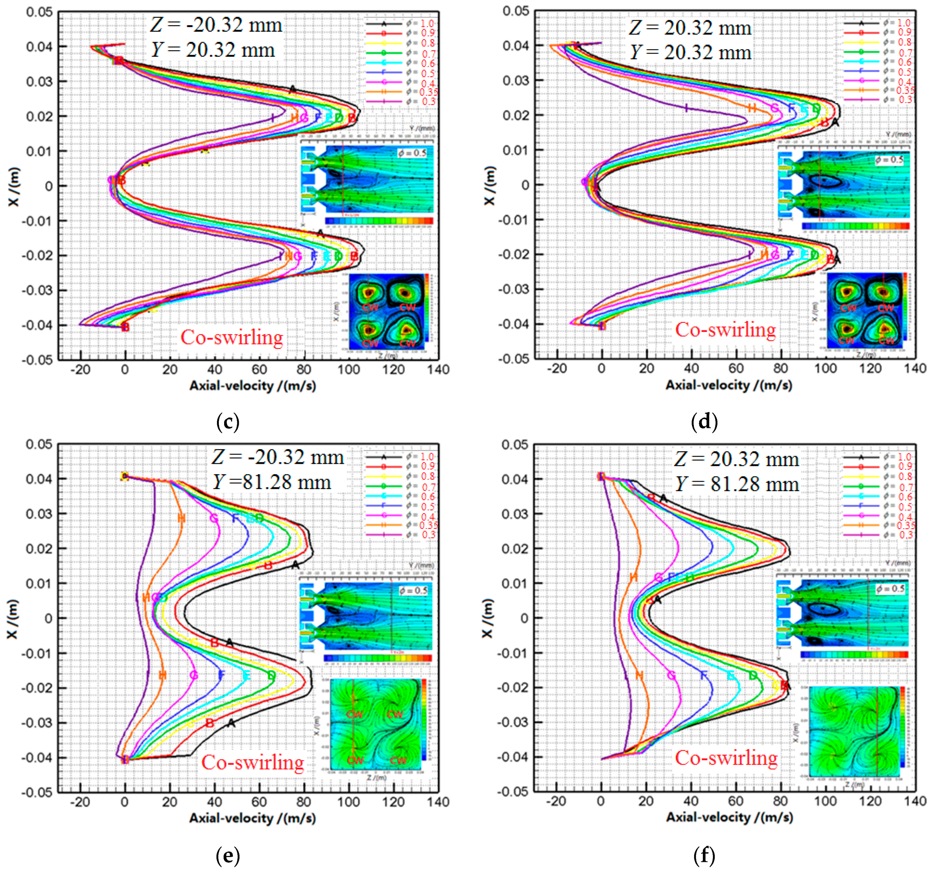
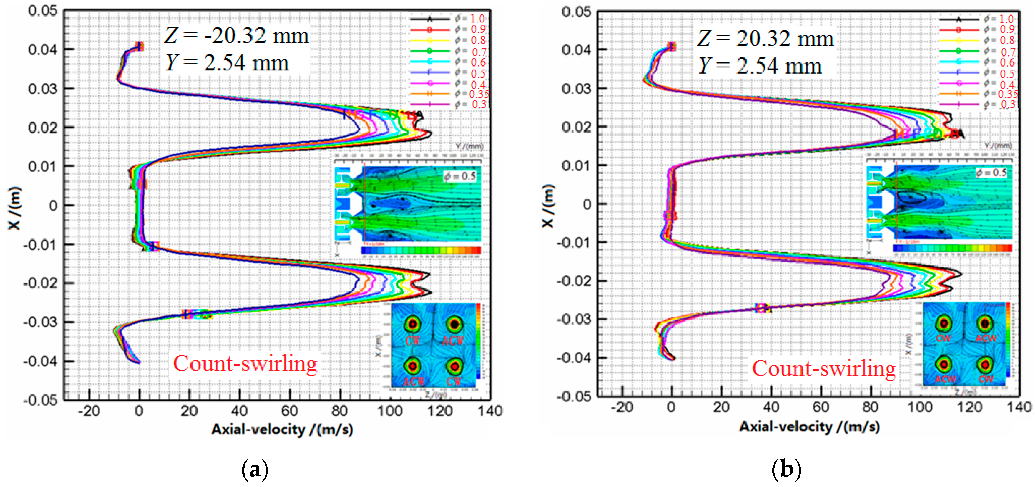
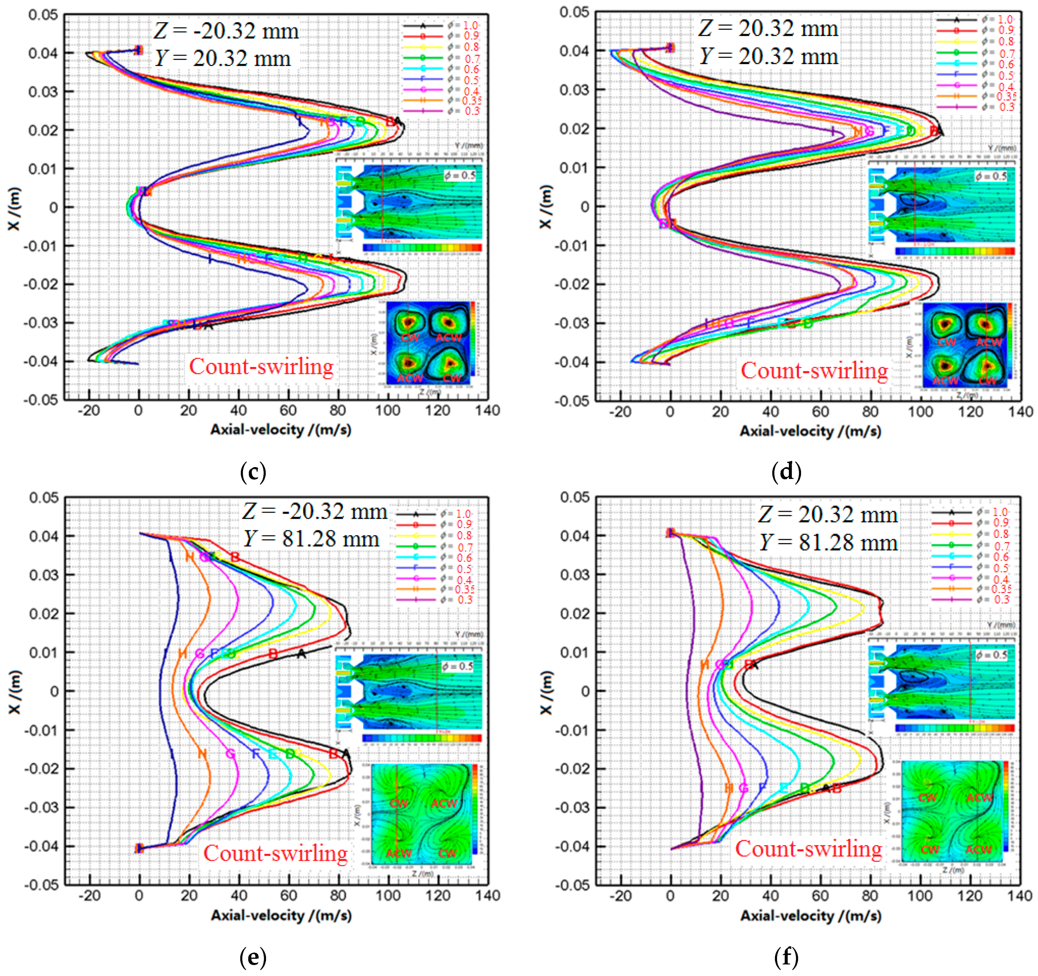
The co-swirling and count-swirling four-point LDI combustors with different equivalence ratios (0.3–1.0) were simulated with H2/Air skeletal and reduced reaction mechanism. The flow and combustion characteristics of the four-point LDI combustors are now discussed. Figure 4 and Figure 5 show axial velocity profiles in line, crossed with two planes, which are the center plane through the axis and the axial planes located at 2.54 mm, 20.32 mm, 81.28 mm, namely Z = −20.32 mm plane, Z = 20.32 mm plane, Y = 2.54 mm plane, Y = 20.32 mm plane, Y = 81.28 mm plane. Axial velocity profiles and contours present that the flow field of each swirler centerline is slightly asymmetrical. There are two asymmetrical recirculation zones near the two side walls of the combustion chambers. There are four interaction vortexes between four array swirlers. Axial velocity profiles are double-peak shaped which looks like a hump. Through reducing the fuel mass-flow rate to decrease the equivalence ratio, the axial velocities along the centerline are decreased. The axial velocity distribution is irregular and presents in a three-dimensional shape. The axial velocities are highest along the centerline of the combustion chamber. The fuel and airflow would be in the center of the combustion chamber which is induced by the velocity distribution. The distribution would result in the flame and high temperature zone being lengthened and moved backward.
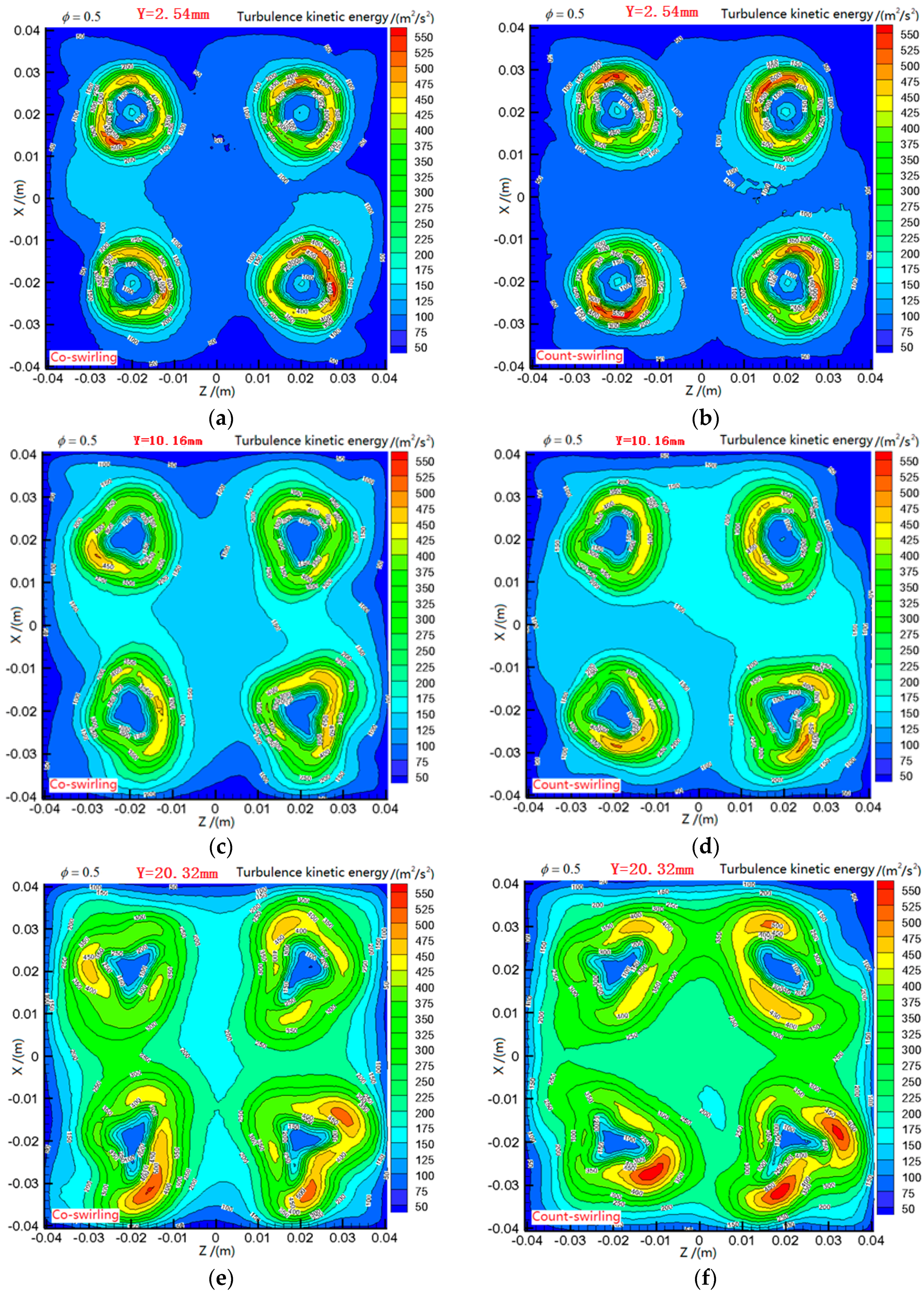
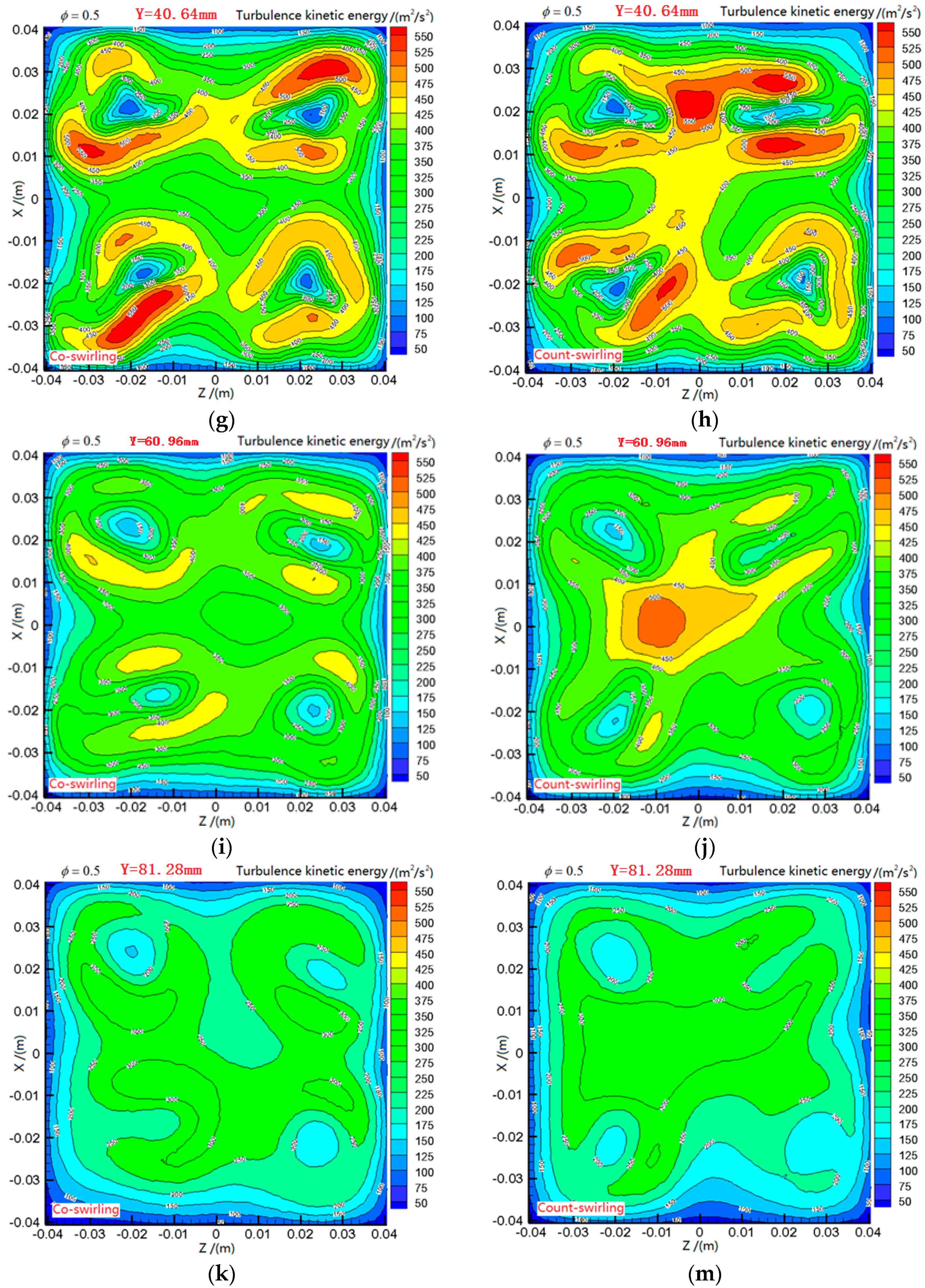
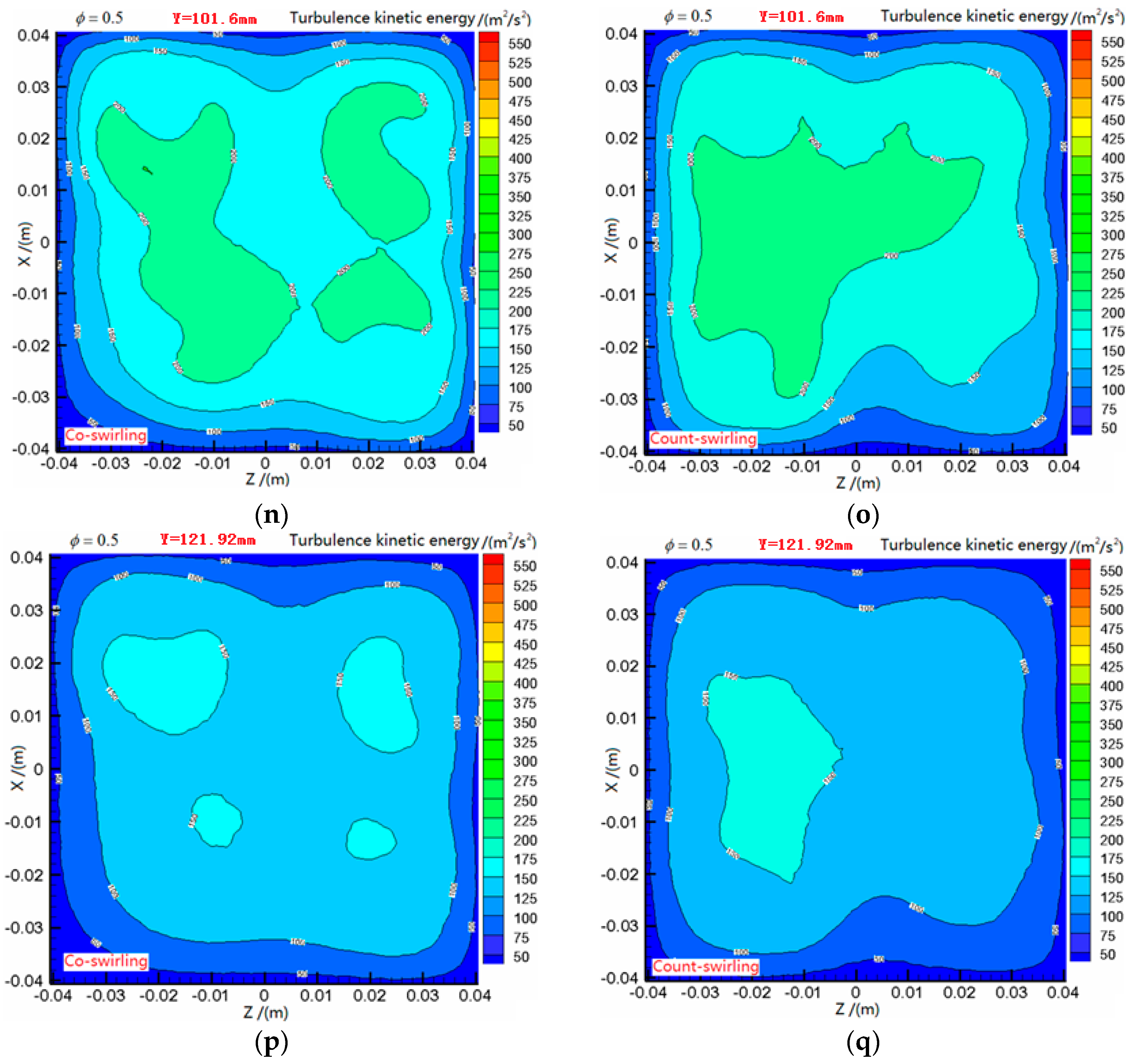
Figure 6 shows the turbulence kinetic energy contours of the co-swirling and counter-swirling four-point LDI combustors with an equivalence ratio of 0.5. There is no interaction between swirler–venturi at Y = 2.54 mm plane of co-swirling and count-swirling four-point LDI combustors. The individual flow field of each swirler–venturi is presented, respectively. The turbulence kinetic energy is highest at swirling flow fan of four-point LDI combustors. While at Y = 10.16 mm plane of co-swirling and count-swirling four-point LDI combustors, the interaction of turbulence kinetic energy between the four swirlers begins to emerge and the intensity of the count-swirling LDI combustor is slightly more than that of the co-swirling LDI combustor. For co-swirling and count-swirling four-point LDI combustors, the interaction of flow field between the four swirlers could be neglected before Y = 10.16 mm plane, only there are interaction effect in downstream flow field. While at Y = 20.32 mm plane of co-swirling and count-swirling four-point LDI combustors, the interaction of flow field between the four swirlers increases. The interaction of co-swirling LDI combustor is obviously less than that of the count-swirling LDI combustor. With the swirling flow running downstream, there is acute interaction effect between the swirlers of the four-point LDI combustor at Y = 40.64 mm and the turbulence kinetic energy is highest at the interface of the swirlers. The turbulence kinetic energy of count-swirling four-point LDI combustor is higher than that of the co-swirling four-point LDI combustor. This indicates that the count-swirling is available to improve the rapid mixing for combustion. When at Y = 60.96 mm of four-point LDI combustors, the highest turbulence kinetic energy locates at the center of the LDI combustor; this is because the spinning air from swirlers are colliding in the center of the count-swirling four-point LDI combustor. When at Y = 81.28 mm of four-point LDI combustors, the turbulence kinetic energy contours of the co-swirling four-point LDI combustor and the count-swirling four-point LDI combustor begin to be uniform and the turbulence kinetic energy also decreases. When at Y = 101.6 mm of four-point LDI combustors, the turbulence kinetic energy is further weakened and tending toward uniformity. The turbulence kinetic energies of the co-swirling four-point LDI combustor and the count-swirling four-point LDI combustor are completely uniform. The different swirler arrangements for the four-point LDI combustors would result in there being different distributions of turbulence kinetic energy. This would affect the fuel-air distributions of the primary combustion zone to induce the temperature difference, which is a disadvantage for reducing the NO emission.
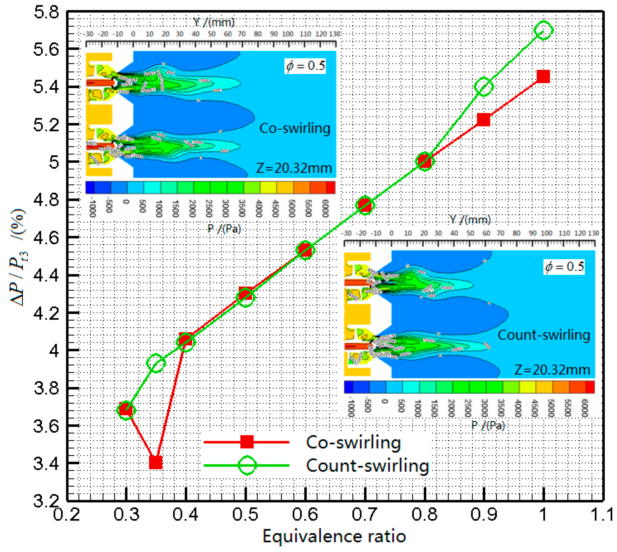
Figure 7 shows the pressure drop coefficients of co-swirling and count-swirling four-point LDI combustors with different equivalence ratios. With the equivalence ratio increasing, the static temperature in the combustion chamber would also be increased, which results in increased velocity, which in turn, increases the total pressure loss. In other words, the pressure drop coefficients of co-swirling and count-swirling four-point LDI combustors are different with different equivalence ratio.
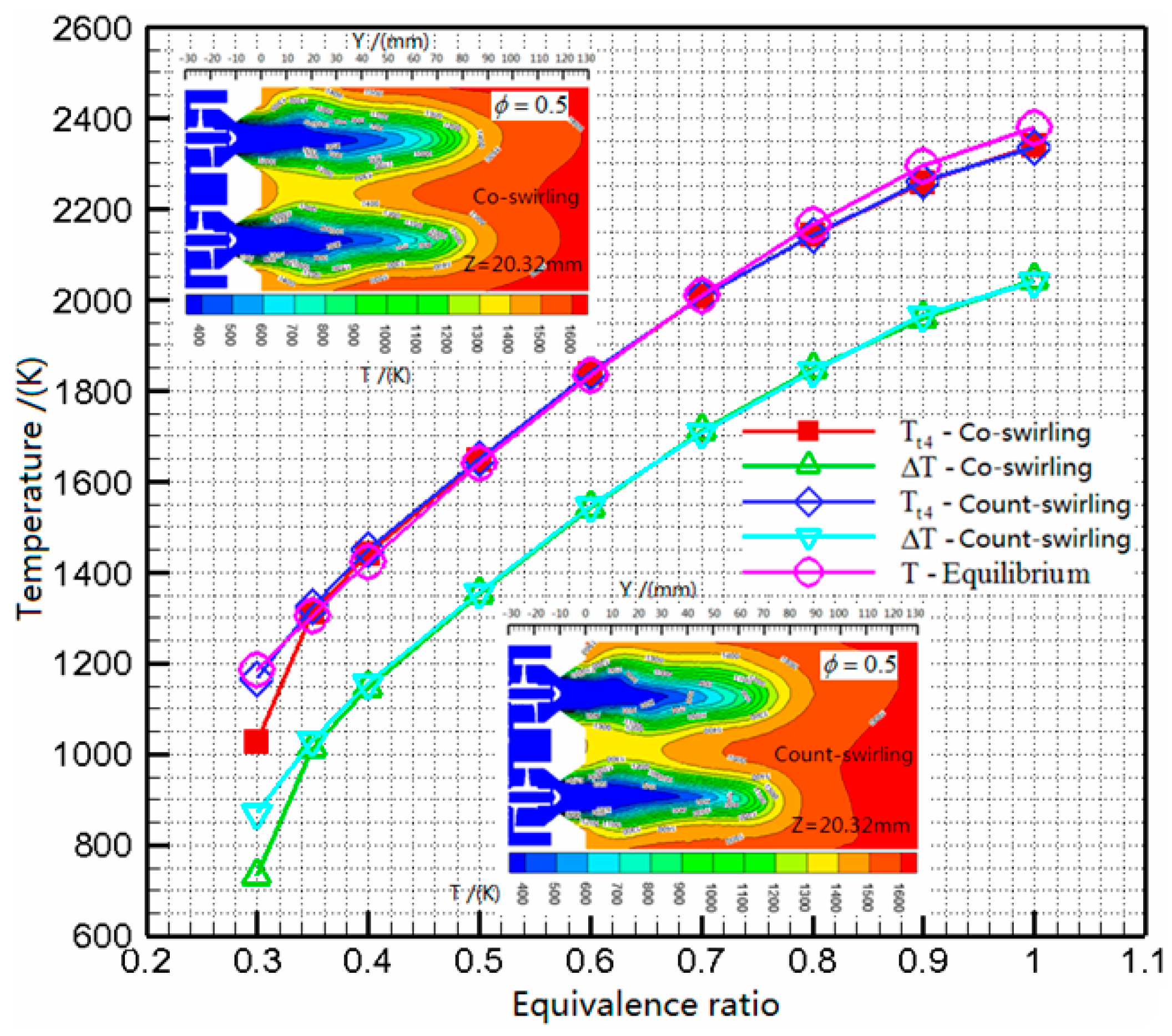
The total temperature profiles of co-swirling and count-swirling four-point LDI combustors with different equivalence ratios are shown in Figure 8. The total temperatures of co-swirling and count-swirling four-point LDI combustors with different equivalence ratios are identical to the theoretical equilibrium temperature. This tendency verified the validation of the numerical methods and codes. When the equivalence ratio is from 0.3 to 1.0, the total temperature increases in the co-swirling and count-swirling four-point LDI combustors, with the increasing of the equivalence ratio. The temperatures of co-swirling and count-swirling four-point LDI combustors increase at approximately same rate. When the equivalence ratio is from 0.3 to 1.0, the temperature rise is from 1150 K to 2050 K. This indicates that hydrogen could serve as fuel for high temperature rise combustors, if the security of storage can be solved easily.
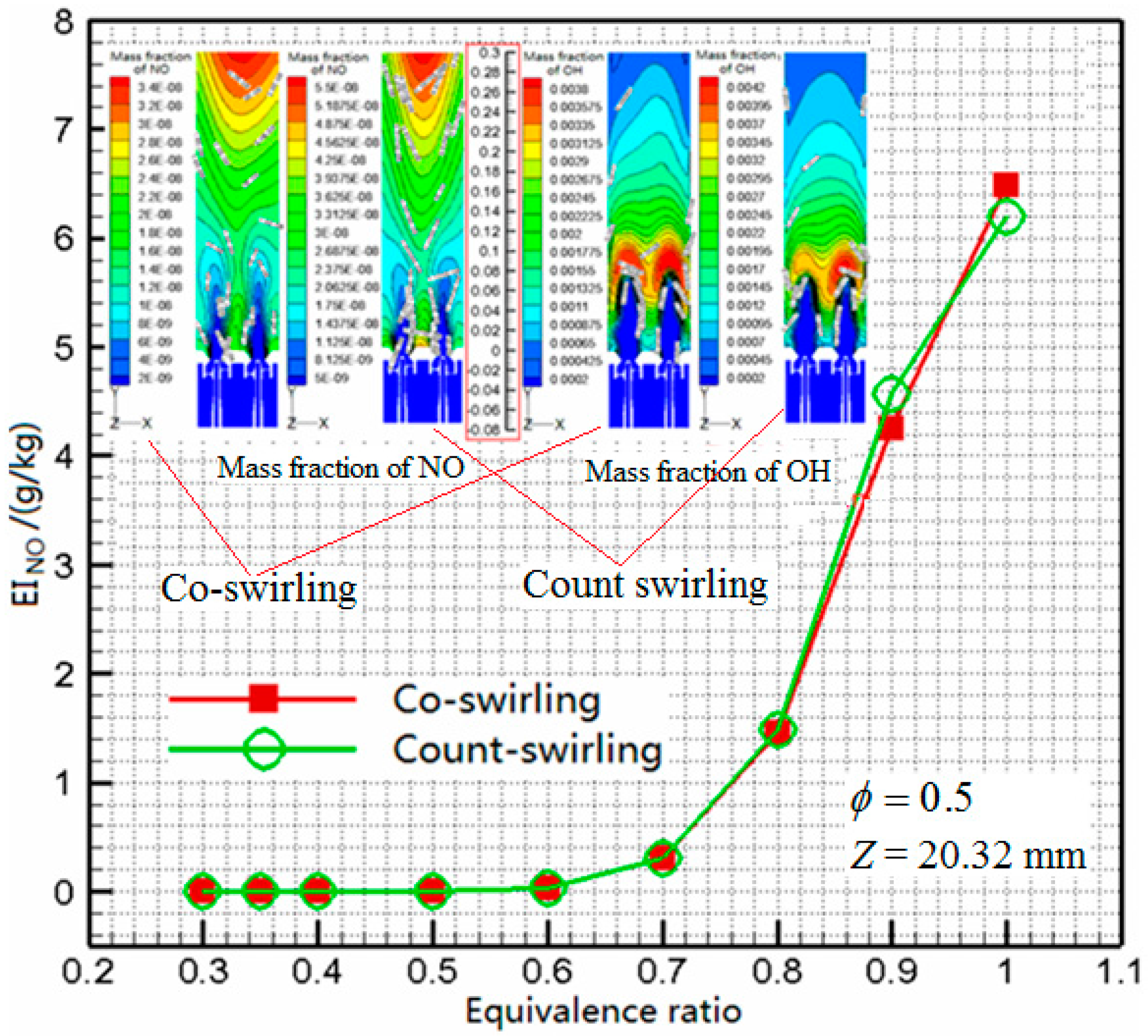
Figure 9 shows the EINO profiles of co-swirling and count-swirling four-point LDI combustors with different equivalence ratios. With the equivalence ratio decreasing, the EINO are reduced sharply in the four-point LDI combustors with the equivalence ratio from 0.6 to 1.0. Corresponding to equivalent ratio of 0.6, the total temperature is approximately 1800 K. Therefore, the tendency of EINO is in line with the formation mechanism of thermal NO [42,43] which is directly related to temperature when the combustion temperature is more than 1800 K. This verifies the validation of the formation model of NO for numerical simulation. While the equivalence ratio is less than 0.6, the EINO value is very low and the mass fraction of NO is very small.
Figure 8 and Figure 9 show the total temperature and EINO contours in the co-swirling and count-swirling four-point LDI combustors with the equivalence ratio of 0.5. For co-swirling and count-swirling four-point LDI combustors, the high temperature zones are all at the rear of combustion chamber, and the formation of NO occurred there, not near the flame at the middle of the combustion dump. This indicates that the reaction rate of H2/Air is more than the formation rate of NO. Along the chamber, the EINO increases gradually, maximizing at the exit of chamber.
4. Conclusions
In this computational study, co-swirling and count-swirling four-point LDI combustors were produced and combustion characteristics in t LDI combustors with hydrogen/air were explored. Using Reynolds-averaged Navier-Stokes code for steady-state reacting computations, co-swirling and count-swirling four-point LDI combustors were simulated with a reduced 23-step hydrogen/air reaction mechanism. The axial velocity, total pressure drop coefficient, total temperature and emission of pollutant NO were presented and discussed. Pressure drop coefficients of co-swirling and count-swirling four-point LDI combustors with different equivalence ratio were observed. The flow field indicates that there existed some degree of flow asymmetry along each swirler centerline and the asymmetrical recirculation zones were produced near the two side walls of the combustion dump. The shape, location and length of the two asymmetrical recirculation zones changed with the decrease of equivalence ratio. The total temperature increased rapidly at the axial distance, and then increased slowly to the theoretical equilibrium temperature. The high temperature zones were all at the rear of the combustion chamber where the formation of NO took place. Along the chamber, the EINO increased gradually and maximized at the exit of the chamber. The total temperatures of co-swirling and count-swirling four-point LDI combustors with different equivalence ratios were identical to the theoretical equilibrium temperature. As the equivalence ratios increase, the total temperatures and temperature rises of co-swirling and count-swirling four-point LDI combustors also increase at approximately the same rate. When the equivalence ratio decreased from 1.0 to 0.6, the EINO reduced too, with the equivalence ratio decreasing and declining sharply.
Acknowledgments
This work was supported by “the Fundamental Research Funds for the Central Universities”, No. NS2014019.
Author Contributions
Hukam C. Mongia led the study. Jianzhong Li designed the simulation and wrote the paper. Li Yuan analyzed the data and checked the paper.
Conflicts of Interest
The authors declare no conflict of interest.
References
- Hamada, K.I.; Rahman, M.M.; Aziz, A.R.A. Time-averaged heat transfer correlation for direct injection hydrogen fueled engine. Int. J. Hydrog. Energy 2012, 37, 19146–19157. [Google Scholar] [CrossRef]
- Das, L.M. Hydrogen engine: Research and development (R&D) programmes in Indian Institute of Technology (IIT), Delhi. Int. J. Hydrog. Energy 2002, 27, 953–965. [Google Scholar]
- Kamil, M.; Rahman, M.M.; Bakar, R.A. Performance evaluation of external mixture formulation strategy in hydrogen fuelled engine. J. Mech. Eng. Sci. 2011, 1, 87–98. [Google Scholar] [CrossRef]
- Kamil, M.; Rahman, M.M.; Bakar, R.A. Modeling of SI engine forduel fuels of hydrogen, gasoline and methane with port injection feeding system. Technology 2012, 29, 1399–1416. [Google Scholar]
- Marek, C.; Smith, T.; Kundu, K. Low emission hydrogen combustors for gas turbines using lean direct injection. In Proceedings of the 41st AIAA/ASME/SAE/ASEE Joint Propulsion Conference & Exhibit, Tuscon, AZ, USA, 10–13 July 2005. [Google Scholar]
- Ugur, K. Aircraft emissions at Turkish airports. Energy 2006, 31, 372–384. [Google Scholar]
- Schefer, R.W.; Wicksall, D.M.; Agrawal, A.K. Combustion of hydrogen-enriched methane in a lean premixed swirl-stabilized burner. Proc. Combust. Inst. 2002, 29, 843–851. [Google Scholar] [CrossRef]
- Bauer, C.G.; Forest, T.W. Effect of hydrogen addition on the performance of methane-fueled vehicles. Part I: Effect on S.I. engine performance. Int. J. Hydrog. Energy 2001, 26, 55–70. [Google Scholar] [CrossRef]
- Ángel, M.; Mendoza, G.; Alzatepiedrahíta, M.V. La infancia contemporánea. Int. J. Chem. React. Eng. 2014, 12, 77–89. [Google Scholar]
- Sarli, V.D.; Benedetto, A.D. Laminar burning velocity of hydrogen—Methane/air premixed flames. Int. J. Hydrog. Energy 2007, 32, 637–646. [Google Scholar] [CrossRef]
- Sarli, V.D.; Benedetto, A.D.; Long, E.J.; Hargrave, G.K. Time-Resolved Particle Image Velocimetry of dynamic interactions between hydrogen-enriched methane/air premixed flames and toroidal vortex structures. Int. J. Hydrog. Energy 2012, 37, 16201–16213. [Google Scholar] [CrossRef]
- Sarli, V.D.; Benedetto, A.D. Effects of non-equidiffusion on unsteady propagation of hydrogen-enriched methane/air premixed flames. Int. J. Hydrog. Energy 2013, 38, 7510–7518. [Google Scholar] [CrossRef]
- Daniel, C.; Robert, I. Investigation of low emission combustors using hydrogen lean direct injection. Incas Bull. 2011, 3, 45–52. [Google Scholar] [CrossRef]
- Schumann, U. Effects of aircraft emissions on ozone, cirrus clouds, and environmental climate. Air Space Eur. 2000, 2, 29–33. [Google Scholar] [CrossRef]
- Berntsen, T.; Gauss, M.; Grewe, V.; Hauglustaine, D.; Isaksen, I.S.A. Sources of NOx at cruise altitudes: Implications for predictions of ozone and methane perturbations due to NOx from aircraft. In Proceedings of the International Conference on European Conference on Aviation, Atmosphere and Climate (AAC), Friedrichshafen, Germany, 30 June–3 July 2003; pp. 190–196. [Google Scholar]
- Cabot, G.; Vauchelles, D.; Taupin, B.; Boukhalfa, A. Experimental study of lean premixed turbulent combustion in a scale gas turbine chamber. Exp. Therm. Fluid Sci. 2004, 28, 683–690. [Google Scholar] [CrossRef]
- Ying, H.; Vigor, Y. Dynamics and stability of lean-premixed swirl-stabilized combustion. Prog. Energy Combust. Sci. 2009, 35, 293–364. [Google Scholar]
- Nanduri, J.R.; Parsons, D.R.; Yilmaz, S.L.; Celik, I.B.; Strakey, P.A. Assessment of RANS-based turbulent combustion models for prediction of emissions from lean premixed combustion of methane. Combust. Sci. Technol. 2010, 182, 794–821. [Google Scholar] [CrossRef]
- Shehata, M. Emissions and wall temperatures for lean prevaporized premixed gas turbine combustor. Fuel 2009, 88, 446–455. [Google Scholar] [CrossRef]
- Allouis, C.; Beretta, F.; Amoresano, A. Experimental study of lean premixed prevaporized combustion fluctuations in a gas turbine burner. Combust. Sci. Technol. 2008, 180, 900–909. [Google Scholar] [CrossRef]
- Bernier, D.; Lacas, F.; Candel, S. Instability mechanisms in a premixed prevaporized combustor. J. Propuls. Power 2004, 20, 648–656. [Google Scholar] [CrossRef]
- Randal, M.; Domingo, S.; William, S.; Albert, C. The Pratt & Whitney Talon X low emissions combustor: revolutionary results with evolutionary technology. In Proceedings of the AIAA Aerospace Sciences Meeting and Exhibit, Reno, NV, USA, 8–11 January 2007. [Google Scholar]
- Sebastian, G.; Marc, F.; Gilles, B.; Bernhard, B.; Katharina, G.; Oliver, K.; Sebastian, S.; Steffen, T.; Christian, O.P. Influence of steam dilution on the combustion of natural gas and hydrogen in premixed and rich-quench-lean combustors. Fuel Process. Technol. 2013, 107, 14–22. [Google Scholar]
- Burger, V.; Yates, A.; Mosbach, T.; Gunasekaran, B. Fuel influence on targeted gas turbine combustion properties part II: Detailed results. In Proceedings of the ASME Turbo Expo 2014 Turbine Technical Conference and Exposition, Düsseldorf, Germany, 16–20 June 2014. [Google Scholar]
- Makida, M.; Yamada, H.; Shimodaira, K. Detailed research on rich-lean type single sector combustor for small aircraft engine tested under practical conditions up to 3 MPa. In Proceedings of the ASME Turbo Expo 2012 Turbine Technical Conference and Exposition, Copenhagen, Denmark, 11–15 June 2012. [Google Scholar]
- Makida, M.; Kurosawa, Y.; Yamada, H. Influence of injection ratio of dual-injection type air-blast fuel nozzle on emission characteristics applied to rectangular single-sector combustor under atmospheric condition. In Proceedings of the ASME Turbo Expo 2014 Turbine Technical Conference and Exposition, Düsseldorf, Germany, 16–20 June 2014. [Google Scholar]
- Lee, C.-M.; Kathleen, M.T.; Changlie, W. ISABA. In Proceedings of the High Pressure Low NOx Emission Research: Recent Progress at NASA Glenn Research Center, Beijing, China, 2–7 September 2007. [Google Scholar]
- Yoon, C.; Huang, C.; Gejji, R.; Anderson, W. Computational investigation of combustion instabilities in a laboratory-scale LDI gas turbine engine. In Proceedings of the AIAA/ASME/SAE/ASEE Joint Propulsion Conference, San Jose, CA, USA, 14–17 July 2013. [Google Scholar]
- Robert, R.T.; Changlie, W.; Kyung, J.C. Flame tube NOx emissions using a lean-direct-wall-injection combustor concept. In Proceedings of the AIAA 37th Joint Propulsion Conference and Exhibit, Sali Lake City, UT, USA, 8–11 July 2001. [Google Scholar]
- Lee, C.-M.; Tacina, K.M.; Wey, C. High pressure low NOx emissions research: Recent progress at NASA glenn research center. In Proceedings of the International Society for Air Breathing Engines (ISABE), Beijing, China, 2–7 September 2007. [Google Scholar]
- Tacina, K.M.; Wey, C. NASA Glenn High Pressure Low NOx Emissions Research; NASA: Cleveland, OH, USA, 2008. [Google Scholar]
- Kumud, A.; Hukam, C.M.; Phil, L. Evaluation of CFD Best practices for combustor design: Part I—Non-reacting flows. In Proceedings of the 51st AIAA Aerospace Meeting Including the New Horizons Forum and Exposition, Grapevine, TX, USA, 2–7 January 2013. [Google Scholar]
- Kumud, A.; Hukam, C.M.; Phil, L. CFD Computations of Emissions for LDI-2 Combustors with Simplex and Airblast Injectors. In Proceedings of the 50th AIAA/ASME/SAE/ASEE Joint Propulsion Conference, Cleveland, OH, USA, 28–30 July 2014. [Google Scholar]
- Christopher, M.H. Characterization of Swirl-Venturi Lean Direct Injection Designs for Aviation Gas Turbine Combustion. J. Propuls. Power 2014, 30, 1334–1356. [Google Scholar]
- He, Z.J.; Kathleen, M.T.; Lee, C.-M.; Robert, R.T.; Phil, L. Effects of Spent Cooling and Swirler Angle on a 9-Point Swirl-Venturi Injector; NASA: Park City, UT, USA, 2014. [Google Scholar]
- Fu, Y.; Jeng, S.-M. Experimental Investigation of Swirling Air Flows in a Multipoint LDI Combustor. In Proceedings of the 43rd AIAA/ASME/SAE/ASEE Joint Propulsion Conference & Exhibit, Cincinnati, OH, USA, 8–11 July 2007. [Google Scholar]
- Dolan, B.; Villalva, R.; Munday, D.; Zink, G.; Pack, S.; Gutmark, E. Flame Dynamics in a Multi-Nozzle Staged Combustor during High Power Operation. In Proceedings of the ASME Turbo Expo 2014 Turbine Technical Conference and Exposition, Düsseldorf, Germany, 16–20 June 2014. [Google Scholar]
- Tacina, R.; Wey, C.; Laing, P.; Mansour, A. Sector tests of a Low-NOx, lean-direct-injection, multipoint integrated module combustor concept. In Proceedings of the ASME Turbo Expo 2002 Power for Land, Sea, and Air, Amsterdam, The Netherlands, 3–6 June 2002. [Google Scholar]
- Dewanji, D.; Rao, A.G.; Pourquie, M.; van Buijtenen, J. Simulation of Reacting Spray in a Multi-Point Lean Direct Injection Combustor. In Proceedings of the 48th AIAA/ASME/SAE/ASEE Joint Propulsion Conference & Exhibit, Atlanta, Georgia, 30 July–1 August 2012. [Google Scholar]
- Li, J.; Yuan, L.; Hukam, C.M. Simulation of combustion characteristics in a hydrogen fuelled lean single-element direct injection combustor. Int. J. Hydrog. Energy 2017, 42, 3536–3548. [Google Scholar] [CrossRef]
- Jiang, Z.; Chang, L.; Zhang, F. Dynamic characteristics of spherically converging detonation waves. Shock Waves 2007, 16, 257–267. [Google Scholar] [CrossRef]
- Kim, S.E.; Choudhury, D.; Patel, B. Computations of complex turbulent flows using the commercial code fluent. In Modeling Complex Turbulent Flows; Springer: Berlin, Germany, 1999; pp. 259–276. [Google Scholar]
- Magnussen, B.F. Modeling of pollutant formation in gas turbine combustors based on the eddy dissipation concept. In Proceedings of the 18th International Congress on Combustion Engines, International Council on Combustion Engines, Tianjin, China; 1989. [Google Scholar]
- Baum, M.; Poinsot, T.J.; Haworth, D.C.; Darabiha, N. Direct numerical simulation of H2/O2/N2 flames with complex chemistry in two-dimensional turbulent flows. J. Fluid Mech. 1994, 281, 1–32. [Google Scholar] [CrossRef]
- Zeldovich, Y. The oxidation of nitrogen in combustion and explosions. Acta Physicochim. USSR 1947, 21, 577–628. [Google Scholar]
- Connelly, B.C.; Long, M.B.; Smooke, M.D.; Hall, R.J.; Colket, M.B. Computational and experimental investigation of the interaction of soot and NO in coflow diffusion flames. Proc. Combust. Inst. 2009, 32, 777–784. [Google Scholar] [CrossRef]
- Sheen, H.J.; Chen, W.J.; Jeng, S.Y.; Huang, T.L. Correlation of swirl number for a radial-type swirl generator. Exp. Therm. Fluid Sci. 1996, 12, 444–445. [Google Scholar] [CrossRef]
Figure 1.
Geometric definition of four-point lean direct injection (LDI) combustor.

Figure 2.
Schematic diagram of the co-swirling and count-swirling swirler arrays of four-point LDI combustors.
Figure 2.
Schematic diagram of the co-swirling and count-swirling swirler arrays of four-point LDI combustors.

Figure 3.
Mesh for a four-point LDI combustor.

Figure 4.
Axial velocity profiles and contours compared for co-swirling four-point LDI combustors with different equivalence ratios.
Figure 4.
Axial velocity profiles and contours compared for co-swirling four-point LDI combustors with different equivalence ratios.


Figure 5.
Axial velocity profiles and contours compared for count-swirling four-point LDI combustors with different equivalence ratios.
Figure 5.
Axial velocity profiles and contours compared for count-swirling four-point LDI combustors with different equivalence ratios.


Figure 6.
Turbulence kinetic energy contours compared for count-swirling four-point LDI combustors with different equivalence ratios.
Figure 6.
Turbulence kinetic energy contours compared for count-swirling four-point LDI combustors with different equivalence ratios.


Figure 7.
Total pressure drop coefficient profiles and contours compared between co-swirling and count-swirling four-point LDI combustors with different equivalence ratios.
Figure 7.
Total pressure drop coefficient profiles and contours compared between co-swirling and count-swirling four-point LDI combustors with different equivalence ratios.

Figure 8.
Total temperature profiles and contours compared between co-swirling and count-swirling four-point LDI combustors with different equivalence ratios.
Figure 8.
Total temperature profiles and contours compared between co-swirling and count-swirling four-point LDI combustors with different equivalence ratios.

Figure 9.
EINO profiles compared between co-swirling and count-swirling four-point LDI combustors with different equivalence ratios.
Figure 9.
EINO profiles compared between co-swirling and count-swirling four-point LDI combustors with different equivalence ratios.


Table 1.
Grid-sensitivities for single and four-point LDI combustors with non-reaction flow.
| Parameter | Number of Mesh (M) | Min (g/s) | ∆P (%) | Acd (mm2) | ρair (kg/m3) | Acd (Expt) (mm2) | Error (%) | |
|---|---|---|---|---|---|---|---|---|
| Models | ||||||||
| Single-LDI-CW | 2.25 | 8.495 | 3.0 | 97.644 | 1.245 | 97.5 | −0.15 | |
| 4.0 | 8.636 | 99.25 | −1.8 | |||||
| Single-LDI-ACW | 2.197 | 8.232 | 94.621 | 96.5 | 1.95 | |||
| 4.0 | 8.572 | 98.529 | −2.1 | |||||
| Four-point LDI-Co | 6.266 | 33.22 | 381.84 | 395.6 | 3.48 | |||
| Four-point LDI-Count | 6.265 | 33.42 | 384.14 | 398.4 | 3.58 | |||
Table 2.
Operating conditions of four-point LDI combustors.
| Parameter | Value |
|---|---|
| min-1 (kg/s) | 0.00857 |
| min-2 (kg/s) | 0.03428 |
| Tt3 (K) | 295.4 |
| P3 (Pa) | 101,325 |
© 2017 by the authors. Licensee MDPI, Basel, Switzerland. This article is an open access article distributed under the terms and conditions of the Creative Commons Attribution (CC BY) license (http://creativecommons.org/licenses/by/4.0/).
Share and Cite
MDPI and ACS Style
Li, J.; Yuan, L.; Mongia, H.C. Simulation Investigation on Combustion Characteristics in a Four-Point Lean Direct Injection Combustor with Hydrogen/Air. Appl. Sci. 2017, 7, 619. https://0-doi-org.brum.beds.ac.uk/10.3390/app7060619
AMA Style
Li J, Yuan L, Mongia HC. Simulation Investigation on Combustion Characteristics in a Four-Point Lean Direct Injection Combustor with Hydrogen/Air. Applied Sciences. 2017; 7(6):619. https://0-doi-org.brum.beds.ac.uk/10.3390/app7060619
Chicago/Turabian StyleLi, Jianzhong, Li Yuan, and Hukam C. Mongia. 2017. "Simulation Investigation on Combustion Characteristics in a Four-Point Lean Direct Injection Combustor with Hydrogen/Air" Applied Sciences 7, no. 6: 619. https://0-doi-org.brum.beds.ac.uk/10.3390/app7060619
Note that from the first issue of 2016, this journal uses article numbers instead of page numbers. See further details here.