Article

Comparative Study of Stator Configurations of a Permanent Magnet Linear Oscillating Actuator for Orbital Friction Vibration Actuator

School of Electrical Engineering and Automation, Harbin Institute of Technology, 150006, China
*
Author to whom correspondence should be addressed.
Submission received: 8 April 2017 / Revised: 20 May 2017 / Accepted: 5 June 2017 / Published: 17 June 2017

Abstract

:
A PM orbital friction vibration actuator (OFVA) which composes four linear oscillating actuators (LOA) is proposed in this paper. This paper presents the design, analysis, and experimental validation of stator configuration of a permanent magnet LOA to improve its thrust force characteristics. First, the magnetized topology and the coil configuration are interpreted. The optimization design goal of the LOA was established and the end effects of the actuator are illustrated. The influences of stator design parameters on the performance of LOA were investigated and the optimal parameters have been identified with reference to the thrust force density and thrust force ripple. Results showed that a quasi-Halbach magnetized E-cored LOA with obtrapezoid teeth has the best electromagnetic performances of all the LOAs examined here. Finally, the predicted thrust force characteristics were validated by measurements on a prototype actuator.

1. Introduction

Orbital friction vibration actuators (OFVA) have become a core part of orbital friction welding technology whose applications fall into many industries [1,2,3,4]. As the force-supply unit of the orbital friction welding machine, the OFVA should generate higher thrust force when it operates in relatively high frequency. A permanent magnet (PM) OFVA composed of four identical PM LOAs and springs is proposed, as shown in Figure 1, for orbital friction welding machine. The performance of the OFVA is mostly determined by the thrust force characteristics of the LOAs. The parameters of LOA have a significant influence on the thrust force and its fluctuation. In this paper, the stator configurations of PM LOAs are thoroughly investigated to increase the force and suppress the fluctuation.
There are two LOAs distributed in the x direction and two more in the y direction of the OFVA to control motion in x and y directions, separately. Due to the decoupled relationship between x and y direction movement, only one LOA was here analyzed.
The thrust force ripple is an important parameter of LOA, key to ensuring the smooth operation. The thrust force ripple is affected by the end effect common existed in linear motors, and it is also affected by the magnetic circuit structure of LOA. The thrust force ripple needs to be modeled and reduced.
The thrust force density is another important parameter of LOA. At present, the thrust force per area of LOA can be 48,360 N/m2 [5], the linear motor can reach 83,000 N/m2 [6,7] by optimization. A design method was proposed for unit LOA to maximize thrust force density in [8], the quasi-Halbach magnetized unit LOA can reach 112,700 N/mm2, while it focus on the comparative design of the PM mover, and the stator is still needed to design and analysis.
To improve the performance of OFVA, the design principles and the structural characteristics of the E-cored PM LOA are illustrated in this paper. The influences of the end effects associated with the finite length armature and stator’s design parameters are also investigated. The main design parameters of the actuator and the shape of the teeth and slot were designed to maximize thrust force density while minimizing thrust force ripple to improve the electromagnetic performance of OFVA. Finally, the predicted thrust force characteristics of the LOA were validated by measurements on a prototype actuator.

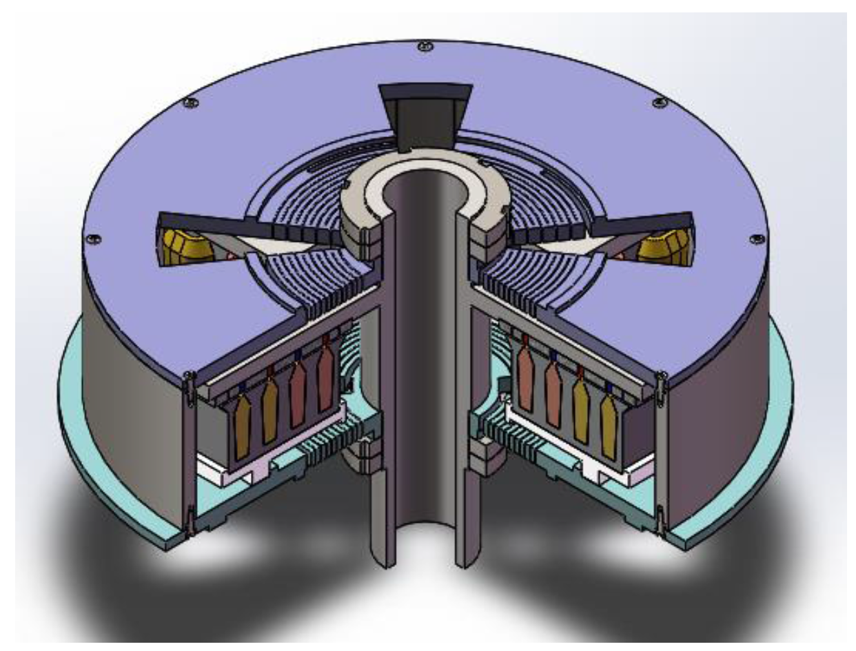
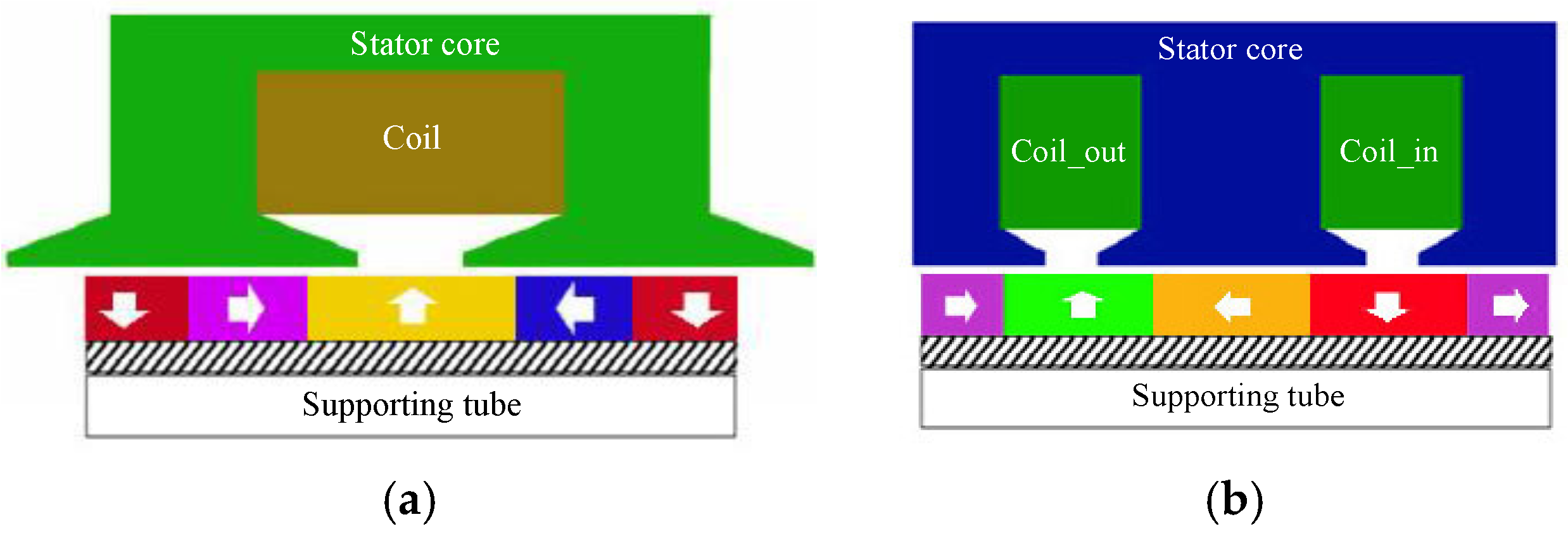
2. Design Principle and Topology of PM LOA

Single-phase short-stroke PM LOA can be divided into two configurations [9]: C-core with one slot and E-core with two slots, as shown in Figure 2. For linear planar motion, the actuator can be cut along axial direction at any location. There are two ways to close the open coil: either only one coil winds around the stator yoke, or two coils wind around the stator teeth. The coil of C-core no longer has superiority than the coil of E-core because the winding factor will not be 1, so this paper adopts E-core quasi-Halbach magnetized topology and coil configuration.

3. Influence of Stator Configuration on Thrust Force

3.1. Goal and Method of Comparative Design

The preliminary design goals of the proposed actuator are to maximize its thrust force density and to minimize the ripple of thrust force. Copper loss and core loss decreased correspondingly and the efficiency improved.
The thrust force per area fρ, and the thrust force ripple fσ, which greatly influence the operating capability of the LOA [10,11], are defined as
f σ = F max F min F max + F min × 100 % ,
Here, Favg is the average thrust force over the stroke, τp is the width of the unit actuator, be is the added width of each side of the stator teeth, and Lfe is the length of stator core. Fmax is the maximum force over the stroke, and Fmin is the minimum thrust over the stroke.
The aim of the comparative design is to find a good balance between the maximum of the thrust force density and the minimum of the thrust force ripple, and is also to control the core loss.
According to the theory of electrical machine design, the air-gap shear stress is
σ A × B ,
Here, A is the electrical loading of a machine, and B is the magnetic loading. The permanent magnet can be designed to improve the magnetic loading [8]. Increasing the electrical loading A can improve the force density of a machine. At the same time, in order to restrict the temperature rise, the force density of a machine is affected by the heat loading q
q A × J ,
Here, J is current density of coil. In air-cooled machines, the product AJ ranges from 100 A2/mm3 to 400 A2/mm3, in the case of direct water cooling, AJ can reach 2000 A2/mm3.
Because electrical loading A appears in shear stress and heat loading at the same time, choosing a small current density and a large electrical loading can improve the thrust force density of LOA. The current density was kept at J = 4.5 A/mm2 and electrical loading at A = 90 A/mm, so the product AJ was 405 A2/mm3, which is a common value in electrical machines, and the LOA can operate in air-cooled mode.
The cross-section of the designed LOA is shown in Figure 3, and the design parameters are listed in Table 1.
The total current is distributed in the slot of LOA, and the needed slot area is as follows
S = A × τ p J × k f ,
Here, kf is the slot-fill factor and was kept to be 0.67, so the slot area was 960 mm2. As shown in Figure 3, the slot area was defined as
S = 1 2 [ ( b 0 + b 1 ) h 1 + ( b 1 + b 2 ) h 2 ] ,
The area of the slot was kept constant, and the design parameters of the stator core were kept within a reasonable range to produce an optimal combination of parameters that could maximize the thrust force density and keep the thrust force ripple at a low level, the copper loss will keep low at the same time. Slot height hs is firstly considered during the optimization since hs has the most considerable influence on thrust force. b0 is then considered in the process to avoid tooth tips to be saturated.
The influence of stator iron loss on the operational efficiency should not be neglected and the magnetic field distribution in the stator tooth can directly indicate iron loss, so the variations of the flux densities in stator teeth are investigated in [8]. In this way, the average flux density of tooth can be controlled under 1.5 T to avoid the stator teeth saturation, thereby, the stator core loss can be efficiently controlled.

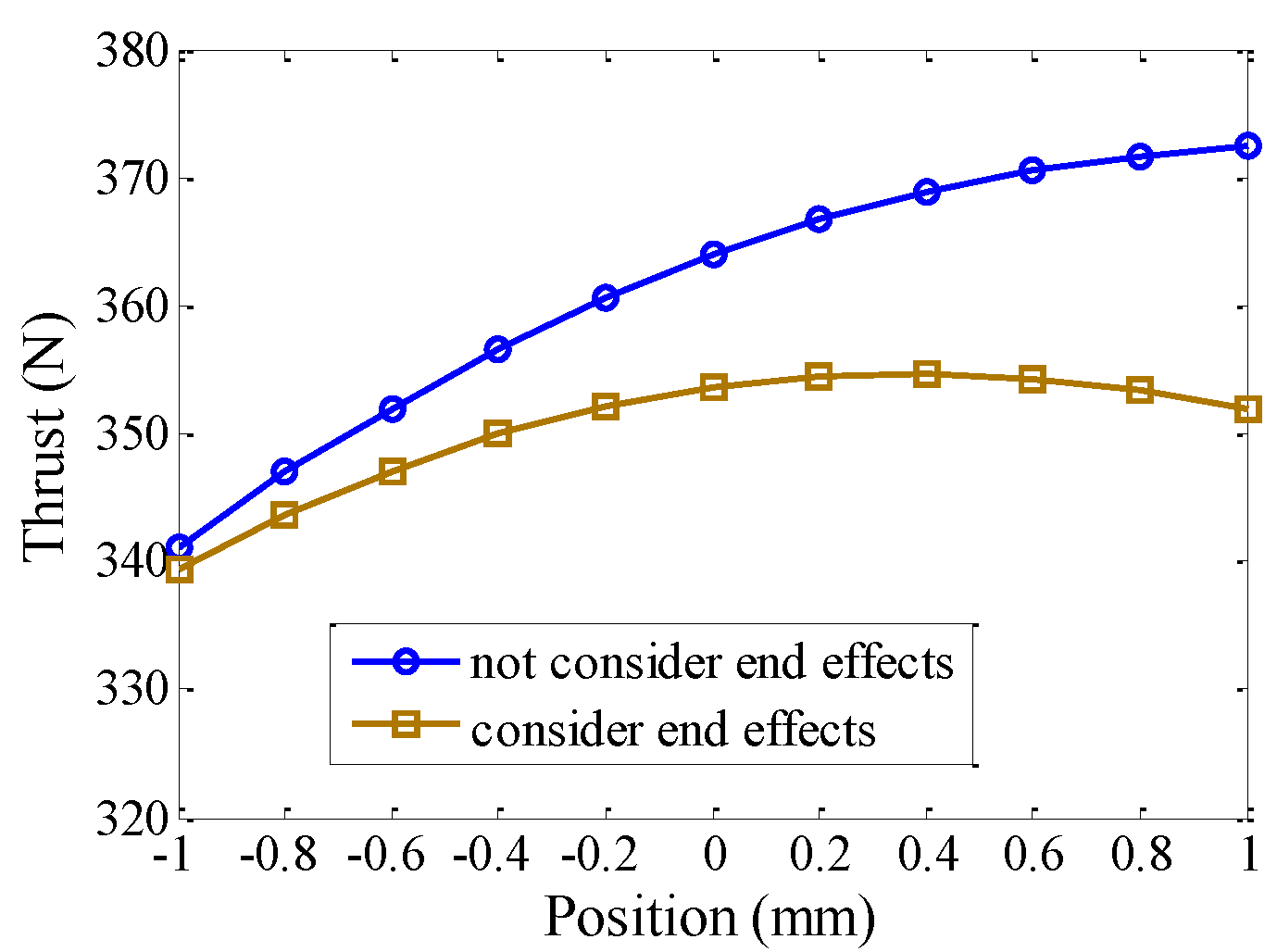
3.2. Influence of End Effects

Actuators with E-shaped cores consist of two unit C-shaped cores and the optimal width is 2τp = 64 mm [8]. End effects were not considered here during the design of the unit configuration. Therefore, a reduction would be brought to the thrust force to some extent if end effects are considered.
The configuration shown in Figure 3 was adopted to compensate for the reduction in thrust force caused by the end effects and to reduce the ripple of thrust force: two radially magnetized magnets are mounted on both sides of the mover and the E-shaped core has tooth tips on either side. The arrows represent the orientations of magnetization.
Figure 4 shows the thrust forces produced by the PM LOA over the stroke range with an ideal C-core and with the E-core. As shown, the average thrust forces were 350 N and 361 N with and without end effects, respectively. The thrust force of ideal C-core LOA without end effects was greater than the E-core LOA with end effects, but the thrust force ripple was also greater.

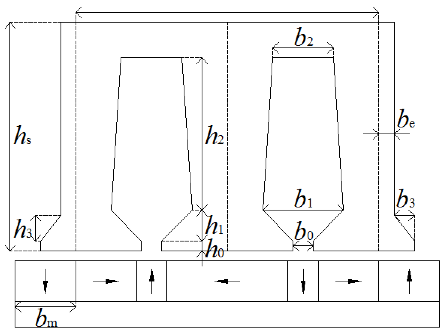
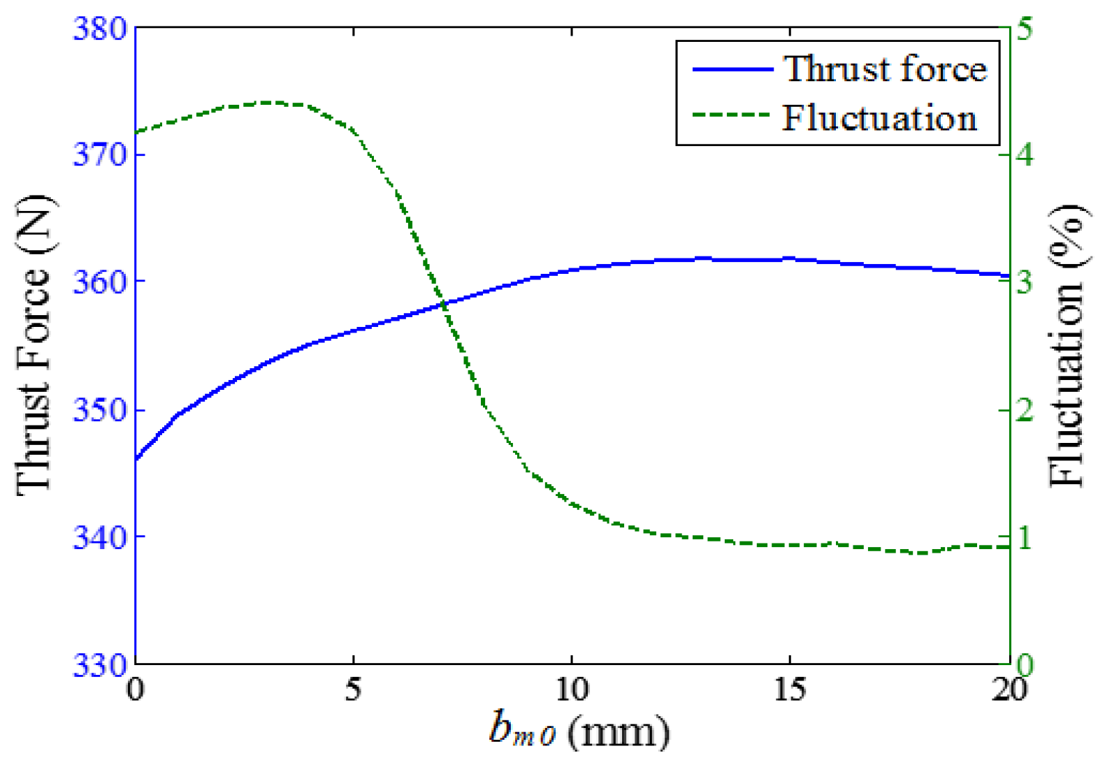
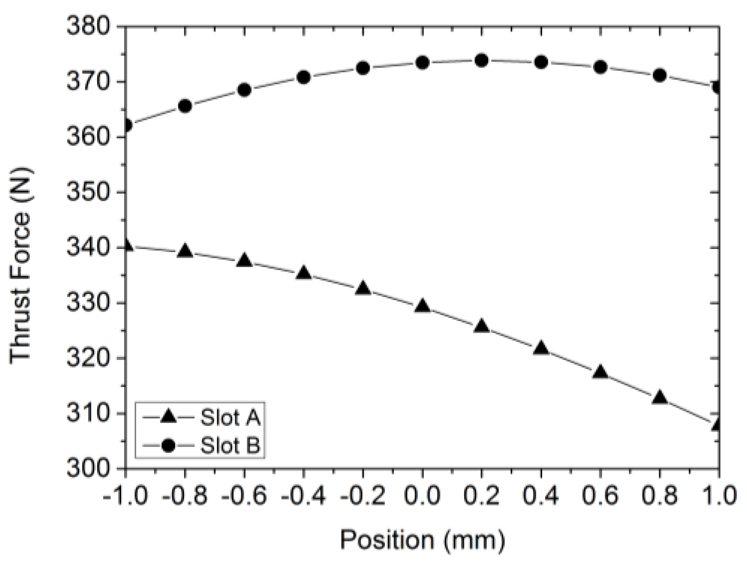
3.3. Influence of Design Parameters on Thrust Force

The design parameters of stator core—such as stator height, slot height, and slot width—were parameterized, but the slot area was kept constant. The thrust force was computed using FEA. The relationship between design parameter and thrust force was determined. The influence of stator teeth tip and lateral magnet on thrust force was analyzed.
Figure 5 shows the variations in thrust force and its fluctuation with stator height hs. As shown, hs has considerable influence on the thrust force. The thrust force increases with hs, and as hs exceeds a certain of level, it slows with increasing hs. The fluctuation of thrust force can be minimized at an hs of 72 mm. Because the magnetic circuit was not saturated, the variation of hs affected the flux density of stator yoke region. As hs increased, the flux density of stator yoke decreased. Once the flux density of the stator yoke reached a certain level and ceased to vary, the consumption of the stator core increased with hs and the actuator size would be great, which rendered it capable of reducing thrust force density. Finally, the stator height hs was determined to be 72 mm.
Figure 6 and Figure 7 show the variations in thrust force and their fluctuations with slot height h1 and h2. As shown, the thrust force first increased and then decreased, but the trends in the variation of their fluctuations followed the opposite trend. The optimal thrust force and their fluctuation was observed at an h1 of 13 mm and h2 of 48.55 mm.
Figure 8 shows the variations in thrust force and its fluctuation with slot opening b0. As shown, b0 had a considerable impact. The thrust force first increased and then decreased with the b0. Small b0 values may cause the tooth tips to be saturated and the decrease in magnetic potential to be large, so more flux may not pass through the air gap near the stator core side; large b0 values may cause the thrust force to fluctuate noticeably, so b0 must be set at a reasonable value so that preferable thrust force and its fluctuation can be produced. Optimal thrust force and optimal fluctuation were observed at a b0 of 5 mm. The slot open width b0 was found to be ≈5 mm.
Figure 9 and Figure 10 show the variations of thrust force and its fluctuation with slot width b1 and b2. As shown, the thrust force first increased and then decreased, but the variation in fluctuation showed just the opposite trend. Because b1 was 19 mm and b2 14.1 mm, the optimal thrust force and its fluctuation could be determined.
b1 is not as identical to b2, which was produced by the comparative design given above. For this reason, the shape of the stator tooth is unparalleled. Part of slot leakage flux passes through the slot region to form a loop and chains across some of the coils; another part traverses the slot opening to form a loop and chains across all the coils. In this way, the flux that passes through the top of the tooth region was slightly less pronounced than that of the slot root region. When the paralleled tooth was used, the tooth root region became saturated much more easily than the area surrounding the top of the tooth. The design scheme of unparalleled teeth was used because it may reduce the flux density of the tooth root region and correspondingly decrease the iron loss caused by the stator core, thus increasing actuator efficiency.
Figure 11 shows the variations of thrust force and its fluctuation with lateral tooth tip width b3. As shown, the thrust force had a monotonically decreasing property with b3. The thrust force fluctuation reached a minimum as b3 approached 7 mm. For this reason, b3 was set to 7 mm.
Figure 12 shows the variations in thrust force and its fluctuations with stator lateral width be. As shown, the thrust force displayed no obvious variation as be increased and its fluctuation varied by 4.8%. Fluctuation was minimum at a be of 0 mm. Hence, be has been chosen to be 0 mm, which is equivalent to the structure of two C-cored actuators with τp being 32 mm combined together without additional top width of stator core.
Figure 13 shows the variations in thrust force and its fluctuation with bm0. As shown, bm0 had little impact on the thrust force and prominently influenced its fluctuation. The thrust force increases slowly with gradual increasing bm0 and its fluctuation first increased slowly and then decreased rapidly. The thrust force and its fluctuation ceased to show visible variations as bm0 approached 11 mm. The lateral magnet width bm0 was set to ≈15 mm.

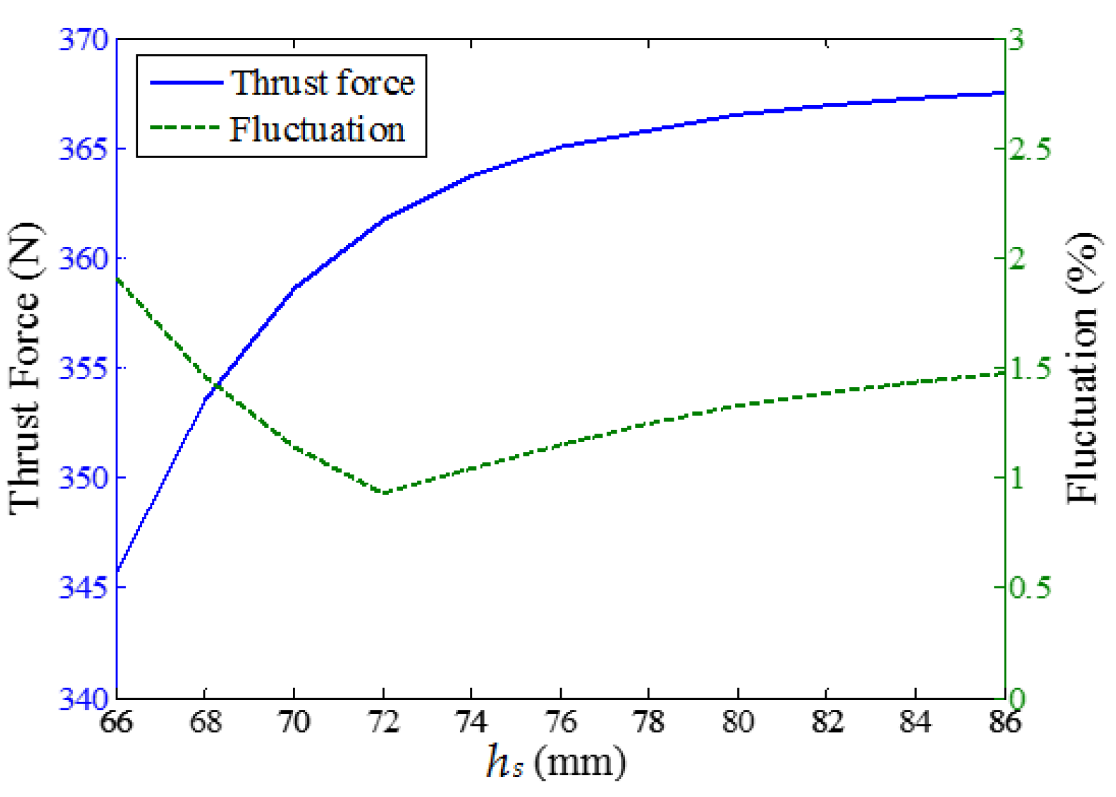
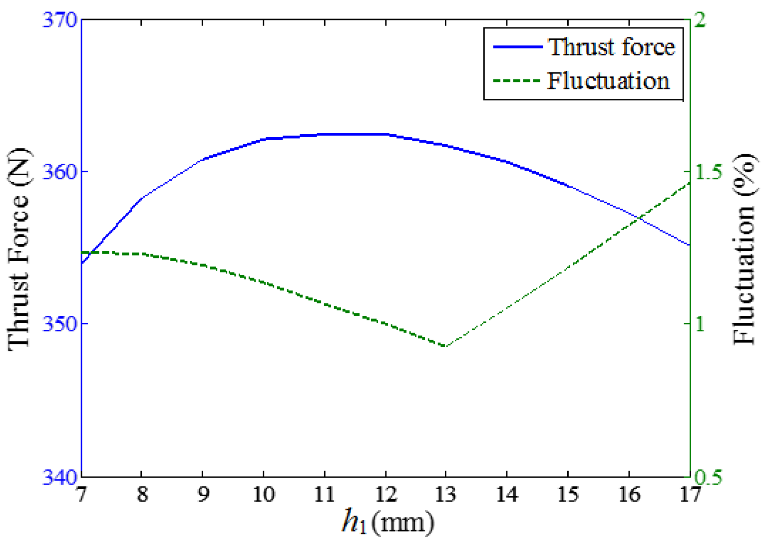
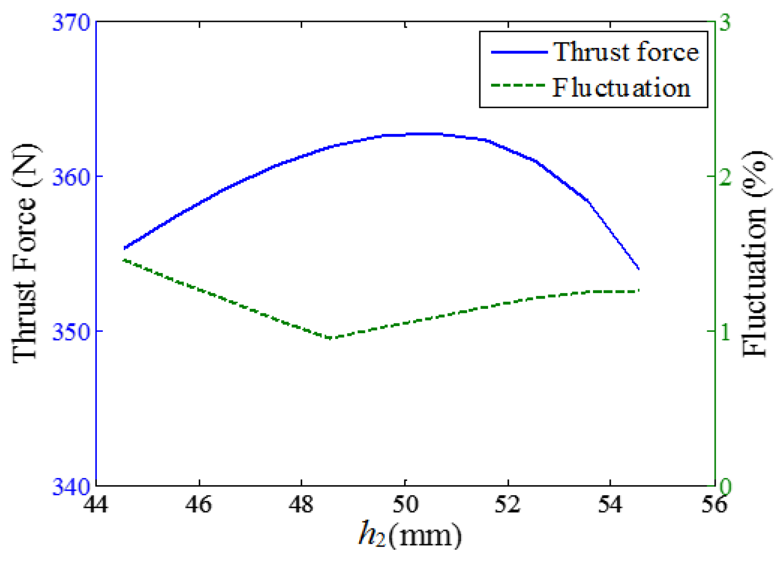
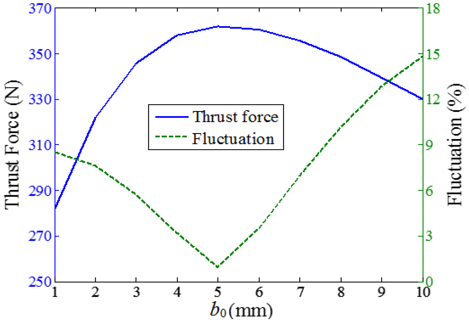
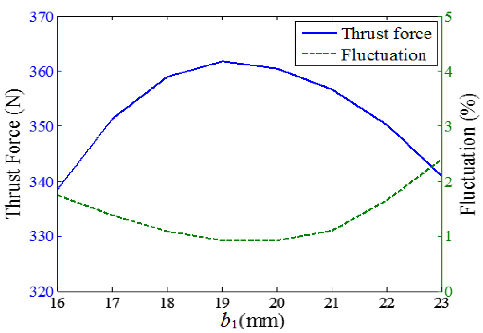
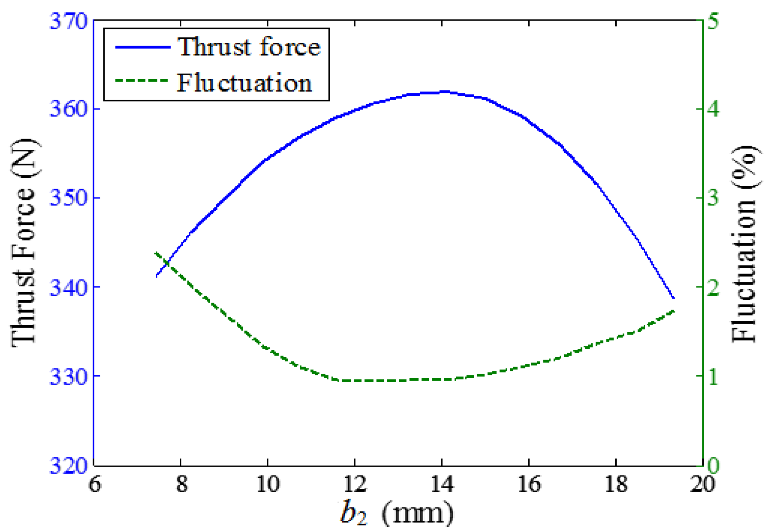
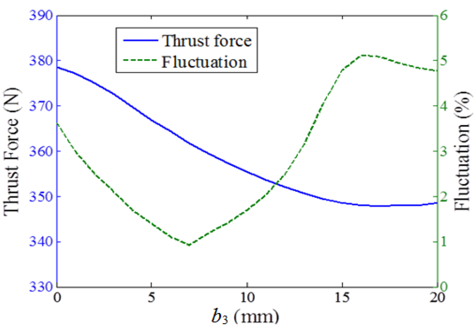
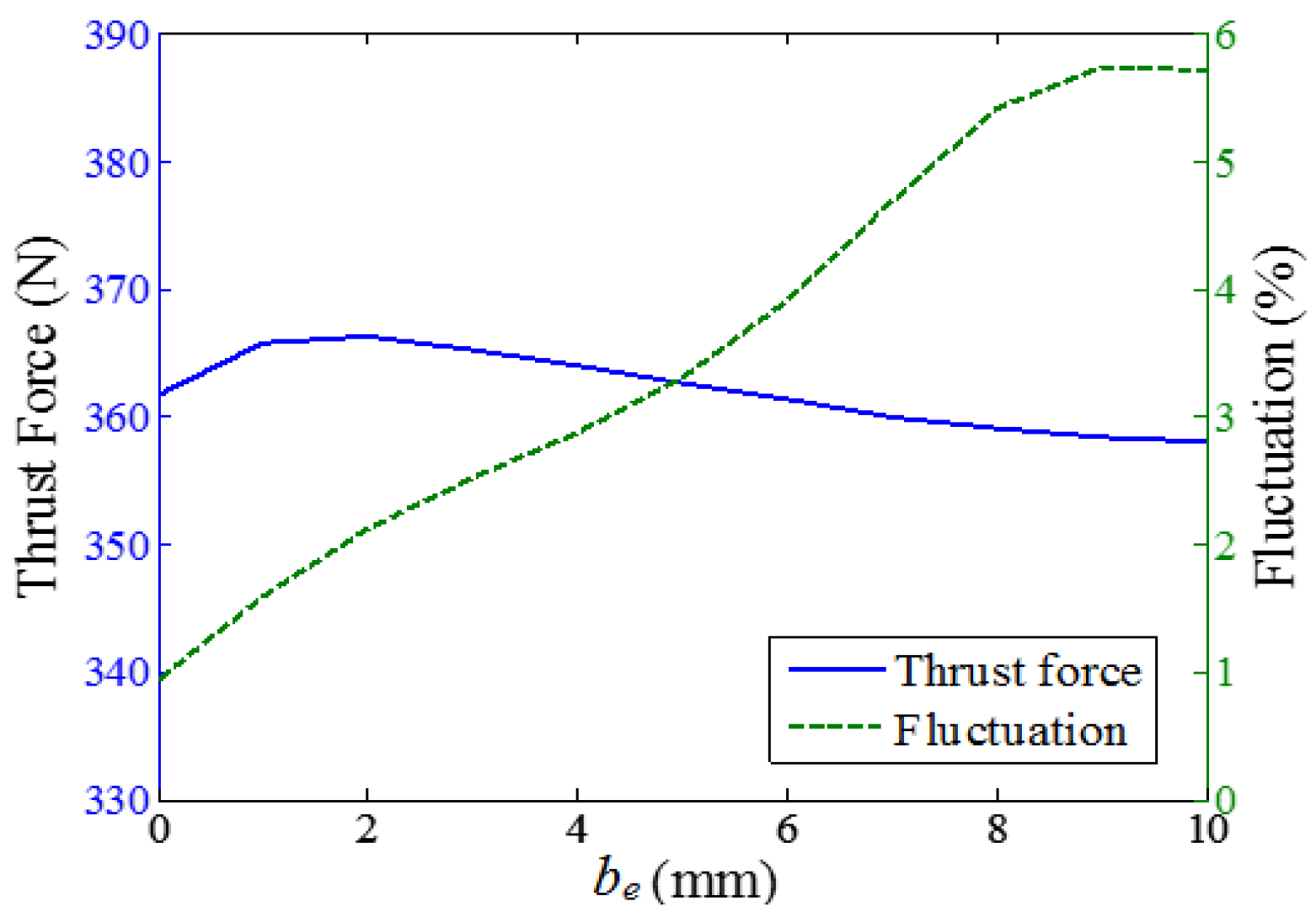
3.4. Influence of Design Parameters on Thrust Force

The optimal combination of design parameters was found, and the final slot (slot A) size is given in Table 2. Another commonly used slot (slot B) with the paralleled tooth is also given for comparison.
The thrust forces also changed with stroke range. As the position varied between −1.0 mm and 1.0 mm. The average thrust force of LOA with slot A and slot B was 370.3 N and 327.2 N, respectively, and the thrust force ripple was 1.6% and 5%, respectively as shown in Figure 14. The average thrust force of LOA with slot A was increased 13.2% more than in slot B, and the thrust force ripple was 68% lower. The thrust force density of LOA with slot A increased to 115,700 N/m2.

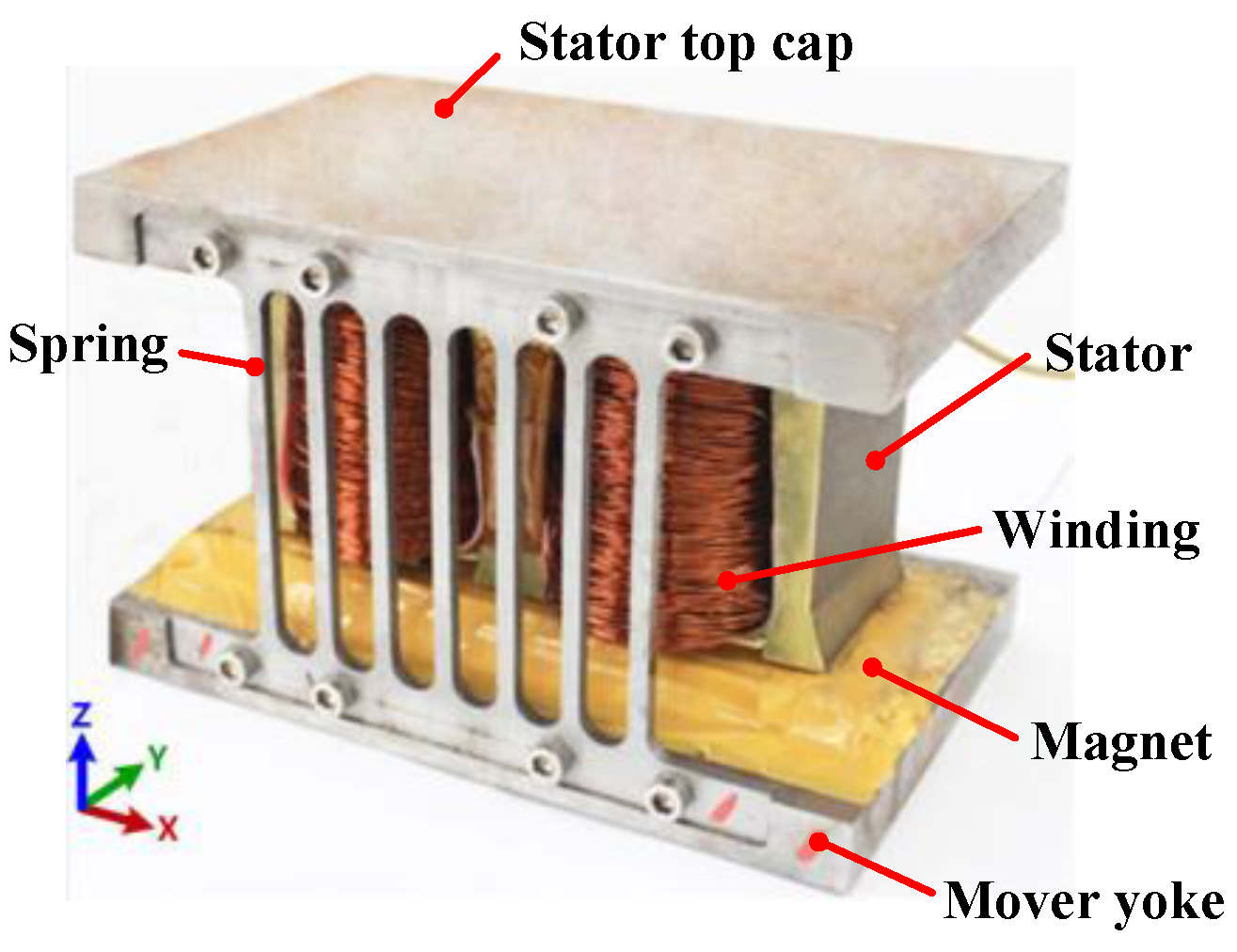
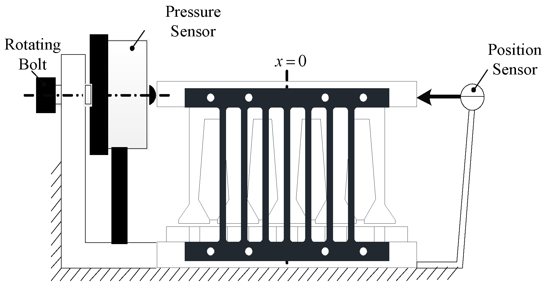
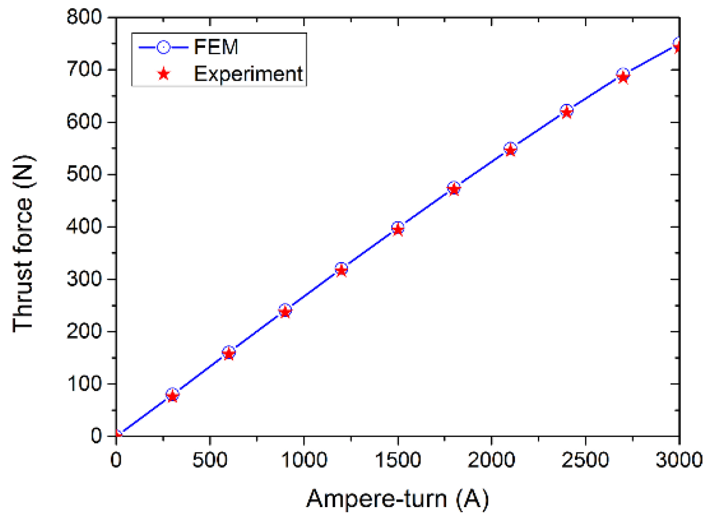
4. Prototyping and Experiments

A prototype has been manufactured to allow experimental validation of the analyses given above (Figure 15). The prototype is composed of various components including a stator top cap, a stator, a spring, the windings to produce an alternating magnetic field, the mover yoke, and a magnet to produce a constant magnetic field. The stator of a single-phase PM prototype is attached to a rectangular tank in a stainless steel lid. The spring that connects the stator and the mover is embedded between the lid and motor yoke. It has the function of strutting to guarantee that the air-gap length is 2 mm. In addition, the spring should have enough stiffness to ensure that when current of stator windings is zero, the stator does leave its initial position (x = 0, y = 0). When the mover is fixed, the stator can repeat a reciprocating motion under the action of the electromagnetic force. The schematic diagram of experimental device is shown in Figure 16.
The initial position of the stator is measured using a position sensor under the condition that the current of stator windings is zero. When a DC voltage is applied to the windings, the stator is forced to move leftward by the electromagnetic force accordingly. Meanwhile, the stator windings are also subjected to a rightward spring force. The spring force will decline if the stator is subjected to another rightward force generated by a rotating bolt and it will decrease to zero when the stator returns to its initial position. Then the output voltage can be measured by the pressure sensor while the current can be recorded according to the DC power supply. Thus, the electromagnetic force to which stator windings are subjected at the initial position can be calculated by converting the output voltage into the corresponding force. By changing the applied DC voltage and repeating the aforementioned steps, a figure can be drawn that depicts the changes in electromagnetic force with current.
The predicted thrust force–current characteristics (Figure 17) are compared and measured. As shown, there was strong agreement between the FE predicted, and results were measured. When the figure of ampere-turn was between 0 and 2500 A, there was a linear relationship between the thrust force and the ampere-turn. However, when the figure of ampere-turn was over 2500 A, the two factors showed a nonlinear relationship because of the magnetic saturation in the actuator. The increase in the temperature of the prototype winding was only 43 °C, which indicated that the quasi-Halbach magnetized LOA had superior overload performance.

5. Conclusions

To achieve the desirable performance of OFVA, an E-cored quasi-Halbach magnetized LOA has been comparatively designed and its electromagnetic performances were analyzed by FEA. The optimal design parameters have been presented, the thrust force density was increased, and the thrust force ripple was reduced. Predicted and measured results showed strong agreement.
Comparative design of the stator can improve thrust force density and reduce thrust force ripple of LOA. Reducing the current density while increasing electrical loading can increase the thrust force density. Using a stator with unparalleled teeth and increased slot height can increase the thrust force density. The slot’s open width was found to have a significant effect on the thrust force density and thrust force ripple.

Acknowledgments

This work is supported by National Key Basic Research Program of China under Grant 2013CB035600.

Author Contributions

J.H. and M.Z. conceived and designed the experiments; J.H. and Y.L. performed the experiments; J.H. and J.Z. wrote the paper.

Conflicts of Interest

The authors declare no conflict of interest.

References

  1. Chen, L.; Li, W.Y.; Ma, T.J. The state of the art and perspectives of linear friction welding technology. Adv. Aeronaut. Sci. Eng. 2010, 1, 178–183. [Google Scholar]
  2. Lee, H.K.; Song, G.Y.; Park, J.S.; Hong, E.P.; Jung, W.H.; Park, K.B. Development of a linear motor for compressors of household refrigerators. In Proceedings of the International Compressor Engineering Conference, West Lafayette, IN, USA, 25–28 July 2000; pp. 283–286. [Google Scholar]
  3. Goto, A.; Okamoto, T.; Ikariga, A.; Todaka, T.; Enokizono, M. A New Moving-magnet Type Linear Actuator utilizing Flux Concentration Permanent Magnet Arrangement. J. Electr. Eng. Technol. 2012, 3, 342–348. [Google Scholar] [CrossRef]
  4. Hong, S.K.; Ro, J.S.; Jung, H.K. Optimal Design of a Novel Permanent Magnetic Actuator using Evolutionary Strategy Algorithm and Kriging Meta-model. J. Electr. Eng. Technol. 2014, 9, 471–477. [Google Scholar] [CrossRef]
  5. Lu, Q.F.; Yu, M.H.; Ye, Y.Y.; Fang, Y.T.; Zhu, J.G. Thrust Force of Novel PM Transverse Flux Linear Oscillating Actuators With Moving Magnet. IEEE Trans. Magn. 2011, 47, 4211–4214. [Google Scholar] [CrossRef]
  6. Fujimoto, Y.; Kominami, T.; Hamada, H. Development and Analysis of a High Thrust Force Direct-Drive Linear Actuator. IEEE Trans. Ind. Electr. 2009, 56, 1383–1392. [Google Scholar] [CrossRef]
  7. Wang, J.B.; Atallah, K.; Wang, W.Y. Analysis of a Magnetic Screw for High Force Density Linear Electromagnetic Actuators. IEEE Trans. Magn. 2011, 47, 4477–4480. [Google Scholar] [CrossRef]
  8. Xu, F.; Hu, J.H.; Zou, J.B.; Li, Y.; Xu, Y.X.; Fan, H. Comparative investigation of permanent magnet linear oscillatory actuators used in orbital friction vibration machine. Int. Symp. Appl. Electromagn. Mech. 2014, 45, 581–588. [Google Scholar]
  9. Wang, J.; Howe, D. A tubular permanent magnet machine equipped with homopolar windings. In Proceedings of the International Symposium on Linear Drives for Industry Applications (LDIA 2005), Kobe-Awaji, Japan, 25–28 September 2005; pp. 239–242. [Google Scholar]
  10. Yeo, H.K.; Woo, D.K.; Lim, D.K.; Ro, J.S. Analysis of a Surface-Mounted Permanent-Magnet Machine with Overhang Structure by Using a Novel Equivalent Magnetic Circuit Model. J. Electr. Eng. Technol. 2014, 9, 1960–1966. [Google Scholar] [CrossRef]
  11. Ahn, H.M.; Oh, Y.H.; Song, K.D.; Kim, Y.I.; Kho, H.R.; Choi, M.S.; Hahn, S.C. Optimal Design of Permanent Magnetic Actuator for Permanent Magnet Reduction and Dynamic Characteristic Improvement using Response Surface Methodology. J. Electr. Eng. Technol. 2015, 10, 935–943. [Google Scholar] [CrossRef]
Figure 1. Proposed a permanent magnet (PM) orbital friction vibration actuators (OFVA).
Applsci 07 00630 g001
Figure 2. Topology of short stroke single-phase quasi-Halbach PM linear oscillating actuators (LOA). (a) C-core with one slot in stator; (b) E-core with two slots in stator.
Applsci 07 00630 g002
Figure 3. Cross-section of the E-cored LOA.
Applsci 07 00630 g003
Figure 4. Thrust forces of initial LOA over the stroke range.
Applsci 07 00630 g004
Figure 5. Variations of thrust force and its fluctuation with hs.
Applsci 07 00630 g005
Figure 6. Variations in thrust force and its fluctuation with h1.
Applsci 07 00630 g006
Figure 7. Variations in thrust force and its fluctuation with h2.
Applsci 07 00630 g007
Figure 8. Variations of thrust force and its fluctuation with b0.
Applsci 07 00630 g008
Figure 9. Variations in thrust force and its fluctuation with b1.
Applsci 07 00630 g009
Figure 10. Variations in thrust force and its fluctuation with b2.
Applsci 07 00630 g010
Figure 11. Variations in thrust force and its fluctuation with b3.
Applsci 07 00630 g011
Figure 12. Variations in thrust force and its fluctuation with be.
Applsci 07 00630 g012
Figure 13. Variations in thrust force and its fluctuation with bm0.
Applsci 07 00630 g013
Figure 14. Variations in thrust forces with position.
Applsci 07 00630 g014
Figure 15. Prototype LOA.
Applsci 07 00630 g015
Figure 16. Schematic diagram of experimental device.
Applsci 07 00630 g016
Figure 17. Variations in thrust forces with ampere-turns.
Applsci 07 00630 g017
Table 1. Design parameters of the E-cored LOA
Design ParameterValue
Stator core width 2τp (mm)64
Stator core length Lfe (mm)50
Air-gap length g (mm)2
Magnet thickness hm (mm)10
Magnet (N38SH) remanence Br (T)1.23
Table 2. Design parameters of the E-core stator
ItemsValue
Slot ASlot B
Slot open width b0 (mm)53
Slot top width b1 (mm)1919.5
Slot bottom width b2 (mm)14.119.5
Lateral tooth tip width b3 (mm)77
Lateral tooth width be (mm)00
Lateral magnet width bm0 (mm)1515
Tooth tip height h0 (mm)22
Tooth top height h1 (mm)136
Tooth bottom height h2 (mm)48.5545.76
Lateral shoulder height h3 (mm)99
Stator height hs (mm)7261.9

